Article

Effects of PWHT on the Residual Stress and Microstructure of Bisalloy 80 Steel Welds

1
School of Mechanical Engineering, The University of Adelaide, Adelaide, SA 5005, Australia
2
Australian Nuclear Science and Technology Organisation (ANSTO), Lucas Heights, NSW 2234, Australia
3
School of Civil Engineering, The University of Sydney, Sydney, NSW 2006, Australia
*
Author to whom correspondence should be addressed.
Metals 2022, 12(10), 1569; https://doi.org/10.3390/met12101569
Submission received: 28 July 2022 / Revised: 2 September 2022 / Accepted: 14 September 2022 / Published: 21 September 2022
(This article belongs to the Special Issue Welding and Joining of Advanced High-Strength Steels)

Abstract

:
Quenched and tempered (Q & T) steels have numerous applications, particularly in the defence industry with welding as the main fabrication route. Since welding imparts stresses due to thermal gradients development during welding, plus the fact that the Q & T fabricated structures are expected to function in a complex loading environment, it is critically important to relax the welding stresses before exposing the parts to service conditions. The present study reports on the generated residual stresses when Bisalloy 80 is welded by pulsed gas metal arc welding (GMAW-P) and verifies the effects of post-weld heat treatment (PWHT) on the microstructural changes, removal or reduction of residual stresses and the resulting mechanical properties of the welded Q & T steel joints. Neutron diffraction was utilized to measure the residual stresses in the as-welded and after PWHT of the Bisalloy 80 steel weldments. High levels of tensile residual stresses reaching to the yield strength of the weld metal were present (642 ± 24 MPa) in the as-welded joints but were substantially reduced after PWHT (145 MPa ± 21 MPa, which is ~23% of the yield strength of the weld metal). PWHT led to microstructural changes in different regions of the parent and weld metals, including the formation of coarsened polygonal ferrite grains and bainitic ferrite laths. This finding is in line with hardness measurements, where hardness reductions were evident in the heat-affected zone (HAZ) and the weld metal (WM) of the heat-treated specimens.

1. Introduction

Quenched and tempered (Q & T) steels are widely used for a diverse range of applications, from armoured vehicles in defence forces [1,2] to structural and wear-resistant applications such as mining [3]. Q & T steels have the unique characteristics of superior toughness, improved strength to weight ratio and high hardness coupled with relatively good weldability. These qualities make them the candidate material for non-conventional applications where the loading conditions are complex and enforced at great speed, i.e., shock loading, as experienced when ballistic projectiles and/or explosions are encountered [4,5,6]. The superior weldability of these alloys, although effective in mitigating the formation of weld cracks, still undergo microstructural changes during welding, which may compromise the integrity of welded joints [6,7]. One of the outcomes of microstructural changes is the softening of the heat affected zone (HAZ) with detrimental effects on the performance of the welded structure due to a reduction in the creep and fatigue properties of the welded joints, thus compromising the integrity of the welded structure [8,9,10,11]. This is due to the large heat input from the arc during the GMAW process, where the softened heat-affected zone reduces the ductility and strength of welds and makes the weld weaker than the base metal [12]. Although the coarsening of grains in HAZ was confirmed by Gorka and Kotarska [13] during welding of fine grained Q & T steel, they indicated that the grain growth does not affect the strength of the welded joint.
Additionally, the microstructure of Q & T steel welds, including the HAZ, plays a major role in weld joint susceptibility to hydrogen cracking, especially hydrogen-assisted cold cracking (HACC). This is due to variations in the hydrogen solubility of the weld metal and base plate during cooling as the determining factor to the crack susceptibility of the weld joint and its surroundings [14]. Furthermore, HACC formation is also dependent on the stresses experienced by the welded structures, both in service (external applied loads) and residual stresses generated during fabrication [15,16]. The development of residual stresses in the weld region as well as the adjacent areas is inevitable due to phase changes and differential cooling/heating rates experienced by the structure during fabrication [17,18,19].
Therefore, understanding and subsequent relaxation of the residual stresses in the welded joints of Q & T steels is of fundamental importance, as they are frequently exposed to significant and complex loading conditions. For instance, tensile residual stresses could jeopardize the structural integrity of Q & T steels in the presence of external fatigue or creep loading conditions, as is commonly seen in military/armour applications [20,21].
Fortunately, residual stresses can be alleviated through PWHT. PWHT is applied to improve the mechanical properties of the welded structure by tempering the martensitic structure, restoring deformability and improving the load-carrying capability of the structure in service [22,23]. However, PWHT can introduce unexpected microstructural changes in the HAZ and WM, and thus great care needs to be taken when designing the heat treatment procedures for high strength Q & T steel welds [24,25].
PWHT for Q & T steel welded joints is typically carried out at temperatures between 540 and 590 °C for a holding time dependent on the plate thickness [26]. However, the effectiveness of PWHT on the reduction of residual stresses in Q & T joints needs to be evaluated, as insufficient relaxation of the stresses could have adverse impacts on the integrity of the joints under applied/operating loads and may contribute to HACC initiation. In addition to understanding residual stress changes after PWHT, characterization of changes in the microstructure and mechanical properties also need to be addressed. A study conducted by Sterjovski et al. [26] on the PWHT effects on Bis80 weldments, a Q & T steel, showed a reduction in tensile and yield strength of the samples after PWHT. The finding is consistent with the hardness results, where significant softening of HAZ and weld metal (WM) occurred after PWHT. The same study showed, via hole drilling residual stress measurements, that PWHT is effective in substantially reducing the surface residual stress in the Q & T joints. Sterjovski et al. [27] also studied the effects of PWHT on the toughness and fatigue crack growth of the Q & T pressure vessel steels (two different plate thicknesses of 11 mm and 12 mm). The crack tip opening displacement (CTOD) fracture toughness for both plate thicknesses was decreased with increases in the number of PWHT cycles. A decrease in the impact toughness of the parent metal (PM) was also observed with an increase in the number of PWHT cycles or holding time with a progressive change in the fracture mode towards a more brittle fracture, mainly due to precipitation of brittle phases, such as carbides. Despite significant microstructural analysis and mechanical properties characterization of heat-treated welded Q & T steel structures, there is a lack of quantitative information on the residual stresses in the welded joints pre and post PWHT. Therefore, this study utilized neutron diffraction to characterize residual stresses in conjunction with microstructure and mechanical properties, pre and post PWHT, in a multi-pass Bisalloy 80 steel weldment fabricated by GMAW-P.

2. Materials and Methods

2.1. Base and Filler Material
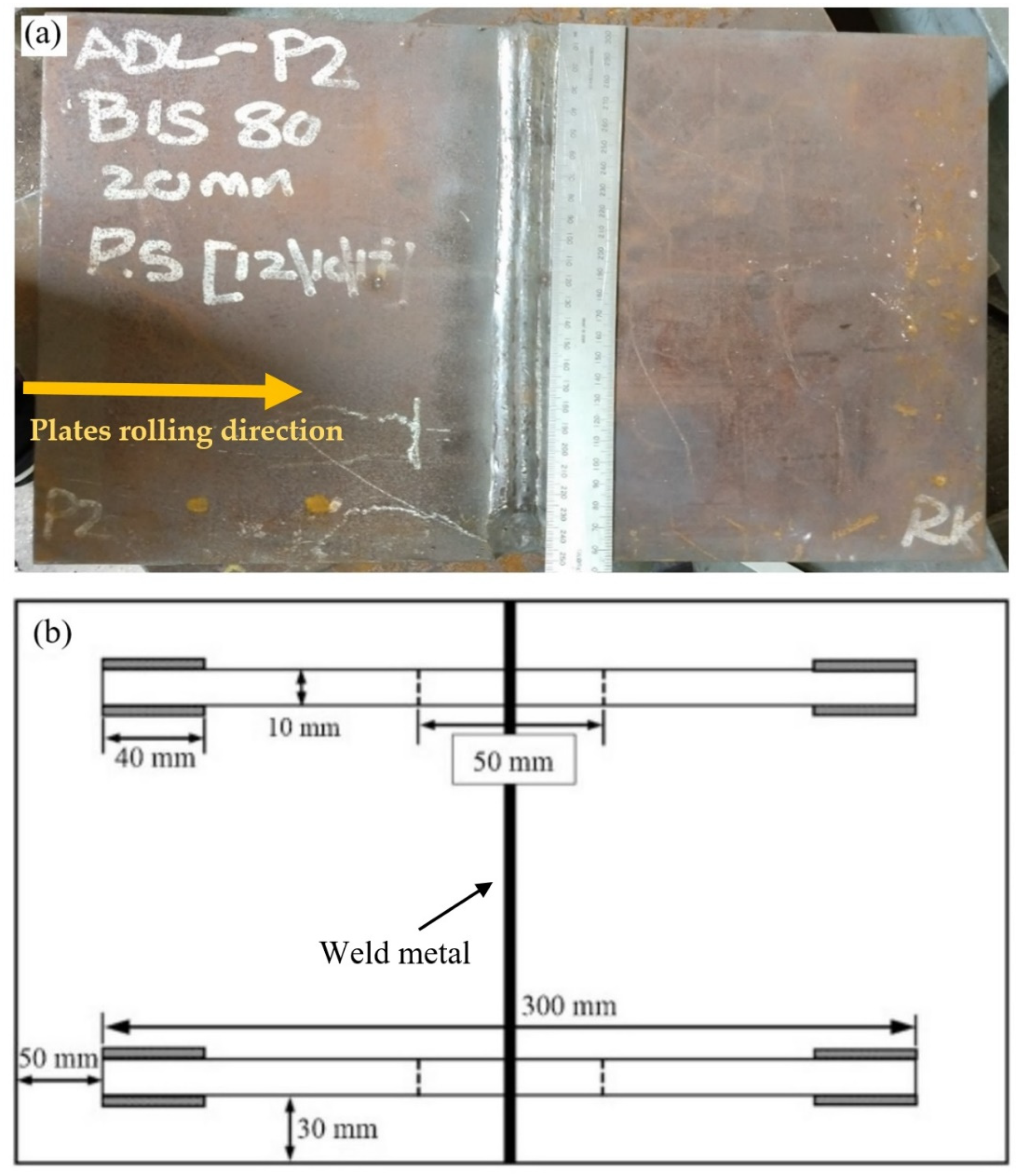
A Bisalloy 80 (AS 3597-2008 GRADE 700, Bisalloy Steel Group Limited, Wollongong, Australia) steel plate of 20 mm thickness was sectioned into 250 mm × 200 mm plates and joined together with 16 weld passes. The plates were clamped during welding, and the clamps were removed after completion of the welds. The optical photograph and schematic diagram in Figure 1 show the welded sample geometry and the clamp positions, respectively. The chemical composition of the base material and the consumable wire (1.2 mm diameter), as provided by the manufacturer, are given in Table 1.

2.2. Welding

Gas metal arc welding-pulse (GMAW-P) was utilized to join two V-prep plates with the dimensions of 250 mm × 200 mm × 20 mm in accordance with AS/NZS 3992-2015 [28]. The consumable wire (A5.28) with 1.2 mm diameter was used in 16 passes to weld the plates. The pre-heat temperature and maximum inter-pass temperature used during welding were 25 °C and 125 °C, respectively. The welding parameters are summarized in Table 2.

2.3. PWHT

PWHT of the samples was carried out utilizing ceramic heating blankets (i.e., block-shaped sintered alumina heating blankets), similar to our previous investigation for multi-pass high strength low alloy X70 steel welds [18,29]. The soaking temperature was 600 °C (validated by thermocouples that were attached in several locations of the welded plate, including the BM, HAZ and WM), and the holding time was one hour. The ramp up rate was 250 °C/h, and samples were cooled in air.

2.4. Hardness and Microstructural Analysis

The welded coupons were sectioned transversely to the welding direction and polished down to 1 μm diamond paste for the hardness test of the PM, WM and HAZ. Hardness testing was carried out in accordance with the Australian standard AS.2205.6.1 [30]. Vickers microhardness measurements were conducted across the weld (3 mm below the plate top surface) at a nominal load of 0.5 kg and load dwell time of 15 s. Optical microscopy was used to examine the microstructure in different regions of the PM, HAZ and WM. The samples were etched in 2% Nital (2% nitric acid in ethanol) for microstructural characterization.

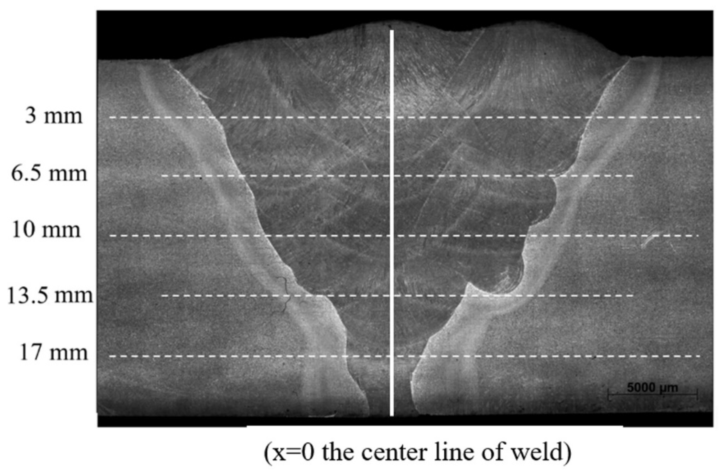
2.5. Neutron Diffraction Stress Measurements before and after PWHT

A Kowari strain diffractometer at ANSTO, located in Sydney (Australia), was utilized to conduct neutron diffraction residual strain/stress measurements. Measurement of residual stresses by neutron diffraction is based on Bragg’s law:
n λ = 2 d sin θ
where θ is the incident or reflection angle, also known as the Bragg angle (scattering angle, 2 θ , is the angle the neutrons are diffracted), λ is the wavelength of the incident neutron beam, d is the spacing between two adjacent crystallographic planes within the crystal structure of the tested material and n is an integer number representing the order of the reflection plane (hkl).
By measuring the stressed (dhkl) and stress-free (dhkl,0) inter-planer spacing, the lattice strain (ε) is calculated, as given in Equation (2).
ε h k l = d h k l d h k l , 0 d h k l , 0
A monochromatic neutron beam with a wavelength of 1.67 and gauge volume of 3   mm × 3   mm × 3   mm was used in the current study to measure the scattering angle from the α-Fe (211) reflection. Residual stress measurements were conducted in three principal directions across the weld for five different lines (3 mm, 6.5 mm, 10 mm, 13.5 mm and 17 mm from the plate top surface), as specified on the transverse section of the weld joint shown in Figure 2. Stress-free samples (a stress-free sample is a cut-out of the plate with the welding parameters identical to the as-received plate, which acts as the baseline for residual stress calculations) were also prepared for both as-welded and heat-treated specimens using electrical discharge machining (EDM). The EDM with a wire diameter of 0.2 mm was utilized for the preparation of the stress-free samples with the dimensions of 6   mm × 80   mm × 20   mm from across the weld and at the centre of the plate. Cutting of stress-free or matchstick samples from the aforementioned area enables full relaxation of the residual stresses [31,32]. The measurements of lattice spacing (d0) for the stress-free samples were conducted for both the as-welded and heat-treated specimens using similar measurement points as per corresponding regions for stressed specimens with 3   mm × 3   mm × 3   mm gauge volume. Residual stress measurements were performed in all three principal directions of longitudinal (parallel with the welding direction), transverse (perpendicular to the weld) and normal (through the thickness of the plate) orientations. Further details of experimentation and neutron diffraction fundamentals is available in the literature [17,18,33].

3. Results and Discussion

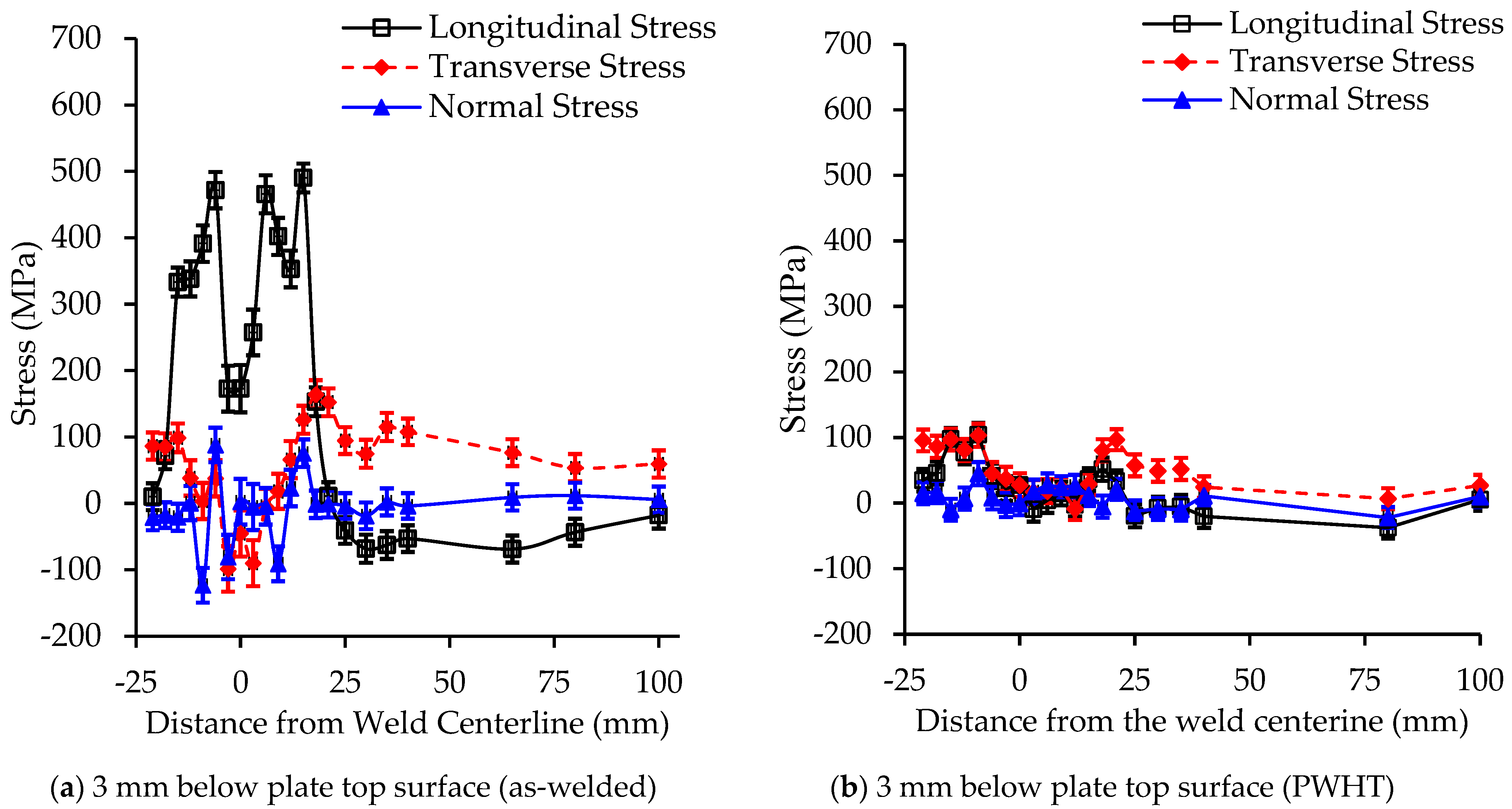
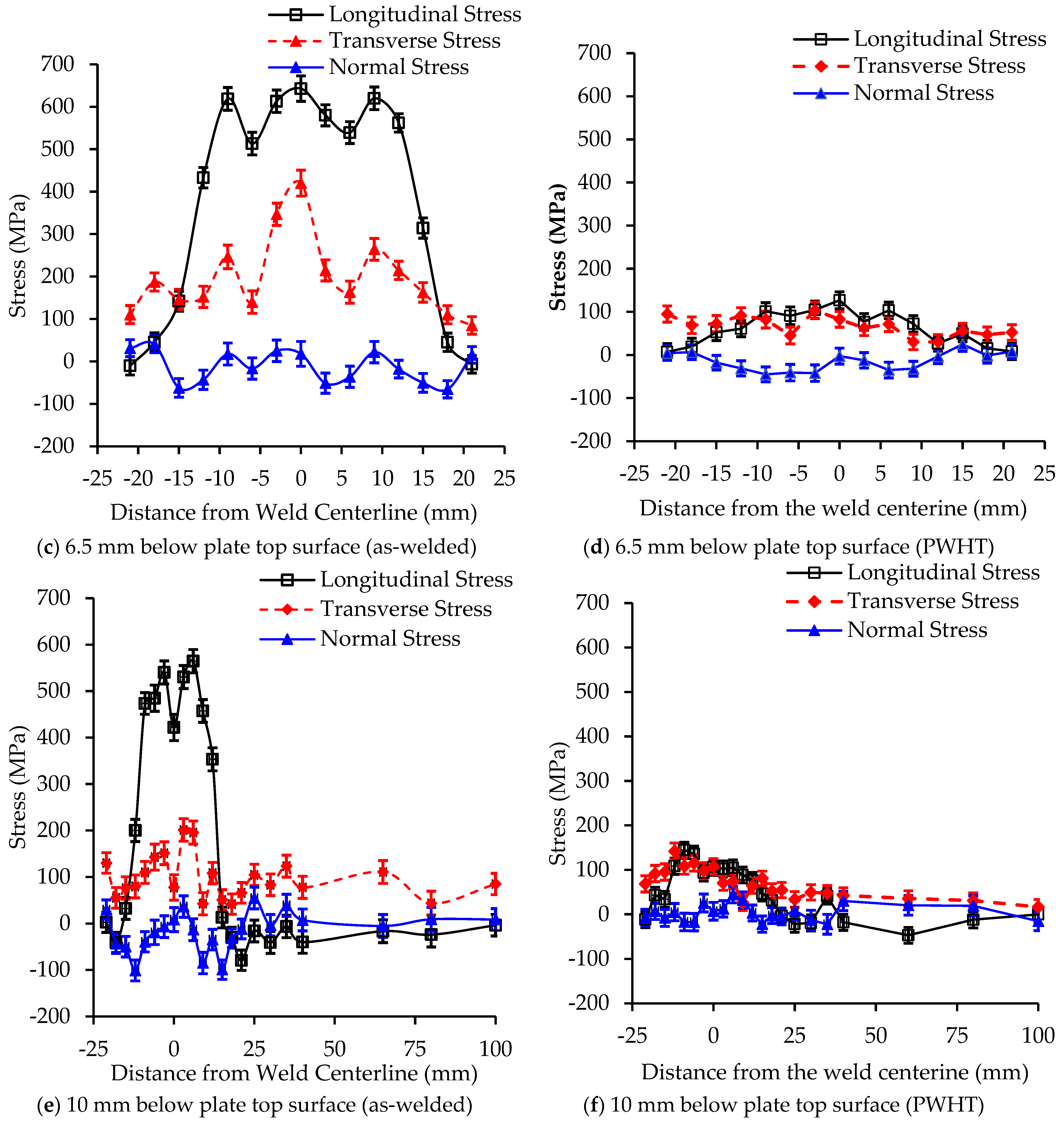
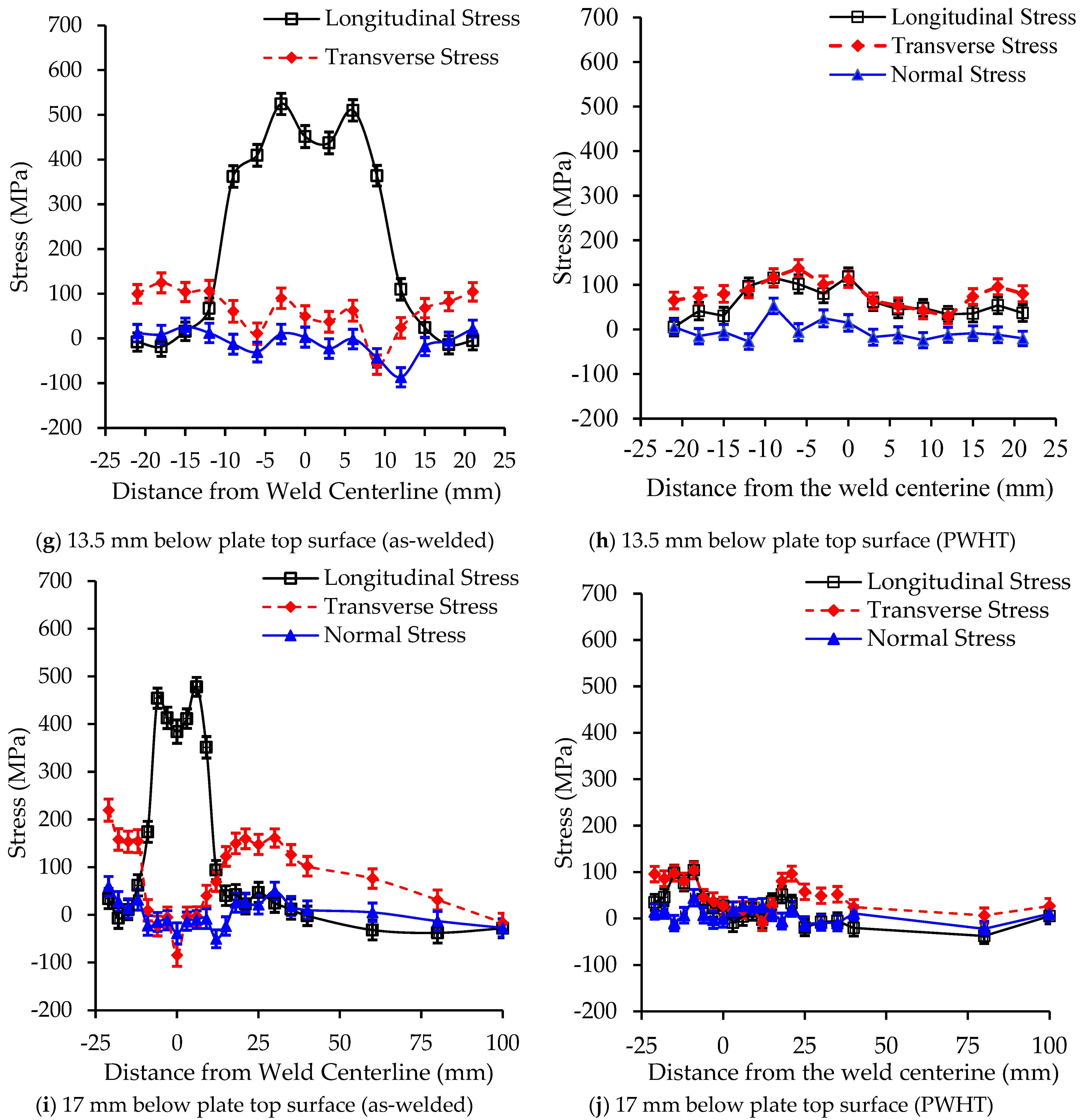
3.1. Neutron Diffraction Measurements

The non-uniform temperature distribution and differential cooling rates during welding are responsible for the formation of residual stresses and distortion on cooling. The cooling rate and thermal gradients experienced by the material in the weld and in the vicinity of the weld control the microstructure via grain size and phase transformation kinetics. These effects, in addition to thermal contraction effects, have a major contribution to the development of residual stresses.
Figure 3a–j show the residual stress distributions across the weld (3 mm, 6.5 mm, 10 mm, 13.5 mm and 17 mm below the weld top surface) for the as-welded and heat-treated specimens. The highest magnitude of residual stress, slightly lower than the yield strength of both the parent and weld metals, was found at 6.5 mm below the weld top surface at 3 mm away from the centre of the weld for the as-welded specimen (Figure 3c). The residual stress distribution in and around the weld (in the as-welded condition) reflected the thermal history of each location, with the lower part of the weld showing lower stresses due to the tempering effect of subsequent passes. The peak residual stress in the weld centreline at 6.5 mm was indicative that the final passes were ineffective at tempering this region (to be discussed further with the hardness results). In addition, residual stresses at the centre line were generally lower than in the fusion zone and heat-affected zone due to higher cooling rates experienced in these regions compared to the centreline. The longitudinal residual stresses were symmetric with respect to the weld centreline (x = 0, as shown in Figure 2), which was due to consistency in the welding process/parameters and the similar thermal fields experienced on either side of the weld centreline. The stress profile was also similar to the classic stress profile as shown in the published literature [34].
The magnitude of residual stresses in the transvers direction was significantly lower than the longitudinal direction due to lower restraint imposed in the direction perpendicular to the weld direction. This finding is consistent with the previous studies for different weld configurations [34,35,36].
A significant reduction in the residual stress was observed after PWHT, where the highest magnitude of residual stress was about 145 ± 15 MPa in the longitudinal direction, which was about 23% of the yield strength of the WM (the yield strength of the PM and WM were 650 and 710 MPa, respectively, as per tensile tests conducted at The University of Adelaide). This also confirmed the effectiveness of the applied heat treatment in mitigating the residual stresses in the welded joint. Note that the magnitude of residual stresses in the normal direction were between +90 and −120 MPa for the as-welded and heat-treated specimens, as shown in Figure 3a–j.

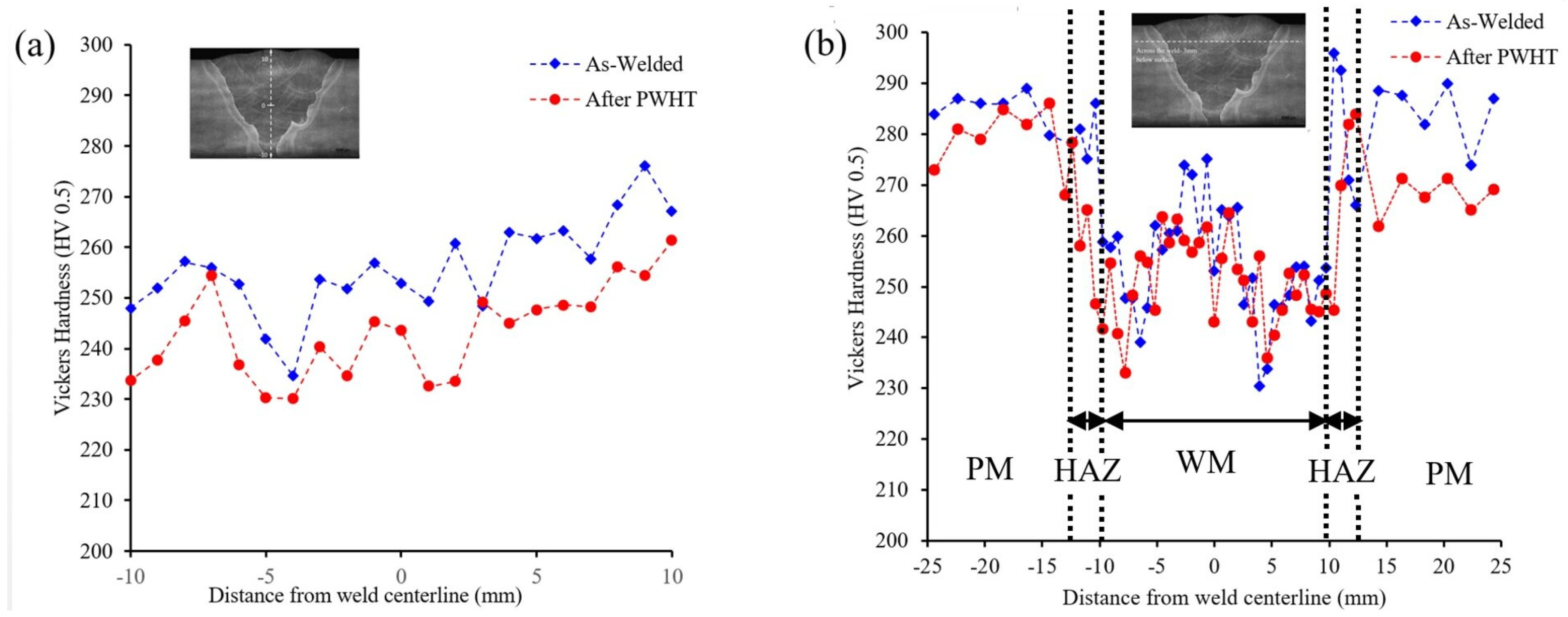
3.2. Hardness Measurements

Hardness measurements were conducted for the as-welded and heat-treated specimens, as shown in Figure 4. Measurements were performed through thickness of the weld metal (weld centreline) and across the weld at 3 mm below the top surface of the plate, a similar region where the neutron diffraction measurements were taken. Some fluctuations in the hardness values were observed, specifically for the as-welded specimen, with the higher hardness values in the HAZ in comparison with the WM and PM. However, lower hardness values could be seen for the heat-treated specimen, which is in line with the stress distribution presented in Figure 3. The microstructural changes during welding and PWHT were also expected to play an important role in the mechanical properties of weld joints, which are discussed in the following section.
The through-thickness hardness values showed a generally increasing hardness from the root of the weld to the surface in both the as-welded and PWHT samples. In the case of the as-welded sample, this diverged somewhat from the residual stress measurements in that no peak was observed at 6.5 mm. This indicated that while tempering by subsequent passes is important in the final residual stress, geometry also plays a roll. That is, the peak residual stress observed at 6.5 mm below the surface was due to both a lack of tempering and the constraint on the solidifying/cooling weld. At 3 mm, close to the free surface, there was reduced constraint, and hence the measured residual stresses were lower.

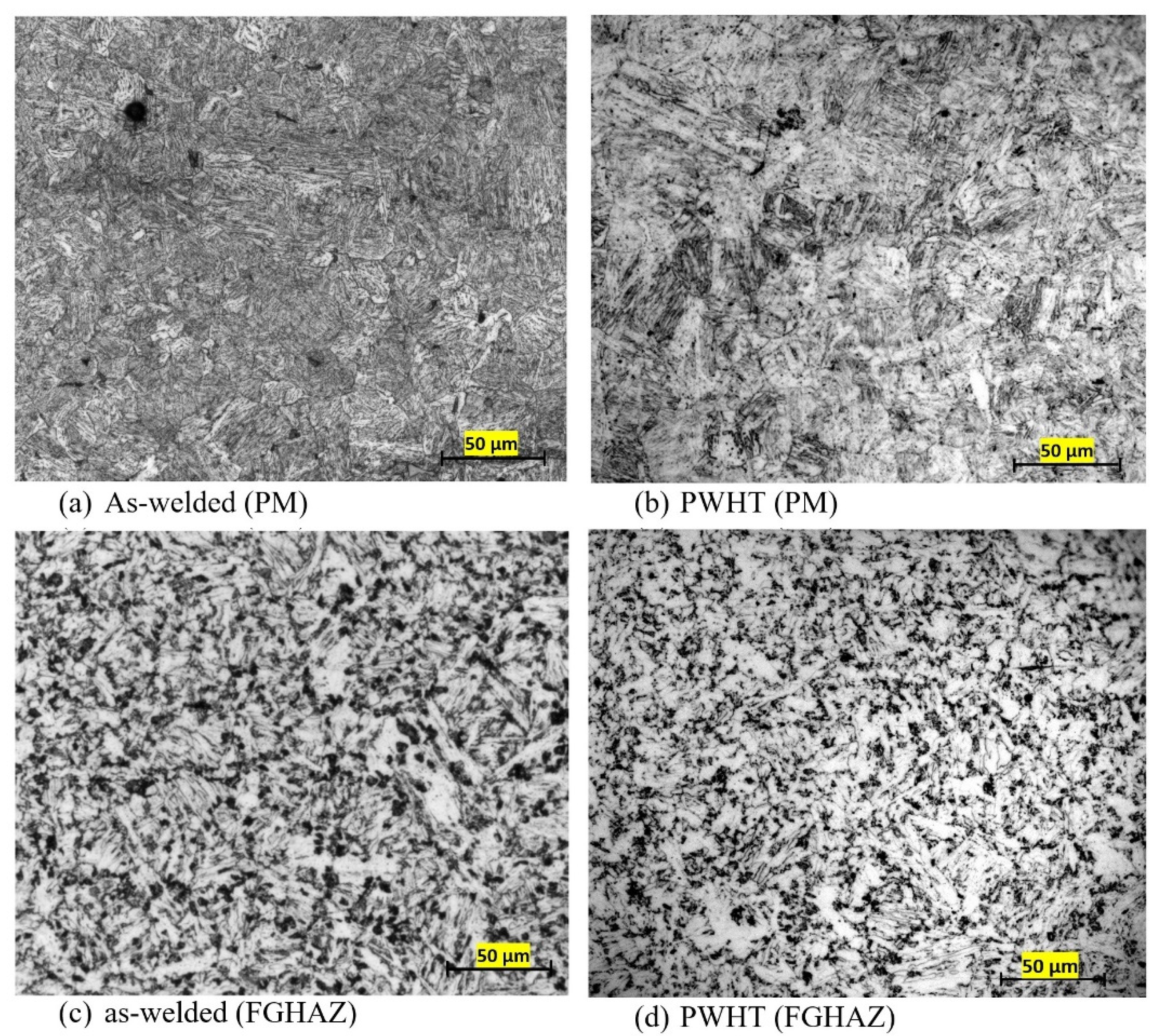
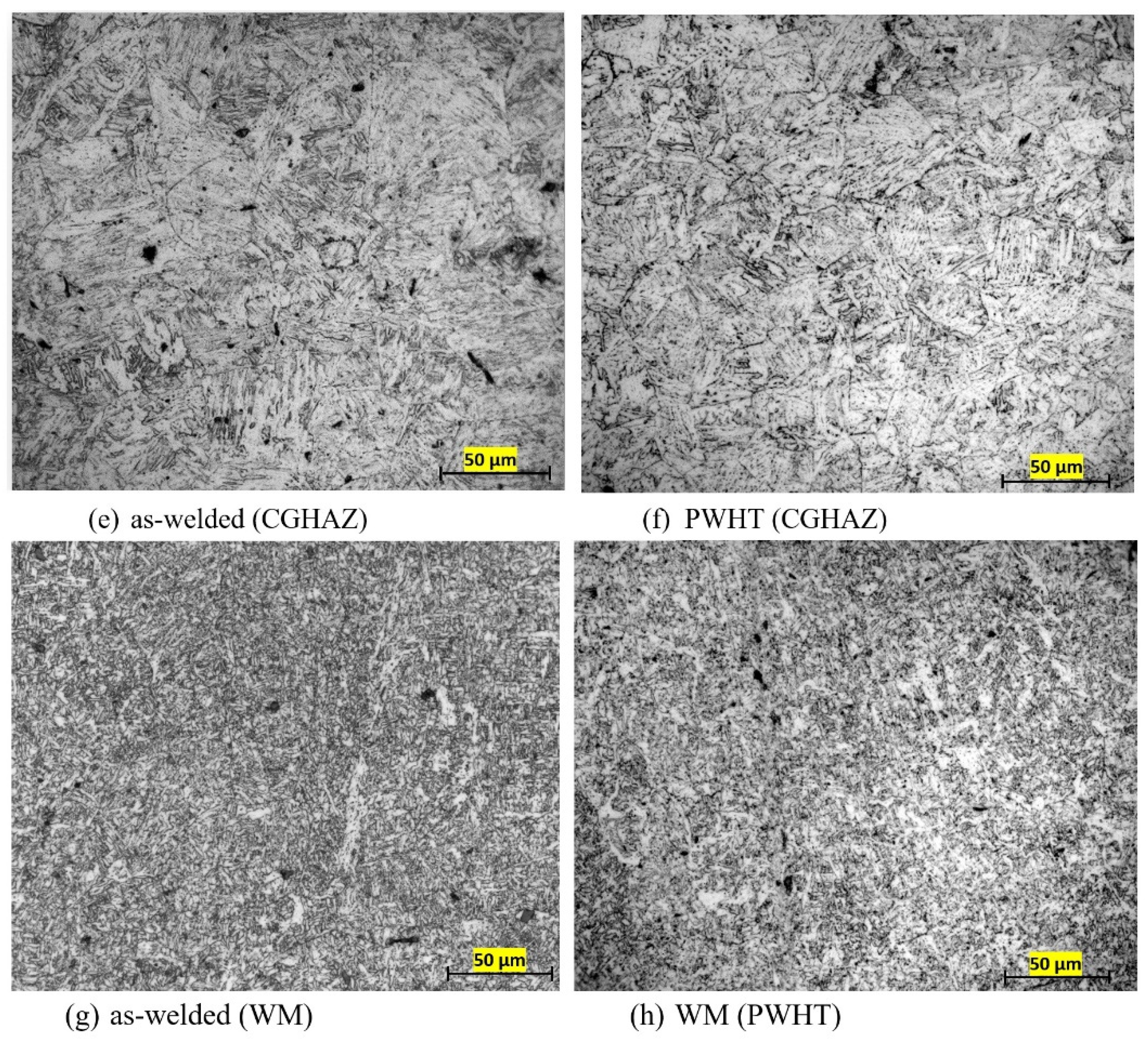
3.3. Microstructural Characterization

The fine-grained microstructure of the as-received Bisalloy 80 was mainly granular bainite, as shown by the optical micrograph in Figure 5a. The coarsening of the bainitic ferrite laths as well as the average grain size is noticeable in Figure 5b when the PM was exposed to 600 °C for 1 h during PWHT. The HAZ in the welded sample, however, develops a mainly ferritic–pearlitic structure with some residual bainitic grains of the PM (Figure 5c). The formation of pearlite may suggest the HAZ temperature has increased above the eutectoid temperature during welding, enabling the formation of ferrite and pearlite within the fine grained HAZ (FGHAZ) region. The morphology of ferrite resembles that of bainitic lath with clear coarsening. The applied PWHT, however, ensures the formation of coarsened polygonal ferrite grains and the pearlite colonies (Figure 5d). The coarse-grained HAZ (CGHAZ) region showed large bainitic grains in the as-weld structure, as seen in Figure 5e, although some Widmanstätten ferrite may have been detected. The formation of large granular bainitic ferrite grains was clear for the PWHT samples. There were also some isolated ferrite phase particles detectable in Figure 5f. The weld metal microstructure was mainly acicular ferrite with some Widmanstätten ferrite (Figure 5g). During PWHT, the formation of polygonal ferrite was evident, while the acicular ferrite was slightly coarsened. There was a small amount of mixed phases and a black region, which could be carbide.
The formation of microconstituent phases was consistent with the changes in hardness, as seen in Figure 4b, where the higher hardness in the regions near the fusion zone when compared to the centre of the weld could be attributed to the presence of Widmanstätten ferrite and bainite (Figure 5e) in the as-welded sample, which is indicative of the higher cooling rate in this region during the welding process. This finding is in-line with the residual stress measurements where higher levels of tensile residual stresses in the as-welded specimen may be associated with the formation of harder phases such as Widmanstätten ferrite and bainite in the regions near the fusion zone of the as-welded specimen. These microstructures also account for the higher hardness values measured in the WM and HAZ for the as-welded sample as opposed to the PWHT sample.

4. Conclusions

The effects of PWHT on the residual stresses, microstructure and mechanical properties of the quenched and tempered steel welds are investigated in the present study. The key findings of this study were:
(1)
A high magnitude of tensile residual stresses was found in the as-welded specimens (a maximum of 642 ± 24 MPa), which was significantly reduced after PWHT (about 145 ± 21 MPa).
(2)
There were some levels of softening related with the tempering effects in the FGHAZ of the as-welded sample, as indicated by the hardness measurements where there was a drop in the hardness values as compared with the PM. There was, however, an increase in the hardness values in the fusion zone due to steep thermal gradients at this region, which resulted in higher cooling rates when the weld pool solidified. The existence of high hardness values in this region was associated with the formation of harder phases such as Widmanstätten ferrite and bainite for the as-welded specimens.
(3)
The multi-pass welding had tempering effects, particularly from the mid-thickness weld passes toward the root passes of the as-welded plate, where lower hardness values and a reduction in the residual stresses were observed. However, it is also clear from the results presented that the development of residual stresses is also dependent on the weld geometry.
(4)
High hardness values were found particularly in the HAZ of the as-welded specimen, which was reduced after PWHT. This finding is consistent with the residual stress measurements, where a significant reduction in residual stress was found after PWHT.
(5)
The applied PWHT led to microstructural changes in the PM, HAZ and WM. These changes included formation of coarsened polygonal ferrite grains and coarsening of the bainitic ferrite laths after PWHT. Again, these findings are consistent with the reduction in the magnitude of residual stress and lower hardness values, particularly in the HAZ and WM of the heat-treated specimen.

Author Contributions

Conceptualization, H.A. and R.G.; methodology, H.A.; validation, H.A. and A.P.; formal analysis, H.A.; experimental investigation, H.A., A.P. and M.R.; resources, R.G., A.P. and M.R.; data curation, H.A.; writing—original draft preparation, H.A.; writing—review and editing, R.G., M.R. and A.P.; visualization, H.A.; supervision, R.G. and A.P.; project administration, H.A., A.P. and M.R.; funding acquisition, R.G. and A.P. All authors have read and agreed to the published version of the manuscript.

Funding

Australian Nuclear Science and Technology Organisation (Grant number: P7087).

Institutional Review Board Statement

Not applicable.

Informed Consent Statement

Not applicable.

Acknowledgments

The neutron diffraction analysis was performed at the Kowari strain scanner (ANSTO) through a facilities access award P7087. The welding was carried out at Australian Welding Solutions (AWS), and the Mechanical Engineering workshop at Adelaide University. We would like to acknowledge with gratitude the support of Neville Cornish (AWS, for provision of welding facilities at AWS) and Pascal Symons (Adelaide University) who has performed the welding at AWS and Adelaide University.

Conflicts of Interest

The authors declare no conflict of interest.

References

  1. Balakrishnan, M.; Balasubramanian, V.; Reddy, G.M. Effect of joint design on ballistic performance of quenched and tempered steel welded joints. Mater. Des. 2014, 54, 616–623. [Google Scholar] [CrossRef]
  2. Ryan, S.; Li, H.J.; Edgerton, M.; Gallardy, D.; Cimpoeru, S.J. Ballistic Evaluation of an Australian Ultra-High Hardness Steel. In Proceedings of the 29th International Symposium on Ballistics, BALLISTICS, Edinburgh, Scotland, 9–13 May 2016; DEStech Publications, Inc.: Lancaster, PA, USA, 2016; pp. 1773–1778. [Google Scholar]
  3. Clark, H.M.; Llewellyn, R.J. Assessment of the erosion resistance of steels used for slurry handling and transport in mineral processing applications. Wear 2001, 250, 32–44. [Google Scholar] [CrossRef]
  4. Ade, F. Ballistic Qualification of Armor Steel Weldments. Weld. J. 1991, 70, 53–58. [Google Scholar]
  5. Magudeeswaran, G.; Balasubramanian, V.; Reddy, G.M.; Balasubramanian, T.S. Effect of welding processes and consumables on tensile and impact properties of high strength quenched and tempered steel joints. J. Iron Steel Res. Int. 2008, 15, 87–94. [Google Scholar] [CrossRef]
  6. Magudeeswaran, G.; Balasubramanian, V.; Reddy, G.M. Hydrogen induced cold cracking studies on armour grade high strength, quenched and tempered steel weldments. Int. J. Hydrog. Energy 2008, 33, 1897–1908. [Google Scholar] [CrossRef]
  7. Magudeeswaran, G.; Balasubramanian, V.; Reddy, G.M. Effect of welding processes and consumables on fatigue crack growth behaviour of armour grade quenched and tempered steel joints. Def. Technol. 2014, 10, 47–59. [Google Scholar] [CrossRef]
  8. Falkenreck, T.; Kromm, A.; Böllinghaus, T. Investigation of physically simulated weld HAZ and CCT diagram of HSLA armour steel. Weld. World 2018, 62, 47–54. [Google Scholar] [CrossRef]
  9. Hochhauser, F.; Ernst, W.; Rauch, R.; Vallant, R.; Enzinger, N. Influence of the soft zone on the strength of welded modern HSLA steels. Weld. World 2012, 56, 77–85. [Google Scholar] [CrossRef]
  10. Hanhold, B.; Babu, S.S.; Cola, G. Investigation of heat affected zone softening in armour steels Part 1—Phase transformation kinetics. Sci. Technol. Weld. Join. 2013, 18, 247–252. [Google Scholar] [CrossRef]
  11. Hanhold, B.; Babu, S.S.; Cola, G. Investigation of heat affected zone softening in armour steels Part 2—Mechanical and microstructure heterogeneity. Sci. Technol. Weld. Join. 2013, 18, 253–260. [Google Scholar] [CrossRef]
  12. Kovacevic, R. Hybrid Laser-GMAW Welding of High Strength Quenched-Tempered Steels. Rare Met. Mater. Eng. 2011, 40, 102–105. [Google Scholar]
  13. Górka, J.; Kotarska, A. MAG welding of 960QL quenched and tempered steel. In Proceedings of the IOP Conference Series: Materials Science and Engineering, Lasi, Rommania, 19–22 June 2019; IOP Publishing: Bristol, UK, 2019; Volume 591, p. 012017. [Google Scholar]
  14. Yurioka, N.; Suzuki, H. Hydrogen assisted cracking in C-Mn and low alloy steel weldments. Int. Mater. Rev. 1990, 35, 217–249. [Google Scholar] [CrossRef]
  15. Costin, W.L.; Lavigne, O.; Kotousov, A.; Ghomashchi, R.; Linton, V. Investigation of hydrogen assisted cracking in acicular ferrite using site-specific micro-fracture tests. Mater. Sci. Eng. A 2016, 651, 859–868. [Google Scholar] [CrossRef]
  16. Kurji, R.; Lavigne, O.; Ghomashchi, R. Micromechanical characterisation of weld metal susceptibility to hydrogen-assisted cold cracking using instrumented indentation. Weld. World 2016, 60, 883–897. [Google Scholar] [CrossRef]
  17. Alipooramirabad, H.; Paradowska, A.M.; Ghomashchi, R.; Kotousov, A.; Hoye, N. Prediction of welding stresses in WIC test and its application in pipelines. Mater. Sci. Technol. 2016, 32, 1462–1470. [Google Scholar] [CrossRef]
  18. Alipooramirabad, H.; Paradowska, A.; Lavigne, O.; Ghomashchi, R.; Reid, M. In situ neutron diffraction measurement of strain relaxation in welds during heat treatment. Sci. Technol. Weld. Join. 2017, 22, 484–495. [Google Scholar] [CrossRef]
  19. Alipooramirabad, H.; Paradowska, A.; Ghomashchi, R.; Reid, M. Investigating the effects of welding process on residual stresses, microstructure and mechanical properties in HSLA steel welds. J. Manuf. Processes 2017, 28, 70–81. [Google Scholar] [CrossRef]
  20. Kuzmikova, L. An Investigation of the Weldability of High Hardness Armour Steels. Ph.D. Thesis, University of Wollongong, Wollongong, Australia, 2013. [Google Scholar]
  21. Jo, M.C.; Kim, S.; Suh, D.W.; Kim, H.K.; Kim, Y.J.; Sohn, S.S.; Lee, S. Enhancement of ballistic performance enabled by transformation-induced plasticity in high-strength bainitic steel. J. Mater. Sci. Technol. 2021, 84, 219–229. [Google Scholar] [CrossRef]
  22. Kaplan, D.; Murry, G. Thermal, Metallurgical and Mechanical Phenomena in the Heat Affected Zone. Metall. Mech. Weld. Process. Ind. Appl. 2008, 1, 89–131. [Google Scholar]
  23. Zhao, M.S.; Chiew, S.P.; Lee, C.K. Post weld heat treatment for high strength steel welded connections. J. Constr. Steel Res. 2016, 122, 167–177. [Google Scholar] [CrossRef]
  24. Saini, N.; Mulik, R.S.; Mahapatra, M.M. Influence of filler metals and PWHT regime on the microstructure and mechanical property relationships of CSEF steels dissimilar welded joints. Int. J. Press. Vessel. Pip. 2019, 170, 1–9. [Google Scholar] [CrossRef]
  25. Sparkes, D.J.; Bailey, N.; Gooch, T.G. Effect of post-weld heat treatment on heat affected zone microstructures of microalloyed C–Mn submerged arc welds. Mater. Sci. Technol. 1990, 6, 1215–1226. [Google Scholar] [CrossRef]
  26. Sterjovski, Z.; Dunne, D.P.; Ambrose, S. Evaluation of cross-weld properties of quenched and tempered pressure vessel steel before and after PWHT. Int. J. Press. Vessel. Pip. 2004, 81, 465–470. [Google Scholar] [CrossRef]
  27. Sterjovski, Z.; Carr, D.G.; Dunne, D.P.; Ambrose, S. Effect of PWHT cycles on fatigue crack growth and toughness of quenched and tempered pressure vessel steels. Mater. Sci. Eng. A 2005, 391, 256–263. [Google Scholar] [CrossRef]
  28. AS/NZS 3992:2015; Australian/New Zealand Standard AS/NZS 3992-Welding and Brazing Qualification, Sections 3 and 7. Standards Australia International Ltd.: Strathfield, Australia, 2015.
  29. Alipooramirabad, H.; Paradowska, A.; Nafisi, S.; Reid, M.; Ghomashchi, R. Post-Weld Heat Treatment of API 5L X70 High Strength Low Alloy Steel Welds. Materials 2020, 13, 5801. [Google Scholar] [CrossRef]
  30. AS 2205.6.1-2003; Methods for Destructive Testing of Welds in Metal—Weld Joint Hardness Test. Standards Australia: Sydney, Australia, 2003.
  31. Alipooramirabad, H.; Paradowska, A.; Reid, M.; Ghomashchi, R. Effect of holding time on strain relaxation in high-strength low-alloy steel welds: An in-situ neutron diffraction approach. J. Manuf. Processes 2022, 73, 326–339. [Google Scholar] [CrossRef]
  32. Roy, T.; Paradowska, A.; Abrahams, R.; Law, M.; Mutton, P.; Soodi, M.; Yan, W. Residual stress in laser cladded heavy-haul rails investigated by neutron diffraction. J. Mater. Process. Technol. 2020, 278, 116511. [Google Scholar] [CrossRef]
  33. Allen, A.J.; Hutchings, M.T.; Windsor, C.G.; Andreani, C. Neutron diffraction methods for the study of residual stress fields. Adv. Phys. 1985, 34, 445–473. [Google Scholar] [CrossRef]
  34. Ueda, Y.; Murakawa, H.; Ma, N. Welding Deformation and Residual Stress Prevention; Elsevier: Amsterdam, The Netherlands, 2012; ISBN 0123948045. [Google Scholar]
  35. Paradowska, A.; Price, J.W.H.; Ibrahim, R.; Finlayson, T. A neutron diffraction study of residual stress due to welding. J. Mater. Process. Technol. 2005, 164, 1099–1105. [Google Scholar] [CrossRef]
  36. Zhan, Y.; Liu, C.; Kong, X.; Lin, Z. Experiment and numerical simulation for laser ultrasonic measurement of residual stress. Ultrasonics 2017, 73, 271–276. [Google Scholar] [CrossRef]
Figure 1. (a) Welded plate of Bisalloy 80 steel. (b) Schematic diagram to show the clamp locations at the back of plates used during welding of the samples (note: the rolling direction of the plate is perpendicular to the welding direction).
Metals 12 01569 g001
Figure 2. Optical macrograph of the weld joint showing the neutron diffraction stress measurement locations (dashed lines).
Metals 12 01569 g002
Figure 3. Longitudinal, transverse and normal residual stress distribution across the weld from 3 mm (a,b); (c,d) 6.5 mm; (e,f) 10 mm; (g,h) 13.5 mm; and (i,j) 17 mm, from the top surface for the as-welded and PWHT specimens.
Metals 12 01569 g003aMetals 12 01569 g003bMetals 12 01569 g003c
Figure 4. Microhardness distribution for the as-welded and PWHT specimens (a) through the thickness at the centreline, and (b) 3 mm below the surface across the weld.
Metals 12 01569 g004
Figure 5. Optical micrographs showing the PM, FGHAZ, CGHAZ and WM in the as-welded (a,c,e,g) and after PWHT (b,d,f,h) specimens.
Metals 12 01569 g005aMetals 12 01569 g005b
Table 1. Chemical composition for 20 mm Bisalloy 80 steel plate and the consumable wire.
MaterialsCMnSiPSNiCrMoCuAlSnTiBFe
Bisalloy plate0.171.370.210.180.040.0170.200.200.0260.0350.0020.0190.002Balance
Consumable wire-1.50.40.0150.012.20.150.40.15----Balance
Table 2. Welding (GMAW-P) parameter and specifications.
DirectionFlat (1G)
Diameter of Wire1.2 mm
Electrode Class (AWS)A5.28
SpecificationER 110S-G
PolarityDC+
Shielding GasAr 18% Co2 (15–20 L/min)
Current135–225 A
Voltage21–30 V
Travel Speed170–400 mm/min
Heat Input Range0.48–2.19 kJ/mm
Pre Heat Range25 °C
Deposition ModeGMAW-P (ISO 857 Process No.13)
Publisher’s Note: MDPI stays neutral with regard to jurisdictional claims in published maps and institutional affiliations.

