Article

Evolution of Microstructures, Texture and Mechanical Properties of Al-Mg-Si-Cu Alloy under Different Welding Speeds during Friction Stir Welding

1
School of Mechanical and Automotive Engineering, Guangxi University of Science and Technology, Liuzhou 545006, China
2
Guangxi Earthmoving Machinery Collaborative Innovation Center, Liuzhou 545006, China
3
Guangxi Key Laboratory of Automobile Components and Vehicle Technology, Liuzhou 545006, China
*
Authors to whom correspondence should be addressed.
Metals 2023, 13(6), 1120; https://doi.org/10.3390/met13061120
Submission received: 5 April 2023 / Revised: 1 June 2023 / Accepted: 9 June 2023 / Published: 14 June 2023

Abstract

:
The effects of different welding speeds on the microstructures and mechanical properties of Al-0.75Mg-0.75Si-0.8Cu alloys were investigated using optical metallographic microscopy (OM), X-ray diffraction (XRD) analysis, an ETM105D electronic universal testing machine and field emission electron microscopy (SEM). The results reveal that during the friction stir welding process, the welded joint forms the base material (BM), heat-affected zone (HAZ), thermomechanically affected zone (TMAZ) and nugget zone (NZ), under the action of shear force and friction heat. The textures present in the BM are mainly C ({001}<100>) recrystallised cubic texture and P({110}<112>) recrystallised texture, Goss (G) texture, brass (B) texture and {112}<110> rotating copper texture. The organisation of the NZ undergoes dynamic recrystallisation, forming fine isometric crystals with large angular grain boundaries, accounting for more than 75% of the total. The geometrically necessary dislocations (GNDs) in the NZ grow as the welding speed rises. Moreover, {111}<1 1 0> and {111}< 1 10 > shearing textures, {001}<110> recrystallisation textures and fibre textures are mainly present in NZs. The average grain size in the NZ was the smallest, and the mechanical properties were the best at a welding speed of 125 mm/min. The grain size and the tensile strength and elongation of the NZ were 2.945 µm, 200.7 MPa and 12.7% for the joint at a welding speed of 125 mm/min, respectively.

1. Introduction

Al-Mg-Si-Cu alloys (6×××× series aluminium alloys) have the advantages of high specific strength, good welding properties and high corrosion resistance, and are widely used in construction, automotive, aerospace and other fields [1]. The conventional fusion welding process produces defects, such as porosity and thermal cracking, when welding aluminium alloys, which seriously affects the overall performance of the welded joints [2]. Unlike the fusion welding process, friction stir welding (FSW) does not produce defects, such as porosity and cracks, during the welding process and does not produce harmful gases such as fumes, which is a new green and non-polluting solid phase welding technology. Studies have shown that suitable FSW welding process parameters can effectively improve the grain organisation of welded joints and improve the performance of welded joints [3,4,5].
In stir friction welding, the metal material will accumulate on the advancing side with the shear rotation of the stirring needle, and different regions are subjected to different thermal coupling, which will make the tissue distribution of the welded joint uneven and form different grains and textures, directly affecting the overall performance of the welded joint. Therefore, it is very important to study the microstructure, texture evolution and mechanical properties of welded joints under different welding process parameters. Jing et al. [6] found that by increasing the welding speed of 6063-T6 aluminium alloy, the mechanical properties of the joint first increased and then decreased, and the fracture location was mostly located in the heat-affected zone of the backwards side. Jin et al. [7] studied the fracture forms of 7055 aluminium alloy joints at different rotational speeds, and the results showed that with increasing rotational speed, the fracture position of the joints first transferred from the HAZ to the NZ, resulting in an “S”-shaped fracture, and then transferred to the thermomechanically affected zone on the advancing side (AS-TMAZ), resulting in fracture. Dong et al. [8] studied the welding speed on the 6005A-T6 aluminium alloy organisation and hardness and found that the original β” phase in the weld nucleus zone completely entered the α-Al matrix, and the lower welding speed promoted the formation of the GP zone, thereby increasing the hardness of the HZs. The welding speed on the TMAZ hardness was not significant, and the evolution of the precipitation phase was mainly related to the peak temperature. The HAZ due to β” and Q” phase aggregation coarsening had the lowest hardness, and the hardness of the HAZ gradually increased with increasing welding speed. Ding et al. [9] investigated the influence of welding speed on the microstructure development and mechanical characteristics of the NZ made of Al-Mg-Mn-Zr-Ti alloy. It was discovered that when the welding speed increased, the DRX grains in the NZ decreased, with no significant texture and low texture strength. The mechanical properties of the welded joints first increased and then decreased. Yuan et al. [10] studied the crystal orientation of the NZ of 5083 aluminium alloy and found that the brass texture and S texture were mainly present in the BM, while these two types of texture were basically absent in the NZ, so the NZ is a weakly oriented organization. Zhang et al. [11] studied the evolution of crystal texture components in different regions of the NZ of 6082-T6 aluminium alloy and found that the {111} < 1 10 > shear texture and {001}<100> recrystallised cubic texture mainly existed in the backwards side of the NZ. More thermoplastic deformation occurred in the middle of the NZ, thus {111} < 1 10 > the shear texture became more prominent, and the {001}<100> texture transformed into a {001}<110> rotating cubic texture; on the advancing side of the NZ, the {111} < 1 10 > texture and {001}<110> texture rotated in the ND direction, forming the {111} < 1 10 > shear texture and {001}<100> cubic texture. Although a large number of scholars have conducted a lot of research on stir friction welding of aluminium alloys, no one has studied the stir friction welding of the Al-0.75Mg-0.75Si-0.8Cu alloy. Therefore, in the present work, the microstructure, texture evolution and mechanical properties are studied in the NZ of FSW joints made from Al-0.75Mg-0.75Si-0.8Cu alloys at different welding speeds (υ) and a constant rotation speed (ω), i.e., ω = 750 r/min; υ = 75, 100, 125, 150 mm/min, to provide a theoretical basis for the practical application of FSW welding.

2. Experimental Materials and Methods

The material used for the experiments was an Al-0.75Mg-0.75Si-0.8Cu alloy ingot. The industrial, pure aluminium with 99.99% content and the intermediate alloy Al-10Si and Al-10Cu were placed into a resistance melting furnace at 800 °C in a certain proportion. After these materials were melted, the industrial, pure magnesium with 99.99% content in a certain proportion (considering the burning loss of pure magnesium, the content is higher than 10% of the theoretical calculation) was placed into a resistance melting furnace. The resistance furnace was turned off after melting, it was stirred and the switch of the resistance furnace was opened, the temperature was increased to 780 °C for 10 min, then lowered to 720 °C for slagging, and finally poured into a 150 mm × 100 mm × 20 mm Al-0.75Mg-0.75Si-0.8Cu alloy ingot. It was subjected to a 560 °C × 24 h homogenisation process and the ingots were, subsequently, machined into 100 mm × 80 mm × 14 mm plates by a milling machine. The plates were rolled to 4 mm by two hot rolling passes (first pass with 4 mm down and second pass with 6 mm down), both at a holding time of 400 °C/20 min, followed by a solid solution treatment at 510 °C/80 min and an ageing treatment at 190 °C/13 h, and finally cold rolled to 2 mm, both at a strain rate of 10 s−1.
Before welding, all plates were sandpapered to remove oxidation and grease. The shoulder diameter of the stirring head used for welding was 12 mm, the length of the stirring pin was 1.85 mm, the shape was conical, the large diameter of the stirring pin was 3.6 mm, the small diameter was 2.5 mm, and the welding direction (WD) was perpendicular to the rolling direction (TD). The specific welding parameters are shown in Table 1.
The size diagram of the tensile sample is shown in Figure 1. An ETM105D electronic universal testing machine was used to test the mechanical properties (tensile rate of 2 mm/min). Three tensile specimens were taken from each group, and the average value was obtained. A SmartLab type X-ray diffractometer was used to examine the texture of the specimens, with specific parameters of 40 KV Cu target rays, a scanning angle of 10–90° and a scanning speed of 2°/min. A Sigma scanning electron microscope was used to observe the fracture morphology of the welded joints. Samples were taken from the welded joints to polish the cross section (ND), and the specimens were electrochemically polished with 70% nitric acid and 30% methanol. The polishing time was 30 s. The EBSD experiments were carried out using a field emission scanning electron microscope (Sigma) with an EBSD probe (Aztec MAX80).

3. Experimental Results and Analysis
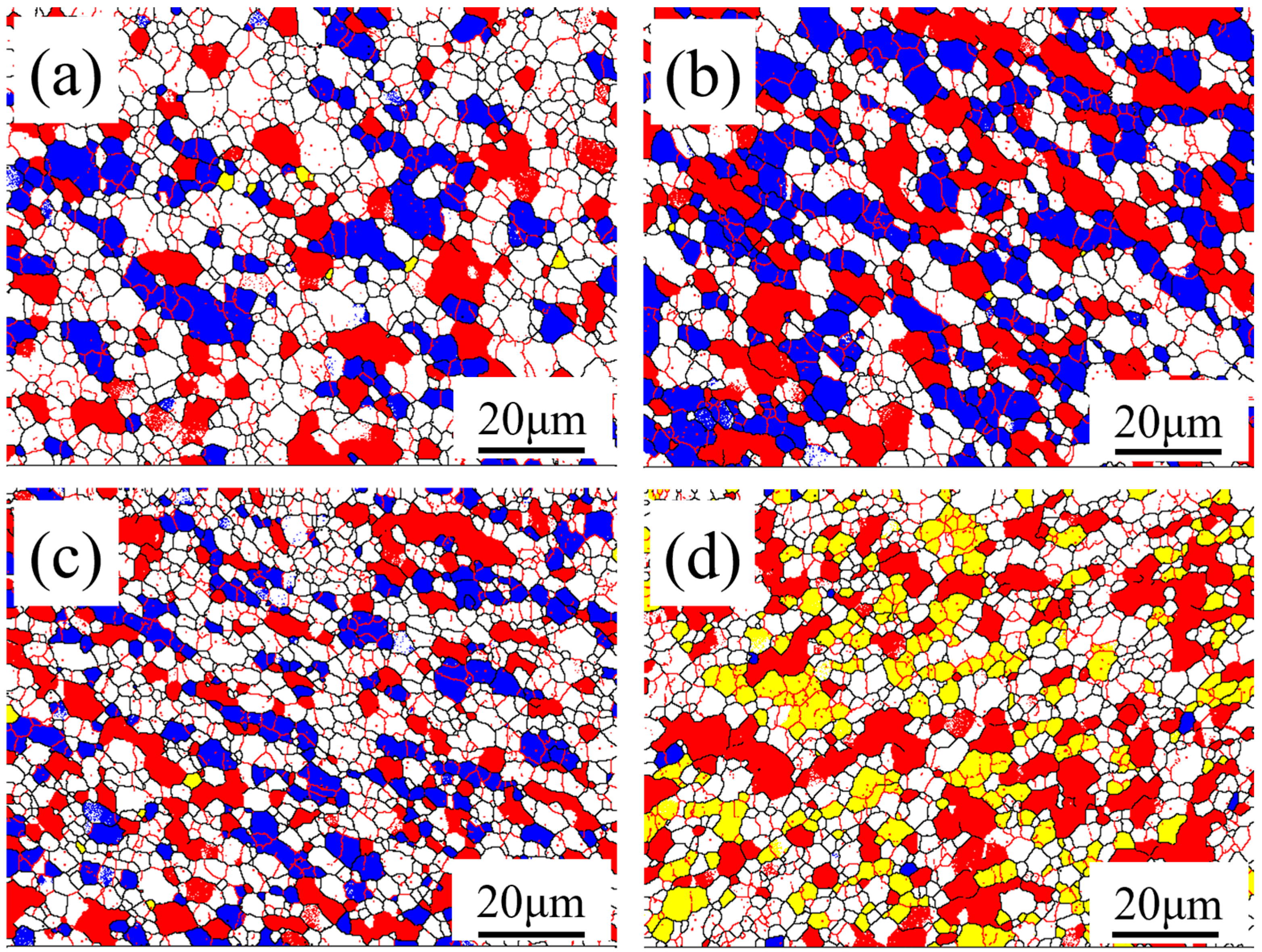
3.1. Microstructure

The microstructure of each region of the stir friction welded joint is shown in Figure 2. The BM along the rolling direction of the cross-sectional microstructure is shown in Figure 2a. The grains are fibrous and elongated along the rolling direction. The organisation in the NZ is subject to strong thermomechanical coupling, dynamic recrystallisation occurs and fine equiaxed crystals are formed. The grains in the HAZ maintain the original shape of the base material but, in the welding process, the grains become coarser as a result of frictional thermal cycling. As the peak temperature on the advancing side (AS) is higher than that on the retreating side (RS), the grain changes in the AS are more pronounced. The TMAZ undergoes plastic deformation and partial recrystallisation under the action of thermal coupling of the stirring needles, forming a microstructure consisting of curved and elongated grains. Comparing Figure 2c,e, it can be clearly found that the AS-HAZ demarcation line is more obvious, because the tissue of the AS undergoes dynamic recrystallisation under the effect of rotational shear, and the recrystallised microstructure formed is obviously different from the original BM tissue, while the tissue of the RS is mainly subject to extrusion, and the dynamic recrystallisation is limited, so the boundary between it and the NZ is not clear enough [12]. At the same time, in Figure 2e, it can also be observed that the microstructure of the thermally affected zone on the retreating side expands towards the inside of the weld nugget zone, which is due to the good fluidity of the retreating side microstructure. In Figure 2e, the expansion of the tissue in the RS-TMAZ into the inner part of the NZ can also be observed. This is due to the good fluidity of the RS tissue and the combined effect of the compression of the RS tissue by the shaft shoulder and the shearing of the stirring pin, which causes the material in the upper part of the weld to be squeezed into the NZ [13].
Figure 3 shows the EBSD figure, grain size distribution figure and grain boundary orientation angle distribution figure for the NZ at different welding speeds. Figure 3(a1–d1) includes red (2 ~ 5°) thick lines and green (5 ~ 15°) thick lines on behalf of small angle grain boundaries, and black (15 ~ 65°) thick lines on behalf of large angle grain boundaries. The tissue in the NZ is subjected to the compression of the axial shoulder and the stirring action of the stirring needle, and the original tissue undergoes intense thermomechanical coupling, so the grains in the NZ undergo dynamic recrystallisation, producing fine isometric axial grains [14]. Figure 3(a2–d2) shows the grain size distribution map derived through Channel 5 software, while the average grain size of the weld nucleus zone was calculated for the different welding speeds of 3.898 µm, 3.692 µm, 2.945 µm and 3.2 µm. The grain size with the welding speed first increased and then decreased because the welding speed increased, and the peak temperature of the welded joint decreased, thereby reducing the driving force of the grain growth; at the same time, the increase in welding speed reduced the deformation of the welded joint, which caused the grains to grow [15]. Therefore, different welding speeds have different main factors affecting the grain size [16]. At a welding speed of 75 to 125 mm/min, the peak temperature is the main factor affecting the grain size, which decreases; at a welding speed of 125 mm/min to 150 mm/min, deformation is the main factor affecting the grain size, which becomes larger. Figure 3(a3–d3) shows the distribution of the grain boundary orientation angles at different welding speeds. From the figure, the proportion of large angle grain boundaries in the NZ is more than 75%, which is because the thermoplastic deformation during the welding process introduces a large number of dislocations. In the subsequent dynamic response, a small angle grain boundary composed of subgrains will be formed. In the continuous dynamic recrystallisation process, subgrains rotate to the subgrain boundaries through repeated absorption of dislocation growth, evolving into recrystallised grains with large angle grain boundaries [17,18]. As the welding speed increases, the peak temperature of the weld nucleation zone decreases, inhibiting the recrystallisation process and decreasing the percentage of large angle grain boundaries.

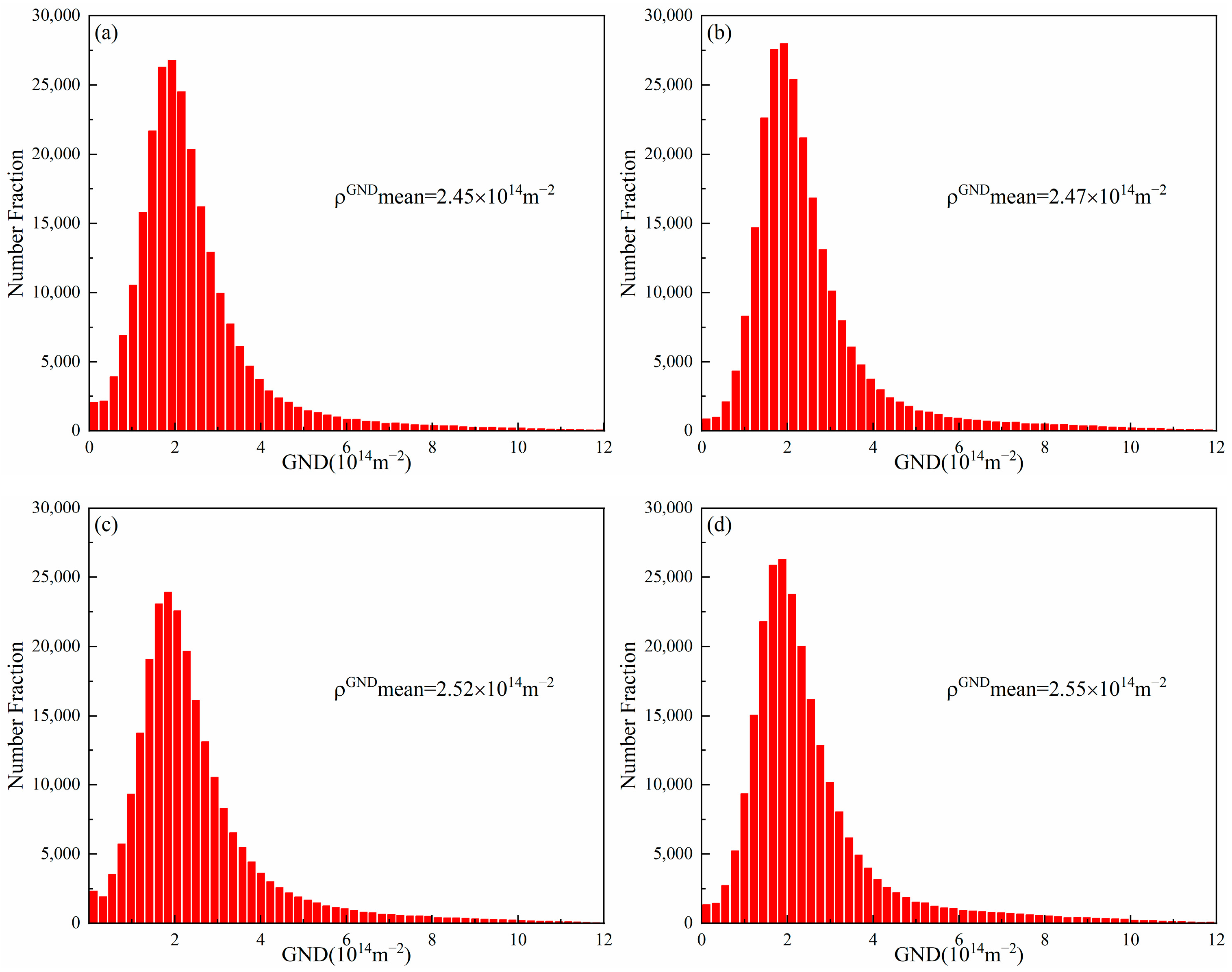
3.2. Geometrically Necessary Dislocations
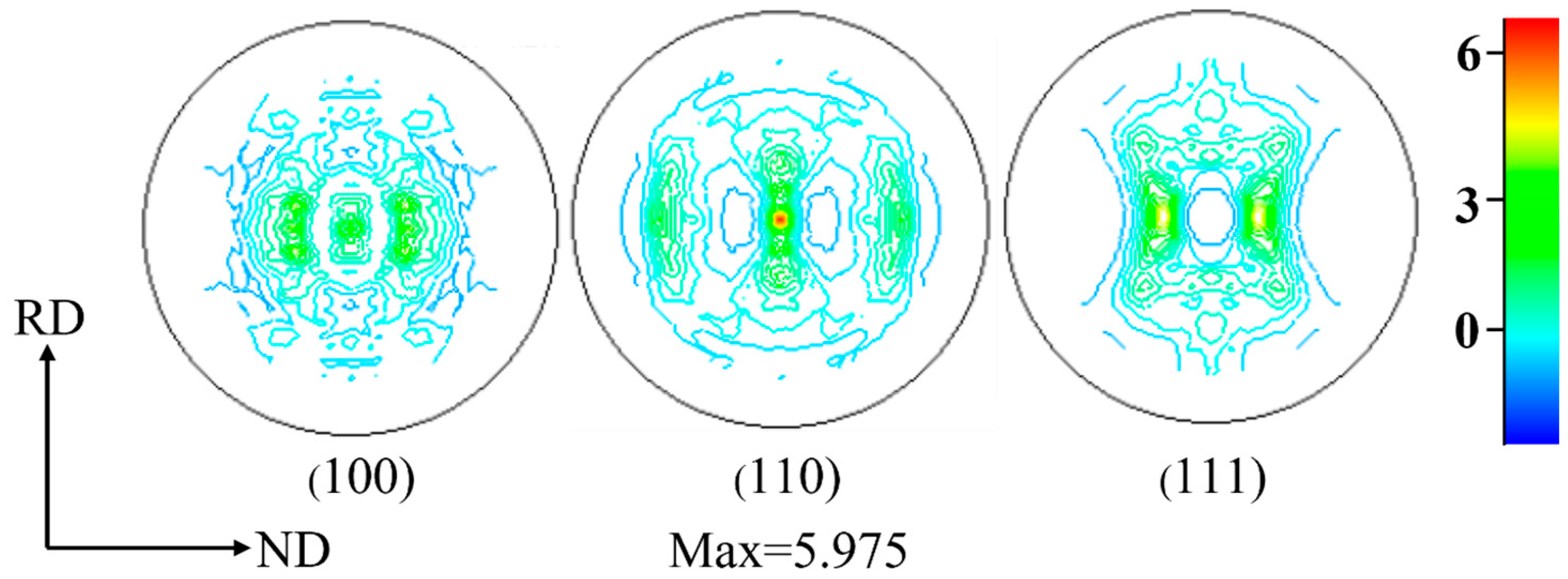
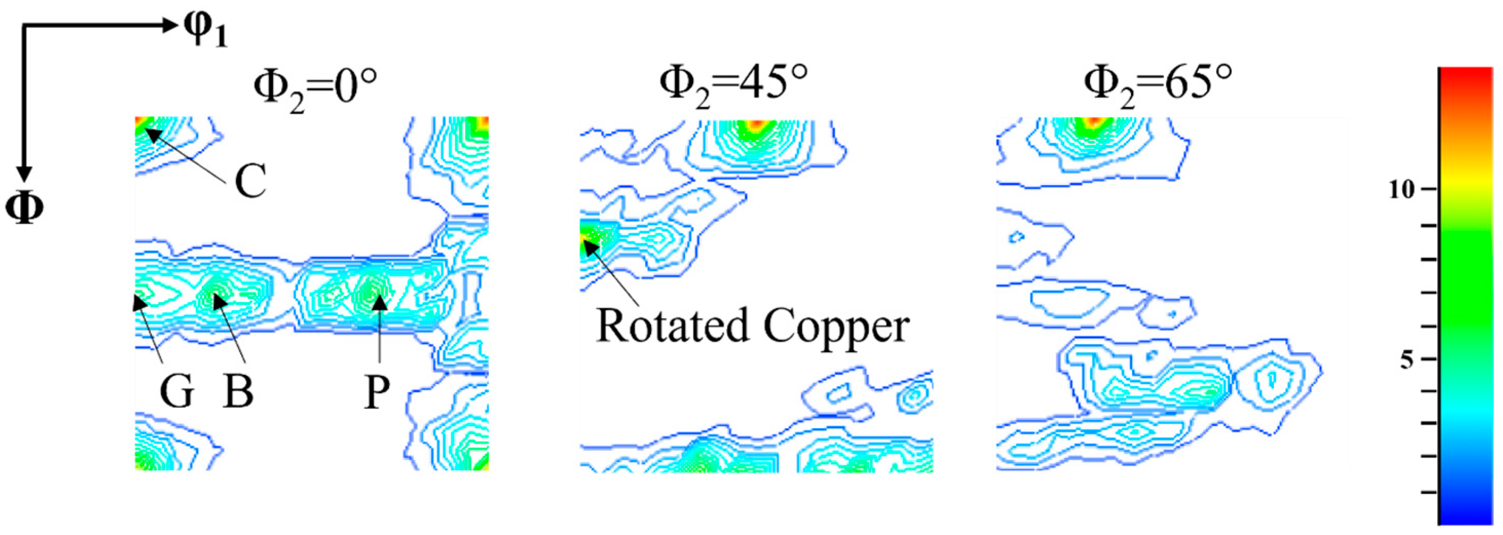
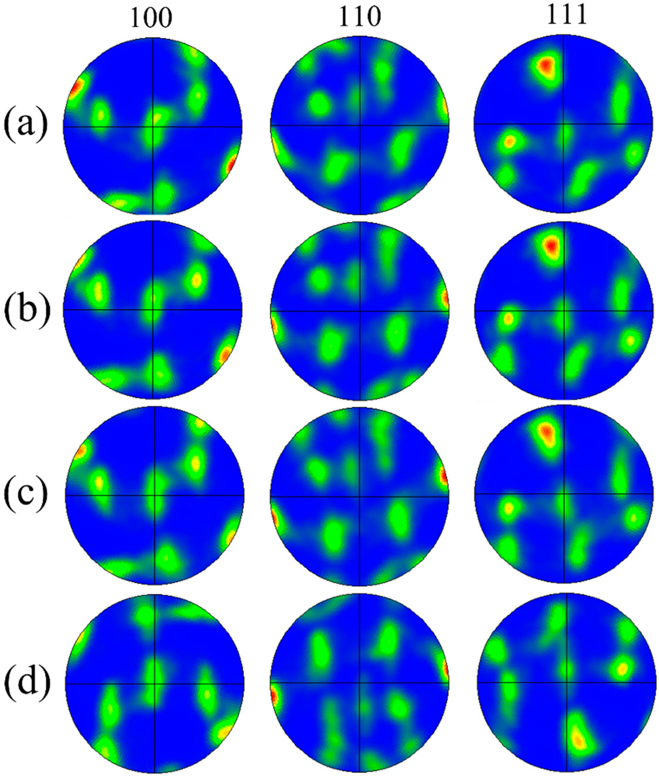
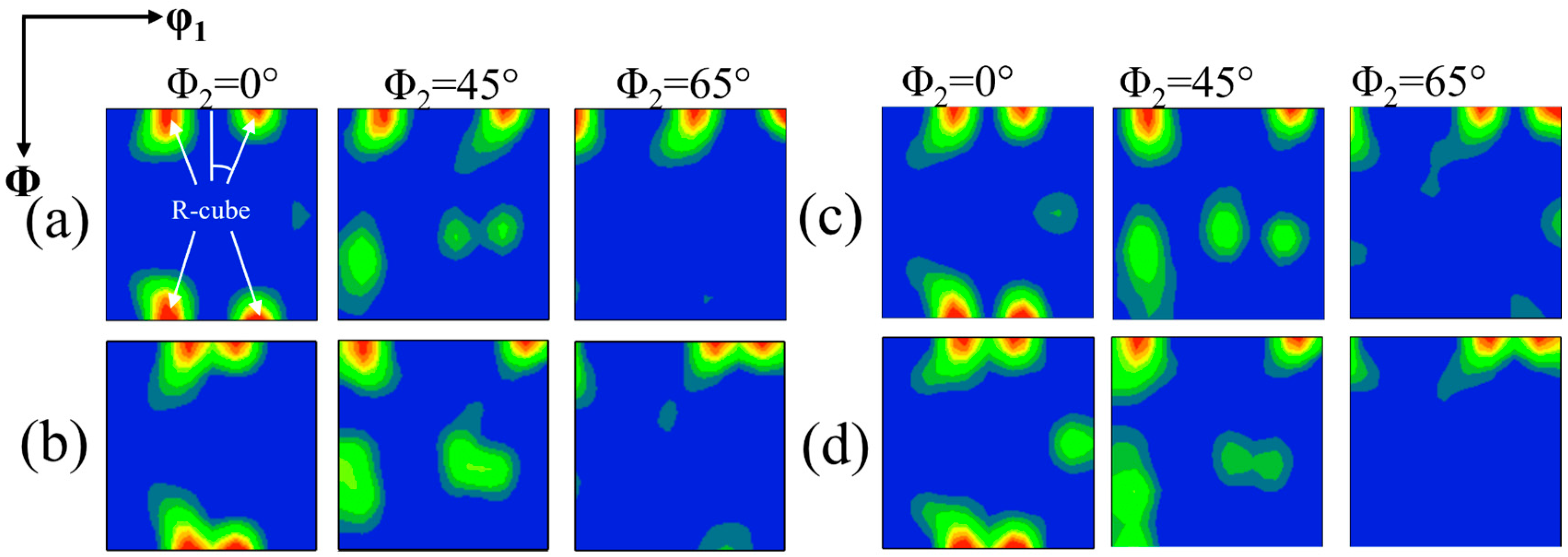
Figure 4 shows the kernel average misorientation (KAM) figure for different welding speeds, retrieved directly from the EBSD data, which was chosen as a measure for the local misorientations. The KAM quantifies the average misorientation around a measurement point with respect to a defined set of nearest or nearest plus second-nearest neighbour points [19,20]. KAM can reflect the strain energy as well as the magnitude of the dislocation density [21], which is calculated by the software for different welding speeds in the weld kernel zone. The KAM values are 0.42°, 0.43°, 0.42° and 0.43°, which indicates that the welding speed has a small effect on the KAM of the HZ. The smaller KAM values are due to the complete dynamic recrystallisation of the tissue in the NZ.
The KAM diagram can only qualitatively describe the dislocation density, and the magnitude of the KAM value can only be used to determine the change trend in the dislocation density. In this experiment, the KAM value did not change significantly with the change in welding speed, resulting in the inability to determine the effect of welding speed on dislocation density. Therefore, the mathematical model established by Kubin [22] was introduced to calculate the geometrically necessary dislocations (GNDs) in the microstructure of the NZ at different welding speeds. The model [23] is as follows:
ρ G N D = 2 Δ θ i u b = B Δ θ i
Equation (1): ρ G N D is the GND density of the measurement point; Δ θ i represents the local orientation difference ( Δ θ i ≤ 3°); u is the EBSD scan step size of 200 nm; b is the Burgers vector; and the Burgers vector of aluminium alloy is 0.286 nm. The columnar distribution of the GND density in the weld nugget region at different welding speeds is shown in Figure 5. At a welding speed of 75 mm/min, the value of the GND was 2.45 × 10¹⁴ m−2. Upon increasing the welding speed, the value of the GND reached 2.55 × 10¹⁴ m−2, while the dislocation density of the aluminium alloy sheet rolled at room temperature was 1.64536 × 10¹⁵ m−2 [24]. Combined with the grain boundary orientation distribution diagram in Figure 6, it can be observed that the dislocations generated during the cold rolling process and the dislocations generated by the deformation of the plate in the FSW process rotated and entangled at high temperatures, which eventually evolved into large angle grain boundaries. The fundamental reason for the minimum GND at a welding speed of 75 mm/min is that more frictional heat is generated in the joint at this parameter, which promotes more dislocations forming large angle grain boundaries.

3.3. Texture

During the rolling process, the grains of aluminium alloy will rotate, and the rotation of the grains will cause the grain orientation to gather around a certain orientation or certain orientations, thus forming a texture. In the process of hot rolling, two microscopic processes mainly occur in aluminium alloy: one is plastic deformation mainly by dislocation movement, resulting in deformation texture in the metal; the other is dynamic recrystallisation mainly by reversion, nucleation and grain growth, and the dynamic recrystallisation process will cause a recrystallisation texture [25]. The (001), (110) and (111) pole figures of the BM are shown in Figure 6. From Figure 6, the texture in the (110) pole figure is higher than that in the other two pole figures and the max density is 5.975. Figure 7 shows the ODF diagram of the parent material, and it can be determined from the literature [26,27,28] that the textures present in the BM in the figure are the C ({001}<100>) recrystallised cubic texture and P({110}<112>) recrystallised texture, Goss (G) texture, brass (B) texture and {112}<110> rotating copper texture. The grain orientation during the rolling of aluminium alloys is mainly concentrated on the β-orientation line and α-orientation line, with a small amount of cube texture [29]. The α-fibre texture starts from the Goss orientation {110}<001>, passes through the brass orientation {110}<112> and, finally, reaches the rotating Goss orientation {110}<110>, while the β-fibre texture starts from the copper orientation {112}<111>, passes through the S orientation {123}<634> and, finally, reaches the brass orientation {110}<110>. The G, B textures are common types of textures in aluminium alloys during the rolling process. In aluminium alloys containing large second-phase particles (>1 um), nucleation of the recrystallisation takes place in the deformation zones that form during deformation around these particles. This mechanism is commonly referred to as particle stimulated nucleation (PSN) [30,31,32]. P textures are typical of recrystallisation orientations that evolve due to PSN and recrystallisation of grains during annealing and rolling [33]. Cube oriented nuclei emerge from band-like structures, which are already present in the as-deformed microstructure, the so-called cube bands. These cube bands are either transition bands that had formed through the splitting of unstable orientations during the preceding deformation or are deformed grains with a retained cube orientation. During the subsequent growth, grains with precise cubic orientation account for the upper fraction, forming the cube texture [30,34,35], and the formation of rotating copper textures may be related to the shear forces on the material.
Figure 8 and Figure 9 show different welding speeds for the (100), (110), and (111) pole diagrams and the ODF diagram, respectively. From the figure, it can be seen that at welding speeds of 75 mm/min ~125 mm/min, the texture in the HZ is mainly {111}<1 1 0> shear texture and r-cube({001}<110>) texture; at 150 mm/min in the NZ, the texture is mainly {111} < 1 10 > shear texture and r-cube({001}<110>) texture. The (111) slip surface of the aluminium alloy is aligned with the shear surface, and the (110) slip direction is parallel to the shear direction, so the material is subjected to the shear action of the stirring needle, and the {111} < 1 10 > and {111}<1 1 0> textures are likely to appear [36]. The {001}<100> cubically oriented deformed substructure has a low dislocation density and simple dislocation grouping [37], so dynamic recovery occurs in the {001}<001> cubically oriented deformed substructure under the action of the welding thermal cycle, becoming the core of the recrystallisation, which in the subsequent recrystallisation process swallows up other non-cubically oriented substructures, for the final formation of the {001}<100> recrystallisation cubic texture [38]. Under the rotational squeezing effect of the shoulder, the {001}<100> texture will rotate along the ND direction and, finally, the {001}<110> rotating cubic recrystallised texture is formed. As shown in Figure 10, the standard {001}<110> texture is deflected by a certain angle from the {001}<110> texture measured in this experiment, which is consistent with the phenomenon observed by Zhang et al. [39].
Table 2 shows the texture structure and content present in the NZ at different welding speeds, and Figure 10 shows the grain colour difference and distribution corresponding to the different textures. At a welding speed of 150 mm/min, the (111)( 1 10 ) texture content was 22.3%, but with the reduction in welding speed, the (111)( 1 10 ) texture was transformed into the (111)(1 1 0) texture and gradually increased in content, reaching a maximum at 100 mm/min. Continuing to reduce the welding speed, the (111)(1 1 0) texture again began to decrease. This is because at a welding speed of 100 mm/min, the stirring needle shear force makes the (111)( 1 10 ) texture rotate in the ND direction because the sliding direction is aligned with the shear direction. The (111)( 1 10 ) texture will first rotate 45° to form the (111)(1 1 0) texture. At a welding speed of 75 mm/min, the heat input in the HZ becomes large when the grain grows significantly, resulting in the disappearance of a portion of the shear texture [40].

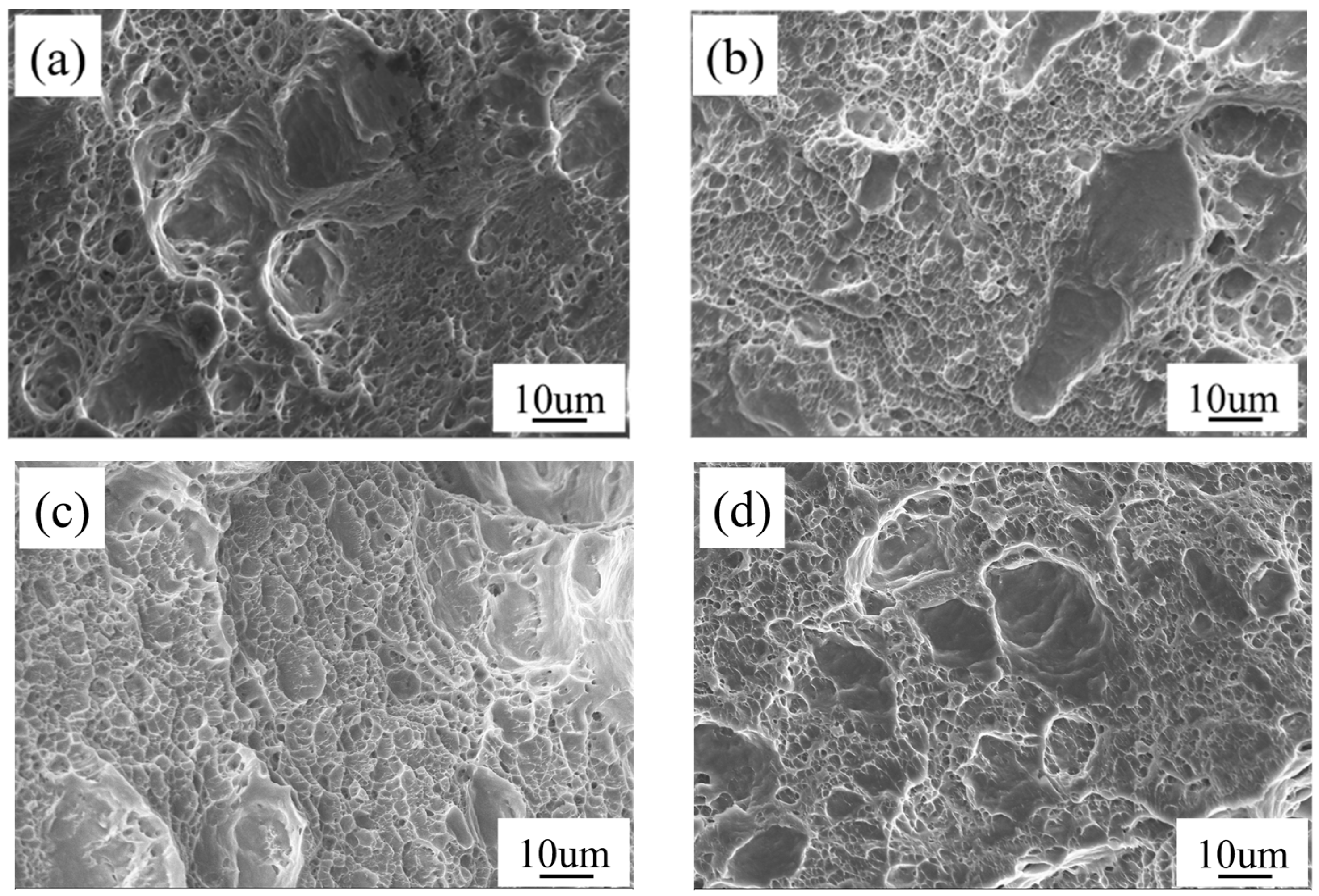
3.4. Mechanical Property

Figure 11 shows the tensile properties of the Al-Mg-Si-Cu alloy at different welding speeds. With increasing welding speed, the tensile strength and elongation are shown to first increase and then decrease because the welding speed and the peak temperature of the welded joint are inversely proportional. When the welding speed is low, the peak temperature is high, grain growth occurs and the impurity phase will gather; when the welding speed is too fast, the peak temperature is low, the material mobility is poor and hole-type defects will occur. Therefore, at a welding speed of 125 mm/min, the joint has the best overall performance, with a tensile strength and elongation of 200.7 MPa and 12.7%, respectively.
Figure 12 shows the tensile fracture morphology of joints at different welding speeds. As seen from the figure below, there are a large number of small dimples on the tensile fracture surface after FSW, so it can be determined that the fracture form is a ductile fracture. At the lower right of Figure 12a, it can be clearly observed that the distribution of dimples is relatively small and shallow. In the middle of Figure 12a, there are also pits with precipitated phases as the core, so their toughness is poor. Figure 12b shows the most uniform distribution of dimples, but there are parabolic pits, which may be formed by second-phase particles under tensile stress. In Figure 12c, in addition to the dimples, there are also unevenly distributed tear edges. Figure 12d is similar to Figure 12b in that there are parabolic holes.

4. Conclusions

(1)
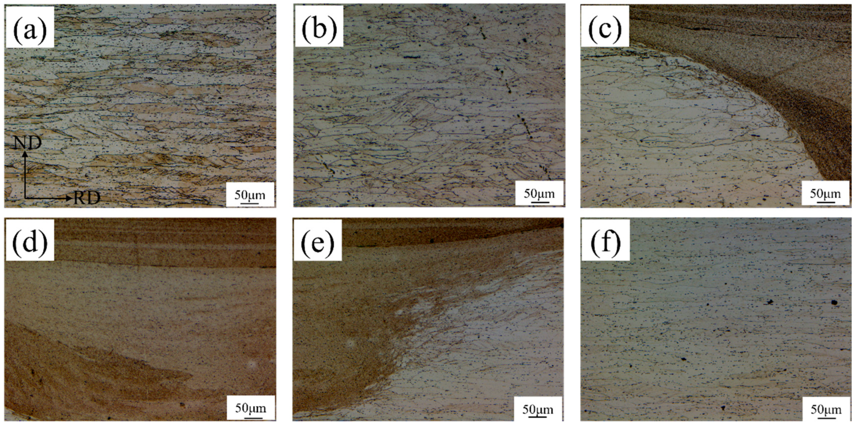
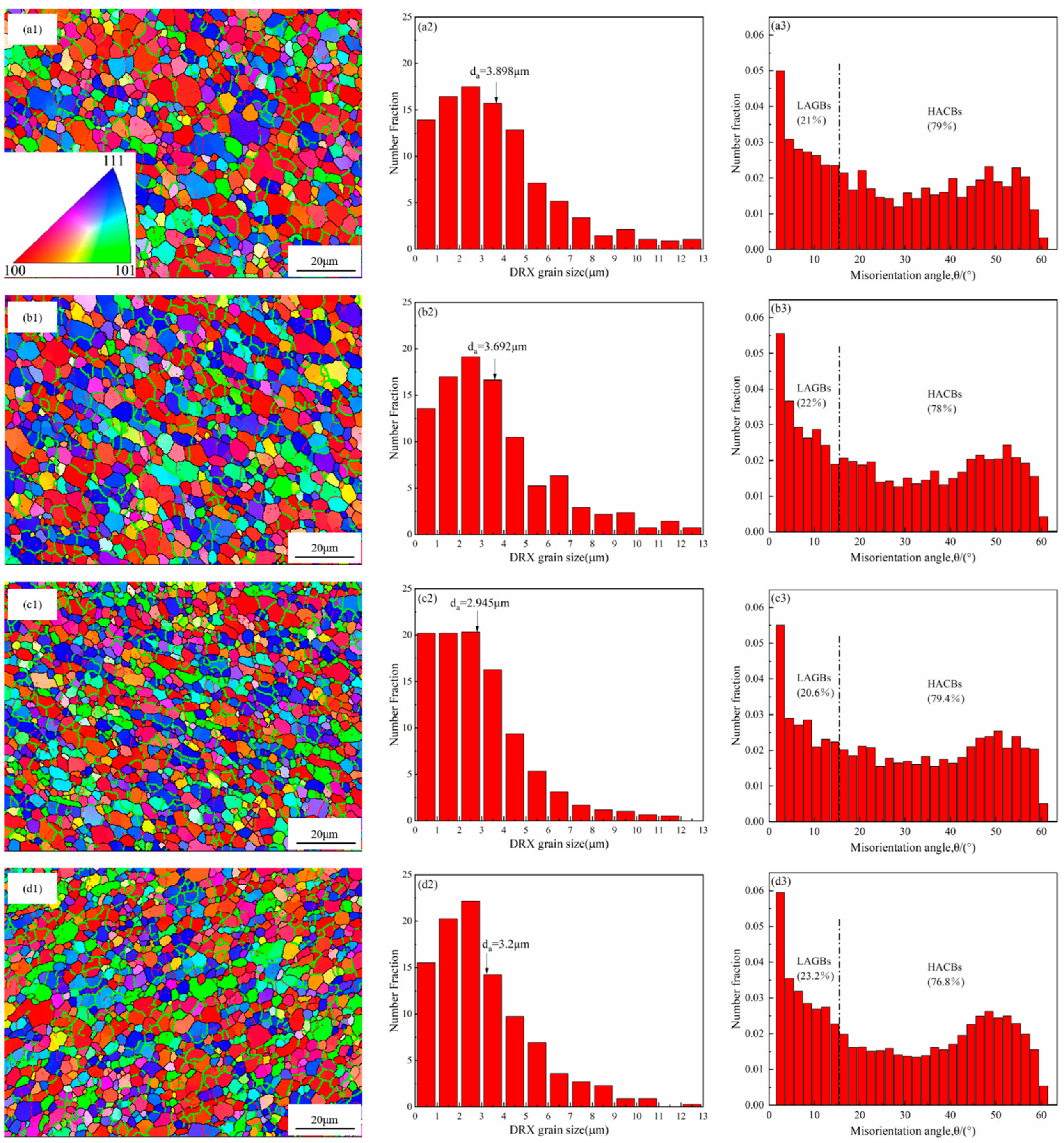
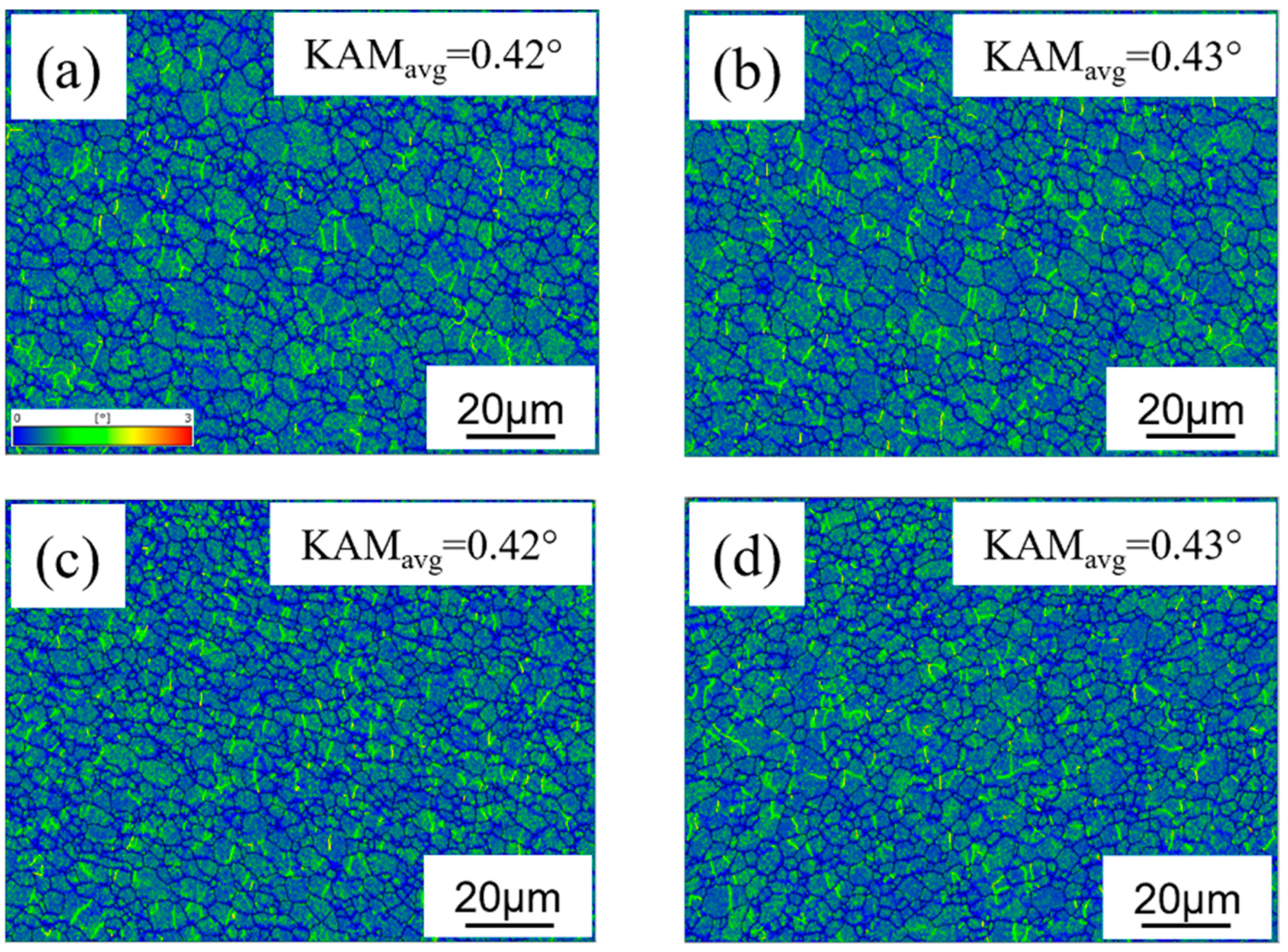
During the FSW welding process, the organisation in the HZ underwent thermomechanical coupling, dynamic recrystallisation occurred, fine equiaxed crystals formed and large angular grain boundaries accounted for more than 75% of all the grains. At a welding speed of 125 mm/min, the average grain size is the smallest, 2.945 μm. With an increase in welding speed, the GND density increases;
(2)
When the welding speed is between 75 mm/min and 150 mm/min, the main textures in the NZ are (111)(1 1 0) and (111)( 1 10 ) shear textures, (001)(110) recrystallisation texture, and (110) silk texture. As the welding speed decreases, the (111)(1 1 0) texture will first increase and then decrease;
(3)
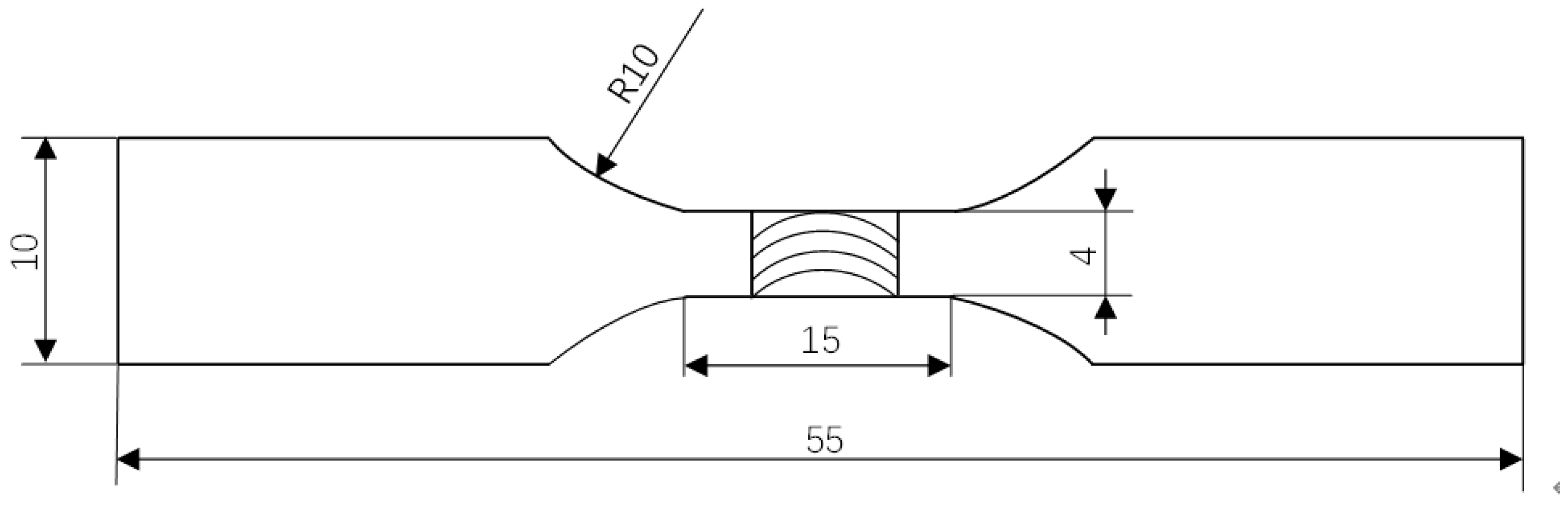
As the welding speed increases, the tensile strength and elongation of Al-Mg-Si-Cu alloy welded joints show a pattern of increasing and then decreasing. The joint performance is optimal at 125 mm/min, with a tensile strength and elongation of 200.7 MPa and 12.7%, respectively. Fracture of the Al-Mg-Si-Cu alloy joints occurs in the form of ductile fractures.

Author Contributions

Conceptualization, Z.L. and Y.S.; Methodology, Z.L., W.L. and J.H.; Formal analysis, G.L. and H.L.; Data curation, J.H., G.L. and H.L.; Writing—original draft, Z.L.; Funding acquisition, Y.S. and W.L. All authors have read and agreed to the published version of the manuscript.

Funding

Supported by the Guangxi Science and Technology Project (Grant No. AD22080042) and the 2022 Project of Scientific Research Basic Ability Improvement for Young and Middle-aged Teachers in Guangxi Universities (Grant No. 2022ky0351).

Data Availability Statement

The data that support the findings of this study are available from the corresponding author upon reasonable request.

Conflicts of Interest

The authors declare no conflict of interest.

References

  1. Zhou, X. Study on Large Strain Rolling and Mechanical Behavior of AlMgSiCu Alloy; Guangxi University of Science and Technology: Liuzhou, China, 2017. [Google Scholar]
  2. Sun, J.; Zhu, H.; Yu, H.; Guan, P.; Sun, L. Relationship Between Microstructure Defects and Process Parameters of Aluminum Alloy Friction Stir Welded Joint. Hot Work Technol. 2018, 47, 45–47, 52. [Google Scholar]
  3. Zhang, L.; Lin, N.; Zou, J.; Xie, R. Research Status on Friction Stir Welding of Aluminum Alloy. Hot Work Technol. 2020, 49, 1–6. [Google Scholar]
  4. Yi, T.; Liu, S.D.; Fang, C.; Jiang, G.D. Role of oxides in the formation of hole defects in friction stir welded joint of 2519-T87 aluminum alloy. J. Cent. South Univ. 2022, 29, 3836–3846. [Google Scholar] [CrossRef]
  5. Ming, W.; Sun, P.; Zhang, Z.; Qiu, W.; Du, J.; Li, X.; Guo, X. A systematic review of machine learning methods applied to fuel cells in performance evaluation, durability prediction, and application monitoring. Int. J. Hydrog. Energy 2023, 48, 5197–5228. [Google Scholar] [CrossRef]
  6. Jing, H.; Feng, Q.; Xu, L.; Zhao, L.; Han, Y. Microstructure and Mechanical Properties of Friction Stir Welds on 6063-T6 Aluminum Alloy. J. Mech. Eng. 2020, 56, 13–19. [Google Scholar]
  7. Jin, Y.; Huo, R.; Li, C.; Wang, X. Influence of rotational speed on fracture characteristics of 7055 aluminum alloy friction stir welded joints. Trans. China Weld. Inst. 2017, 38, 10–13, 18. [Google Scholar]
  8. Dong, P.; Li, H.; Sun, D.; Gong, W.; Liu, J. Effects of welding speed on the microstructure and hardness in friction stir welding joints of 6005A-T6 aluminum alloy. Mater. Des. 2013, 45, 524–531. [Google Scholar] [CrossRef]
  9. Ding, T.; Yan, H.G.; Chen, J.H.; Xia, W.J.; Bin, S.U. Effect of welding speed on microstructure and mechanical properties of Al−Mg−Mn−Zr−Tialloy sheet during friction stir welding. Trans. Nonferrous Met. Soc. China 2021, 31, 3626–3642. [Google Scholar] [CrossRef]
  10. Yuan, G.C.; Liang, C.L.; Liu, H.; Yuan, Q. Crystal orientation in nugget zone of friction stir welded 5083 aluminum alloy plates. Trans. Nonferrous Met. Soc. China 2014, 35, 79–82. [Google Scholar]
  11. Zhang, L.; Wang, X.; Wei, X.; Liu, X.; Chai, T. Effect of rotation speed on texture type in friction stir welding joint for 6082-T6 aluminum alloy. Trans. Nonferrous Met. Soc. China 2019, 40, 128–132. [Google Scholar]
  12. Shi, L.; Dai, X.; Tian, C.; Wu, C. Microstructure and mechanical properties of 2195-T6 Al-Li alloy joint prepared by friction stir welding. Trans. Nonferrous Met. Soc. China 2022, 43, 25–34. [Google Scholar]
  13. Liu, H.; Hu, Y.; Dou, C.; Sekulic, D.P. An effect of the rotation speed on microstructure and mechanical properties of the friction stir welded 2060-T8 Al-Li alloy. Mater. Charact. 2017, 123, 9–19. [Google Scholar] [CrossRef]
  14. Yang, H.; Zhao, H.; Xu, X.; Sun, G.; Zhou, L.; Zhao, H.; Liu, H. Microstructure and Properties of 2A14-T4 Aluminum Alloy T Joint by SSFSW. Mater. Rep. 2021, 35, 20045–20051. [Google Scholar]
  15. Humphreys, F.J.; Hatherly, M. Recrystallization and Related Annealing Phenomena, 2nd ed.; Elsevier: Amsterdam, The Netherlands, 2012; pp. 333–378. [Google Scholar] [CrossRef]
  16. Li, Y.; Yan, H.; Chen, J.; Xia, W.; Su, B.; Ding, T.; Li, X. Influences of welding speed on microstructure and mechanical properties of friction stir welded Al–Mg alloy with high Mg content. Mater. Res. Express 2020, 7, 76506. [Google Scholar] [CrossRef]
  17. Su, J.Q.; Nelson, T.W.; Mishra, R.; Mahoney, M. Microstructural investigation of friction stir welded 7050-T651 aluminium. Acta Mater. 2003, 51, 713–729. [Google Scholar] [CrossRef]
  18. Li, L.; Zhang, P.; Yi, L.; Wu, S.; Zhou, Q. Effect of Welding Speed on Properties of Friction Stir Welded Joint of Aluminum Alloy. J. Hunan Univ. Nat. Sci. 2021, 48, 120–128. [Google Scholar]
  19. Cha, J.W.; Jin, S.; Park, S.H. Influence of Ca addition on microstructural characteristics and mechanical properties of Mg–5Bi–3Al alloy extruded at extremely high speed. Mater. Sci. Eng. A 2023, 862, 144490. [Google Scholar] [CrossRef]
  20. Calcagnotto, M.; Ponge, D.; Demir, E.; Raabe, D. Orientation gradients and geometrically necessary dislocations in ultrafine grained dual-phase steels studied by 2D and 3D EBSD. Mater. Sci. Eng. A 2010, 527, 2738–2746. [Google Scholar] [CrossRef]
  21. Srivastava, V.C.; Schneider, A.; Uhlenwinkel, V.; Ojha, S.N.; Bauckhage, K. Age-hardening characteristics of Cu–2.4 Ni–0.6 Si alloy produced by the spray forming process. J. Mater. Process. Technol. 2004, 147, 174–180. [Google Scholar] [CrossRef]
  22. Kubin, L.P.; Mortensen, A. Geometrically necessary dislocations and strain-gradient plasticity: A few critical issues. Scr. Mater. 2003, 48, 119–125. [Google Scholar] [CrossRef] [Green Version]
  23. Yan, Z.; Wang, D.; He, X.; Wang, W.; Zhang, H.; Dong, P.; Sun, L. Deformation behaviors and cyclic strength assessment of AZ31B magnesium alloy based on steady ratcheting effect. Mater. Sci. Eng. A 2018, 723, 212–220. [Google Scholar] [CrossRef]
  24. Xie, S.; Sun, Y.; He, J.; Zhu, J.; Fang, D. Effect of cryogenic rolling on microstructure and mechanical properties of 2524 aluminum alloy. Trans. Mater. Heat Treat. 2022, 43, 58–65. [Google Scholar]
  25. Ql, J.; Gong, Z.; Kang, K.; Jin, Z. Effect of Rolling Processes on Texture Evolution in High-strength 7150 Aluminum Alloy Plate. Shanghai Met. 2019, 41, 59–65. [Google Scholar]
  26. Haase, C.; Barrales-Mora, L.A. Influence of deformation and annealing twinning on the microstructure and texture evolution of face-centered cubic high-entropy alloys. Acta Mater. 2018, 150, 88–103. [Google Scholar] [CrossRef] [Green Version]
  27. Nezakat, M.; Akhiani, H.; Sabet, S.M.; Szpunar, J. Electron backscatter and X-ray diffraction studies on the deformation and annealing textures of austenitic stainless steel 310S. Mater. Charact. 2017, 123, 115–127. [Google Scholar] [CrossRef]
  28. Jamaati, R.; Toroghinejad, M.R. Effect of stacking fault energy on deformation texture development of nanostructured materials produced by the ARB process. Mater. Sci. Eng. A 2014, 598, 263–276. [Google Scholar] [CrossRef]
  29. Yang, Y.; Zhang, Q.; Tian, Q. Mechanical Properties and Texture Evolution Characteristics of 5052 Al Alloy under Large Deformation. Hot Work. Technol. 2022, 51, 74–78. [Google Scholar]
  30. Engler, O.; Hirsch, J. Control of recrystallisation texture and texture-related properties in industrial production of aluminium sheet. Int. J. Mater. Res. 2009, 100, 564–575. [Google Scholar] [CrossRef]
  31. Ghosh, A.; Ghosh, M. Microstructure and texture development of 7075 alloy during homogenisation. Philos. Mag. 2018, 98, 1470–1490. [Google Scholar] [CrossRef]
  32. Ghosh, A.; Roy, A.; Ghosh, A.; Ghosh, M. Influence of temperature on microstructure, crystallographic texture and mechanical properties of EN AW 6016 alloy during plane strain compression. Mater. Today Commun. 2021, 26, 101808. [Google Scholar] [CrossRef]
  33. Ghosh, A.; Ghosh, M.; Seikh, A.H.; Alharthi, N.H. Phase transformation and dispersoid evolution for Al-Zn-Mg-Cu alloy containing Sn during homogenisation. J. Mater. Res. Technol. 2020, 9, 1–12. [Google Scholar] [CrossRef]
  34. Ghosh, A.; Ghosh, M.; Kalsar, R. Influence of homogenisation time on evolution of eutectic phases, dispersoid behaviour and crystallographic texture for Al–Zn–Mg–Cu–Ag alloy. J. Alloys Compd. 2019, 802, 276–289. [Google Scholar] [CrossRef]
  35. Madhavan, R.; Ray, R.K.; Suwas, S. Texture transition in cold-rolled nickel–40 wt.% cobalt alloy. Acta Mater. 2014, 74, 151–164. [Google Scholar] [CrossRef]
  36. Zhang, C.; Huang, G.; Liu, Q. Quantitative analysis of grain structure and texture evolution of dissimilar AA2024/7075 joints manufactured by friction stir welding. Mater. Today Commun. 2021, 26, 101920. [Google Scholar] [CrossRef]
  37. Mao, W.M. Crystallographic Texture and Anisotropy of Metallic Materials; Science Press China: Beijing, China, 2002. [Google Scholar]
  38. Zhang, L.; Wang, X.; Liu, X. Effect of Dynamic Recrystallization Mode on Texture Type for the Friction-Stir-Welded 6082-T6 Aluminum Alloy. Mater. Rep. 2019, 33, 665–669. [Google Scholar]
  39. Zhang, L. Microstructure Evolution of 6082-T6 Aluminum Alloy in Friction Stir Welding Process and Its Influence on Mechanical Properties of Welded Joints; Lanzhou University of Technology: Lanzhou, China, 2018. [Google Scholar]
  40. Fonda, R.W.; Bingert, J.F. Texture variations in an aluminum friction stir weld. Scr. Mater. 2007, 57, 1052–1055. [Google Scholar] [CrossRef]
Figure 1. Dimensions of the tensile sample.
Metals 13 01120 g001
Figure 2. Microstructure of each region of the FSW. (a) BM; (b) AS-HAZ; (c) AS-TMAZ; (d) NZ; (e) RS-TMAZ; (f) TS-HAZ.
Metals 13 01120 g002
Figure 3. EBSD maps, grain size distribution and misorientation angle distribution of the NZ at different welding speeds. (a1a3) 75 mm/min; (b1b3) 100 mm/min; (c1c3) 125 mm/min; (d1d3) 150 mm/min.
Metals 13 01120 g003
Figure 4. Distribution of the kernel average misorientation in the NZ at different welding speeds. (a) 75 mm/min; (b) 100 mm/min; (c) 125 mm/min; (d) 150 mm/min.
Metals 13 01120 g004
Figure 5. Histogram of the probability of geometric necessary dislocation density in the NZ at different welding speeds. (a) 75 mm/min; (b) 100 mm/min; (c) 125 mm/min; (d) 150 mm/min.
Metals 13 01120 g005
Figure 6. The (001), (110) and (111) pole figures showing the texture of the BM.
Metals 13 01120 g006
Figure 7. The ODF figures of the BM.
Metals 13 01120 g007
Figure 8. The (001), (110) and (111) pole figures of the NZs at different welding speeds. (a) 75 mm/min; (b) 100 mm/min; (c) 125 mm/min; (d) 150 mm/min.
Metals 13 01120 g008
Figure 9. The ODF diagram of the welding core zone at different welding speeds. (a) 75 mm/min; (b) 100 mm/min; (c) 125 mm/min; (d) 150 mm/min.
Metals 13 01120 g009
Figure 10. Grain distribution of various textures. (a) 75 mm/min; (b) 100 mm/min; (c) 125 mm/min; (d) 150 mm/min.
Metals 13 01120 g010
Figure 11. Tensile properties of joints at different welding speeds.
Metals 13 01120 g011
Figure 12. Tensile fracture morphology of the samples at different welding speeds. (a) 75 mm/min; (b) 100 mm/min; (c) 125 mm/min; (d) 150 mm/min.
Metals 13 01120 g012
Table 1. Welding parameters for the FSW.
Rotational Speed/r·min−1Welding Speed/mm·min−1
75075
750100
750125
750150
Table 2. Volume fraction of the texture components of NZs at different welding speeds.
Colour CodeOrientation
(h k l)(u v w)
75 mm/min100 mm/min125 mm/min150 mm/min
Metals 13 01120 i001(0 0 1)(1 1 0)16.926.620.626.9
Metals 13 01120 i002(1 1 1)(1 1 0)18.131.119.2Metals 13 01120 i004
Metals 13 01120 i003(1 1 1)( 1 1 0) Metals 13 01120 i004Metals 13 01120 i004Metals 13 01120 i00422.3
Disclaimer/Publisher’s Note: The statements, opinions and data contained in all publications are solely those of the individual author(s) and contributor(s) and not of MDPI and/or the editor(s). MDPI and/or the editor(s) disclaim responsibility for any injury to people or property resulting from any ideas, methods, instructions or products referred to in the content.

