Article

Mechanism of Microstructural Alterations of M50 Bearing Steel during Rolling Contact Fatigue under High Loads

1
Collaborative Innovation Center of Steel Technology, University of Science and Technology Beijing, Beijing 100083, China
2
Research Institute of Special Steels, Central Iron & Steel Research Institute Company Limited, Beijing 100081, China
*
Author to whom correspondence should be addressed.
Metals 2023, 13(4), 769; https://doi.org/10.3390/met13040769
Submission received: 20 March 2023 / Revised: 7 April 2023 / Accepted: 10 April 2023 / Published: 14 April 2023
(This article belongs to the Special Issue Fracture Mechanics of Metals)

Abstract

:
Rolling contact fatigue (RCF) of vacuum induction melted–vacuum arc remelted (VIM-VAR) M50 bearing steel under high loads was carried out, using a three-ball-rod RCF tester. Dark etching regions (DER) and butterflies were found in the subsurface region below the raceway of the RCF-tested sample. The DER appeared in the region of maximum shear stress located at a depth of 30 μm to 170 μm below the raceway. Carbon atoms migrated through high-density dislocations, and part of the martensite plates was transformed into cellular ferrites, due to the redistribution of dislocations during the deformation of martensite under the action of cyclic shear stress. Butterflies appeared in the region of maximum shear stress located at a depth of 20 μm to 314 μm below the raceway. Butterflies were initiated in the primary carbides, with length values ranging from 5 μm to 15 μm. The plate martensite in the butterfly wings was transformed into nanocrystalline ferrites, due to the increase in the dislocation density and rearrangement of dislocations during the extension of fatigue cracks from the primary carbides to the matrix under cyclic shear stress.

1. Introduction

The fatigue failure models for bearings include surface originated spalling and subsurface originated spalling. When bearings operate under the designed loading and lubrication, subsurface-originated spalling becomes the decisive factor in determining the life of the bearing. It is well known that microstructure alterations in bearing steel occur under long-term cyclic loading. It is commonly thought that this microstructural alteration is closely related to the subsurface-originated spalling. A dark etching region (DER) and white etching area (WEA) were found below the raceway of a bearing sample [1]. The DER was formed by the decomposition of martensite, but the distribution of the DER was not homogeneous. Most of the WEAs were butterfly structures associated with inclusions. Although researchers have conducted many investigations on the microstructural alteration in rolling contact fatigue (RCF), the conditions of microstructural alteration and the mechanism of microstructural alteration are still not fully understood.
The structure, formation mechanism, and influencing factors of DER in SAE 52,100 bearing steel have been studied extensively. Swahn et al. [2] found that part of the martensite decay occurs through the formation of ferrite in the DER of bearing steel. The fragmentation and dissolution of cementite carbides results in a redistribution of carbon during martensite decay in DER [3]. However, the carbon content in ferrite is lower than in martensite. Therefore, a wide carbon distribution during martensite decay under rolling contact fatigue is a problem. The redistribution of carbon is necessary during martensitic decay. Österlund et al. [4] found that disc-shaped carbide was produced during the martensitic decay of SAE 52,100 bearing steel. The formation of disc-shaped carbides caused a wide diffusion of carbon from ferrite to carbides in the DER. Fu et al. [5] found that the carbon content of ferrite in DER was much lower than that of the original martensite, using an atom probe tomography (APT). The formation of the DER was affected by the redistribution of carbon. Kang et al. [6] proposed that dislocation assists carbon migration during DER formation. Kang et al. [7] proposed that the main cause of DER formation in 0.57C-bearing steel is the carbon migration and recrystallization caused by cumulative plastic deformation. At higher applied loads and longer revolutions, 30° white etching bands (WEBs) and 80° white etching bands were found in DER [2,8]. Šmeļova et al. [9] proposed that the globular ferrite grains and elongated ferrite grains in 30° WEBs and 80° WEBs are formed by recrystallization of martensite during the earliest stages of the microstructure alteration in DER. Fu et al. [10] found that the formation of WEBs is controlled by the principle shear stress under the raceway. El Laithy et al. [11] found that the nucleation and growth of 80° WEBs depended on the density of the 30° WEBs under two different contact pressures of 2.9 GPa and 3.5 GPa. Abdullah et al. [12] found that a 160 °C temperature was favorable for the formation of WEBs under 6 GPa. The formation of WEBs can be explained by the rearrangement of dislocations and the redistribution of carbon. The formation of lenticular carbides in 80° WEBs is enhanced at elevated temperature under 6 GPa [13]. El Laithy et al. [14] proposed that the formation of equiaxed ferrite grains in both 30° WEBs and 80° WEBs was the result of recrystallization, but elongated grains were formed in recovery form under 2.9 GPa and 3.5 GPa. No DER was found under the raceway of an M50 bearing steel sample under rolling contact fatigue [15,16]. No disc-shaped carbides or WEBs were found in DER of the M50 bearing steel specimens [17]. Research on DER has mainly focused on 52,100 bearing steel, while research on M50 high temperature bearing steel is relatively scarce.
WEAs are sometimes observed in the cross-section parallel to the raceway after a long period of cyclic loading. WEAs are related to butterflies and white etching cracks (WECs). Butterflies with a wing-like structure usually originate from inclusions and microscopic cracks. Loy et al. [18] found that WEAs under the wear raceway originated from the second-phase particles under rolling contact fatigue of En31 bearing steel. WEAs are often associated with fatigue cracks, which can lead to spalling when the fatigue cracks extend to the surface under shear stress. Becker et al. [19] found that a butterfly wing consisted of ultrafine ferrite grains (10 nm) using TEM. Grabulov et al. [20] concluded that carbides dissolved in the butterfly of an SAE 52,100 bearing steel specimen and proposed that the formation mechanism of ultrafine ferrite grains was recrystallization. Recrystallization occurs in butterflies as a result of the stabilization of the crystal defects by the dissolved carbon [21]. It is controversial whether the initiation of cracks precedes the transformation of microstructure during the formation of butterflies. Hashimoto et al. [22] found that cracks initiated from inclusions on the subsurface of raceway, but no butterflies were found at these inclusions. Evans et al. [23] found cavities in the matrix adjacent to the crack and at the crack tip of butterflies and proposed a cavity coalescence mechanism for the nucleation of butterfly cracks. WECs are one of the main failure models of wind turbine gearbox bearings [24,25]. WECs can be formed by connection between cracks initiated at subsurface inclusions or butterfly cracks [26,27,28]. WECs can be initiated not only at the subsurface but also at the surface [29]. The density of WECs increases with the increase of fatigue load and fatigue life [30]. Microstructural alterations occur in the white etching areas associated with white etching cracks (WEAs/WECs). Oezel et al. [31] found that carbide dissolution and the formation of nanocrystalline ferrite grains occurred within WEAs/WECs. C segregation was found at the ferrite grain boundaries, using APT to characterize the WEAs/WECs [32,33]. Kadin et al. [34] proposed that the formation mechanism of WECs is the local microstructural alterations caused by crack face rubbing. Morsdorf et al. [35] proposed that cracks not only move in the direction of crack propagation, but also in the direction perpendicular to the crack propagation, which provided a new theory for crack distribution in WEAs. Spille et al. [36] found pores associated with a transformed microstructure in the subsurface, which would promote the formation of WECs at a later stage. Dogahe et al. [37] found nanosized pores in the subsurface, which significantly reduced the number of cycles in bearing application, causing a significantly earlier transition from microstructural short cracks to long crack propagation. Holweger et al. [38] found that the combination of electrical charging–discharging and the presence of chemicals, represented by additives, lead to the formation of cracks and WEA. Steinweg et al. [39] proposed that the formation of nanocrystalline structures can be attributed to high local plastic deformation, and that the electrical current introduced contributes to the local plasticity required for WEA/WEC formation.
Vacuum induction melted–vacuum arc remelted (VIM-VAR) M50 bearing steel is a widely used high-temperature bearing steel. VIM-VAR M50 bearing steel contains a large amount of undissolved primary carbides (MC and M2C) after austenitizing heat treatment [40]. It was found that the matrix martensite of VIM-VAR M50 bearing steel contains a large amount of secondary carbides (M2C, M4C, and M3C) using APT and TEM [41]. Ganti et al. [42] found that butterflies were initiated at inclusions in VIM-VAR AISI M50 steel. Guetard et al. [43] found that all butterflies originated from primary carbides, from the statistical distribution of butterflies in VIM-VAR M50 steel. The density of butterflies increased with the increase in the number of cycles and contact stress [44].
Most of the previous studies on microstructural alterations in bearing steels during rolling contact focused on AISI 52,100 bearing steel. The composition of AISI 52,100 bearing steel contains higher concentrations of C and Cr. AISI 52,100 bearing steel consists of plate martensite, residual austenite, primary carbides (Fe, Cr)3C, and one or more of ε-phase, η-phase, and θ-phase [45]. It has been proposed that the formation of DER in AISI 52,100 bearing steel is due to the formation of fine ferrite grains and the migration of C from partial martensite to high-density dislocations and carbides [5,6]. It has been proposed that globular ferrite grains and elongated ferrite grains are formed by recrystallization or dynamic recrystallization in the early stages of DER formation [46]. However, there is still controversy about the mechanism of the formation of globular ferrite grains and elongated ferrite grains in DER. It was found that the WEB in AISI 52,100 bearing steel consists of equiaxed grains, elongated grains, and lenticular carbides. The proposed cyclic shear stress caused primary carbide dissolution and the deformation of the supersaturated ferrite, resulting in carbon migration, to form lenticular carbides [12]. El Laithy et al. [14] proposed that the formation of equiaxed ferrite in WEBs is due to the recrystallization caused by energy accumulation in the initial microstructure, and that elongated ferrite grains are formed by a grain rotation/coalescence recovery mechanism. However, no white etched bands were found in M50 bearing steel under rolling contact fatigue [42]. The butterflies in typical AISI 52,100 bearing steel originate at non-metallic inclusions; however, butterflies in M50 bearing steel originate at primary carbides. It was found that M3C carbides were dissolved during the formation of WEA in AISI 52,100 bearing steel under rolling contact fatigue [33]. M50 bearing steel contains a large amount of Mo, Cr, and V compared with AISI 52,100 bearing steel. M50 bearing steel contains a large amount of Mo-rich M2C carbides and V-rich MC carbides after heat treatment. The effect of the primary and secondary carbides in M50 bearing steel on butterfly formation is not clear. The mechanism of formation of DER and WEA in M50 bearing steel is not fully understood.
A ball-rod rolling contact fatigue tester was used to study the microstructure transformation of M50 bearing steel. The shape of the raceway on the specimen bar also facilitates the observation of the subsurface microstructure through the radial cross-sections. The influence of load and stress cycles on the DER and butterfly formation in M50 bearing steel was studied through multiple tests under different loads and different stress cycles. FIB was used to prepare TEM samples with near-surface area, DER, and butterfly, to further study the microstructure and formation mechanism of DER and butterfly in M50 bearing steel. In this paper, the effects of primary carbides, secondary carbides, and dislocation substructures on the microstructure alterations of M50 bearing steel during rolling contact fatigue were investigated.

2. Materials and Methods

VIM-VAR M50 bearing steel (Central Iron & Steel Research Institute Company Limited, Beijing, China) was used for RCF testing. The M50 bearing steel was austenitized at 1100 °C for 2 h, then quenched, tempered at 540 °C for 2 h, cold treated at −73 °C for 2 h, and then tempered twice at 540 °C. The M50 bearing steel after heat treatment was composed of tempered martensite, and very little austenite was retained. The hardness values of the test rod and steel balls were between 61 HRC and 62 HRC.
Fatigue tests were conducted on a ball-rod rolling contact fatigue tester (Central Iron & Steel Research Institute Company Limited, Beijing, China). The working principle of this rolling contact fatigue testing machine is shown in Figure 1. This testing machine contains a rotating cylindrical specimen (10 mm in diameter) and three radially loaded steel balls (12.7 mm in diameter). The three steel balls are separated through the cage at an angle of 120°. The surface roughness of the test rod and steel ball was 0.9 μm and 0.2 μm, respectively. Type 4050 lubricant (Sinopec Research Institute of Petroleum Processing Co., Ltd., Beijing, China) was used in this test. The base oil of lubricant 4050 is neopentyl polyol ester. The measured property data of lubricant 4050 are given in Table 1. The rotation speed of the test rod was 8000 rpm. The fatigue tests were stopped when a certain number of cycles, N, was reached. RCF specimens were tested at a maximum Hertzian contact stress P0 = 4 GPa for 1.37 × 10⁷ cycles, 2.33 × 10⁸ cycles, and 5.11 × 10⁸ cycles. RCF specimens were tested at a maximum Hertzian contact stress P0 = 5 GPa for 1.33 × 10⁷ cycles, 1.14 × 10⁸ cycles, 2.12 × 10⁸ cycles, and 5.65 × 10⁸ cycles.
Radial cross-sections, parallel to the raceway, were made through the center of the raceway of the rod. Radial cross-sections were made to a metallographic standard, followed by etching with a solution of 4% Nital for 1 min. The radial cross-sections were examined under an Olympus GX53 microscope (Olympus, Tokyo, Japan). The area below the raceway, with a length of 20.94 mm and a depth of 500 μm, was observed. Optical micrographs were used to obtain the characteristics of the butterflies. The length of the butterflies, the depth of the butterflies from the raceway, the size of the primary carbide associated with the butterflies, and the angle between the butterflies and the raceway were measured using Image-Pro-Plus (IPP) software (version 6.0, Media Cybernetics, Inc., Rockville, MD, USA). Butterflies were observed through SEM (FEI Quanta 650, FEI Company, Hillsboro, OR, USA), in order to study their formation mechanism. TEM (FEI Tecnai G2 F20, FEI Company, Hillsboro, OR, USA) specimens were prepared using a focused ion beam (FIB), in order to precisely observe a certain location of the microstructural below the raceway.

3. Results and Discussion

3.1. Subsurface Microstructure Alterations

Microstructural observation of the radial cross-section in the center of the raceway of the RCF-tested samples was conducted using an optical microscope. No DERs and butterflies were observed in the radial cross-section in the center of the raceway of the RCF-tested samples under 4 GPa and 5 GPa, after 1.37 × 10⁷ cycles and 1.33 × 10⁷ cycles, respectively. Figure 2a shows an optical micrograph of the radial cross-section in the center of the raceway of the RCF-tested sample under 5 GPa after 1.33 × 10⁷ cycles. DER located at a depth of 30 μm to 130 μm below the raceway was observed in the radial cross-section of the RCF-tested sample under 4 GPa after 2.33 × 10⁸ cycles. The distribution of DERs was similar in the radial cross-section of the RCF-tested samples under 4 GPa after 2.33 × 10⁸ cycles and 5.11 × 10⁸ cycles. DER located at a depth of 50 μm to 170 μm below the raceway was observed in the radial cross-section of the RCF-tested sample under 5 GPa after 1.14 × 10⁸ cycles, as shown in Figure 2b. The distribution of DERs was similar in the radial cross-section of the RCF-tested samples under 4 GPa after 1.14 × 10⁸ cycles, 2.12 × 10⁸ cycles, and 5.65 × 10⁸ cycles. The depth of the DER increased as the maximum contact stress was increased from 4 GPa to 5 GPa.
Figure 2c,d show the typical morphology of the butterflies. Butterflies with single or two wings were found to be initiated at the primary carbides. Butterflies were found to form not only in the DER but also outside of the DER, as shown in Figure 2b.
Figure 3 shows the characteristic parameters of the butterflies in the RCF-tested samples under 4 GPa. Butterflies located at a depth of 19 μm to 247 μm below the raceway were observed in the radial cross-section of the RCF-tested sample under 4 GPa after 2.33 × 10⁸ cycles and 5.11 × 10⁸ cycles, as shown in Figure 3a. The depth values of the butterflies from the surface mainly ranged from 50 μm to 200 μm. The number of butterflies in the sample after 5.11 × 10⁸ cycles was higher than the number of butterflies in the sample after 2.33 × 10⁸ cycles under 4 GPa. The number of butterflies increased significantly with the increase in the number of cycles. The length values of the butterflies of the RCF-tested samples ranged from 10 μm to 35 μm under 4 GPa after 2.33 × 10⁸ cycles, as shown in Figure 3b. The length values of the butterflies of the RCF-tested samples ranged from 10 μm to 50 μm under 4 GPa after 5.11 × 10⁸ cycles. The length of the butterflies of the RCF-tested samples increased as the number of cycles increased from 2.33 × 10⁸ cycles to 5.11 × 10⁸ cycles under 4 GPa. The length of the primary carbides associated with butterflies in the RCF-tested samples ranged from 5 μm to 15 μm under 4 GPa after 2.33 × 10⁸ cycles and 5.11 × 10⁸ cycles, as shown in Figure 3c. The inclination values between the butterfly and raceway in the RCF-tested samples ranged from 20° to 30° under 4 GPa after 2.33 × 10⁸ cycles and 5.11 × 10⁸ cycles, as shown in Figure 3d.
Figure 4 shows the characteristics of the butterflies in the RCF-tested samples under 5 GPa. Butterflies located at a depth of 20 μm to 314 μm below the raceway were observed in the radial cross-section of the RCF-tested sample under 5 GPa after 1.14 × 10⁸ cycles, 2.12 × 10⁸ cycles, and 5.65 × 10⁸ cycles, as shown in Figure 4a. The depth of the butterflies in the RCF test specimens mainly ranged from 50 μm to 250 μm under 5 GPa after 1.14 × 10⁸ cycles and 2.12 × 10⁸ cycles, as shown in Figure 4a. However, the depth of the butterflies of the RCF test specimens ranged mainly from 50 μm to 350 μm under 5 GPa after 5.65 × 10⁸ cycles. Butterflies could form in deeper areas as the number of cycles was increased. The number of butterflies increased significantly in the RCF-tested sample under 5 GPa after 5.65 × 10⁸ cycles. The length values of the butterflies of the RCF-tested samples ranged from 10 μm to 35 μm under 5 GPa after 1.14 × 10⁸ cycles and 2.12 × 10⁸ cycles, as shown in Figure 4b. The length of the primary carbides associated with butterflies in the RCF test samples ranged from 5 μm to 15 μm under 4 GPa after 1.14 × 10⁸ cycles, 2.12 × 10⁸ cycles and 5.65 × 10⁸ cycles, as shown in Figure 4c. The inclination values between the butterfly and raceway in the RCF test specimens ranged from 20° to 30°under 4 GPa after 1.14 × 10⁸, 2.12 × 10⁸ cycles, and 5.65 × 10⁸ cycles, as shown in Figure 4d.
When the maximum Hertzian stress P0 between the rod and the ball was 4 GPa, the maximum shear stress was 1.30 GPa at 107.45 μm below the raceway, and the maximum orthogonal shear stress was 0.94 GPa at 74.20 μm below the raceway. When the maximum Hertzian stress P0 between the rod and the ball was 5 GPa, the maximum shear stress was 1.63 GPa at 134.35 μm below the raceway and the maximum orthogonal shear stress was 1.20 GPa at 93.19 μm below the raceway. The DER and butterflies appeared in the region of maximum shear stress after a higher number of cycles, depending on the load. Butterflies could form at greater depths from the surface as the maximum contact stress increased. The increase in the number of cycles caused an increase in the number of butterflies, as well as an increase in the depth of the butterflies. There was a stress concentration at the primary carbide that caused the butterflies to form in areas other than where the DER appeared. The maximum contact stress, number of cycles, and primary carbide can have a significant effect on the formation and distribution of butterflies.

3.2. Near Surface Microstructure

In order to study the near surface microstructure after long-term cyclic loading, a TEM sample was prepared through FIB at 5 μm below the raceway of the RCF-tested sample under 5 GPa and after 2.12 × 10⁸ cycles, as shown in Figure 5a–d of the TEM micrographs of deformed plate martensite with a high density of dislocations. Figure 5c shows that the dislocation distribution in the martensitic plates was not uniform, and the dislocation density was very high in some regions. High-density dislocations were arrayed in the form of tangles. Martensitic plates were fragmented by dislocation tangles (DTs). It was found that not only the dislocation density changed, but also the dislocation substructure changed during cyclic loading. Martensitic plates were separated into irregular dislocation cells (DCs), as shown in Figure 5d. The boundary of the dislocation cell developed from the DTs. Figure 6a,b show TEM micrographs of twins in the martensitic plates with different dislocation densities. DTs were formed in the martensite plate with twins during long-term cyclic loading, as shown in Figure 6a. DCs were formed due to the interaction of the DTs and twin boundaries, as shown in Figure 6b. The increase in dislocation density under long-term cyclic loading led to changes in the dislocation substructure, due to the relatively low shear stress in the near surface region.

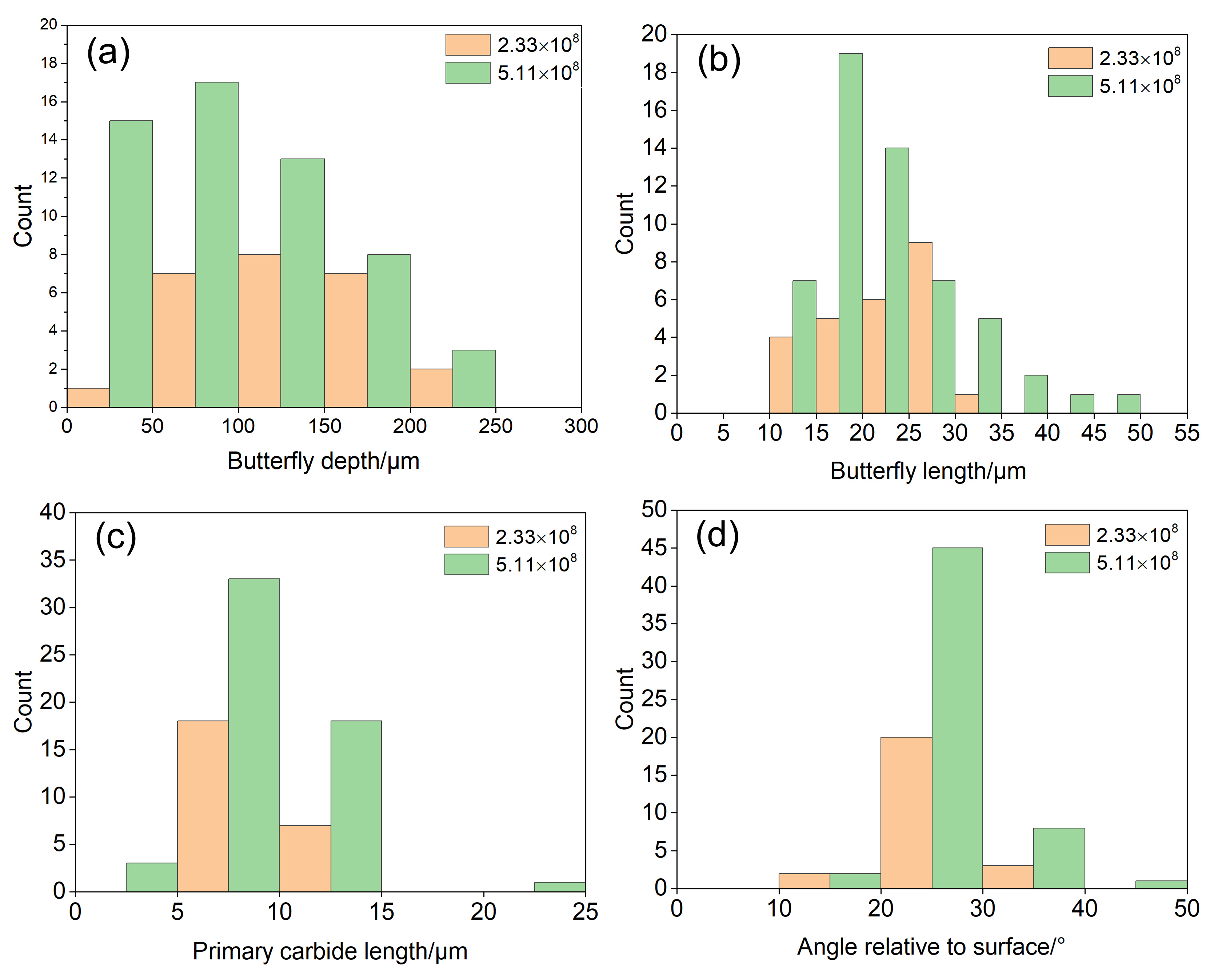
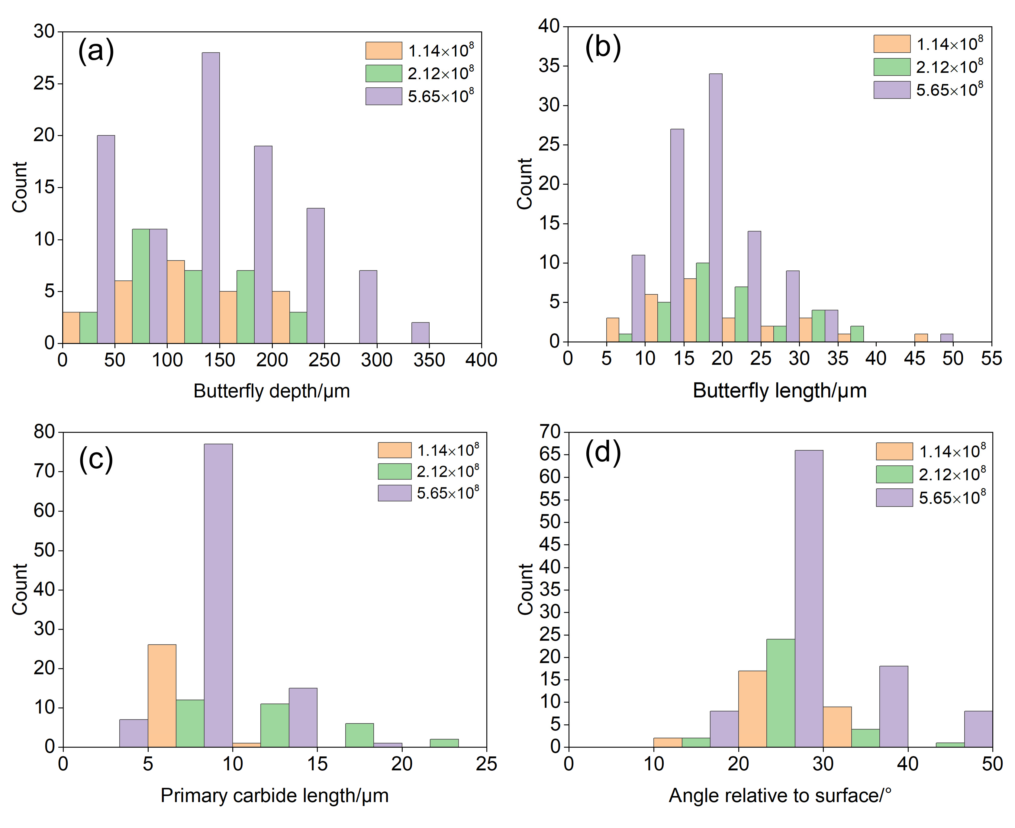
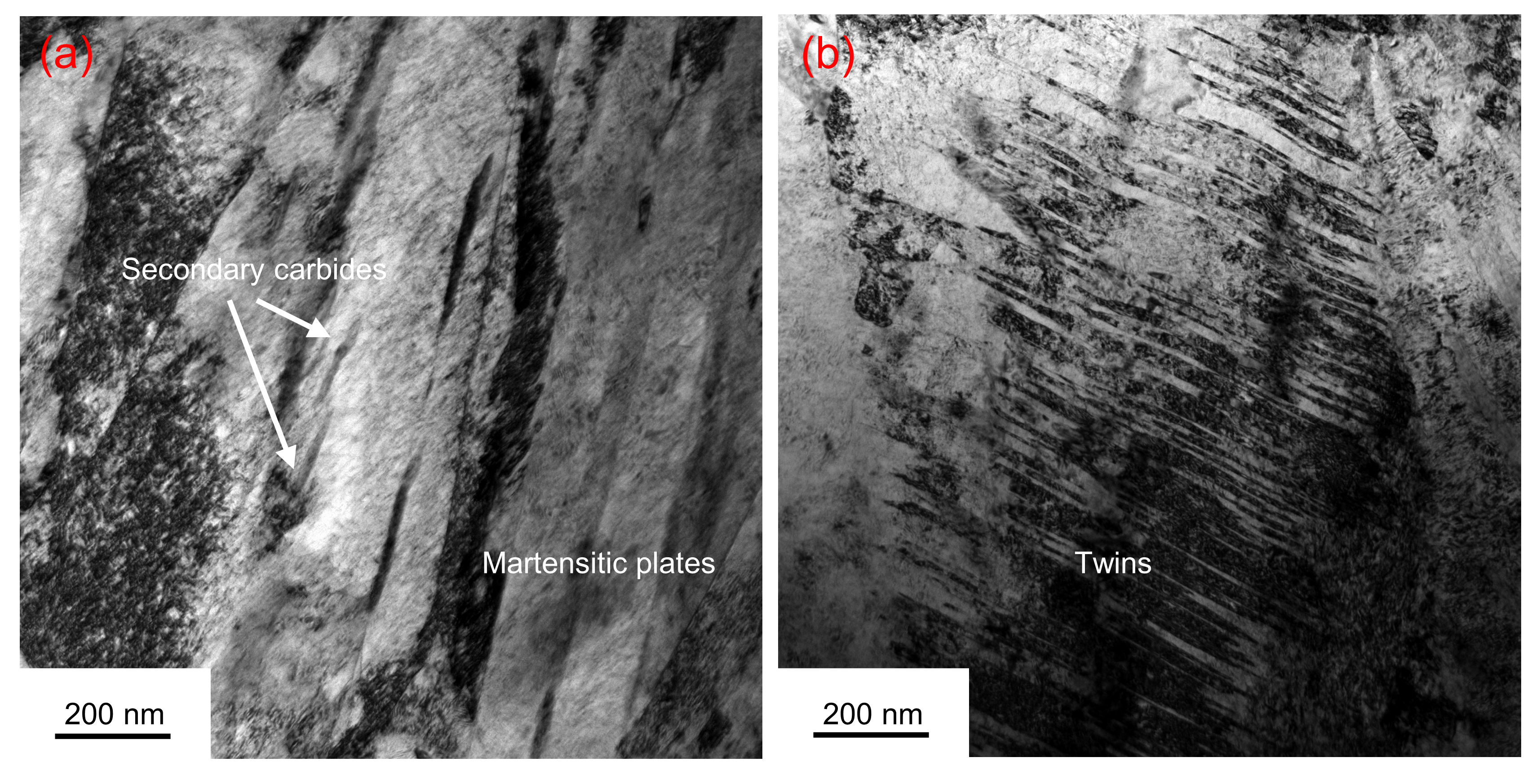
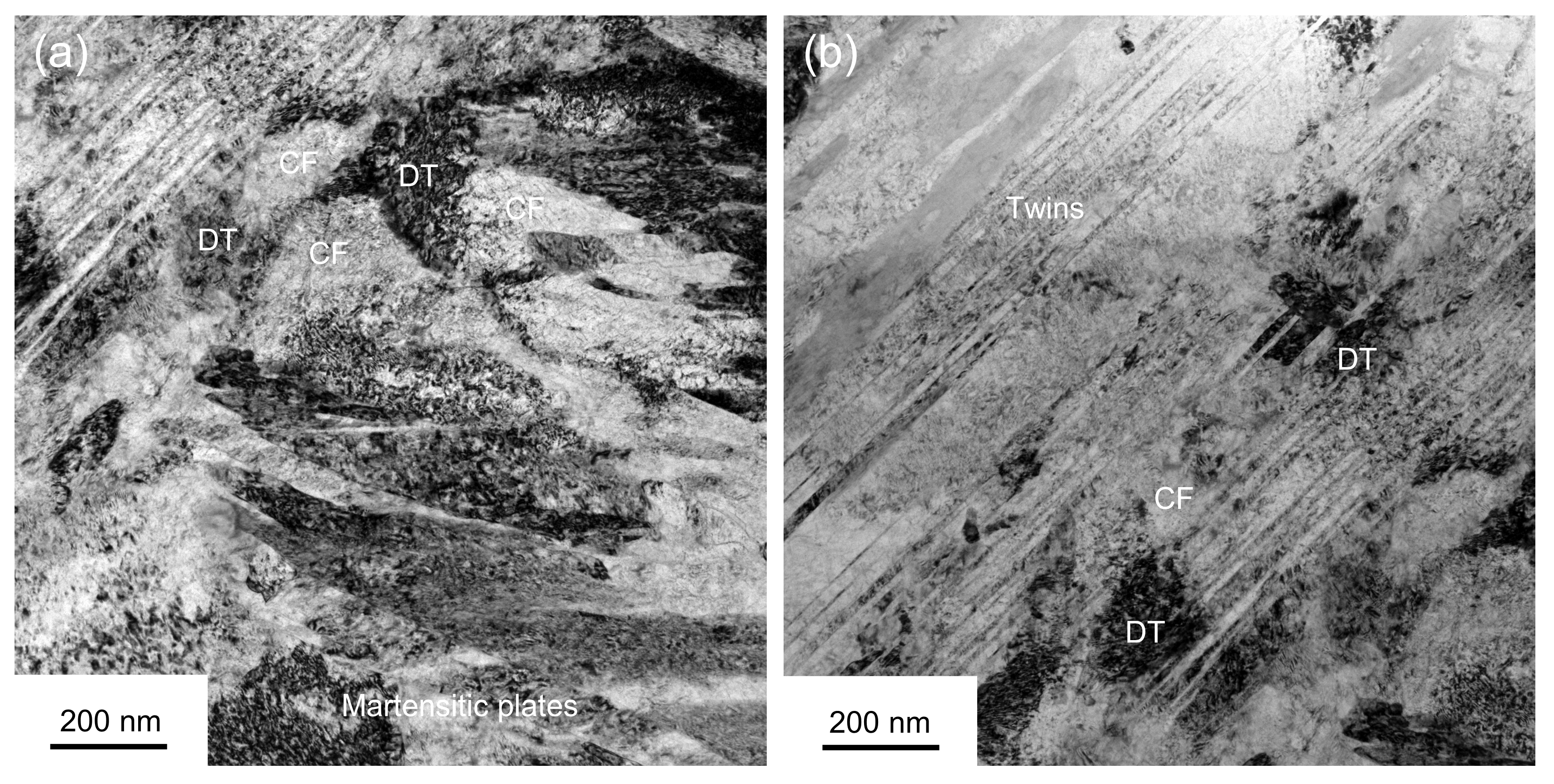
3.3. Microstructure of the DER and Butterfly

Figure 7a,b show TEM micrographs of the original M50 bearing steel with martensite. Figure 7a shows that the matrix of the M50 bearing steel is a plate martensitic with a higher density of dislocations. A large amount of nanoscale carbides precipitated in the martensite with carbon supersaturation during tempering. Figure 7b shows the TEM micrograph of plate martensite with twins. Figure 8a,b show the TEM micrographs of the DER located around the butterfly. Some martensite plates were transformed into cellular ferrites (CFs) in the DER under long-term cyclic loading, as shown in Figure 8a. First, the dislocation density increased under long-term cyclic shear stress and carbon atoms migrated through dislocations in the process of dislocation movement during deformation. Then, as the number of cycles increased, the martensite plates were fragmented by DTs into fine CFs. The dislocations in the DTs were rearranged and the boundaries of the CFs became more clear when the dislocation density reached a certain number. Some plate martensite with twins was also transformed into CFs in the DER under long-term cyclic loading, as shown in Figure 8b. The increase in dislocation density and the glide of dislocations led to a lot of DTs being generated within the twins under the action of cyclic shear stress. Twins were fragmented into DCs by the DTs. The accumulated plastic deformation led to a further increase in the density of dislocations with the increase in the number of cycles. Some twin boundaries disappeared during deformation, due to DTs and dislocation rearrangement. Some twins were also fragmented by DTs into CFs under long-term cyclic loading. The redistribution of carbon in the CFs was driven by the movement of carbon atoms assisted by dislocations. Carbon atoms could also be enriched at DTs. Some residual martensitic plates could still be found in the DER. The transformation of martensite in the DER was not uniform. Globular and elongated ferritic grains formed by dynamic recrystallization were are found in the DER of the AISI 52,100 bearing steel [46]. However, cellular ferrites formed by dislocation movement were found in DER of M50 bearing steel. Šmeļova et al. [9] found that small globular grains appeared preferentially in the chromium-depleted regions in the DER of AISI 52,100 bearing steel. The segregation of Cr may have delayed the formation of fine ferrite grains in the DER of AISI 52,100 bearing steel. The formation of cellular ferrite in the DER of M50 bearing steel was due to the high content of Cr, Mo, and V. The Cr, Mo, and V in the matrix of the M50 bearing steel had an obstructive effect on the movement of dislocations.
A butterfly formed at a depth of 55 μm below the raceway of the sample (5 GPa, 2.12 × 10⁸ cycles) was selected for analysis, as shown in Figure 9a. The butterfly wing contained a crack that extended from the primary carbide to the matrix. The transition between the upper boundary of the butterfly wing and the matrix was sharp, while the transition between the lower boundary and the matrix was rough. Fatigue cracks were initiated at the primary carbide, due to cumulative plastic deformation at the primary carbide–matrix interface under long-term cyclic loading. The stress concentration at the crack tip caused serious plastic deformation of the matrix around the crack tip.
The position of the TEM specimen prepared using FIB is shown in Figure 9a. Figure 9b shows a TEM micrograph of a butterfly with microcracks and its surrounding matrix. The butterflies located on the upper and lower sides of the crack are fine grain structures, compared with the surrounding matrix. The size of the nanocrystalline ferrite (NF) grains ranged from 10 nm to 200 nm. Transformation of martensite occurred during the formation of butterflies. Cumulative plastic deformation resulted in an increase in the dislocation density. The large number of dislocations in the matrix provided a channel for the diffusion of carbon atoms. The transformation of martensite into NFs was accompanied by migration of carbon atoms and the dissolution of M3C carbides. Dislocations acted as channels for the diffusion of carbon atoms from the carbide to the matrix. Figure 9c,d show TEM micrographs of the upper boundary of this butterfly. The butterfly was separated from the matrix by DTs and CFs at the upper boundary of the butterfly. The dense dislocations could not be rearranged to form nanocrystalline ferrites, due to the dislocations being pinned by carbides. (Fe, Cr)3C carbides were found to be dissolved, due to severe plastic deformation during the formation of the WEA in AISI 52,100 bearing steel [35]. However, the secondary carbide in the M50 bearing steel was not found to dissolve during the formation of the WEA. The secondary carbide in the M50 bearing steel appeared to be more stable than the (Fe, Cr)3C carbide in the AISI 52,100 bearing steel. Figure 9e,f show TEM micrographs of the transition region between the butterfly and the matrix at the lower boundary of the butterfly. The transition region between the butterfly and matrix was composed of CFs, NFs, and DTs. The cumulative plastic deformation resulted in an increase in the dislocation density in the martensite plates. The rearrangement of dense dislocations led to the formation of CFs under long-term cyclic loading. The density of dislocations in the CFs increased with the number of cycles. The larger CFs were fragmented into smaller size CFs by the DTs. The NFs were surrounded by DTs and CFs, as shown in Figure 9e. Transformation of DTs and CFs into NFs occurred under long-term cyclic loading, as shown in Figure 9f. The density of dislocations within the CFs increased with increased cycles. The rearrangement of dislocations in the CFs and their boundaries led to the formation of NFs.
Figure 10a,b show bright-field TEM images and dark-field TEM images of the butterfly, respectively. The distribution of dislocations in the NFs was not uniform. Butterflies were composed of NFs with a low dislocation density and NFs with a high dislocation density. Carbon atoms were segregated at the grain boundaries of the NFs or in the DTs in the NFs because the solubility of carbon atoms in ferrite is lower than that in martensite. Li et al. [32] found that the segregation of C atoms at the grain boundary of ferrite grains delayed or even inhibited the dynamic recovery and recrystallization of the ferrite grains, which stabilized the nanoscale ferrite grains. The accumulation of carbon atoms in the dislocation core can stop the dislocation slippage and lead to a fine NF in a butterfly.

3.4. Formation Mechanism of Butterflies

Figure 11a shows that the butterfly was initiated at cracked primary carbide. There was a stress concentration at the primary carbide–substrate interface, due to the difference in the elastic modulus of the carbide and the matrix. Accumulated plastic deformation led to primary carbide cracking under long-term cyclic loading. Fatigue cracks extended from the primary carbide to matrix along the direction of shear stress under the action of the cyclic shear stress. There was a stress concentration in the local area of the crack tip, which led to plastic deformation in the local area of the crack tip. The dislocation density in the local region at the crack tip increased due to plastic deformation. The martensite in the vicinity of the crack was transformed into NFs under cyclic shear stress. The size of the butterfly increased with the propagation of the crack, under the action of cyclic shear stress, as shown in Figure 11b.

4. Conclusions

(1) DER and butterflies were found in the subsurface region below the raceway of the RCF-tested sample at 4 GPa after 2.33 × 10⁸ cycles. The DER and butterflies were mainly distributed in the regions with the highest shear stresses below the raceway. The depth of the DER below the raceway increased as the applied contact stress was increased. The number of butterflies and the depth of the butterflies from the surface also increased with the number of cycles.
(2) The increase in the dislocation density and redistribution of carbon during deformation led to the transformation of martensitic plates and twins. Some original martensite plates and twins in DER were fragmented into cellular ferrites by dislocation tangles, with rearrangement of dislocations under long-term cyclic shear stress loading. This DER was composed of cellular ferrites and untransformed plate martensite.
(3) Butterflies were initiated at the cracked primary carbons. The dislocation density in the local region at the crack tip increased due to plastic deformation. The martensite in the vicinity of the crack was transformed into nanocrystalline ferrites under cyclic shear stress. The size of the butterflies increased with the propagation of the crack.

Author Contributions

Methodology, J.G.; investigation, J.G.; writing—original draft preparation, J.G.; writing—review and editing, J.G., A.Z. and M.Y. All authors have read and agreed to the published version of the manuscript.

Funding

This research received no external funding.

Data Availability Statement

The data presented in this study are available on request from the corresponding author. The data are not publicly available, due to ongoing research.

Conflicts of Interest

The authors declare no conflict of interest.

References

  1. Sugino, K.; Miyamoto, K.; Nagumo, M.; Aoki, K. Structural Alterations of Bearing Steels under Rolling Contact Fatigue. Trans. Iron Steel Inst. Jpn. 1970, 10, 98–111. [Google Scholar] [CrossRef] [Green Version]
  2. Swahn, H.; Becker, P.C.; Vingsbo, O. Martensite decay during rolling contact fatigue in ball bearings. Metall. Trans. A 1976, 7, 1099–1110. [Google Scholar] [CrossRef]
  3. Swahn, H.; Becker, P.C.; Vingsbo, O. Electron-microscope studies of carbide decay during contact fatigue in ball bearings. Met. Sci. 1976, 10, 35–39. [Google Scholar] [CrossRef]
  4. Österlund, R.; Vingsbo, O. Phase changes in fatigued ball bearings. Metall. Trans. A 1980, 11, 701–707. [Google Scholar] [CrossRef]
  5. Fu, H.; Song, W.; Galindo-Nava, E.I.; Rivera-Díaz-Del-Castillo, P.E. Strain-induced martensite decay in bearing steels under rolling contact fatigue: Modelling and atomic-scale characterisation. Acta Mater. 2017, 139, 163–173. [Google Scholar] [CrossRef]
  6. Kang, J.-H.; Hosseinkhani, B.; Vegter, R.H.; Rivera-Díaz-Del-Castillo, P.E. Modelling dislocation assisted tempering during rolling contact fatigue in bearing steels. Int. J. Fatigue 2015, 75, 115–125. [Google Scholar] [CrossRef]
  7. Kang, J.H.; Kim, J.; Kang, J.Y.; Kwon, S.-W.; Kang, M.-W.; Hong, S.H. Multiscale study on the dark-etching region due to rolling contact fatigue of 0.57 C-bearing steel. Acta Mater. 2022, 226, 117666. [Google Scholar] [CrossRef]
  8. Voskamp, A.P.; Österlund, R.; Becker, P.C.; Vingsbo, O. Gradual changes in residual stress and microstructure during contact fatigue in ball bearings. Met. Technol. 1980, 7, 14–21. [Google Scholar] [CrossRef]
  9. Šmeļova, V.; Schwedt, A.; Wang, L.; Holweger, W.; Mayer, J. Electron microscopy investigations of microstructural alterations due to classical Rolling Contact Fatigue (RCF) in martensitic AISI 52100 bearing steel. Int. J. Fatigue 2017, 98, 142–154. [Google Scholar] [CrossRef]
  10. Fu, H.; Rivera-Díaz-Del-Castillo, P.E.J. Evolution of White Etching Bands in 100Cr6 Bearing Steel under Rolling Contact-Fatigue. Metals 2019, 9, 491. [Google Scholar] [CrossRef] [Green Version]
  11. El Laithy, M.; Wang, L.; Harvey, T.J.; Vierneusel, B. Re-investigation of dark etching regions and white etching bands in SAE 52,100 bearing steel due to rolling contact fatigue. Int. J. Fatigue 2020, 136, 105591. [Google Scholar] [CrossRef]
  12. Abdullah, M.U.; Khan, Z.A.; Kruhoeffer, W.; Blass, T.; Vierneusel, B. Development of white etching bands under accelerated rolling contact fatigue. Tribol. Int. 2021, 164, 107240. [Google Scholar] [CrossRef]
  13. Abdullah, M.U.; Khan, Z.A.; Kruhoeffer, W. Evaluation of Dark Etching Regions for Standard Bearing Steel under Accelerated Rolling Contact Fatigue. Tribol. Int. 2020, 152, 106579. [Google Scholar] [CrossRef]
  14. El Laithy, M.; Wang, L.; Harvey, T.J.; Schwedt, A.; Vierneusel, B.; Mayer, J. White etching bands formation mechanisms due to rolling contact fatigue. Acta Mater. 2022, 232, 117932. [Google Scholar] [CrossRef]
  15. Forster, N.H.; Rosado, L.; Ogden, W.P.; Trivedi, H.K. Rolling Contact Fatigue Life and Spall Propagation Characteristics of AISI M50, M50 NiL, and AISI 52100, Part III: Metallurgical Examination. Tribol. Trans. 2009, 53, 52–59. [Google Scholar] [CrossRef]
  16. Bhattacharyya, A.; Subhash, G.; Arakere, N.; Allison, B.D.; McCoy, B. Influence of Residual Stress and Temperature on the Cyclic Hardening Response of M50 High-Strength Bearing Steel Subjected to Rolling Contact Fatigue. J. Eng. Mater. Technol. 2016, 138, 021003. [Google Scholar] [CrossRef]
  17. Martin, J.A.; Borgese, S.F.; Eberhardt, A.D. Microstructural Alterations of Rolling—Bearing Steel Undergoing Cyclic Stressing. J. Basic Eng. 1966, 88, 555. [Google Scholar] [CrossRef]
  18. Loy, B.; McCallum, R. Mode of formation of spherical particles in rolling contact fatigue. Wear 1973, 24, 219–228. [Google Scholar] [CrossRef]
  19. Becker, P.C. Microstructural changes around non-metallic inclusions caused by rolling-contact fatigue of ball-bearing steels. Met. Technol. 1981, 8, 234–243. [Google Scholar] [CrossRef]
  20. Grabulov, A.; Ziese, U.; Zandbergen, H.W. TEM/SEM investigation of microstructural changes within the white etching area under rolling contact fatigue and 3-D crack reconstruction by focused ion beam. Scr. Mater. 2007, 57, 635–638. [Google Scholar] [CrossRef]
  21. Grabulov, A.; Petrov, R.; Zandbergen, H.W. EBSD investigation of the crack initiation and TEM/FIB analyses of the microstructural changes around the cracks formed under Rolling Contact Fatigue (RCF). Int. J. Fatigue 2010, 32, 576–583. [Google Scholar] [CrossRef]
  22. Hashimoto, K.; Fujimatsu, T.; Tsunekage, N.; Hiraoka, K.; Kida, K.; Santos, E.C. Study of rolling contact fatigue of bearing steels in relation to various oxide inclusions. Mater. Des. 2011, 32, 1605–1611. [Google Scholar] [CrossRef]
  23. Evans, M.H.; Walker, J.C.; Ma, C.; Wang, L.; Wood, R.J.K. A FIB/TEM study of butterfly crack formation and white etching area (WEA) microstructural changes under rolling contact fatigue in 100Cr6 bearing steel. Mater. Sci. Eng. A 2013, 570, 127–134. [Google Scholar] [CrossRef]
  24. Bruce, T.; Rounding, E.; Long, H.; Dwyer-Joyce, R. Characterisation of white etching crack damage in wind turbine gearbox bearings. Wear 2015, 338, 164–177. [Google Scholar] [CrossRef] [Green Version]
  25. Errichello, R.; Budny, R.; Eckert, R. Investigations of bearing failures associated with white etching areas (WEAs) in wind turbine gearboxes. Tribol. Trans. 2013, 56, 1069–1076. [Google Scholar] [CrossRef]
  26. Evans, M.H.; Richardson, A.D.; Wang, L.; Wood, R.J.K. Serial sectioning investigation of butterfly and white etching crack (WEC) formation in wind turbine gearbox bearings. Wear 2013, 302, 1573–1582. [Google Scholar] [CrossRef]
  27. Evans, M.-H.; Richardson, A.; Wang, L.; Wood, R.; Anderson, W. Confirming subsurface initiation at non-metallic inclusions as one mechanism for white etching crack (WEC) formation. Tribol. Int. 2014, 75, 87–97. [Google Scholar] [CrossRef]
  28. Richardson, A.D.; Evans, M.-H.; Wang, L.; Wood, R.J.K.; Ingram, M.; Meuth, B. The Evolution of White Etching Cracks (WECs) in Rolling Contact Fatigue-Tested 100Cr6 Steel. Tribol. Lett. 2018, 66, 1–23. [Google Scholar] [CrossRef] [Green Version]
  29. Janakiraman, S.; West, O.; Klit, P.; Jensen, N.S. Observations of the effect of varying Hoop stress on fatigue failure and the formation of white etching areas in hydrogen infused 100Cr6 steel rings. Int. J. Fatigue 2015, 77, 128–140. [Google Scholar] [CrossRef]
  30. Evans, M.-H.; Richardson, A.; Wang, L.; Wood, R. Effect of hydrogen on butterfly and white etching crack (WEC) formation under rolling contact fatigue (RCF). Wear 2013, 306, 226–241. [Google Scholar] [CrossRef]
  31. Oezel, M.; Schwedt, A.; Janitzky, T.; Kelley, R.; Bouchet-Marquis, C.; Pullan, L.; Broeckmann, C.; Mayer, J. Formation of white etching areas in SAE 52100 bearing steel under rolling contact fatigue—Influence of diffusible hydrogen. Wear 2018, 414, 352–365. [Google Scholar] [CrossRef]
  32. Li, Y.; Herbig, M.; Goto, S.; Raabe, D. Atomic scale characterization of white etching area and its adjacent matrix in a martensitic 100Cr6 bearing steel. Mater. Charact. 2017, 123, 349–353. [Google Scholar] [CrossRef]
  33. Mayweg, D.; Morsdorf, L.; Li, Y.; Herbig, M. Correlation between grain size and carbon content in white etching areas in bearings. Acta Mater. 2021, 215, 117048. [Google Scholar] [CrossRef]
  34. Kadin, Y.; Sherif, M.Y. Energy dissipation at rubbing crack faces in rolling contact fatigue as the mechanism of white etching area formation. Int. J. Fatigue 2017, 96, 114–126. [Google Scholar] [CrossRef]
  35. Morsdorf, L.; Mayweg, D.; Li, Y.; Diederichs, A.; Raabe, D.; Herbig, M. Moving cracks form white etching areas during rolling contact fatigue in bearings. Mater. Sci. Eng. A 2020, 771, 138659. [Google Scholar] [CrossRef]
  36. Spille, J.; Wranik, J.; Barteldes, S.; Mayer, J.; Schwedt, A.; Zürcher, M.; Lutz, T.; Wang, L.; Holweger, W. A study on the initiation processes of white etching cracks (WECs) in AISI 52100 bearing steel. Wear 2021, 477, 203864. [Google Scholar] [CrossRef]
  37. Dogahe, K.J.; Guski, V.; Mlikota, M.; Schmauder, S.; Holweger, W.; Spille, J.; Mayer, J.; Schwedt, A.; Görlach, B.; Wranik, J. Simulation of the Fatigue Crack Initiation in SAE 52100 Martensitic Hardened Bearing Steel during Rolling Contact. Lubricants 2022, 10, 62. [Google Scholar] [CrossRef]
  38. Holweger, W.; Schwedt, A.; Rumpf, V.; Mayer, J.; Bohnert, C.; Wranik, J.; Spille, J.; Wang, L. A Study on Early Stages of White Etching Crack Formation under Full Lubrication Conditions. Lubricants 2022, 10, 24. [Google Scholar] [CrossRef]
  39. Steinweg, F.; Mikitisin, A.; Oezel, M.; Schwedt, A.; Janitzky, T.; Hallstedt, B.; Broeckmann, C.; Mayer, J. Formation of White Etching Cracks under electrical current flow-Influence of load, slip and polarity. Wear 2022, 504, 204394. [Google Scholar] [CrossRef]
  40. Decaudin, B.; Djega-Mariadassou, C.; Cizeron, G. Structural study of M50 steel carbides. J. Alloys Compd. 1995, 226, 208–212. [Google Scholar] [CrossRef]
  41. Hopkin, S.E.; Danaie, M.; Guetard, G.; Rivera-Diaz-Del-Castillo, P.; Bagot, P.A.J.; Moody, M.P. Correlative atomic scale characterisation of secondary carbides in M50 bearing steel. Philos. Mag. 2018, 98, 766–782. [Google Scholar] [CrossRef]
  42. Ganti, S.; Turner, B.; Kirsch, M.; Anthony, D.; McCoy, B.; Trivedi, H.; Sundar, V. Three-dimensional (3D) analysis of white etching bands (WEBs) in AISI M50 bearing steel using automated serial sectioning. Mater. Charact. 2018, 138, 11–18. [Google Scholar] [CrossRef]
  43. Rydel, J.J.; Toda-Caraballo, I.; Guetard, G.; Rivera-Díaz-Del-Castillo, P. Understanding the factors controlling rolling contact fatigue damage in VIM-VAR M50 steel. Int. J. Fatigue 2018, 108, 68–78. [Google Scholar] [CrossRef]
  44. Guetard, G.; Toda-Caraballo, I.; Rivera-Díaz-Del-Castillo, P. Damage evolution around primary carbides under rolling contact fatigue in VIM–VAR M50. Int. J. Fatigue 2016, 91, 59–67. [Google Scholar] [CrossRef]
  45. Barrow, A.T.W.; Kang, J.H.; Rivera-Díaz-del-Castillo, P.E.J. The ϵ → η → θ transition in 100Cr6 and its effect on mechanical properties. Acta Mater. 2012, 60, 2805–2815. [Google Scholar] [CrossRef]
  46. El Laithy, M.; Wang, L.; Harvey, T.J.; Schwedt, A.; Vierneusel, B.; Mayer, J. Mechanistic study of dark etching regions in bearing steels due to rolling contact fatigue. Acta Mater. 2023, 246, 118698. [Google Scholar] [CrossRef]
Figure 1. Schematic diagram of the ball-rod rolling contact fatigue tester: (a) cross-section of the ball-rod RCF tester; (b,c) tester schematic.
Metals 13 00769 g001
Figure 2. Optical micrograph of the radial cross-section of the center of the raceway of the RCF-tested samples: (a) optical micrograph of the RCF-tested sample under 5 GPa after 1.33 × 10⁷ cycles; (b) optical micrograph of the RCF-tested sample under 5 GPa after 1.14 × 10⁸ cycles; (c) optical micrograph of a butterfly with two wings (P0 = 5 GPa, N = 1.14 × 10⁸ cycles); (d) optical micrograph of a butterfly with a single wing (P0 = 5 GPa, N = 1.14 × 10⁸ cycles).
Metals 13 00769 g002
Figure 3. Characteristics of the butterflies in RCF samples tested under 4 GPa: (a) frequency histogram of the depth of the butterflies from the surface; (b) frequency histogram of the length of the butterflies; (c) frequency histogram of the length of the primary carbides associated with the butterflies; (d) frequency histogram of the angle.
Metals 13 00769 g003
Figure 4. Characteristic parameters of butterflies in the RCF samples tested under 5 GPa: (a) frequency histogram of the depth of the butterflies from the surface; (b) frequency histogram of the length of the butterflies; (c) frequency histogram of the length of the primary carbides associated with the butterflies; (d) frequency histogram of the angle.
Metals 13 00769 g004
Figure 5. Microstructure observation of the region near the raceway in the RCF sample (P0 = 5 GPa, N = 2.12 × 10⁸ cycles): (a) SEM micrograph of the region near the raceway and the position of the TEM specimen prepared using FIB; (b) image of the FIB lamella; (c) TEM micrograph; (d) TEM micrograph of the highlighted area in (c).
Metals 13 00769 g005
Figure 6. TEM micrographs of the region near the raceway (P0 = 5 GPa, N = 1.14 × 10⁸ cycles): (a) twins with a lower dislocation density; (b) twins with a higher dislocation density.
Metals 13 00769 g006
Figure 7. TEM micrographs of the original matrix of the M50 bearing steel: (a) TEM micrograph of the martensitic plates; (b) TEM micrograph of the twins.
Metals 13 00769 g007
Figure 8. TEM micrographs of an area in the DER at a depth of 55 μm from the raceway surface in the RCF sample (P0 = 5 GPa, N = 2.12 × 10⁸ cycles): (a) TEM micrograph of the transformed martensite plates; (b) TEM micrograph of the transformed twins.
Metals 13 00769 g008
Figure 9. Microstructure observation of the butterfly wing in the RCF sample (P0 = 5 GPa, N = 2.12 × 10⁸ cycles): (a) SEM micrograph of butterfly wing and the position of the TEM specimen prepared using FIB; (b) TEM micrograph of the butterfly wing; (c,d) TEM micrographs at higher magnification of the upper boundary of a butterfly wing; (e) TEM micrograph at higher magnification of the lower boundary of a butterfly wing; (f) TEM micrograph of the highlighted area in (e).
Metals 13 00769 g009
Figure 10. TEM micrographs of a butterfly wing: (a) bright-field micrograph; (b) dark-field micrograph.
Metals 13 00769 g010
Figure 11. SEM micrographs of the butterflies in the RCF sample (P0 = 5 GPa, N = 5.65 × 10⁸ cycles): (a) SEM micrograph of a butterfly initiated at a cracked primary carbide; (b) SEM micrograph of a butterfly with cracks.
Metals 13 00769 g011
Table 1. Lubricant parameters of the lubricant 4050 used in this study.
ParameterLubricant 4050
viscosity 40 °C (mm2/s)5.02
viscosity 100 °C (mm2/s)24.69
viscosity −40 °C (mm2/s)9407
Density (g/cm3)0.9722
Total Acid Number (mg KOH/g)0.22
Disclaimer/Publisher’s Note: The statements, opinions and data contained in all publications are solely those of the individual author(s) and contributor(s) and not of MDPI and/or the editor(s). MDPI and/or the editor(s) disclaim responsibility for any injury to people or property resulting from any ideas, methods, instructions or products referred to in the content.

