Review

Effect of Alloying Elements on Intermetallic Formation during Friction Stir Welding of Dissimilar Metals: A Critical Review on Aluminum/Steel

1
Institute of Science and Innovation in Mechanical and Industrial Engineering (INEGI), Rua Dr. Roberto Frias, 4200-465 Porto, Portugal
2
Faculty of Engineering, Department of Materials Engineering and Metallurgy, Arak University, Arak 38156-8-8349, Iran
3
Instituto Superior de Engenharia de Lisboa (ISEL), Departamento de Engenharia Mecânica, Instituto Politécnico de Lisboa, Rua Conselheiro Emídio Navarro 1, 1959-007 Lisboa, Portugal
4
CEMMPRE, Departamento de Engenharia Mecânica, University Coimbra, Rua Luís Reis Santos, 3030-788 Coimbra, Portugal
5
Azar Advanced Manufacturing Laboratory (AAML), Department of Mechanical and Materials Engineering, Queen’s University, Kingston, ON K7L 3N6, Canada
6
Department of Mechanical Engineering, Faculty of Engineering, University of Porto, Rua Dr. Roberto Frias, 4200-465 Porto, Portugal
*
Authors to whom correspondence should be addressed.
Metals 2023, 13(4), 768; https://doi.org/10.3390/met13040768
Submission received: 28 February 2023 / Revised: 5 April 2023 / Accepted: 11 April 2023 / Published: 14 April 2023
(This article belongs to the Special Issue Research Progress on Joining Dissimilar Material)

Abstract

:
The main drawback of friction stir welding (FSW) dissimilar metals is the formation of intermetallic compounds (IMCs), which are brittle and affect the strength of the joint. The formation of these compounds is inevitable due to their low enthalpy of formation; however, their emergence is an indication of metallurgical bonding between dissimilar metals. This means that the determining factors of intermetallics should be optimal to ensure the formation of the joint and, at the same time, the performance of the joint. It is known that various parameters such as welding parameters, joint configuration, and tool geometry have an influence on the formation of these compounds. However, the influence of the base metal is not adequately addressed in the literature. The current review paper focuses on intermetallic formation during the friction stir welding of aluminum/steel (Al/St) alloys to explore how the types of alloys affect the thicknesses and morphologies of the intermetallics. Different structural steels and stainless steels were considered to see how they affect intermetallic formation when welded to different types of aluminum alloys. The thicknesses of the IMCs in the FSW of different aluminum/steel alloys were taken from the literature and averaged to provide insight into the contribution of the elements to IMC formation. Thermodynamic and kinetic analyses were used to explain this effect. Finally, the mechanism of intermetallic formation is explained to provide a useful guide for selecting dissimilar metals for welding using friction stir welding.

1. Introduction

Demand for structural alloys (load-bearing alloys) in various sectors such as energy, transport, and construction is leading to production growth of up to 200% for metallic materials [1]. Novel engineering materials can improve energy efficiency through mass reduction and improved mechanical properties. Metallic materials have different properties (mechanical, physical, and chemical) and can be processed and recycled in different ways. Aluminum (Al) and steel (St) are by far the most used structural metallic materials. Historically, steel has been used to a huge extent in trains, cars, and ships. Due to the high ratio of weight to strength in commercial carbon steels, dual-phase (DP) steels and transformation-induced plasticity (TRIP) steels, both named advanced high-strength steels (AHSSs), have been developed, which possess high tensile strengths from 550 to 1000 MPa. This has helped to lower the thickness of the sheets used in vehicles and, at the same time, to increase crash safety. There are still efforts to develop newer versions of steels, such as third-generation AHSSs, which possess tensile strengths over 1500 MPa [2]. Despite this development in steel, a tendency to replace it with lighter materials such as aluminum and magnesium exists as this causes a huge reduction in weight [3]. In the transportation industry, the combined properties of low weight, high toughness, and high strength can be achieved by using aluminum-steel multi-material components [4]. As an example, Mercedes joins different types of aluminum and steel grades in S-Class vehicles to reduce their weights [5]. In addition to structural steels, stainless steels are also joined to aluminum. Aluminum-stainless steel joining has applications in ultra-high vacuum pressure equipment or cooling systems that need to be corrosion-resistant and not permit fluid flow [6]. Researchers have proposed various methods for joining dissimilar metals and materials. Among them, the use of adhesives for joining metals [7,8], as well as dissimilar materials (metals with composites [9]), has recently been extensively noticed by researchers. However, their sensitivity to environmental conditions (temperature and humidity) limits the use of adhesive bonds in load-bearing structures [10]. In this situation, welding is considered the main option for joining (similar and dissimilar) metals [11]. The welding of dissimilar materials, and, likewise, soldering, is sensitive to interfacial reactions [12,13]. In this regard, (Intermetallic Compounds) IMCs need to be controlled in effective ways to enhance joint strength [14]. The introduction of third elements or compounds to the interface has been shown to be very effective for doing so [15].
The most commonly used method for joining aluminum to steel is friction stir welding (FSW) [4,16]. It is a solid-state process in which metallurgical bonding is produced at temperatures below the melting point. The formation of IMCs during the FSW of dissimilar metals is inevitable, as the conditions during FSW favor the nucleation and growth of IMCs, both thermodynamically and kinetically. These conditions include the severe mixing of materials and local changes in chemical composition, high temperature, and the intimate contact surface between the two materials. The importance of studying the kinetics of IMC formation during FSW is due to their influence on the mechanical properties of the joint. IMCs are brittle and prone to catastrophic failure. IMCs can be found in the form of dispersed particles in the matrix and/or as a continuous layer at the interface between welded faying surfaces. The former is less detrimental than the latter because a soft matrix can accommodate the strain and stress triaxiality [17]. It has been reported that in the FSW of dissimilar metals, dispersed IMCs tend to form within the metal with a higher melting temperature [18,19]. Dispersed IMCs do not deteriorate the mechanical properties of a joint as long as they are finely dispersed. However, a continuous IMC layer at the interface rather deteriorates the joint strength due to the triaxial stress generated during loading [20]. This triaxiality increases with the thickness of the IMC layer, which means that in addition to morphology, thickness also plays an important role in the failure of a joint. The type of IMC is also crucial for the mechanical properties of a joint. There are several types of IMCs in a binary system, which can be studied using phase diagrams. In the Al-Fe system, FeAl3 and Fe2Al5 possess the highest hardness and brittleness compared with other Al-Fe IMCs [21]. Fe-rich IMCs such as FeAl and Fe3Al possess higher fracture resistance and are formed at temperatures greater than 1273 K [22]. Therefore, knowing the parameters that favor the formation of more ductile IMCs helps improve joint efficiency.
In this review paper, the effective parameters for the formation and growth of IMCs during the FSW of aluminum/steel alloys are reported. The focus is on the effects of the alloy types of aluminum and steel. In other words, the contributions of the alloying elements of steel or aluminum to the formation, thickness, and morphology of IMCs are discussed. This topic has not yet been addressed well in the literature, but it can give insights into the designing of joints between dissimilar materials made using FSW. Finally, the contribution of IMCs to fracture behavior is also discussed.

2. FSW Process

In the FSW of Al to St, the pin of a rotating tool penetrates the Al workpiece with a slight offset, as shown, schematically, in Figure 1. This figure shows the butt configuration, although this process is also performed in the overlap configuration. The tools are usually made of hard materials such as tungsten carbide (WC) to avoid the wear of the tool in contact with the steel. The tool offset should be as small as possible to avoid the overheating of the weld zone, which can promote the growth of IMCs at the interface. If there is no tool offset, no metallurgical bond will form between the two materials. However, a new joint geometry was developed by Zhang et al. [23] by which the need to have tool offset was eliminated, providing the possibility to use an FSW tool made of H13 steel (Figure 2). In this method, an optimum distance of Δ is required to establish a bond between Al and St.
Figure 3 shows Scanning Electron Microscopy (SEM) images of the interface of an Al-St compound prepared using FSW in the butt configuration. These images were taken at the transverse cross-section of the weld between Al/St, schematically shown in Figure 2b. The images were taken with chemical element contrast in the backscatter mode of SEM. Therefore, the dark side corresponds to aluminum and the white side corresponds to steel. The grey region corresponds to the IMCs, which consist of both aluminum and iron. IMCs form at an interface with an almost continuous shape with some irregularities. Butt welds are often tested in a tensile test, which leads to normal stress at the interface.
IMCs play an important role in the mechanical properties of Al-St joints in both the butt and lap configurations, with their role being more significant in butt joints. Understanding the mechanism of IMC formation can help to design and perform the FSW process to achieve optimal joint properties. Although the mechanism of IMC formation is known in diffusion couples or immersion aluminizing, it is less clear how IMCs form and grow in the FSW process due to the enormous amount of simultaneous plastic deformation and heating that promotes the diffusion of the elements. A good description of IMC formation during FSW is provided by Tanaka et al. [24]. They hypothesize that IMC growth occurs in two stages, with the first stage around the pin and the second below the shoulder behind the probe (Figure 4). Heat generation in the second stage is higher, and much of the growth occurs in the second stage below the shoulder. The second step is similar to the bonding or welding of two materials via the diffusion of elements because there is a metallurgical evolution after the forging action of the tool. The first step is more complicated since there is strong plastic deformation.
The FSW of Al to St in the overlap configuration is performed according to the scheme shown in Figure 5. In the overlap configuration, the softer material, Al, is on top. Herein, the tool offset is the distance with which the pin penetrates the bottom layer.
Figure 6 shows macro-photographs and SEM images of the interfaces of lap joints between Al and St made using FSW. The detachment of St and its pull-in into the Al matrix leads to a kind of mechanical interlocking, which plays an important role in the strength of the lap joints. The IMCs are scattered in the joint area and are present as a continuous layer only in some places. This type of joint is accompanied by voids. The joint is mainly stressed in shear, unlike other joints where the joint is stressed in tension.
The objective of this review article is to find out how IMCs are formed during the FSW of Al to St. The different types of IMCs that form during FSW, as well as their thicknesses, are examined. The contributions of the various base materials to these aspects of IMCs are also discussed. In this way, the influences of alloying elements on IMCs are explored. Finally, the role of IMCs in the fracture behavior and strength of Al/St joints produced using FSW is discussed. This requires a good understanding of the FSW process and the thermodynamics and kinetics of IMC formation. There are reviews on the FSW of aluminum to steel. Hussein et al. [28] provide a comprehensive overview of the FSW process for aluminum-steel, focusing on the process parameters and their influence on joint quality, as well as the nature and morphology of the IMCs. Mehta [29] investigated different friction-based welding processes for aluminum-steel with respect to the processes, microstructures, and mechanical properties. Rizlan et al. [30] reviewed the formation process of Al/St blanks produced using FSW. IMCs were discussed, but no correlation between IMC formation, the process, and formability was established. Safeen et al. [31] investigated the formation of IMCs and defects during the FSW of Al to St with an emphasis on the effects of FSW parameters on IMC formation. A critical overview of the thermodynamic and kinetic aspects of IMC formation during FSW is missing. In this work, data were collected from several publications on the FSW of various aluminum alloys to steels. For a comprehensive and critical analysis, other solid-state joining processes related to aluminum and steel were also considered and compared with FSW. Therefore, the objective was to conduct a critical overview of the thermodynamic and kinetic aspects of IMC formation during FSW based on data collected from several publications.

3. Properties of Al-Fe IMCs

In the binary phase diagram of Al and Fe (Figure 7), corresponding to pure Al and pure Fe, different Al-Fe IMCs exist. Although other alloying elements are present in commercial Al alloys and various steel grades, this diagram serves as a guide for predicting the IMCs formed during the FSW of these materials. The IMCs that are present are divided into those that are iron-rich (Fe3Al and FeAl) and Al-rich (FeAl2, Fe2Al5, and FeAl3). The characteristics of IMCs that determine the mechanical properties of the compounds are their natures (structure and chemical composition, thickness, morphology, and grain size). Table 1 shows some physical and mechanical properties of these compounds such as their lattice structures, melting points, densities, moduli of elasticity, tensile strengths, compressive strengths, elongation, and hardness.
As can be observed, the hardness values of FeAl and Fe3Al are lower than those of Fe2Al5 and FeAl3. In general, IMCs as a single phase are brittle and have poor mechanical properties, but a suitable design of the alloys can take advantage of these compounds [45]. When joining dissimilar metals, IMCs are considered a weak location in the literature unless their thickness is controlled below a critical value [46,47]. The simplest way to reduce the thickness of IMCs is to control the heat flow during welding. Various strategies have been used for this purpose, such as the use of a cooling block under the workpieces [48] and underwater friction stir welding [49,50]. In addition to thermal regulation, the joint configuration and process parameters also have a great influence on the formation of IMCs. The formation of IMCs at the interface is a good indication that a metallurgical joint has been made between two dissimilar materials resulting from diffusion. In friction welding, the thickness of the IMC layer between aluminum and stainless steel is less than that for Al–interstitial free (IF) steel [51]. Oxide layers between the joining surfaces of Al/steel hinder the growth of IMC formation, but the strength of the joint is lower concerning the state in which the IMCs form [51]. This is a strong confirmation that though IMCs are weak points, their presence is critical for joints. In other words, the formation of IMCs is crucial for the strength of a joint, but their growth weakens the joint. Furthermore, the oxide layers need to be removed from the faying surfaces to establish metallurgical bonding via the formation of IMCs.
Most of the research in the field of FSW dissimilar metals has been devoted to controlling the thickness of the IMC layer to improve joint strength. This goal was achieved by controlling the FSW parameters [46], using an assisting process such as ultrasonic [52], adding additional materials as powders in the joint area [53], and cooling the workpieces by carrying out the process in coolant media [54]. Figure 8 shows the effects of the underwater FSW process on IMC thickness control.
Regarding the types of IMCs, there is a consensus that Fe-rich IMCs (such as FeAl) have a less detrimental effect on the joint strength of Al/St joints [56]. Even when the thickness of Fe-rich IMCs is high, no detrimental effect of these compounds on joint strength is observed [57]. One reason for this is that Fe3Al has a metallic bond, unlike FeAl3 and Fe2Al5, which have a covalent bond [33]. The lower hardness values in Table 1 confirm this. It is also reported that the tool offset has an influence on the type and thickness of Al-Fe IMCs. An optimal tool offset is required to control the IMC thickness as well as the defects that may form during the process [58].
In addition to thickness, the structure and elements of Al-Fe IMCs can also affect the strength of the joint. There are few studies that address this issue, such as the study comparing IMCs formed during the FSW of carbon steel and stainless steel to Al (AA1050) [59]. Thermodynamic analysis of the formation and growth of Al-Fe IMCs is required to identify the effects of the elements on the structure and formation of these IMCs.

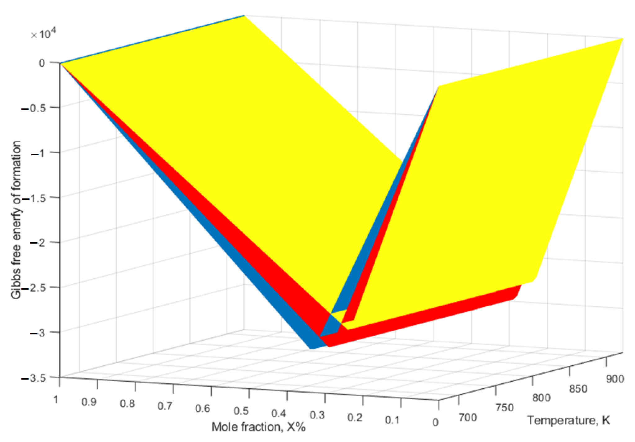
4. The Thermodynamic and Kinetics of IMC Formation and Growth

It is reported that the diffusion of Al into iron occurs only when the temperature is above the melting point of Al. At temperatures below the melting point of Al, iron diffuses into Al more than Al does into Fe [60]. In the FSW of dissimilar metals, the diffusion of atoms begins immediately after intimate contact between the two metals behind the pin [60]. The temperature does not reach the melting point of aluminum; therefore, only aluminum-rich phases such as Fe2Al5 and Fe4Al13 are formed in solid-state welding processes [60]. For the formation of IMCs at any location, two conditions should be met: first, the chemical composition at that location should be close to that of the corresponding IMC. Second, the Gibbs free energy for the formation of that IMC should be lowest at that temperature. These criteria should be modified because the composition in the transition zone changes gradually, and the first condition is not satisfied for all IMCs at the same time. The Gibbs free energy of formation ( Δ G T 0 ) at any temperature T is obtained with
Δ G T 0 = Δ H T   0 T Δ S T 0
Δ H T 0 is the enthalpy of formation, and Δ S T 0 is the entropy of formation. It has been shown that Δ H T 0 is independent of temperature ( Δ H T 0 = Δ H 298 0 ) , and the effect of entropy on the free energy during solid-state interactions is negligible at all temperatures ( T Δ S T 0 Δ H T 0 ) [61]. Therefore,
Δ G T 0 = Δ H 298 0  
The value of enthalpy is given per mole of the product. If the initial atoms are not present in stoichiometric quantity (as is the case on the contact surfaces of the welded dissimilar metals), the value of enthalpy becomes lower. In this way, the value of enthalpy is determined via the limiting element and is obtained with
Δ H = Δ H   × effective   concentration   of   limiting   element compound   concentration   of   limiting   element
The values of enthalpy for different kinds of Al-Fe IMCs are as follows [61]:
Δ H Fe 4 Al 13 = 38 , 733.42 + 16.05 T   0.94 × 1028 ×   T 9
Δ H Fe 2 Al 5 = 40 , 141.13 + 15.04 T   0.88 × 1028 ×   T 9
Δ H FeAl 2 = 39 , 687.25 + 13.75 T   0.82 × 1028 ×   T 9
The values of enthalpy as a function of composition and temperature are shown in Figure 9. The temperature range was chosen between 600 and 900 K, which is the typical temperature for the FSW of Al to St. As can be seen, the enthalpy values are not temperature dependent, so the temperature during welding is not crucial for the type of IMCs. The lowest energy corresponds to FeAl2, but as mentioned earlier, this is not the first phase to appear at the interface.
The first phase that appears is the one with the lowest effective free energy of formation at the composition of the lowest eutectic in the binary phase diagram [62]. This can be explained by the dependence of the diffusion rate on the local composition. It is known that the diffusion rate depends on the local melting temperature [62]. The lower the local melting temperature, the higher the diffusion rate at this point [62]. According to the Al-Fe phase diagram shown in Figure 7, the composition with the lowest eutectic temperature (i.e., the lowest melting temperature) occurs at 0.02 atomic % iron. When the local composition approaches the composition with the lower melting temperature, the diffusion rate is high, and, therefore, the composition is more likely to change in this range. For the composition near the lowest eutectic point, the diffusion rate is high, so the local composition reaches this point faster. In fact, the IMCs closest to the lowest eutectic point are formed first. In other words, the Gibbs free energy of the IMCs at the composition of the lowest eutectic would be the criterion for predicting the phase that occurs first. Figure 9 shows that Fe4Al13 has the lowest energy and therefore occurs first.
The first phase that forms is Fe4Al13, but it disappears after some time of heat treatment at 773 K. This is because the diffusion of iron causes the composition to approach that of Fe2Al5 [42]. In this state of composition, Fe2Al5 has the lowest energy and is therefore more stable. At temperatures below 1173 K, the IMC phase formed between Al and Fe is Fe2Al5 [22]. Other IMCs such as FeAl and Fe3Al form at temperatures above 1273 K. This is expected based on the above explanations since Al-rich regions accumulate Fe faster than Fe-rich regions accumulate Al. FeAl3 can form simultaneously with Fe2Al5, but this phase disappears at the expense of Fe2Al5 formation.
After the nucleation of IMCs, the growth process begins, which occurs via diffusion across interfaces and within phases. Diffusion across the interface depends on two factors: first, on the difference in the chemical potential of the elements on both sides of the interface, and second, on the structure of the interface, which determines the mobility of the atoms across the interface. The phase boundary moves when the IMCs grow. If the flux of atoms is the same in both directions, there is no movement of the boundary. However, since the diffusion rates of the two elements are not equal, the initial interface moves in both directions. The rate of the movement of the interface φ between the two phases δ and γ is obtained using [63]
φ = j i δ j i γ c i δ c i γ  
where j i δ and j i γ denote the inter-diffusion fluxes of component i , and c i δ and c i γ denote the concentration of component i at the interface of δ and γ . The velocity of the interface movement can be controlled via the volume diffusion inside the phases and/or the interface diffusion. The IMC phases have an incoherent interface in order to minimize the strain energy at the interface [64]. This causes a high mobility of atoms across the interface, and, therefore, the diffusion rate at the interface is high. This causes both phases at the two sides of the interface ( c i δ and c i γ ) to have a composition close to the equilibrium state between the two phases, and, therefore, the value of c i δ c i γ is the maximum. In this condition, the interdiffusion currents of the components are determined via the diffusion of the individual elements within the phases and not by the diffusion across the interface of the phases.
The rate constant of growth of each IMC is independent of the adjacent phases [65]. For example, if Fe2Al5 is formed between Al and Fe or between Fe4A113 and Fe, the same rate constant applies to both cases. In other words, this constant depends on the growing phase and is not sensitive to the adjacent phases. This is due to the higher diffusion rate of elements at the interface, which leads to the diffusion within the phases being the determining factor. For example, it is reported that the diffusion rate of Fe and Al atoms at the interface between Fe3Al and steel is greater than the diffusion within the IMCs and steel [35]. The growth of all Al-Fe IMCs is controlled by the diffusion of Fe atoms into Al-richer IMCs [22]. This means that in Equation (1), the speed of the interface movement is dependent on the difference in the fluxes of atoms at the interface, which is itself controlled by the diffusion rate within the IMCs. The thickness of IMCs ( Δ x ) is obtained using [66]
Δ x 2 = 2   k t  
where k is a constant that is dependent on temperature, and t is time. k is obtained using [66]
k = k 0   e x p E a R T
where k 0 is a constant, and E a is the activation enthalpy. When the growth of an IMC layer follows a parabolic pattern, it is controlled by the volume diffusion of the constituent elements in each phase. The rate constant of growth is dependent on the interdiffusion constant D . , which itself is dependent on the diffusion constants of every element and is obtained via
D . = X A l D F e + X F e D A l
where X A l and X F e are the concentrations of Al and Fe atoms, and D F e and D A l are the diffusion constants of Fe and Al. The interdiffusion coefficient in Fe2Al5 is larger than those of other Al-Fe IMCs in the temperature range of 823–913 K [67]. The equations for the growth of some of the Al-Fe IMCs are provided in Table 2. As is observed, the constant of the growth rate for Fe2Al5 is higher than that for Fe4Al13. (Please note the parametric formula used for the prediction of growth and its slight difference from Equation (8), which yields a different k value.)

5. IMCs during FSW and Other Solid-State Bonding Processes

Table 3 compiles and presents various data on IMCs formed during the friction stir lap welding of various Al alloys and St grades. The thicknesses of the IMCs, the types of IMCs, the reported times and peak temperatures during welding, and the methods used to characterize the IMCs are given for each blank. For comparison, these data are given in Table 4 for some other solid-state welding methods. Table 5 shows these data for FSW in the butt configuration.
As can be observed, different types of IMCs are reported in each paper. To identify where these differences come from, aluminum alloys were categorized based on their alloying elements in each series. Steels were divided into three categories: interstitial-free steels (IF steels), carbon steels, and stainless steels. The highest reported thicknesses of the IMCs were shown for each combination in Figure 10. The thinnest IMC layers are found in stainless steel and AA6XXX. In the case of austenitic stainless steel, Ni diffuses into Al along with Fe and is present in the Al-Fe IMC layer. This retards the diffusion process and the growth of IMCs [110]. This does not mean that the thickness of IMCs cannot be controlled for other types of steel. Nevertheless, some precautions are needed to achieve this goal, such as in underwater FSW. Derazkola et al. [103] reported a decrease in IMC thickness from 7 μm to 1 μm when using water as a cooling medium in FSW. They reported a decrease in temperature from 1015 to 883 K, while other authors reported a peak temperature of 853 K and thicknesses of 1–4 μm, even without a cooling medium [100].
The average thicknesses of the IMC layers formed during the FSW of Al/St with various Al and St alloys are presented in Figure 11. As can be seen, stainless steel results in the lowest thickness among the St alloys. Among the Al alloys, AA6XXX yields the lowest IMC thickness.
Based on the data in Table 3 and Table 5, the formation of Fe2Al5 and FeAl3 is more likely during the FSW of Al to carbon steel. Some of the literature reports that FeAl3 is not stable and disappears at the expense of Fe2Al5 [61]. The diffusion rate of Fe atoms into the initially formed FeAl3 is higher than the diffusion rate of Al atoms. Therefore, the concentration of Fe increases after a while, and the thermodynamical conditions favor the formation of Fe2Al5. These IMCs are brittle and have low ductility. Therefore, the joint strength of Al to carbon steel joints is always low unless the thicknesses of the IMCs are controlled or these IMCs are dispersed in some way.
According to the literature, the main phase that is present in almost every Al-Fe FSW joint is Fe2Al5. This phase is also a dominant phase in diffusion couples and other Fe-rich IMCs formed at a temperature higher than 600 °C [117]. The growth kinetics of this phase is also higher than that of FeAl3 [118]. FeAl2 is only observed in some reports because it grows slower than the other IMCs and is reported to be barely seen in diffusion pairs [43]. Based on the diagram of formation enthalpy in Figure 9, the essential concentration for the formation of FeAl2 is about 33 atomic % Fe. The formation of FeAl2 is suppressed by the growth of Fe2Al5 due to its high growth rate. FeAl2 can form after annealing at high temperatures and sufficient time, as further diffusion of Fe atoms causes the local composition to approach the composition of FeAl2, reducing the Gibbs energy for the formation of this phase and allowing this phase to be observed at the interface, as shown in [101].
The tool offset can change the IMCs in the FSW joining of aluminum to steel, leading to the formation of iron-rich IMCs such as Fe3Al [99]. In Al-St joining, some offset of the pin from the steel is required to facilitate oxide removal and the plastic deformation of the steel. This misalignment should be limited to avoid severe mixing of the two materials around the pin and to control the temperature. Figure 12 shows the schematic representation of the FSW process in the overlap and butt configurations. The offset of the pin in the butt configuration is shown. The dispersion of iron particles in the aluminum matrix is due to this offset. These dispersed particles convert from their outer surface to IMCs due to the process heat. Behind the pin, the aluminum is forged onto the fresh steel surface, and a metallurgical bond is formed between the aluminum and steel. Therefore, the growth of a continuous IMC layer is promoted in this area, which is below the shoulder. The growth continues as long as this area is below the shoulder, and, therefore, the welding speed can control the thickness of the IMC layer. Tanaka et al. [93] report that the growth of IMCs starts at the stage when the pin is in contact with the material. However, the IMCs formed are dispersed into the matrix during the contact of the pin, as is schematically shown in Figure 12. This means that the growth of the continuous IMC layers at the interface starts only after the pin. Therefore, the time available for calculating IMC thicknesses is the duration of which the shoulder is in contact with the surface.
This shows the importance of the welding speed for the thickness of IMCs during FSW. Moreover, Rafiei et al. [105] reported that in the FSW of AA5083/A316L, the peak temperature is not affected by the welding speed, but the time spent at this temperature affects the growth and thickness of the IMCs. Figure 13 shows the schematic of Al-Fe IMC formation during the FSW of Al to St. This mechanism is the most widely accepted mechanism via which IMCs are formed.
The alloying elements of aluminum and steel can also affect the thickness of IMCs at the interface. The reported thicknesses of IMCs during the FSW of different aluminum–steel welds are shown in Table 3 and Table 5. Among the aluminum alloys, pure aluminum and AA5XXX have the greatest IMC layer thicknesses when welded to very-low-carbon steel or carbon steel. On the other hand, AA6XXX forms a thin IMC layer (thinner than 2 μm) when welded to any steel grade. This is in line with the results presented in Figure 11. One reason for this is that Si is present as an alloying element in this aluminum. Si, as a substitutional alloying element in aluminum, retards the growth kinetics of Al-Fe IMCs due to its effect of reducing the diffusion coefficient [119]. Si is present in AA6XXX in the form of both solid solutions and Mg2Si precipitates. During the FSW of aluminum, the Mg2Si precipitates dissolve due to the high welding temperatures, which increases the Si concentration in the form of solid solutions. This Si in the solid solution occupies the vacancies in the aluminum and reduces the diffusion rates of other elements such as iron. Even after the formation of Al-Fe IMCs, this Si is present in IMC layers, occupying the substitution sites and reducing the growth rate of these IMC layers. In a study by Dangi et al. [117], the presence of a concentration gradient of Si in the IMC layer of Fe2Al5 is interpreted as a low diffusion coefficient of Si in this phase. Since Si occupies the vacancies, it retards the diffusion of iron atoms in the IMC phase. The quasi-binary phase diagram for Fe-71 at% Al-Si is shown in Figure 14. The composition range of Al and Fe was chosen to be around Fe2Al5. The temperature composition range during the FSW process is plotted in this figure. As can be seen, Fe2Al5 has a high solubility of up to 0.4 at% silicon at a temperature of 1000 K. Considering the Si content in the transition layer, which is in the range of 0.5–2.5 at% [120], the Fe2Al5 is supersaturated with respect to Si. At the temperature of FSW, precipitation of Si-containing IMCs such as FeAlSi is unlikely because no report indicates the presence of this phase. Therefore, this Si is present in Fe2Al5 as a solid solution, and the diffusion coefficient is strongly affected. The retarding effect of Si on the growth of Al-Fe IMCs has been reported in previous studies [119]. Lauria et al. [121] also reported the hindering behavior of solid solutions on the growth of IMCs. It was reported that the thickness of Al-Fe IMCs was larger in the welding of AA5083 to steel than in the FSW of AA6061 to steel [71]. This was attributed to the higher Si content in AA6061, proving the effect of Si on the growth of IMCs. The same reason applies to the AA7XXX series, in which Cu plays the same role as Si. Yousaf et al. [122] reported a decrease in IMC thickness due to the presence of Cu in diffusion pairs.
It should be noted that the presence of Si in aluminum alloys does not necessarily guarantee low growth kinetics of the Al-Fe-IMCs. Chen et al. [85] obtained a high thickness of Al-Fe IMCs between Al-AC4C and mild steel, although the cast aluminum contains more than 7% Si. This is because this Si is present as a separate phase and is dispersed but not dissolved during FSW.
In the case of stainless steel, Ni and Cr can diffuse into aluminum together with Fe and slow down the diffusion rate like Si. Even at high temperatures, when Al is in a thixotropic state, the growth of IMCs at the stainless-steel interface is limited [90]. Elements such as Si, V, Cr, Mn, Co, Ni, Cu, and Zn have high solubility in Al-Fe-IMCs [124]. This can affect the interdiffusion coefficient, which, in turn, can lead to a decrease in the kinetics of the IMCs. In the FSW of stainless steel to Al, the thickness of the IMC layer was less than in the FSW of carbon steel to Al, resulting in a higher strength of the stainless steel and Al joints [59]. This was attributed to the presence of Ni and Cr. The same result was observed when carbon steel was buttered with stainless steel and then welded with Al [16]. The solutes in IMCs may also affect the tensile strength of the IMCs. Cr is reported to have no effect on the hardness of Al-Fe IMCs [125]. Fleischer proposed the following equation to calculate the increase in tensile strength ( Δ σ ) due to a solid solution [126]:
Δ σ = η M μ ε 1.5 C 0.5  
where η is a constant, M is the Tailor factor, ε is the misfit parameter, μ is the shear modulus, and C is the concentration of the solute element. Although this relationship is used for metals, it can also be used as a reference to describe the strengthening of Al-Fe IMCs via solute atoms. However, the solute atoms may have other effects, such as on grain size. This makes it difficult to determine the contribution of the solid solution to the strength.

6. Al-Fe IMCs and Fracture Behavior

The formation of IMCs during FSW is inevitable, as they are an indicator of a metallurgical bond between the two materials. In other words, the presence of IMCs at the interface guarantees the bond. On the other hand, IMCs represent the weak points in joints. Low ductility and low tensile strength are the characteristics of Al/St joints produced via FSW when a fracture propagates through the IMC layer [95]. Al-Fe IMCs are brittle and, therefore, the joints usually fail at the interface. Due to strain concentration in the joint and the brittleness of the IMCs, the total elongation of the joints is usually very low. In cases in which the joint strength is higher than that of the base material due to proper control of the IMCs, the specimens fail due to the base material during tensile testing, making it difficult to characterize the joint strength.
The most conventional method for evaluating the strength of joints is to use standard tensile specimens for bulk materials. In these cases, the joint line is located in the center of the gauge. When the interfacial strength is less than that of the base material, these tests provide useful information about the joint and the IMCs (Figure 15). However, when the interfacial strength is high, the conventional tensile specimens are likely to fail due to the weaker base material (usually aluminum) without providing any information about the fracture behavior of the joint. Different solutions have been applied to cause a fracture in the bond line so that the contribution of IMCs to the fracture can be understood. Figure 16 shows a schematic of the tensile specimen used to evaluate the effect of IMCs on the bond strength between Al and St. Due to the hole in the center of the specimen where the bond line is located, it is more likely that fracture will occur through the IMC layer, so the contribution of the IMCs to fracture can be evaluated.
Micro-scale tensile testing is another method for evaluating the interfacial strength between Al and St. An example of this, carried out using focused ion beam–scanning electron microscopy, is shown in Figure 17. Pre-cracks are formed at various locations to investigate the fracture behavior of the IMCs as well as the interfaces.
The mechanism of failure of Al/St joints was investigated using fractography and microstructure images. The interface between IMCs and steel is mentioned as the preferred path of crack propagation (Figure 18) [59]. This was attributed to the low surface energy of Fe2Al5 (η) and St, which allows easy debonding under normal loading conditions.
The lap joints of Al/St made via FSW are under shear loading during tensile testing. Due to the presence of defects and voids and also the mode of loading, the joints are vulnerable to fracture, not because of IMCs, but because of the voids [57]. Moreover, interlocking plays an important role in joint strength with respect to butt joining where a metallurgical bond is important [128]. Figure 19 shows the interface of Al/St joined in the lap configuration using FSW, wherein mechanical interlocking caused by an upward flow of materials is obvious. There are also reports that no IMC exists at the interface of a lap joint and that only the mechanical interlocking caused by a wave shape of the interface is responsible for the joint strength [129].
These results indicate that in the overlap configuration, the IMCs have no effect on the strength of the joint, since in some cases IMCs were not present, or if they were present, they were not observed or were observed only a little at the fracture surface. In contrast, in the butt configuration, the IMCs play the main role in the fracture behavior and strength of the joints.
The contributions of elements to the IMCs during the FSW of dissimilar materials was explored in the current review paper, with a focus on aluminum–steel joining. However, it is still necessary to study the effects of different elements such as Cr, Ni, Mo, etc., both individually and in combination. Synergetic effects may exist when combining these elements. In particular, the fatigue strength of dissimilar joints, which is the main drawback of these joints, can be improved using this technique, eliminating an important obstacle in the FSW of dissimilar materials.

7. Further Exploration

Although it is known that the fracture probably propagates through the Al-Fe IMCs, some details about the mechanism of this fracture are still unknown. Usually, more than one IMC is present at the Al/St interface, and it is not clear through which layer or interfaces the fracture propagates. To find out, a detailed phase analysis along with accurate fractography is required. Several studies have been performed to control the thickness of IMCs to improve the strength of the joints. However, other aspects of IMCs, such as grain size or chemical composition, have not been studied. The engineering design of IMC layers needs further investigation so that the grain size of the IMCs can be refined to improve the fracture toughness of the IMCs. In addition, the chemical composition of IMCs can be changed to increase their strength via solid solution strengthening. The alloying elements can also hinder the kinetics of IMC growth so that the thickness of an IMC can be effectively controlled. The thermodynamics and kinetics of Al-Fe IMCs in the presence of various elements also need to be explored. This is particularly important for the FSW of different Al alloys to different alloy steels, such as stainless steels.

8. Summary

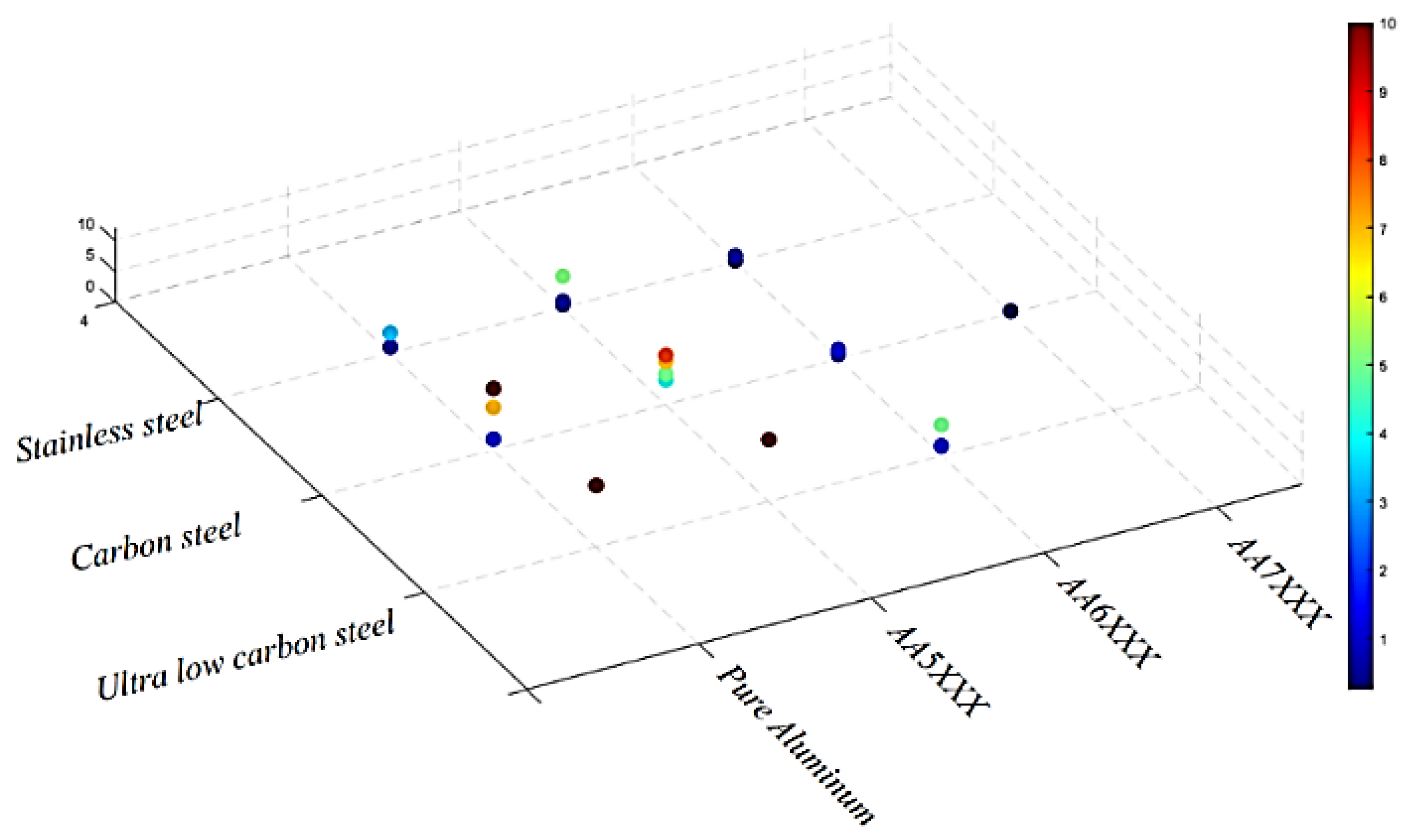
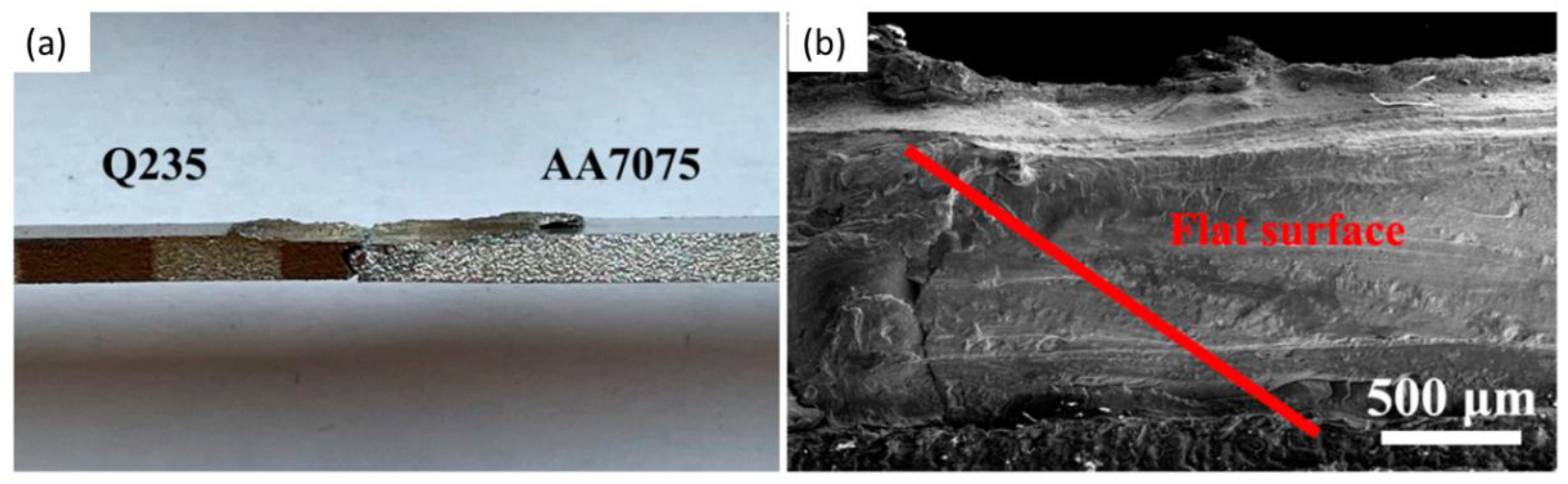
  • During the FSW of aluminum to steel, iron-rich IMCs such as Fe2Al5 and FeAl3 are the present phases at the interface, though the thickness of Fe2Al5 is prevalent. Other Fe-Al IMCs are rarely seen at the interface, except when the tool offset in steel is high or heat treatment is applied on the welded specimens.
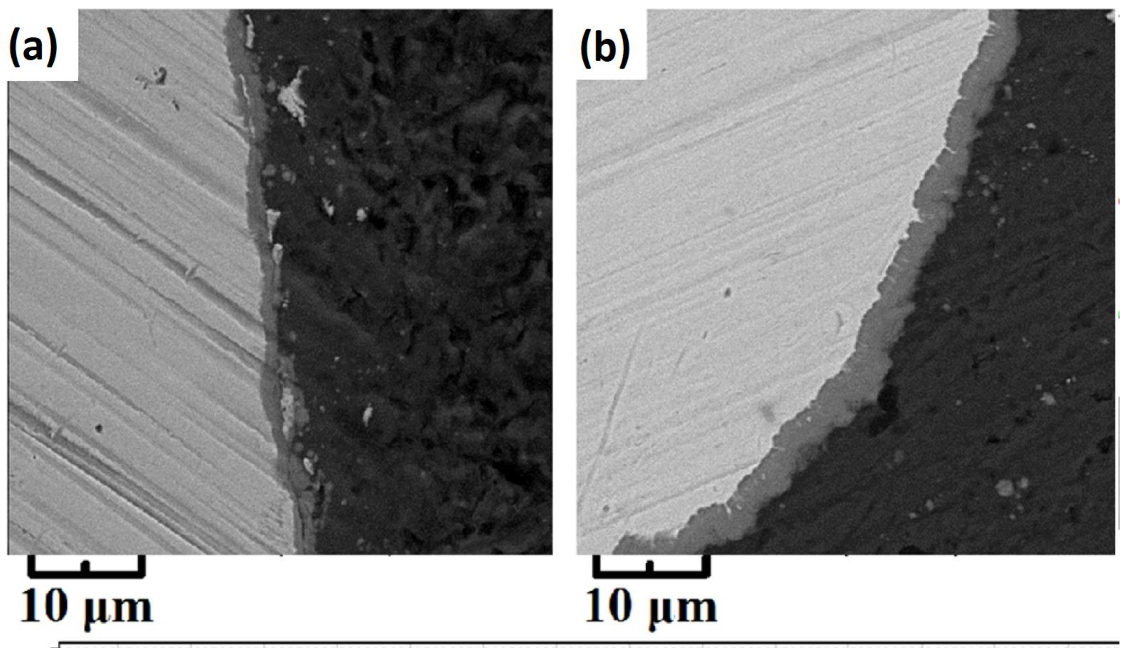
  • Among the alloying elements in aluminum that can influence the growth rate of Fe-Al IMCs, Si has the highest effect. In aluminum alloys in which at the temperature of the FSW, Si is present as a solid solution element, such as in the 6XXX series, the growth of IMCs is retarded. The reported thickness of the IMCs, in this case, is lower than 4 μm.
  • IF steels and carbon steels form IMCs of a high thickness during FSW to aluminum, though the thickness range in carbon steels is smaller.
  • The alloying element of stainless steel has a great lowering effect on the thickness of IMCs during FSW. Ni and Cr retard the diffusion. They may also contribute to the toughening of the IMCs via solid solution strengthening as well as the grain refinement of the IMCs.
  • IMCs have a high effect on the fracture mechanism in butt welds of Al/St, but their contribution to the fracture behavior in the lap configuration is low.

Author Contributions

Conceptualization, R.B. and I.G.; Methodology, A.A.-S.; Writing—R.B. and I.G.; Writing—review and editing, L.F.M.d.S., A.A.-S., H.P. and V.F.; Supervision, L.F.M.d.S. All authors have read and agreed to the published version of the manuscript.

Funding

The authors gratefully acknowledge the funding under the reference “UIDP/50022/2020—LAETA—Laboratório Associado de Energia, Transportes e Aeronáutica”. This research is also sponsored by FEDER funds through the program COMPETE—Programa Operacional Factores de Competitividade, and by national funds through FCT—Fundação para a Ciência e a Tecnologia, under the projects UIDB/00285/2020 and LA/P/0112/2020.

Institutional Review Board Statement

Not applicable.

Informed Consent Statement

Not applicable for this study.

Data Availability Statement

Not applicable.

Conflicts of Interest

The authors declare that they have no known competing financial interest or personal relationship that could have appeared to influence the work reported in this paper.

References

  1. Raabe, D.; Tasan, C.C.; Olivetti, E.A. Strategies for improving the sustainability of structural metals. Nature 2019, 575, 64–74. [Google Scholar] [CrossRef] [Green Version]
  2. Nanda, T.; Singh, V.; Singh, V.; Chakraborty, A.; Sharma, S. Third generation of advanced high-strength steels: Processing routes and properties. Proc. Inst. Mech. Eng. Part L J. Mater. Des. Appl. 2019, 233, 209–238. [Google Scholar] [CrossRef]
  3. Kleinbaum, S.; Jiang, C.; Logan, S. Enabling sustainable transportation through joining of dissimilar lightweight materials. MRS Bull. 2019, 44, 608–612. [Google Scholar] [CrossRef] [Green Version]
  4. Kusuda, Y. Honda develops robotized FSW technology to weld steel and aluminum and applied it to a mass-production vehicle. Ind. Robot Int. J. 2013, 40, 208–212. [Google Scholar] [CrossRef]
  5. Kim, J.H.; Wang, L.S.; Putta, K.; Haghighi, P.; Shah, J.J.; Edwards, P. Knowledge based design advisory system for multi-material joining. J. Manuf. Syst. 2019, 52, 253–263. [Google Scholar] [CrossRef]
  6. Howlader, M.; Kaga, T.; Suga, T. Investigation of bonding strength and sealing behavior of aluminum/stainless steel bonded at room temperature. Vacuum 2010, 84, 1334–1340. [Google Scholar] [CrossRef]
  7. Ortega-Iguña, M.; Akhavan-Safar, A.; Carbas, R.; Sánchez-Amaya, J.; Chludzinski, M.; da Silva, L. Use of seawater to improve the static strength and fatigue life of bonded coated steel joints. Polym. Degrad. Stab. 2022, 206, 110169. [Google Scholar] [CrossRef]
  8. Delzendehrooy, F.; Akhavan-Safar, A.; Barbosa, A.; Beygi, R.; Cardoso, D.; Carbas, R.; Marques, E.; da Silva, L. A comprehensive review on structural joining techniques in the marine industry. Compos. Struct. 2022, 289, 115490. [Google Scholar] [CrossRef]
  9. Akhavan-Safar, A.; Bozchaloei, G.E.; Jalali, S.; Beygi, R.; Ayatollahi, M.R.; da Silva, L.F. Impact Fatigue Life of Adhesively Bonded Composite-Steel Joints Enhanced with the Bi-Adhesive Technique. Materials 2023, 16, 419. [Google Scholar] [CrossRef]
  10. Do Vale, G.P.; Akhavan-Safar, A.; de Castro Lopes, F.V.B.; Sousa, F.C.; Goyal, R.; Jennings, J.; da Silva, L.F. Effects of Mode Mixity on the Failure Mechanism of Aged Adhesive Joints. J. Mech. Solids 2022, 1, 31–38. [Google Scholar] [CrossRef]
  11. Beygi, R.; Akhavan-Safar, A.; Carbas, R.; Barbosa, A.; Marques, E.; da Silva, L. Utilizing a ductile damage criterion for fracture analysis of a dissimilar aluminum/steel joint made by friction stir welding. Eng. Fract. Mech. 2022, 274, 108775. [Google Scholar] [CrossRef]
  12. Wang, H.; Hu, X.; Jiang, X. Effects of Ni modified MWCNTs on the microstructural evolution and shear strength of Sn-3.0 Ag-0.5 Cu composite solder joints. Mater. Charact. 2020, 163, 110287. [Google Scholar] [CrossRef]
  13. Hu, X.; Xu, T.; Keer, L.M.; Li, Y.; Jiang, X. Shear strength and fracture behavior of reflowed Sn3.0Ag0.5Cu/Cu solder joints under various strain rates. J. Alloys Compd. 2017, 690, 720–729. [Google Scholar] [CrossRef]
  14. Bi, X.; Hu, X.; Li, Q. Effect of Co addition into Ni film on shear strength of solder/Ni/Cu system: Experimental and theoretical investigations. Mater. Sci. Eng. A 2020, 788, 139589. [Google Scholar] [CrossRef]
  15. Zhang, Z.; Hu, X.; Jiang, X.; Li, Y. Influences of mono-Ni (P) and dual-Cu/Ni (P) plating on the interfacial microstructure evolution of solder joints. Metall. Mater. Trans. A 2019, 50, 480–492. [Google Scholar] [CrossRef]
  16. Beygi, R.; Carbas, R.; Barbosa, A.; Marques, E.; da Silva, L. Buttering for FSW: Enhancing the fracture toughness of Al-Fe intermetallics through nanocrystallinity and suppressing their growth. J. Manuf. Process. 2023, 90, 233–241. [Google Scholar] [CrossRef]
  17. Beygi, R.; Kazeminezhad, M.; Kokabi, A.; Loureiro, A. Friction stir welding of Al-Cu bilayer sheet by tapered threaded pin: Microstructure, material flow, and fracture behavior. Metall. Mater. Trans. A 2015, 46, 2544–2553. [Google Scholar] [CrossRef]
  18. Beygi, R.; Kazeminezhad, M.; Kokabi, A. Microstructural evolution and fracture behavior of friction-stir-welded Al-Cu laminated composites. Metall. Mater. Trans. A 2014, 45, 361–370. [Google Scholar] [CrossRef]
  19. Beygi, R.; Kazeminezhad, M.A.; Kokabi, A. Butt joining of Al–Cu bilayer sheet through friction stir welding. Trans. Nonferrous Met. Soc. China 2012, 22, 2925–2929. [Google Scholar] [CrossRef]
  20. Beygi, R.; Mehrizi, M.Z.; Akhavan-Safar, A.; Safaei, S.; Loureiro, A.; da Silva, L. Design of friction stir welding for butt joining of aluminum to steel of dissimilar thickness: Heat treatment and fracture behavior. Int. J. Adv. Manuf. Technol. 2021, 112, 1–14. [Google Scholar] [CrossRef]
  21. Li, Y.; Liu, Y.; Yang, J. First principle calculations and mechanical properties of the intermetallic compounds in a laser welded steel/aluminum joint. Opt. Laser Technol. 2020, 122, 105875. [Google Scholar] [CrossRef]
  22. Kobayashi, S.; Yakou, T. Control of intermetallic compound layers at interface between steel and aluminum by diffusion-treatment. Mater. Sci. Eng. A 2002, 338, 44–53. [Google Scholar] [CrossRef]
  23. Zhang, M.; Wang, Y.; Xue, P.; Zhang, H.; Ni, D.; Wang, K.; Ma, Z. High-quality dissimilar friction stir welding of Al to steel with no contacting between tool and steel plate. Mater. Charact. 2022, 191, 112128. [Google Scholar] [CrossRef]
  24. Tanaka, T.; Nezu, M.; Uchida, S.; Hirata, T. Mechanism of intermetallic compound formation during the dissimilar friction stir welding of aluminum and steel. J. Mater. Sci. 2020, 55, 3064–3072. [Google Scholar] [CrossRef]
  25. Beygi, R.; Carbas, R.; Queiros, A.; Marques, E.; Shi, R.; da Silva, L. Comparative study between stainless steel and carbon steel during dissimilar friction stir welding with aluminum: Kinetics of Al–Fe intermetallic growth. Met. Mater. Int. 2021, 2021, 1–12. [Google Scholar] [CrossRef]
  26. Mortello, M.; Pedemonte, M.; Contuzzi, N.; Casalino, G. Experimental investigation of material properties in FSW dissimilar aluminum-steel lap joints. Metals 2021, 11, 1474. [Google Scholar] [CrossRef]
  27. Batistao, B.F.; Bergmann, L.A.; Gargarella, P.; de Alcantara, N.G.; dos Santos, J.F.; Klusemann, B. Characterization of dissimilar friction stir welded lap joints of AA5083 and GL D36 steel. J. Mater. Res. Technol. 2020, 9, 15132–15142. [Google Scholar] [CrossRef]
  28. Hussein, S.A.; Hadzley, A. Characteristics of aluminum-to-steel joint made by friction stir welding: A review. Mater. Today Commun. 2015, 5, 32–49. [Google Scholar] [CrossRef]
  29. Mehta, K.P. A review on friction-based joining of dissimilar aluminum–steel joints. J. Mater. Res. 2019, 34, 78–96. [Google Scholar] [CrossRef] [Green Version]
  30. Rizlan, M.Z.; Abdullah, A.B.; Hussain, Z. A comprehensive review on pre-and post-forming evaluation of aluminum to steel blanks via friction stir welding. Int. J. Adv. Manuf. Technol. 2021, 114, 1871–1892. [Google Scholar] [CrossRef]
  31. Safeen, M.W.; Spena, P.R. Main issues in quality of friction stir welding joints of aluminum alloy and steel sheets. Metals 2019, 9, 610. [Google Scholar] [CrossRef] [Green Version]
  32. Haidara, F.; Record, M.-C.; Duployer, B.; Mangelinck, D. Phase formation in Al–Fe thin film systems. Intermetallics 2012, 23, 143–147. [Google Scholar] [CrossRef]
  33. Mahto, R.P.; Pal, S.K. Friction stir welding of dissimilar materials: An investigation of microstructure and nano-indentation study. J. Manuf. Process. 2020, 55, 103–118. [Google Scholar] [CrossRef]
  34. Stoloff, N.S.; Sikka, V.K. Physical Metallurgy and Processing of Intermetallic Compounds; Springer: Berlin/Heidelberg, Germany, 2012. [Google Scholar]
  35. Yajiang, L.; Juan, W.; Yansheng, Y.; Haijun, M. Diffusivity of Al and Fe near the diffusion bonding interface of Fe 3 Al with low carbon steel. Bull. Mater. Sci. 2005, 28, 69–74. [Google Scholar] [CrossRef]
  36. Ozaki, H.; Kutsuna, M. Chapter 2: Dissimilar metal joining of zinc coated steel and aluminum alloy by laser roll welding. Weld. Process. 2012, 2, 33–54. [Google Scholar]
  37. Eggersmann, M.; Mehrer, H. Diffusion in intermetallic phases of the Fe-Al system. Philos. Mag. A 2000, 80, 1219–1244. [Google Scholar] [CrossRef]
  38. Salazar, M.; Albiter, A.; Rosas, G.; Pérez, R. Structural and mechanical properties of the AlFe intermetallic alloy with Li, Ce and Ni additions. Mater. Sci. Eng. A 2003, 351, 154–159. [Google Scholar] [CrossRef]
  39. Deevi, S.; Sikka, V. Nickel and iron aluminides: An overview on properties, processing, and applications. Intermetallics 1996, 4, 357–375. [Google Scholar] [CrossRef]
  40. Villars, P.; Okamoto, H. Inorganic Solid Phases; Springer: Berlin/Heidelberg, Germany, 2016. [Google Scholar]
  41. Shiran, M.K.G.; Khalaj, G.; Pouraliakbar, H.; Jandaghi, M.; Bakhtiari, H.; Shirazi, M. Effects of heat treatment on the intermetallic compounds and mechanical properties of the stainless steel 321–aluminum 1230 explosive-welding interface. Int. J. Miner. Metall. Mater. 2017, 24, 1267–1277. [Google Scholar] [CrossRef]
  42. Jindal, V.; Srivastava, V. Growth of intermetallic layer at roll bonded IF-steel/aluminum interface. J. Mater. Process. Technol. 2008, 195, 88–93. [Google Scholar] [CrossRef]
  43. Li, X.; Scherf, A.; Heilmaier, M.; Stein, F. The Al-rich part of the Fe-Al phase diagram. J. Phase Equilibria Diffus. 2016, 37, 162–173. [Google Scholar] [CrossRef] [Green Version]
  44. Mondolfo, L.F. Aluminum Alloys: Structure and Properties; Elsevier: Amsterdam, The Netherlands, 2013. [Google Scholar]
  45. Kim, S.-H.; Kim, H.; Kim, N.J. Brittle intermetallic compound makes ultrastrong low-density steel with large ductility. Nature 2015, 518, 77–79. [Google Scholar] [CrossRef]
  46. Zandsalimi, S.; Heidarzadeh, A.; Saeid, T. Dissimilar friction-stir welding of 430 stainless steel and 6061 aluminum alloy: Microstructure and mechanical properties of the joints. Proc. Inst. Mech. Eng. Part L J. Mater. Des. Appl. 2019, 233, 1791–1801. [Google Scholar] [CrossRef]
  47. Grujicic, M.; Snipes, J.; Ramaswami, S.; Galgalikar, R.; Yen, C.; Cheeseman, B. Computational analysis of the intermetallic formation during the dissimilar metal aluminum-to-steel friction stir welding process. Proc. Inst. Mech. Eng. Part L J. Mater. Des. Appl. 2019, 233, 1080–1100. [Google Scholar] [CrossRef] [Green Version]
  48. Borrisutthekul, R.; Yachi, T.; Miyashita, Y.; Mutoh, Y. Suppression of intermetallic reaction layer formation by controlling heat flow in dissimilar joining of steel and aluminum alloy. Mater. Sci. Eng. A 2007, 467, 108–113. [Google Scholar] [CrossRef]
  49. Wahid, M.A.; SIDDIQUEE, A.N. Review on underwater friction stir welding: A variant of friction stir welding with great potential of improving joint properties. Trans. Nonferrous Met. Soc. China 2018, 28, 193–219. [Google Scholar] [CrossRef]
  50. Garg, T.; Mathur, P.; Singhal, V.; Jain, C.; Gupta, P. Underwater friction stir welding: An overview. Int. Rev. Appl. Eng. Res. 2014, 4, 165–170. [Google Scholar]
  51. Yılmaz, M.; Çöl, M.; Acet, M. Interface properties of aluminum/steel friction-welded components. Mater. Charact. 2002, 49, 421–429. [Google Scholar] [CrossRef]
  52. Thomä, M.; Wagner, G.; Straß, B.; Wolter, B.; Benfer, S.; Fürbeth, W. Ultrasound Enhanced Friction Stir Welding (USE-FSW) of Hybrid Aluminum/Steel Joints; Springer International Publishing: Cham, Switzerland, 2019; pp. 23–32. [Google Scholar]
  53. Muhamad, M.; Jamaludin, M.; Yusof, F.; Mahmoodian, R.; Morisada, Y.; Suga, T.; Fujii, H. Effects of Al-Ni powder addition on dissimilar friction stir welding between AA7075-T6 and 304 L. Mater. Und Werkst. 2020, 51, 1274–1284. [Google Scholar] [CrossRef]
  54. Derazkola, H.A.; García, E.; Eyvazian, A.; Aberoumand, M. Effects of rapid cooling on properties of aluminum-steel friction stir welded joint. Materials 2021, 14, 908. [Google Scholar] [CrossRef]
  55. Derazkola, H.A.; Eyvazian, A.; Simchi, A. Submerged friction stir welding of dissimilar joints between an Al-Mg alloy and low carbon steel: Thermo-mechanical modeling, microstructural features, and mechanical properties. J. Manuf. Process. 2020, 50, 68–79. [Google Scholar] [CrossRef]
  56. Haghshenas, M.; Abdel-Gwad, A.; Omran, A.; Gökçe, B.; Sahraeinejad, S.; Gerlich, A. Friction stir weld assisted diffusion bonding of 5754 aluminum alloy to coated high strength steels. Mater. Des. 2014, 55, 442–449. [Google Scholar] [CrossRef]
  57. Pourali, M.; Abdollah-Zadeh, A.; Saeid, T.; Kargar, F. Influence of welding parameters on intermetallic compounds formation in dissimilar steel/aluminum friction stir welds. J. Alloys Compd. 2017, 715, 1–8. [Google Scholar] [CrossRef]
  58. Pankaj, P.; Tiwari, A.; Biswas, P. Impact of varying tool position on the intermetallic compound formation, metallographic/mechanical characteristics of dissimilar DH36 steel, and aluminum alloy friction stir welds. Weld. World 2021, 66, 239–271. [Google Scholar] [CrossRef]
  59. Beygi, R.; Carbas, R.; Barbosa, A.; Marques, E.; Da Silva, L. A comprehensive analysis of a pseudo-brittle fracture at the interface of intermetallic of η and steel in aluminum/steel joints made by FSW: Microstructure and fracture behavior. Mater. Sci. Eng. A 2021, 824, 141812. [Google Scholar] [CrossRef]
  60. Watanabe, M.; Feng, K.; Nakamura, Y.; Kumai, S. Growth manner of intermetallic compound layer produced at welding interface of friction stir spot welded aluminum/steel lap joint. Mater. Trans. 2011, 52, 953–959. [Google Scholar] [CrossRef] [Green Version]
  61. Wang, T.; Sidhar, H.; Mishra, R.S.; Hovanski, Y.; Upadhyay, P.; Carlson, B. Evaluation of intermetallic compound layer at aluminum/steel interface joined by friction stir scribe technology. Mater. Des. 2019, 174, 107795. [Google Scholar] [CrossRef]
  62. Pretorius, R.; Marais, T.; Theron, C. Thin film compound phase formation sequence: An effective heat of formation model. Mater. Sci. Rep. 1993, 10, 1–83. [Google Scholar] [CrossRef]
  63. Sisson, R.; Dayananda, M. Diffusion structures in multiphase Cu-Ni-Zn couples. Metall. Mater. Trans. B 1972, 3, 647–652. [Google Scholar] [CrossRef]
  64. Takata, N.; Nishimoto, M.; Kobayashi, S.; Takeyama, M. Crystallography of Fe2Al5 phase at the interface between solid Fe and liquid Al. Intermetallics 2015, 67, 1–11. [Google Scholar] [CrossRef]
  65. Buscaglia, V.; Anselmi-Tamburini, U. On the diffusional growth of compounds with narrow homogeneity range in multiphase binary systems. Acta Mater. 2002, 50, 525–535. [Google Scholar] [CrossRef]
  66. Jindal, V.; Srivastava, V.; Das, A.; Ghosh, R. Reactive diffusion in the roll bonded iron–aluminum system. Mater. Lett. 2006, 60, 1758–1761. [Google Scholar] [CrossRef]
  67. Naoi, D.; Kajihara, M. Growth behavior of Fe2Al5 during reactive diffusion between Fe and Al at solid-state temperatures. Mater. Sci. Eng. A 2007, 459, 375–382. [Google Scholar] [CrossRef]
  68. Liu, J.; Hao, Z.; Xie, Y.; Meng, X.; Huang, Y.; Wan, L. Interface stability and fracture mechanism of Al/Steel friction stir lap joints by novel designed tool. J. Mater. Process. Technol. 2022, 300, 117425. [Google Scholar] [CrossRef]
  69. Chen, Y.; Zhang, F. Improving the quality of dissimilar Al/Steel butt-lap joint via ultrasonic-assisted friction stir welding. Materials 2022, 15, 1741. [Google Scholar] [CrossRef]
  70. Geng, P.; Morimura, M.; Ma, H.; Ma, Y.; Ma, N.; Liu, H.; Aoki, Y.; Fujii, H.; Qin, G. Elucidation of intermetallic compounds and mechanical properties of dissimilar friction stir lap welded 5052 Al alloy and DP590 steel. J. Alloys Compd. 2022, 906, 164381. [Google Scholar] [CrossRef]
  71. Hussein, S.A.; Tahir, A.S.M.; Al-Obaidi, M.A. Evaluation the effects of welding parameters on tri-dissimilar friction stir welds aluminum/steel. Weld. World 2022, 66, 2315–2332. [Google Scholar] [CrossRef]
  72. Movahedi, M.; Kokabi, A.; Reihani, S.S.; Cheng, W.; Wang, C. Effect of annealing treatment on joint strength of aluminum/steel friction stir lap weld. Mater. Des. 2013, 44, 487–492. [Google Scholar] [CrossRef]
  73. Movahedi, M.; Kokabi, A.; Reihani, S.S.; Najafi, H.; Farzadfar, S.; Cheng, W.; Wang, C. Growth kinetics of Al–Fe intermetallic compounds during annealing treatment of friction stir lap welds. Mater. Charact. 2014, 90, 121–126. [Google Scholar] [CrossRef]
  74. Das, H.; Basak, S.; Das, G.; Pal, T.K. Influence of energy induced from processing parameters on the mechanical properties of friction stir welded lap joint of aluminum to coated steel sheet. Int. J. Adv. Manuf. Technol. 2013, 64, 1653–1661. [Google Scholar] [CrossRef]
  75. Fereiduni, E.; Movahedi, M.; Kokabi, A. Aluminum/steel joints made by an alternative friction stir spot welding process. J. Mater. Process. Technol. 2015, 224, 1–10. [Google Scholar] [CrossRef]
  76. Mahto, R.P.; Gupta, C.; Kinjawadekar, M.; Meena, A.; Pal, S.K. Weldability of AA6061-T6 and AISI 304 by underwater friction stir welding. J. Manuf. Process. 2019, 38, 370–386. [Google Scholar] [CrossRef]
  77. Li, P.; Chen, S.; Dong, H.; Ji, H.; Li, Y.; Guo, X.; Yang, G.; Zhang, X.; Han, X. Interfacial microstructure and mechanical properties of dissimilar aluminum/steel joint fabricated via refilled friction stir spot welding. J. Manuf. Process. 2020, 49, 385–396. [Google Scholar] [CrossRef]
  78. Piccini, J.M.; Svoboda, H.G. Tool geometry optimization in friction stir spot welding of Al-steel joints. J. Manuf. Process. 2017, 26, 142–154. [Google Scholar] [CrossRef]
  79. Wei, Y.; Xiong, J.; Li, J.; Zhang, F.; Liang, S. Microstructure and enhanced atomic diffusion of friction stir welding aluminium/steel joints. Mater. Sci. Technol. 2017, 33, 1208–1214. [Google Scholar] [CrossRef]
  80. Anaman, S.Y.; Cho, H.-H.; Das, H.; Lee, J.-S.; Hong, S.-T. Microstructure and mechanical/electrochemical properties of friction stir butt welded joint of dissimilar aluminum and steel alloys. Mater. Charact. 2019, 154, 67–79. [Google Scholar] [CrossRef]
  81. Reza-E-Rabby, M.; Ross, K.; Overman, N.R.; Olszta, M.J.; McDonnell, M.; Whalen, S.A. Joining thick section aluminum to steel with suppressed FeAl intermetallic formation via friction stir dovetailing. Scr. Mater. 2018, 148, 63–67. [Google Scholar] [CrossRef]
  82. Picot, F.; Gueydan, A.; Martinez, M.; Moisy, F.; Hug, E. A correlation between the ultimate shear stress and the thickness affected by intermetallic compounds in friction stir welding of dissimilar aluminum alloy–stainless steel joints. Metals 2018, 8, 179. [Google Scholar] [CrossRef] [Green Version]
  83. Ibrahim, A.B.; Al-Badour, F.A.; Adesina, A.Y.; Merah, N. Effect of process parameters on microstructural and mechanical properties of friction stir diffusion cladded ASTM A516-70 steel using 5052 Al alloy. J. Manuf. Process. 2018, 34, 451–462. [Google Scholar] [CrossRef]
  84. Helal, Y.; Boumerzoug, Z.; Fellah, L. Microstructural evolution and mechanical properties of dissimilar friction stir lap welding aluminum alloy 6061-T6 to ultra low carbon steel. Energy Procedia 2019, 157, 208–215. [Google Scholar] [CrossRef]
  85. Chen, Y.; Komazaki, T.; Kim, Y.; Tsumura, T.; Nakata, K. Interface microstructure study of friction stir lap joint of AC4C cast aluminum alloy and zinc-coated steel. Mater. Chem. Phys. 2008, 111, 375–380. [Google Scholar] [CrossRef]
  86. Das, H.; Jana, S.; Pal, T.; De, A. Numerical and experimental investigation on friction stir lap welding of aluminium to steel. Sci. Technol. Weld. Join. 2014, 19, 69–75. [Google Scholar] [CrossRef]
  87. Das, H.; Ghosh, R.; Pal, T. Study on the formation and characterization of the intermetallics in friction stir welding of aluminum alloy to coated steel sheet lap joint. Metall. Mater. Trans. A 2014, 45, 5098–5106. [Google Scholar] [CrossRef]
  88. Ratanathavorn, W.; Melander, A. Influence of zinc on intermetallic compounds formed in friction stir welding of AA5754 aluminium alloy to galvanised ultra-high strength steel. Sci. Technol. Weld. Join. 2017, 22, 673–680. [Google Scholar] [CrossRef]
  89. Oikawa, H.; Saitoh, T.; Nagase, T.; Kiriyama, T. Formation and growth of intermetallic compound at interface of steel/aluminum bonding sheet. Tetsu Hagane 1997, 83, 641–646. [Google Scholar] [CrossRef] [Green Version]
  90. Chen, G.; Chang, X.; Liu, G.; Chen, Q.; Han, F.; Zhang, S.; Zhao, Z. Formation of metallurgical bonding interface in aluminum-steel bimetal parts by thixotropic-core compound forging. J. Mater. Process. Technol. 2020, 283, 116710. [Google Scholar] [CrossRef]
  91. Ismail, A.; Bahanan, W.; Hussain, P.B.; Saat, A.M.; Shaik, N.B. Diffusion Bonding of Al–Fe Enhanced by Gallium. Processes 2020, 8, 824. [Google Scholar] [CrossRef]
  92. Carvalho, G.; Galvão, I.; Mendes, R.; Leal, R.; Loureiro, A. Formation of intermetallic structures at the interface of steel-to-aluminium explosive welds. Mater. Charact. 2018, 142, 432–442. [Google Scholar] [CrossRef]
  93. Tanaka, T.; Morishige, T.; Hirata, T. Comprehensive analysis of joint strength for dissimilar friction stir welds of mild steel to aluminum alloys. Scr. Mater. 2009, 61, 756–759. [Google Scholar] [CrossRef]
  94. Bang, H.-S.; Hong, S.M.; Das, A.; Bang, H.-S. A prediction of Fe-Al IMC layer thickness in TIG-assisted hybrid friction stir welded Al/steel dissimilar joints by numerical analysis. Int. J. Adv. Manuf. Technol. 2020, 106, 765–778. [Google Scholar] [CrossRef]
  95. Chen, Y.; Zhang, F. Characteristics of the Dissimilar AA7075 and Q235 Steel Joints Fabricated by Friction Stir Welding. Metals 2022, 12, 1376. [Google Scholar] [CrossRef]
  96. Kundu, S.; Roy, D.; Bhola, R.; Bhattacharjee, D.; Mishra, B.; Chatterjee, S. Microstructure and tensile strength of friction stir welded joints between interstitial free steel and commercially pure aluminium. Mater. Des. 2013, 50, 370–375. [Google Scholar] [CrossRef]
  97. Singh, S. Study of Friction Stir Welded Butt Joint of Aluminium and Stainless Steel. Master’s Thesis, Indian Institute of Technology Indore, Indore, India, 2022. [Google Scholar]
  98. Lee, W.-B.; Schmuecker, M.; Mercardo, U.A.; Biallas, G.; Jung, S.-B. Interfacial reaction in steel–aluminum joints made by friction stir welding. Scr. Mater. 2006, 55, 355–358. [Google Scholar] [CrossRef]
  99. Liu, X.; Lan, S.; Ni, J. Analysis of process parameters effects on friction stir welding of dissimilar aluminum alloy to advanced high strength steel. Mater. Des. 2014, 59, 50–62. [Google Scholar] [CrossRef]
  100. Derazkola, H.A.; Khodabakhshi, F. Intermetallic compounds (IMCs) formation during dissimilar friction-stir welding of AA5005 aluminum alloy to St-52 steel: Numerical modeling and experimental study. Int. J. Adv. Manuf. Technol. 2019, 100, 2401–2422. [Google Scholar] [CrossRef]
  101. Naumov, A.; Mertin, C.; Korte, F.; Hirt, G.; Reisgen, U. On the growth of intermetallic phases by heat treatment of friction stir welded aluminum steel joints. Prod. Eng. 2017, 11, 175–182. [Google Scholar] [CrossRef]
  102. Kaushik, P.; Dwivedi, D.K. Effect of tool geometry in dissimilar Al-steel friction stir welding. J. Manuf. Process. 2020, 68, 198–208. [Google Scholar] [CrossRef]
  103. Derazkola, H.A.; Khodabakhshi, F. Underwater submerged dissimilar friction-stir welding of AA5083 aluminum alloy and A441 AISI steel. Int. J. Adv. Manuf. Technol. 2019, 102, 4383–4395. [Google Scholar] [CrossRef]
  104. Ogawa, D.; Kakiuchi, T.; Hashiba, K.; Uematsu, Y. Residual stress measurement of Al/steel dissimilar friction stir weld. Sci. Technol. Weld. Join. 2019, 24, 685–694. [Google Scholar] [CrossRef]
  105. Rafiei, R.; Moghaddam, A.O.; Hatami, M.; Khodabakhshi, F.; Abdolahzadeh, A.; Shokuhfar, A. Microstructural characteristics and mechanical properties of the dissimilar friction-stir butt welds between an Al–Mg alloy and A316L stainless steel. Int. J. Adv. Manuf. Technol. 2017, 90, 2785–2801. [Google Scholar] [CrossRef]
  106. Wang, T.; Komarasamy, M.; Liu, K.; Mishra, R.S. Friction stir butt welding of strain-hardened aluminum alloy with high strength steel. Mater. Sci. Eng. A 2018, 737, 85–89. [Google Scholar] [CrossRef]
  107. Goel, P.; Mohd, A.; Sharma, N.; Siddiquee, A.; Khan, Z.A. Effects of welding parameters in friction stir welding of stainless steel and aluminum. In Advances in Industrial and Production Engineering; Springer: Berlin/Heidelberg, Germany, 2019; pp. 815–823. [Google Scholar]
  108. Aktarer, S.M.; Sekban, D.M.; Kucukomeroglu, T.; Purcek, G. Microstructure, mechanical properties and formability of friction stir welded dissimilar materials of IF-steel and 6061 Al alloy. Int. J. Miner. Metall. Mater. 2019, 26, 722–731. [Google Scholar] [CrossRef]
  109. Murugan, B.; Kundu, S. Study on microstructure, mechanical, and electrochemical behaviour of friction stir welded joints between aluminium and 304 stainless steel. Mater. Res. Express 2018, 6, 016515. [Google Scholar] [CrossRef]
  110. Watanabe, T.; Takayama, H.; Yanagisawa, A. Joining of aluminum alloy to steel by friction stir welding. J. Mater. Process. Technol. 2006, 178, 342–349. [Google Scholar] [CrossRef]
  111. Dehghani, M.; Amadeh, A.; Mousavi, S.A. Investigations on the effects of friction stir welding parameters on intermetallic and defect formation in joining aluminum alloy to mild steel. Mater. Des. 2013, 49, 433–441. [Google Scholar] [CrossRef]
  112. Dehghani, M.; Mousavi, S.A.; Amadeh, A. Effects of welding parameters and tool geometry on properties of 3003-H18 aluminum alloy to mild steel friction stir weld. Trans. Nonferrous Met. Soc. China 2013, 23, 1957–1965. [Google Scholar] [CrossRef]
  113. Ramachandran, K.; Murugan, N.; Kumar, S.S. Influence of tool traverse speed on the characteristics of dissimilar friction stir welded aluminium alloy, AA5052 and HSLA steel joints. Arch. Civ. Mech. Eng. 2015, 15, 822–830. [Google Scholar] [CrossRef]
  114. Yazdipour, A.; Heidarzadeh, A. Effect of friction stir welding on microstructure and mechanical properties of dissimilar Al 5083-H321 and 316L stainless steel alloy joints. J. Alloys Compd. 2016, 680, 595–603. [Google Scholar] [CrossRef]
  115. Springer, H.; Kostka, A.; Dos Santos, J.F.; Raabe, D. Influence of intermetallic phases and Kirkendall-porosity on the mechanical properties of joints between steel and aluminium alloys. Mater. Sci. Eng. A 2011, 528, 4630–4642. [Google Scholar] [CrossRef]
  116. Abd Elnabi, M.M.; Osman, T.; El Mokadem, A.; Elshalakany, A.B. Evaluation of the formation of intermetallic compounds at the intermixing lines and in the nugget of dissimilar steel/aluminum friction stir welds. J. Mater. Res. Technol. 2020, 9, 10209–10222. [Google Scholar] [CrossRef]
  117. Bhanumurthy, K.; Krauss, W.; Konys, J. Solid-state diffusion reaction and formation of intermetallic phases in the Fe-Al system. Fusion Sci. Technol. 2014, 65, 262–272. [Google Scholar] [CrossRef]
  118. Zhang, G.; Chen, M.; Shi, Y.; Huang, J.; Yang, F. Analysis and modeling of the growth of intermetallic compounds in aluminum–steel joints. RSC Adv. 2017, 7, 37797–37805. [Google Scholar] [CrossRef] [Green Version]
  119. Azimaee, H.; Sarfaraz, M.; Mirjalili, M.; Aminian, K. Effect of silicon and manganese on the kinetics and morphology of the intermetallic layer growth during hot-dip aluminizing. Surf. Coat. Technol. 2019, 357, 483–496. [Google Scholar] [CrossRef]
  120. Dangi, B.; Brown, T.W.; Kulkarni, K.N. Effect of silicon, manganese and nickel present in iron on the intermetallic growth at iron-aluminum alloy interface. J. Alloys Compd. 2018, 769, 777–787. [Google Scholar] [CrossRef]
  121. Laurila, T.; Hurtig, J.; Vuorinen, V.; Kivilahti, J.K. Effect of Ag, Fe, Au and Ni on the growth kinetics of Sn–Cu intermetallic compound layers. Microelectron. Reliab. 2009, 49, 242–247. [Google Scholar] [CrossRef]
  122. Yousaf, M.; Iqbal, J.; Ajmal, M. Variables affecting growth and morphology of the intermetallic layer (Fe2Al5). Mater. Charact. 2011, 62, 517–525. [Google Scholar] [CrossRef]
  123. Andersson, J.-O.; Helander, T.; Höglund, L.; Shi, P.; Sundman, B. Thermo-Calc & DICTRA, computational tools for materials science. Calphad 2002, 26, 273–312. [Google Scholar]
  124. Alonso, P.; Gargano, P.; Bozzano, P.; Ramírez-Caballero, G.; Balbuena, P.; Rubiolo, G. Combined ab initio and experimental study of A2+ L21 coherent equilibria in the Fe–Al–X (X = Ti, Nb, V) systems. Intermetallics 2011, 19, 1157–1167. [Google Scholar] [CrossRef]
  125. Frutos, E.; Morris, D.G.; Muñoz-Morris, M. Evaluation of elastic modulus and hardness of Fe–Al base intermetallics by nano-indentation techniques. Intermetallics 2013, 38, 1–3. [Google Scholar] [CrossRef] [Green Version]
  126. Fleischer, R. Substitutional solutes in AlRu—II. Hardening and correlations with defect structure. Acta Metall. Mater. 1993, 41, 1197–1205. [Google Scholar] [CrossRef]
  127. Matsuda, T.; Ogaki, T.; Hayashi, K.; Iwamoto, C.; Nozawa, T.; Ohata, M.; Hirose, A. Fracture dominant in friction stir spot welded joint between 6061 aluminum alloy and galvannealed steel based on microscale tensile testing. Mater. Des. 2022, 213, 110344. [Google Scholar] [CrossRef]
  128. Shen, Z.; Chen, Y.; Haghshenas, M.; Gerlich, A. Role of welding parameters on interfacial bonding in dissimilar steel/aluminum friction stir welds. Eng. Sci. Technol. Int. J. 2015, 18, 270–277. [Google Scholar] [CrossRef] [Green Version]
  129. Leitao, C.; Arruti, E.; Aldanondo, E.; Rodrigues, D. Aluminium-steel lap joining by multipass friction stir welding. Mater. Des. 2016, 106, 153–160. [Google Scholar] [CrossRef]
Figure 1. Schematic of FSW of Al to St. Reprinted from [102] with permission from Elsevier, 2023.
Metals 13 00768 g001
Figure 2. Schematic of a new joint geometry that eliminates the need for tool offset into St during FSW of Al to St. (a) General view, and (b) cross section view. Reprinted from [23] with permission from Elsevier, 2023.
Metals 13 00768 g002
Figure 3. SEM images of the interface of an Al-St joint made using FSW in butt configuration at (a) low and (b) high magnifications. The red line shows the border wherein the sample was studied. Reprinted from [11] with permission from Elsevier, 2023.
Metals 13 00768 g003
Figure 4. Intermetallic thickness profile as a function of distance from the pin. Reprinted from [25] with permission from Springer, 2023.
Metals 13 00768 g004
Figure 5. Schematic of FSW of Al to St in lap configuration. Reprinted from [26].
Metals 13 00768 g005
Figure 6. (a) The crown of the Al/St joint made using FSW in lap configuration. (b,c) The macrographs of the cross-sections of lap joints between Al and St. Reprinted from [27].
Metals 13 00768 g006
Figure 7. Al-Fe phase diagram. Reprinted from [32] with permission from Elsevier, 2023.
Metals 13 00768 g007
Figure 8. IMC layer at the interface of Al (AA5005)-St in butt joints made (a) underwater and (b) in air. Al is seen in the dark contrast, and St is seen in the white contrast. IMCs are observed as grey contrast. Reprinted from [55] with permission from Elsevier, 2023.
Metals 13 00768 g008
Figure 9. Gibbs free energy of formation of Al-Fe IMCs.
Metals 13 00768 g009
Figure 10. The thicknesses of IMCs for each combination of aluminum–steel welded using friction stir welding. The data are extracted from Table 3 and Table 5 (the units are in μm).
Metals 13 00768 g010
Figure 11. The average Al-Fe IMCs’ thicknesses formed during dissimilar FSW of various kinds of Al and St alloys. These diagrams are based on the data gathered in Table 3 and Table 5.
Metals 13 00768 g011
Figure 12. Schematic view of dissimilar FSW in (a) lap (side view) and (b) butt (top view) configurations.
Metals 13 00768 g012
Figure 13. Illustration of Al-Fe IMC formation during FSW of Al to St. Note that this schematic does not show the lattice difference. Reprinted from [70] with permission from Elsevier, 2023.
Metals 13 00768 g013
Figure 14. Quasi-binary phase diagram of Fe-71 at% Al–Si calculated using Thermo-Calc [123].
Metals 13 00768 g014
Figure 15. (a) Fractured tensile specimen of a joint between Al and St. (b) The fracture surface showing brittle characteristics. Reprinted from [95] with permission from Elsevier.
Metals 13 00768 g015
Figure 16. Schematic of tensile specimen used to evaluate the effect of IMCs on the joint strength between Al and St. Reprinted from [11] with permission from Elsevier, 2023.
Metals 13 00768 g016
Figure 17. (a) Microscale tensile test specimens prepared from Al (AA6061)/St (GA980) joints. (b) Various notches in various locations are made to cause the fracture in the desired location. Reprinted from [127] with permission from Elsevier, 2023.
Metals 13 00768 g017
Figure 18. (a) The schematic view of the joint interface of Al-St joint. (b) Debonding of steel/η interface due to normal stress. (c) Plastic deformation and rupture of steel at the triple junction. (d) The loads applied at the interface. (e) TEM image of the interface. Reprinted from [59] with permission from Elsevier, 2023.
Metals 13 00768 g018
Figure 19. Element map of the interface of Al/St joined in lap configuration. Reprinted from [128] with permission from Elsevier, 2023.
Metals 13 00768 g019
Table 1. Physical and mechanical properties of Fe-Al IMCs.
IMCLattice StructureMelting Point (°C)Density (g·cm−3)Young’s Modulus (GPa) Tensile Strength (MPa)Compression Strength (MPa)Elongation (%)Hardness
Fe3AlCubic [33]1510 [34]6.72 [35]140 [35]
276 [33]
455 [35] 226(HRC) [35]
300–400 HV [17]
330 HV [36]
FeAlCubic [21]1250 [37]5.65 [37] 500 [38]600–700 [36]21600–800 HV [22]
470 [36]
FeAl2 1164 [39]4.15 [40] 1000 HV [41]
Fe2Al5Orthorhombic1171 [39]7.9 [40]267 [33] 220 [36] 800–1200 HV [22]
1050 HV [42]
1013 [36]
FeAl3Monoclinic 280 [33] 210 [36] 892 HV [36]
Fe4Al13 1150 [43]3.896 [44]
Table 2. The proposed formulation for the growth of different kinds of Al-Fe IMCs.
IMCParametric FormulaNumeric FormulaRef.
Fe4Al13 x = k t 0.5 k = 1.3 × 10 14 at T = 750 K[60]
Fe2Al5 x = k t 0.5 k = 6.06 × 10 12 at T = 750 K[60]
Fe2Al5 x = k t 0.5 k = 0.2602 at T = 773 K[42]
Fe2Al5 x = k t 0.5
k = k 0   exp Q R T
Q = 281   kJ mol
k 0 = 1.32 × 10 2     m 2 / s
[67]
Table 3. The IMCs reported in Al/Fe lap joints made via friction stir welding.
Material TypeWelding TypePeak TemperatureTime Duration in Peak TemperatureIMCThickness of IMCDetection ToolRef.
Al5754/DP600Continuous, FSB701.8 K12 sFe4Al31–2 μm [56]
Al1050/low-carbon steelSpot780 K1–121 s
1–121 s
Fe4Al13/Fe2Al51–1.5 μm
1–7 μm
[60]
AA6082/carbon steelContinuous 0.46–3.3 μm [68]
AA7075/Q235 Fe4Al13/Fe2Al55 μm [69]
AA5052/DP590Continuous, lap Fe2Al5 FeAl34 μm [70]
AA1060/SS304Continuous, butt823 K Fe2Al5
Fe4Al13
1 μm [23]
AA5083/zinc-coated steelContinuous, lap673 K -4.2–5.4 μm [71]
AA6061/zinc-coated steelContinuous, lap673 K -1.6 μm [71]
Al5083/low-carbon steelContinuous + heat treatment673 K45–6–180 minFe2Al5
FeAl3
1.43–2.6–7.8 μm [72]
Al5083/low-carbon steelContinuous + heat treatment623 K180 minFe2Al5
FeAl3
2–12 μm [73]
Al6063/zinc-coated steelContinuous--Fe4Al13
FeAl2
- [74]
AA6022/DP600Continuous798 K-Fe4Al13 (vanished)
Fe2Al5
0.5 μmTEM[61]
AA5083-St12 663 K15 s(Fe4Al13)2.3–2.9 μmEDS[75]
AA6061/AISI304Continuous573–673 (underwater)
773–900
>100 s-0.5 μm
1–9.9 μm
EDS[76]
AC170PX/ST16Refill FSSW800 K3 sFe2Al5
FeAl3
0.8–1.5 μmEDS[77]
AA5052/LCSSpot---0–5 μmEDS[78]
1060Al/SUS321 (SS) 703–723 K4–25 sFeAl30.9–3.3 μmEDS[79]
AA5052/DP1200 Fe2Al3
FeAl2
FeAl
4.1–9.4 μm [80]
- 743 K-FeAl340–70 nm [81]
AA5083/316L SS---Fe2Al5
FeAl3
1 μmEDS[82]
AA5052/A516-70 --FeAl32–6 μmXRD[83]
AA6061/IF steel ---3–5 μmEDS[84]
AC4C/carbon steel Fe2Al5
Fe4Al13
5–55 μmEDS[85]
AA6061/IF steel 550–800 K<100 sFe4Al135–7 μmXRD[86]
AA6061/IF steel 650–800 K<50 sFe4Al13
Fe3Al
4–6 μmTEM/DP[87]
AA5754/DP1000(Zn-coated) Fe2Al5
Fe4Al13
-XRD[88]
Table 4. The IMCs reported in Al/Fe dissimilar joints made with other processes.
Material TypeProcessTemperature Time DurationIMCThickness of IMCDetection MethodRef.
Al/IF steelRoll bonding 36 sFe2Al55–6 μm [42]
Carbon steel/AlRoll bonding723–873 K400–3600 sFe2Al5, FeAl35–15 μm [89]
SS/AlRoll bonding873 K0–3600 sFe2Al5, FeAl3<1 μm [89]
Al7075/St304Thixotropic-core compound forging1073–1373 K (initial temperature of steel) Fe2Al5, FeAl31.2–11.4 μm [90]
Al5083/Fe A36Diffusion bonding823 K3600 sFe3Al
Fe5Al8
30 μm [91]
AA6082/DC06 steelExplosive welding Fe4Al13 EBSD[92]
Al1050/IF steelFriction welding1000 (preheat away)36 sFeAl35–6 μmEDS[51]
Al1050/AISI 304 steel 1000 (preheat away)20–36 sFeAl32.5–3.5 μmEDS[51]
Table 5. The IMCs reported in Al/Fe butt joints made using friction stir welding.
Material TypeWeld Peak Temperature Time DurationIMCThickness of IMCDetection MethodRef.
Al7075/mild steel---0.1–0.34 μm [93]
AA6061/DH36--Fe2Al5
FeAl3
2.5 μm [58]
AA5052/DP590948 K 2.39 μm [94]
AA7075/St 304L----0 [53]
AA3003/A441 Fe2Al5
FeAl3
4.1 μm [54]
AA7075/Q235- 2 μmEDS[95]
Pure Al/IF steel--FeAl32.5–25 μm [96]
AA6061/SS304---0–1 μm-[97]
A6056/St304904 K-FeAl40.25 μm [98]
Al6056/St 304 FeAl40.25 μmEDS[99]
Al6061/TRIP 780–800 Fe3Al
FeAl
1 μmEDS
Al5005/St52853 K>60 sFe2Al5
FeAl3
FeAl
0–4 μmEDS[100]
AA5754 and
AA 6082/DC04 steel
673 K (heat treatment)
813 K (heat treatment)
5400 s
1200 s
Fe2Al5
FeAl3
FeAl2
0.6–0.7 μm
3.2–5.1 μm
EDS[101]
AA5052/mild steel639–823 K-Fe2Al5
FeAl3
1–4 μmEDS[102]
AA5083/A441 AISI1015 K (air cooling)
966 K
943 K
883 K (water cooling)
>30 s-1–7 μmEDS[103]
AA6061/SAE1006Air
Underwater
FeAl30.4 μm
1 μm
EDS[52]
Al6061/304 -<1 μm [104]
Pure Al/304 Fe2Al5
FeAl3
FeAl2
<1 μmEDS/XRD[104]
AA5083/A316L673 K<100 sFe2Al5
<0.5 μmEDS[105]
AA5083/HSLA-65---2–4 μmEDS[106]
AA6061/TRIP 780573–673 K<100 s-<0.8 μm [107]
AA6061/IF steel--FeAl30.2–1.6 μmEDS[108]
Pure Al/304 SS--FeAl3<1.8 μmEDS[109]
AA1050/mild steel730–738 K<4 sFe2Al5
FeAl3
1.7–6 μmTEM/DP[24]
AA5083/mild steel--FeAl3
FeAl
-EDS[110]
AA5186/mild steel Fe2Al5
FeAl6
5.1 μmEDS
XRD
[111]
AA3003/mild steel773 K Fe2Al5
(Fe,Mn)Al6
4.1–7.8 μmXRD[112]
AA5052/HSLA773 K FeAl3
FeAl2
0.4–6 μmEDS[113]
AA5083/316L FeAl3 EDS[114]
Pure Al/carbon steel Fe2Al5
TEM/DP[115]
AA1050/low-carbon steel--FeAl3
Fe4Al13
6–35 μm6–35[116]
Disclaimer/Publisher’s Note: The statements, opinions and data contained in all publications are solely those of the individual author(s) and contributor(s) and not of MDPI and/or the editor(s). MDPI and/or the editor(s) disclaim responsibility for any injury to people or property resulting from any ideas, methods, instructions or products referred to in the content.

