
Identification of Hosford’s Yield Criterion Using Compression Tests


Abstract
:1. Introduction
2. Methodology and Theory
2.1. Methodology
2.2. Theory
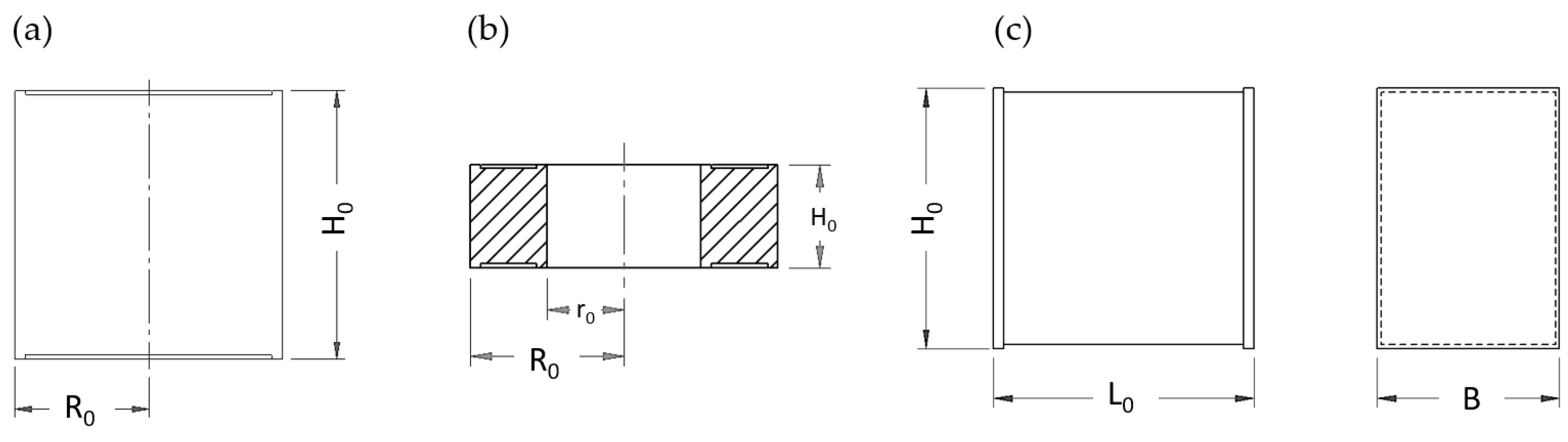
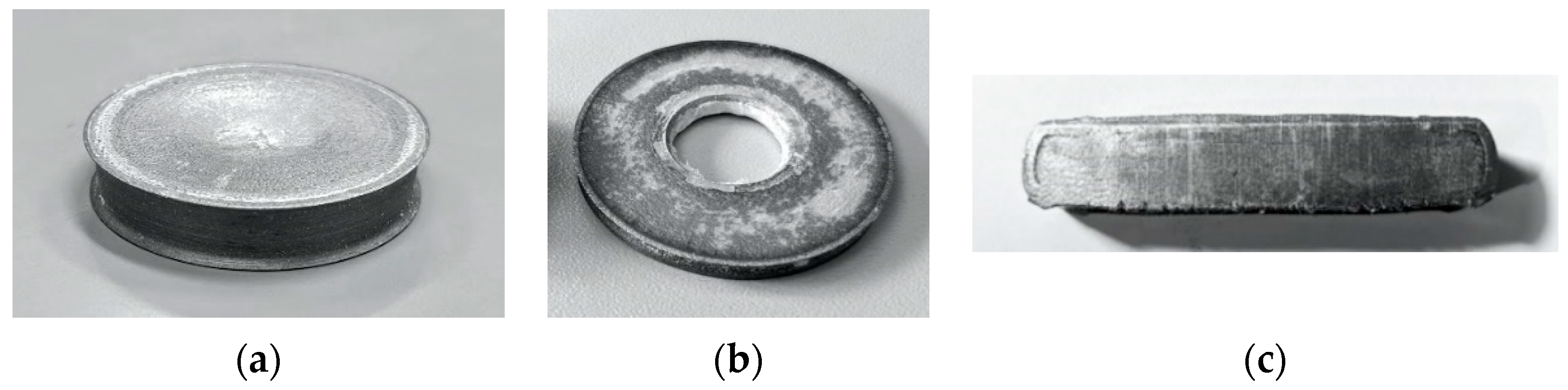
2.2.1. Cylinder Compression
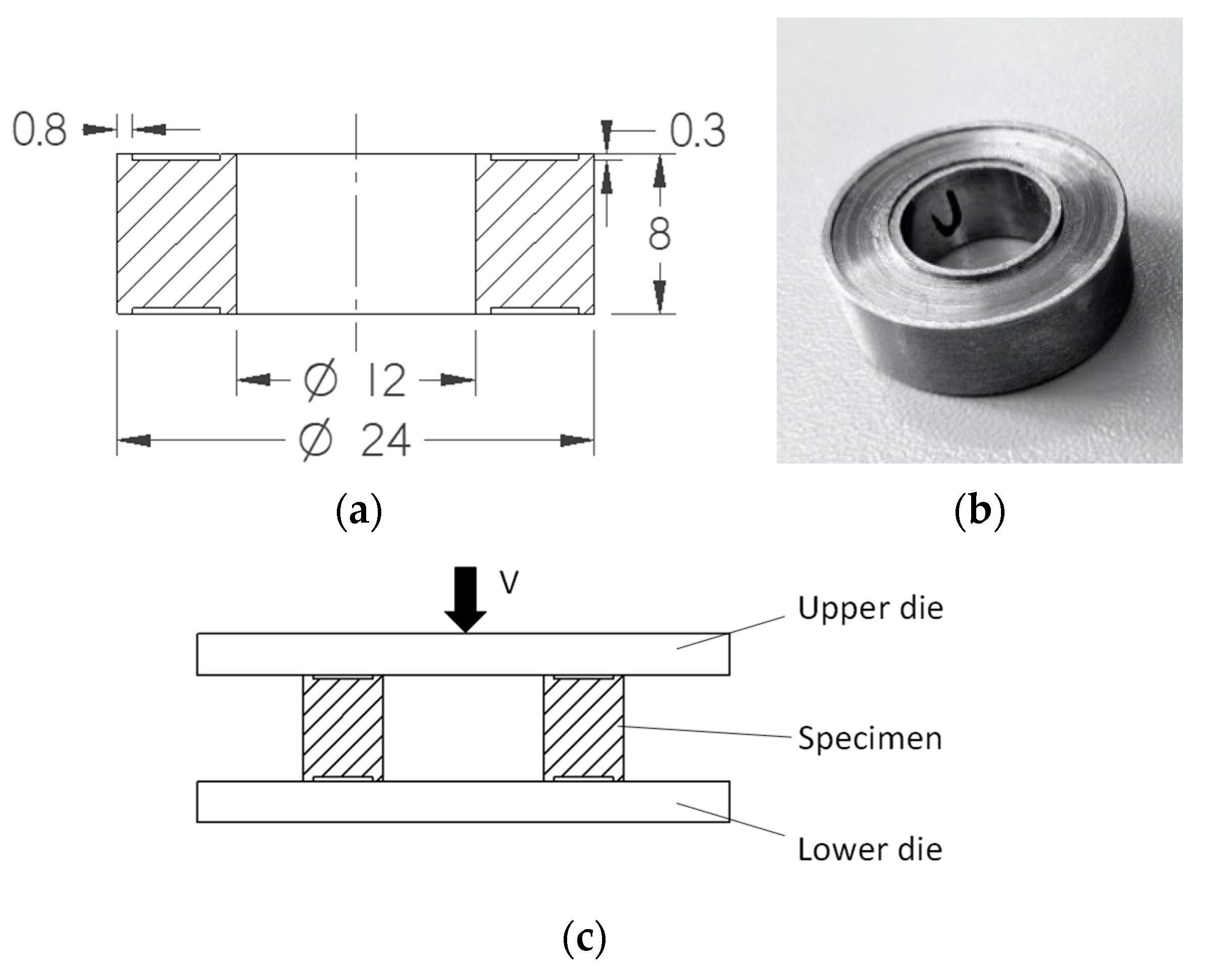
2.2.2. Ring Compression
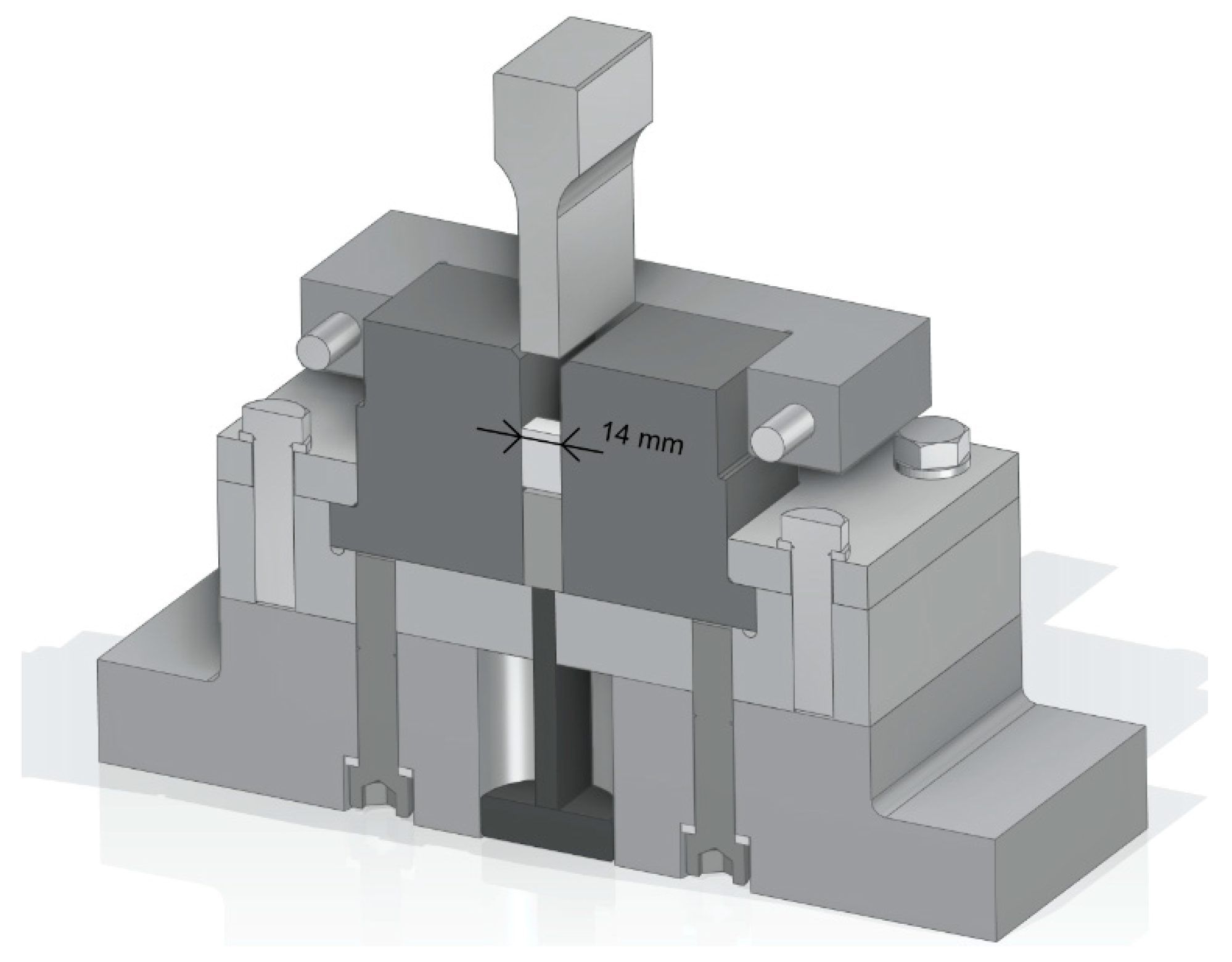
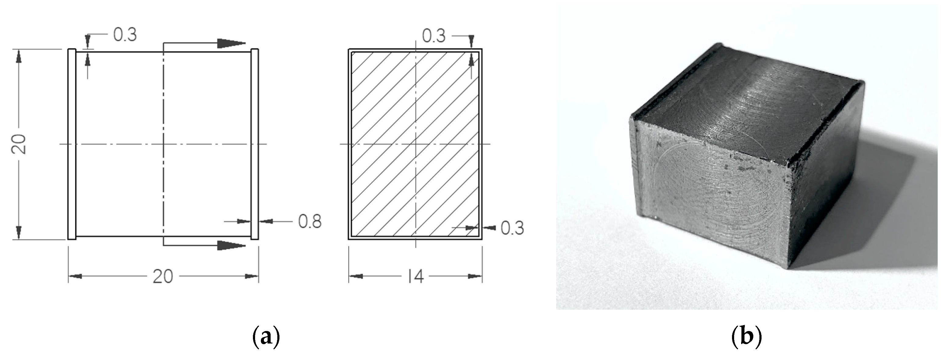
2.2.3. Plane Strain Compression
3. Experimental Design
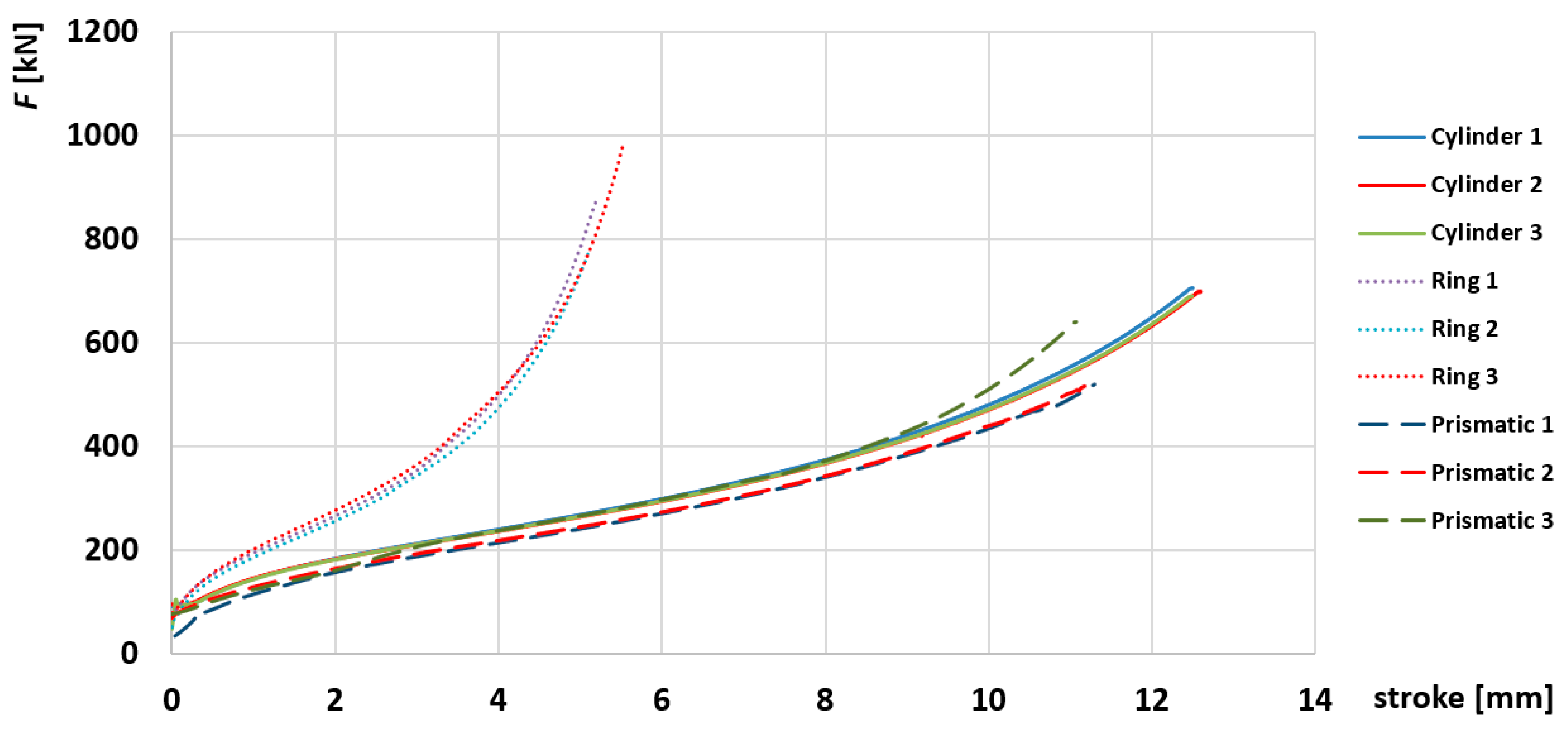
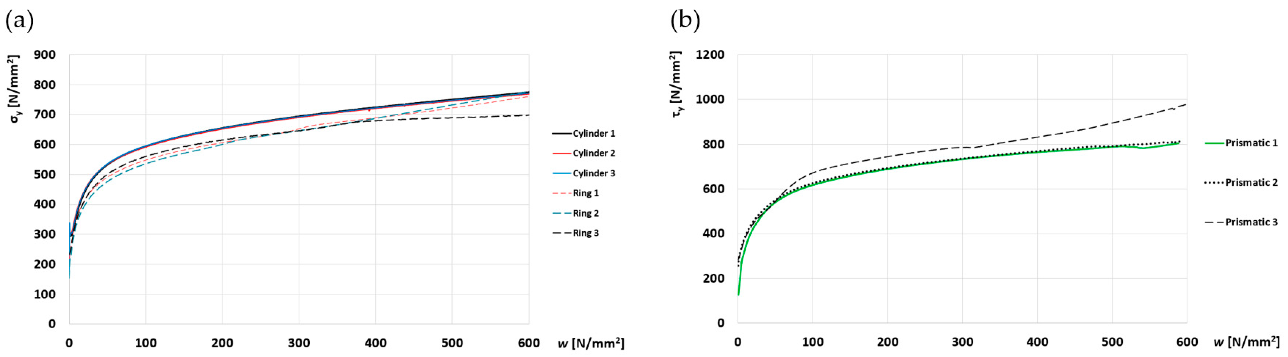
4. Experimental Results
5. Conclusions
Author Contributions
Funding
Data Availability Statement
Conflicts of Interest
Nomenclature
| h | dimensionless height |
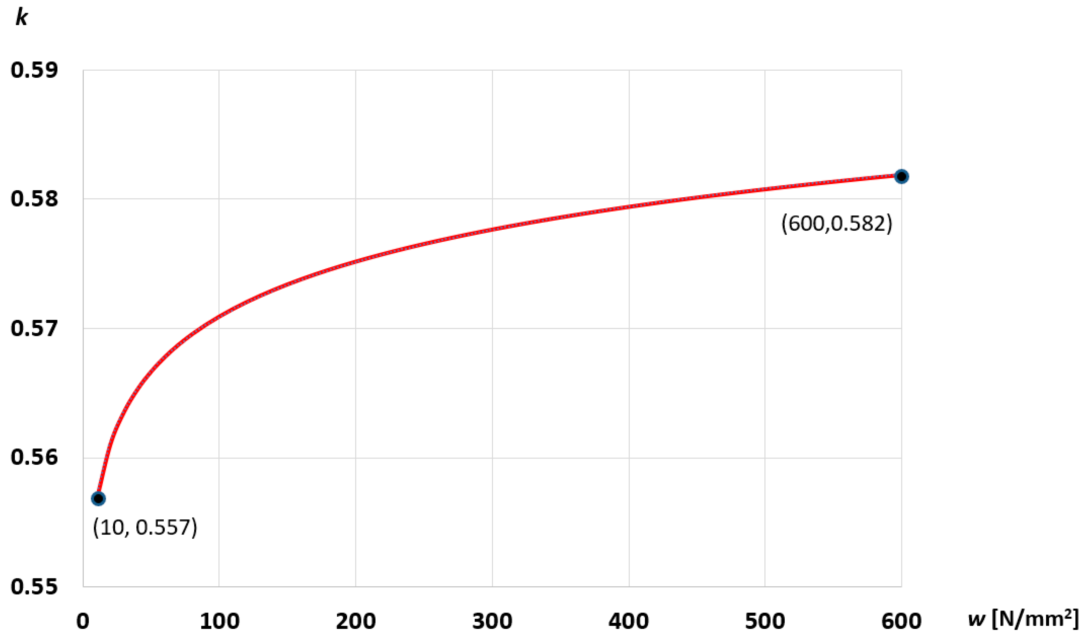
| k | ratio of the shear yield stress to the tensile yield stress |
| n | constitutive parameter |
| r | initial inner radius of ring specimens |
| s | current cross-sectional area of the ring specimens |
| t | time |
| ur, uz | radial and axial velocities |
| ux, uz | Cartesian velocity components |
| w | plastic work |
| B | width of strips |
| F | force required to deform specimens |
| H | current height of all specimens |
| H0 | initial height of all specimens |
| L | current length of strips |
| L0 | initial length of strips |
| R | current radius of cylindrical specimens |
| R0 | initial radius of cylindrical specimens and initial outer radius of ring specimens |
| V | velocity |
| dummy variable of integration | |
| , , | principal strain rates |
| , | strain rate components in x and z directions |
| , , | principal stresses |
| yield stress in tension | |
| axial stress | |
| shear yield stress |
Appendix A
References
- Nassiraei, H.; Rezadoost, P. Static Capacity of Tubular X-Joints Reinforced with Fiber Reinforced Polymer Subjected to Compressive Load. Eng. Struct. 2021, 236, 112041. [Google Scholar] [CrossRef]
- Jantarasricha, T.; Chongbunwatana, K.; Panich, S. Comparative Study of Fracture Criteria through Bona Fide Experimental–Numerical Examinations on AA2024-T3. Int. J. Adv. Manuf. Technol. 2022, 119, 7685–7710. [Google Scholar] [CrossRef]
- Zhong, B.; Qiang, X.; Yu, Z.; Hu, S.; Yang, H. Analysis and Prediction of Maximum Contact Stress and Depth by Ultrasonic Surface Rolling with Elastic–Plastic Theory. Int. J. Adv. Manuf. Technol. 2023, 124, 3225–3239. [Google Scholar] [CrossRef]
- Dong, W.; Zhao, A.; Tong, H.; Lin, Q.; Wang, Z. A Study on Variable Friction Model in Cold Forging Process with Zinc Phosphate Coating. Int. J. Adv. Manuf. Technol. 2023, 124, 3439–3451. [Google Scholar] [CrossRef]
- Zhu, X.-K.; Leis, B.N. Average Shear Stress Yield Criterion and Its Application to Plastic Collapse Analysis of Pipelines. Int. J. Press. Vessels Pip. 2006, 83, 663–671. [Google Scholar] [CrossRef]
- Barlat, F.; Richmond, O. Prediction of Tricomponent Plane Stress Yield Surfaces and Associated Flow and Failure Behavior of Strongly Textured f.c.c. Polycrystalline Sheets. Mater. Sci. Eng. 1987, 95, 15–29. [Google Scholar] [CrossRef]
- Taylor, G.I. Plastic Strain in Metals. J. Inst. Met. 1938, 62, 307–324. [Google Scholar]
- Hosford, W.F. A Generalized Isotropic Yield Criterion. J. Appl. Mech. 1972, 39, 607–609. [Google Scholar] [CrossRef]
- Billington, E.W. Generalized Isotropic Yield Criterion for Incompressible Materials. Acta Mech. 1988, 72, 1–20. [Google Scholar] [CrossRef]
- Reiss, W.; Pöhlandt, K. The Rastegaev Upset Test-A Method To Compress Large Material Volumes Homogeneously. Exp. Tech. 1986, 10, 20–24. [Google Scholar] [CrossRef]
- Alexandrov, S.; Vilotic, D.; Konjovic, Z.; Vilotic, M. An Improved Experimental Method for Determining the Workability Diagram. Exp. Mech. 2013, 53, 699–711. [Google Scholar] [CrossRef]
- Sliwa, R. A Test Determining the Ability of Different Materials to Undergo Simultaneous Plastic Deformation to Produce Metal Composites. Mat. Sci. Eng. A-Struct. 1991, 135, 259–265. [Google Scholar] [CrossRef]
- Han, H. The Validity of Mathematical Models Evaluated by Two-Specimen Method under the Unknown Coefficient of Friction and Flow Stress. J. Mater. Process. Technol. 2002, 122, 386–396. [Google Scholar] [CrossRef]
- Srinivasan, N.; Kain, V.; Samajdar, I.; Krishna, K.V.M.; Sivaprasad, P.V. Plane Strain Compression Testing of Sanicro 28 by Channel-Die Compression Test: A Direct Microstructural Observation. Mater. Today Proc. 2017, 4, 9888–9892. [Google Scholar] [CrossRef]
- Liang, Y.; Jiang, S.; Zhang, Y.; Zhao, C. Effect of Plane Strain Compression and Subsequent Recrystallization Annealing on Microstructures and Phase Transformation of NiTiFe Shape Memory Alloy. J. Mater. Eng. Perform. 2018, 27, 4514–4524. [Google Scholar] [CrossRef]
- Sae-Eaw, N.; Aue-U-Lan, Y. Mechanical Property Determination for Combined Sheet and Bulk Metal Forming Process by Plane Strain Compression Test. Mater. Today Proc. 2018, 5, 9376–9383. [Google Scholar] [CrossRef]
- Chermette, C.; Unruh, K.; Peshekhodov, I.; Chottin, J.; Balan, T. A New Analytical Method for Determination of the Flow Curve for High-Strength Sheet Steels Using the Plane Strain Compression Test. Int. J. Mater. Form. 2020, 13, 269–292. [Google Scholar] [CrossRef]
- Saalari, M. Comparison of Texture Evolution in Low Carbon Steel Fabricated by Plane Strain and Multi-Directional Forging of the Martensite Starting Structure. Int. J. Microstruct. Mater. Prop. 2019, 14, 524. [Google Scholar] [CrossRef]
- Jiang, S.; Yu, J.; Zhang, Y.; Xing, X. Mechanically-Induced Martensite Transformation of NiTiFe Shape Memory Alloy Subjected to Plane Strain Compression. Trans. Nonferrous Met. Soc. China 2020, 30, 1325–1334. [Google Scholar] [CrossRef]
- Guerza-Soualah, F.; Azzeddine, H.; Baudin, T.; Helbert, A.-L.; Brisset, F.; Bradai, D. Microstructural and Textural Investigation of an Mg–Dy Alloy after Hot Plane Strain Compression. J. Magnes. Alloys 2020, 8, 1198–1207. [Google Scholar] [CrossRef]
- Lagzian, Y.; Rezaee-Bazzaz, A. Texture Evolution of Commercially Pure Copper Processed by Multiple Compressions in a Channel Die. Eng. Res. Express 2020, 2, 015002. [Google Scholar] [CrossRef]
- Wen, D.; Kong, B.; Wang, S.; Zong, Y. Effect of Hydrogen on the Flow Behavior of a TiAl Based Alloy during Plane Strain Compression at Elevated Temperature. Int. J. Hydrogen Energy 2020, 45, 4897–4909. [Google Scholar] [CrossRef]
- Ghosh, A.; Roy, A.; Ghosh, A.; Ghosh, M. Influence of Temperature on Microstructure, Crystallographic Texture and Mechanical Properties of EN AW 6016 Alloy during Plane Strain Compression. Mater. Today Commun. 2021, 26, 101808. [Google Scholar] [CrossRef]
- Tamanna, N.; Slater, C.; Davis, C. Effect of Sample Geometry on Strain Uniformity and Double Hit Compression Tests for Softening Kinetics Determination. Steel Res. Int. 2022, 93, 2200157. [Google Scholar] [CrossRef]
- Diot, S.; Guines, D.; Gavrus, A.; Ragneau, E. Minimization of Friction Influence on the Evaluation of Rheological Parameters From Compression Test: Application to a Forging Steel Behavior Identification. J. Eng. Mater. Technol. 2009, 131, 011001. [Google Scholar] [CrossRef] [Green Version]
- Christiansen, P.; Martins, P.A.F.; Bay, N. Friction Compensation in the Upsetting of Cylindrical Test Specimens. Exp. Mech. 2016, 56, 1271–1279. [Google Scholar] [CrossRef] [Green Version]
- Chen, J.; Guan, Z.; Ma, P.; Li, Z.; Gao, D. Experimental Extrapolation of Hardening Curve for Cylindrical Specimens via Pre-Torsion Tension Tests. J. Strain Anal. Eng. Des. 2020, 55, 20–30. [Google Scholar] [CrossRef]
- Hu, G.; Zhang, K.; Huang, S.; Ju, J.-W.W. Yield Surfaces and Plastic Flow of 45 Steel under Tension-Torsion Loading Paths. Acta Mech. 2012, 25, 348–360. [Google Scholar] [CrossRef]
- Semka, E.V.; Artemov, M.A.; Babkina, Y.N.; Baranovskii, E.S.; Shashkin, A.I. Mathematical Modeling of Rotating Disk States. J. Phys. Conf. Ser. 2020, 1479, 012122. [Google Scholar] [CrossRef]
- Male, A.T.; Cockcroft, M.G. A Method for the Determination of the Coefficient of Friction of Metals under Conditions of Bulk Plastic Deformation. J. Inst. Met. 1964, 93, 38–45. [Google Scholar] [CrossRef]
- Vilotic, M.; Dacevic, N.; Milutinovic, M.; Movrin, D.; Sidjanin, L. New Severe Plastic Deformation Method for 316L Medical Grade Steel Processing. Acta Tech. Corviniensis Bull. Eng. 2020, 13, 13–16. [Google Scholar]


| Mass. % | C | Si | Mn | S | Cr | P | Al | Cu | Mo | Ni |
|---|---|---|---|---|---|---|---|---|---|---|
| C15E | 0.17 | 0.25 | 0.516 | 0.019 | 0.017 | 0.015 | 0.022 | 0.140 | 0.045 | 0.214 |
Disclaimer/Publisher’s Note: The statements, opinions and data contained in all publications are solely those of the individual author(s) and contributor(s) and not of MDPI and/or the editor(s). MDPI and/or the editor(s) disclaim responsibility for any injury to people or property resulting from any ideas, methods, instructions or products referred to in the content. |
© 2023 by the authors. Licensee MDPI, Basel, Switzerland. This article is an open access article distributed under the terms and conditions of the Creative Commons Attribution (CC BY) license (https://creativecommons.org/licenses/by/4.0/).
Share and Cite
Alexandrov, S.; Vilotic, M.; Dacevic, N.; Li, Y. Identification of Hosford’s Yield Criterion Using Compression Tests. Metals 2023, 13, 471. https://doi.org/10.3390/met13030471
Alexandrov S, Vilotic M, Dacevic N, Li Y. Identification of Hosford’s Yield Criterion Using Compression Tests. Metals. 2023; 13(3):471. https://doi.org/10.3390/met13030471
Chicago/Turabian StyleAlexandrov, Sergei, Marko Vilotic, Nemanja Dacevic, and Yong Li. 2023. "Identification of Hosford’s Yield Criterion Using Compression Tests" Metals 13, no. 3: 471. https://doi.org/10.3390/met13030471