Article

Features of Permanent Joints of Titanium (α+β)-Alloys Obtained by Friction Stir Welding Using a Nickel Superalloy Tool

Institute of Strength Physics and Materials Science, Siberian Branch of Russian Academy of Sciences, 634055 Tomsk, Russia
*
Author to whom correspondence should be addressed.
Metals 2023, 13(2), 222; https://doi.org/10.3390/met13020222
Submission received: 31 December 2022 / Revised: 19 January 2023 / Accepted: 19 January 2023 / Published: 24 January 2023
(This article belongs to the Special Issue Advanced Welding Technology in Metals II)

Abstract

:
Titanium alloys are widely used in industry, especially (α+β)-alloys, among which Ti-6Al-4V alloy is the most popular one. Another common alloy that often appears in patents for titanium products is Ti-4Al-3Mo-1V. Here, we investigate welded joints of (α+β)-alloy Ti-4Al-3Mo-1V obtained by friction stir welding (FSW) using a working tool made of nickel-based heat-resistant alloy ZhS6U. In addition, welded joints of Ti-6Al-4V and Ti-4Al-3Mo-1V alloys with similar mechanical characteristics were considered. Mechanical tests showed that the obtained joints had a tensile strength greater than that of the base metal. This result was achieved in the welding mode where the axial load was varied during the welding process. X-ray diffraction analysis revealed a change in the phase structure of the welded joint.

1. Introduction

Modern engineering tasks require constant search for materials that can withstand aggressive environments during operation, meeting high requirements for strength, resistance to oxidation, fatigue, fracture, and creep. These materials include alloy steels and superalloys that present heat-resistant materials based on Fe, Ni, and Co. They occupy a major share of use in structural or functionally critical parts for applications ranging from cryogenic to high-temperature. One of the main factors that limits the use of these alloys for space-based structures is their much higher density, which leads to increased weight of structures. This aroused interest in the development of materials with lower density, and titanium alloys became the obvious choice because of their high specific strength, fatigue resistance, and excellent corrosion resistance [1,2,3]. Therefore, they have been widely applied in aerospace, power, chemical, and shipbuilding industries and in medicine [4,5,6].
In their turn, titanium alloys are divided into several types: titanium α-alloys, (α+β)-alloys, and β-alloys [7,8]. The first group includes commercially pure titanium and alloys with a small amount of α-phase stabilizer, which is usually aluminum. These alloys have more applications in the chemical industry and medicine. In (α+β)-alloys, there are small amounts of both α-phase and β-phase stabilizers. These alloys have more applications in the aviation and space industries. The last group is β-alloys, containing up to 30% of β-phase stabilizers, such as Ti-30V. They are also used in the space industry. The α-phase of titanium alloys is characterized by an HCP-type crystal lattice and the β-phase has a BCC-type crystal lattice [9,10]. Thus, titanium (α+β)-alloys have become the most widespread. Unlike α-alloys and α′-alloys with a tensile strength of 300–600 MPa, these alloys have a tensile strength of 700–1000 MPa [11]. In some cases, the tensile strength can exceed 1000 MPa, e.g., Ti-4Al-3Mo-1V after quenching and artificial aging [12]. In this case, in contrast to the titanium β-alloys, they are less brittle. The microstructures in these titanium alloys can be adapted to produce different α-phase titanium morphologies, such as laminar, duplex, and globular, based on thermomechanical treatment and heat treatment [13]. However, obtaining welded joints of titanium alloys is complicated by a number of problems, such as the low thermal conductivity of titanium, which leads to appreciable overheating of heat-affected zones during welding, growth of grain size within them, and generation of high residual stresses [14]. In addition, conventional fusion welding, such as laser welding, electron-beam welding, and welding in shielding gases, leads to the formation of porosity, cracking, and reduced the corrosion resistance of the weld material. Therefore, the strength characteristics of titanium-alloy welded joints can be enhanced using either surface plastic deformation methods or heat treatment that requires the use of expensive and bulky equipment [1,15,16,17].
Currently, solid-phase welding methods such as friction stir welding (FSW) are a focus of intense research. In practice, this welding is mainly used for joining aluminum alloys employed in the aerospace, transport, and power industries [18,19,20]. Friction stir welding reduces the factors that induce defects in the welded joint and are associated with heating the welded material to its melting point [21]. In addition, FSW of titanium alloys is being actively studied by ESA and NASA for welding the fuel tanks of upper stages of launch vehicles [22]. ESA, in a joint effort with TWI and Airbus, have investigated the FSW of Ti 15V-3Cr-3Al-3Sn and Ti-6Al-4V titanium alloys.
Careful selection of friction stir welding process parameters is crucial to achieve the desired microstructure and reliable welds in large welded components for space applications [23]. Optimization of welding process parameters for titanium alloys involves the study of the influence of each parameter, mainly welding speed and tool rotation frequency, on the strength properties of the resulting welded joints [24,25,26]. The weld structure formation as a result of thermomechanical influence of welding has also been intensively investigated [27,28]. It has been found that the thermomechanical effects of welding give rise to synchronized processes of recovery and dynamic recrystallization, thus leading to the redistribution of α- and β-phases, which makes a significant contribution to the strength properties of the obtained welded joint [16,29,30]. At the same time, much less attention has been given to the influence of the axial force.
In addition to optimizing the process parameters in the FSW of titanium alloys, there is a problem of rapid wear of the working tool due to various disadvantages, the main one being fast wear. For example, tungsten carbide tools, despite their high thermal resistance, are also brittle and wear too quickly [31]. Tungsten–rhenium tool compounds have greater resistance to wear, but their production is costly and technically challenging [32]. Worth mentioning are tools made from polycrystalline cubic boron nitride, which shows excellent performance in FSW steels [33]. However, titanium alloys are quite reactive with boron and nitrogen, which results in strong embrittlement of the weld seam [34]. The situation is complicated by the fact that most authors give little attention to the problem of tool wear [35].
Promising in this respect are working tools made of nickel-based heat-resistant alloys. As a rule, these alloys are used for components working at temperatures of 900–1000 °C [36]. Welding tools made of heat-resistant alloys have already been used in friction stir processing (FSP) of titanium alloys [37] and FSW of titanium α- and α′-alloys [38,39,40] and FSW steels [41].
Based on the foregoing, the purpose of this work is to study the permanent joints of titanium (α+β)-alloys by using the example of the alloy Ti-4Al-3Mo-1V obtained by friction stir welding, namely, the study of the formation of joint structure together with the mechanical properties of the connection, with the tool made of heat-resistant alloys based on nickel ZhS6U. Consideration is given for the first time to the layer of intermetallic compounds in the Ti-4Al-3Mo-1V alloy joint welded by this tool. Additionally, for the first time, the permanent joints of homogeneous Ti-6Al-4V and Ti-4Al-3Mo-1V titanium alloys are considered.

2. Experimental Procedure

2.1. Materials and Experimental Setup

Welding was performed using a protective atmosphere of argon, which was fed through a special nozzle directly into the area of the welded joint, as shown in Figure 1a. The sheets to be welded were laid on an AISI 304 stainless steel plate, which was used as a substrate and provided partial heat dissipation during welding. The tool was axially loaded into the titanium sheets at a certain rotational speed and then moved forward along a straight line. Friction between the tool and the workpiece resulted in heating, plasticizing, and stirring of the material. FSW was carried out at a constant axial load, which is a given parameter to maintain the flow of metal, both during the tool plunge stage and the welding process. The FSW tool began to move immediately after the tool shoulders came into contact with the workpiece surface.
The angle of inclination of the tool was 1.5 degrees. The tool was connected to a liquid cooling system in order to decrease tool wear and consequently increase its life. The FSW working tool had the following geometry: the diameter of the tool shoulders was 20 mm, the diameter of the pin at the height was 3 mm, and the height of the pin was 2.3 mm. The pin height was deliberately slightly smaller than the workpiece thickness of the sheet to avoid welding the titanium alloy sheets to the substrate sheet. The composition of the tool alloy, ZhS6U (K465), from which the working tool of FSW titanium alloys was made, is shown in Table 1.
The welding workpieces were made from rolled sheets of titanium alloy Ti-4Al-3Mo-1V. Their thickness was 2.5 mm. The grade composition of the alloy is shown in Table 2. The alloy was in as-received state and was not quenched. Therefore, its strength averaged about 790 MPa. The workpieces were air purged after each pass to reduce the thermal stress.
Workpieces were also made of rolled sheets of the titanium alloy Ti-6Al-4V with the same thickness of 2.5 mm. The grade composition of the alloy is shown in Table 3. Unlike the previous samples, these sheets were quenched in the as-received state, owing to which their strength was about 1010 MPa. The strength characteristics of Ti-4Al-3Mo-1V and Ti-6Al-4V alloys in the as-received state were determined in tensile tests. The obtained values of the ultimate strength of the alloys were different from their grade-ultimate strength [42] within the permissible error.
Table 4 shows the modes of FSW in which the welded joints were obtained. In Table 4, the following parameters are conventionally designated: tool rotation speed—ω, axial force on the tool at penetration—Fp, axial force on the tool at welding—Fw, and welding speed—V. Under numbers from 1 to 4, the parameters for which the welding of titanium alloy Ti-4Al-3Mo-1V sheet was performed are shown. Numbers 5 and 6 show the parameters at which the alloy Ti-4Al-3Mo-1V sheet was welded with the alloy Ti-6Al-4V sheet. It can be noticed that modes 1 and 2 differ only in numbers. This was carried out to form a thin layer of adhered titanium on the tool for its better adhesion with the welded material in further welding.

2.2. Investigative Techniques

The samples were cut-out perpendicularly to the welding direction in order to study the structure of the resulting joints. Afterward, they were ground and polished with diamond paste. Then, the cross-section samples were etched in a reagent of 30 mL C3H8O3, 10 mL HNO3, and 10 mL HF for 30–35 s.
The macro- and microstructure of the welded joints were examined by metallography using an Altami Met 1S optical microscope (Altami, Saint Petersburg, Russia). Images of fracture surfaces after mechanical tests were obtained on an Apreo 2 S high-resolution scanning electron microscope with field emission (FEG SEM) (Thermo Fisher Scientific, Waltham, MA, USA) equipped with an Octane Elect Super energy dispersive X-ray detector (EDAX, Mahwah, NJ, USA). X-ray structural analysis of the as-received and welded Ti-4Al-3Mo-1V alloy was performed on a DRON-7 X-ray diffractometer (Burevestnik, Saint Petersburg, Russia). Data were taken at 36 kV and 22 mA using CoKα radiation with a wavelength of 1.7902 Å. The scanning range of 2θ angles was 15–102°, the angle step was 0.05°, and the exposure time was 40 s. Peak identification and diffractometer data processing were performed using Crystal Impact’s “Match!” software (version 3.9). The relative percentage intensity of α- or β-phases, denoted R(x), was calculated by using Formula (1) [43].
R ( x ) = ( I ( x ) / I ( A ) ) × 100
where I(x) is the reflection intensity corresponding to the “x” phase, and I ( A ) is the sum of all analyzed reflection intensities.
Microhardness measurements were carried out on an AFFRI DM8 microhardness tester (Affairs, Varese, Italy) under an indentation load of 100 kN and a dwell time of 10 s. The measurements were performed on the samples for metallographic studies in the vertical and horizontal directions with a step of 1 mm. The obtained welded joints were tested for strength on a UTS 110M-100 testing machine (Testsystems, Ivanovo, Russia) at room temperature. Strength tests were conducted in accordance with the procedure described in [44]. Fatigue tests were conducted on the universal machine BISS UTM at 100 kN. Variable tensile load from maximum tensile stress σmax to minimum σmin was applied along the specimen axis or perpendicular to the weld seam. The frequency of loading cycles was 30 Hz. For all mechanical tests, flat specimens were made by cutting across the welded joint with the location of the weld in the center of the working part of the specimen. The dimensions of the working part of the samples were 25 × 12 × 2.5 mm. The cutting pattern of specimens for mechanical and metallographic tests is shown in Figure 1b.

3. Results and Discussion

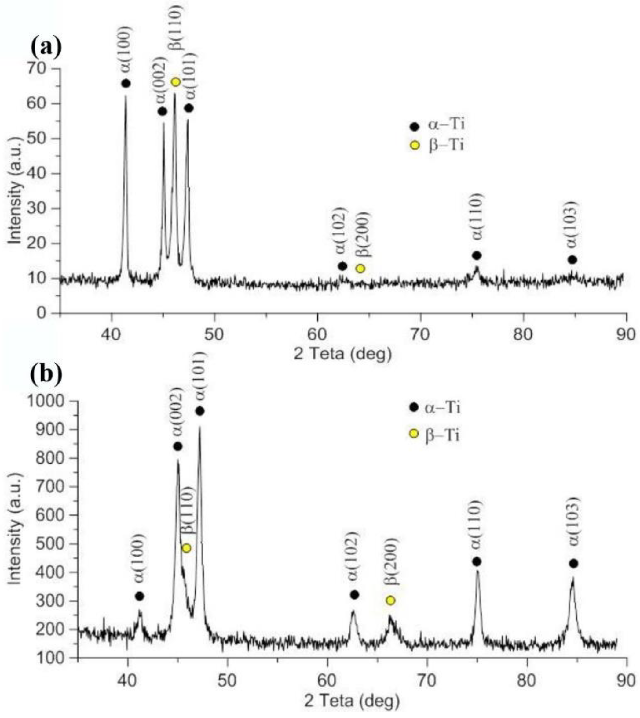
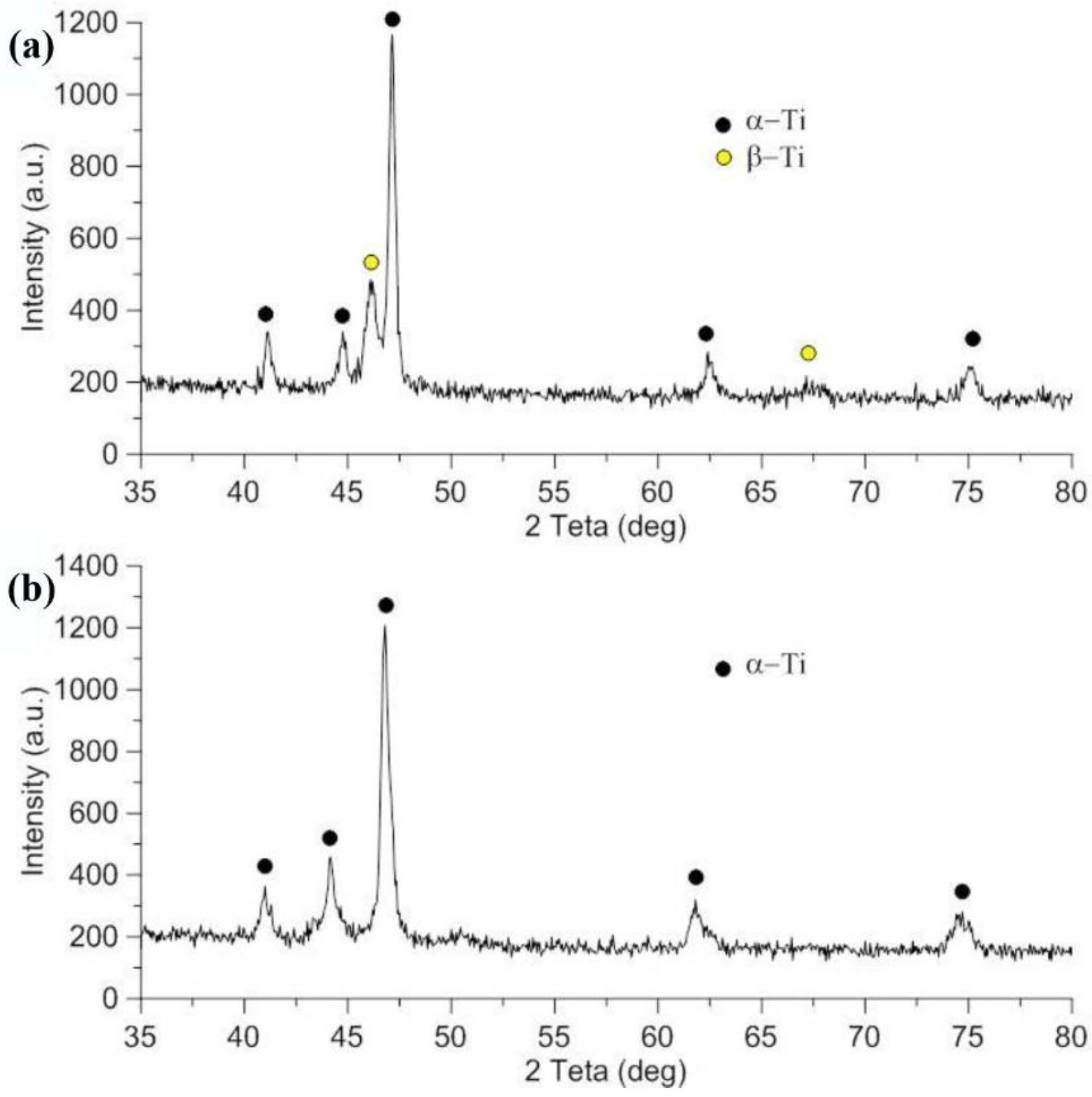
Phase composition of as-received Ti-6Al-4V and Ti-4Al-3Mo-1V alloys was analyzed by X-ray diffraction (XRD). The XRD spectra illustrated in Figure 2 verified that base alloys consisted of α- and β-phases. It can be seen that the as-received Ti-6Al-4V and Ti-4Al-3Mo-1V alloys are composed of 74 vol.% α-Ti + 26 vol.% β-Ti (Figure 2a) and 78 vol.% α-Ti + 22 vol.% β-Ti (Figure 2b), respectively. In the case of Ti-4Al-3Mo-1V, the (110) β reflection is located quite close to the (110) α reflection (Figure 2b) as compared with Ti-6Al-4V (Figure 2a). Apparently, the chemical elements stabilizing the β-phase and dissolved in its lattice are the reason for the increased volume fraction of β-phase in the alloy Ti-4Al-3Mo-1V compared with the alloy Ti-6Al-4V.
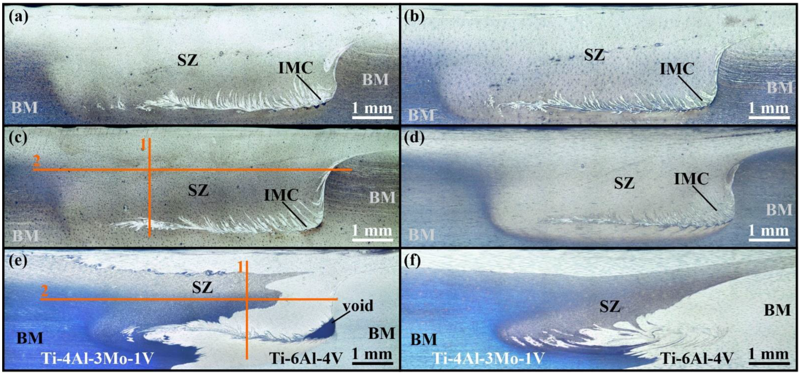
Metallographic images of cross-sectional weld samples are shown in Figure 3. The joints have a typical macrostructure obtained by FSW of titanium alloys, but exhibit some specific features due to the low thermal conductivity and high strength of titanium alloys [45]. Thus, there are three typical zones for FSW joints of titanium alloys observed in the figures: 1—stir zone (SZ), 2—heat-affected zone (HAZ), and 3—base metal (BM). The stir zone is located in the area of direct contact with the tool and consists of recrystallized grains of the alloy. The heat-affected zone is located along the edges of the stir zone and is quite narrow [46,47,48]. Additionally, the thermomechanical-affected zone (TMAZ), which normally occurs during the FSW of aluminum alloys, is difficult to detect for titanium (α+β)-alloys [49,50,51]. The macrostructure of the joint obtained by the tool without adhered titanium is presented in Figure 3a to show the amount of the material adhered to the tool. There are areas of intermetallic components (IMC) in this joint under which discontinuities can be seen.
The macrostructure of specimen-2 obtained at the same parameters as specimen-1 is shown in Figure 3b. In this specimen, considerably fewer intermetallic components are observed, which are typical in the FSW of titanium alloys with nickel tools [39,52]. In addition, there are almost no defects such as discontinuities observed in the first sample. This indicates a positive effect of adhered titanium on the welding tool on the resulting joints. The depth of the stir zone increased with the increasing axial force on the tool. This can be seen in Figure 3c showing the macrostructure of sample-3. A tunnel defect appeared in the lower part of the stir zone on the advancing side of the weld, under the layer of intermetallic components. The size of the stir zone increased with the subsequent increase in the axial force, while the heat-affected zone also increased, which may indicate overheating of the welded material. This can be seen from the macrostructure of sample-4 shown in Figure 3d. The tunnel defect under the intermetallic layer disappeared.
Figure 3e shows sample-5 cut from the FSW joint between Ti-4Al-3Mo-1V and Ti-6Al-4V alloys. Here, the lighter-colored Ti-6Al-4V alloy is on the advancing side, and the darker-colored Ti-4Al-3Mo-1V alloy is on the retreating side of the weld. The mutual penetration of these alloys is observed in the SZ, and the layer of the intermetallic components of titanium alloy and tool material is almost entirely in the SZ of Ti-6Al-4V alloy. The same area exhibits a tunnel defect. Sample-6 was obtained from the same alloys welded by increasing the axial load. Its metallographic image is shown in Figure 3f. The tunnel defect disappeared and the alloys penetrated more deeply into each other, indicating better adhesion between the alloys during friction stir welding than the previous joint. 
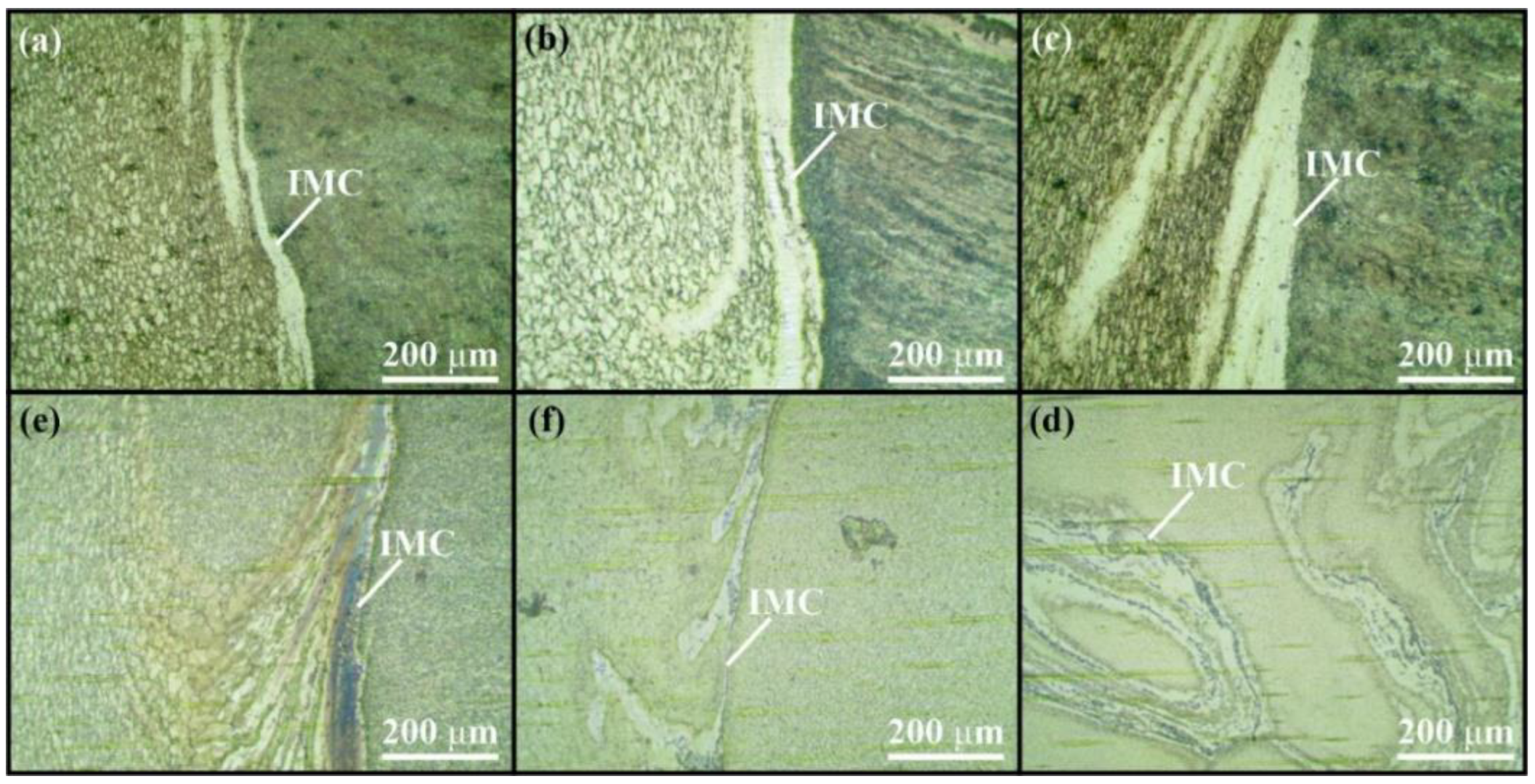
Figure 4 shows the microstructures of the base metal zones, SZ, areas of transition from the SZ to the HAZ, and BM on the advancing side of the joint, which contains a layer of intermetallic components (IMC) of the titanium alloy and tool material, together with the lower part of the joint with the weld-root failure. Figure 4a–d illustrate the microstructure of Ti-4Al-3Mo-1V joint samples.
Figure 4e shows the microstructure of dissimilar Ti-6Al-4V/Ti-4Al-3Mo-1V joint sample-5. In the SZ, there is a place of transition from Ti-4Al-3Mo-1V alloy (darker area) to Ti-6Al-4V alloy (lighter area). Figure 4f shows the microstructure of sample-6. One can see intermetallic components on the side of Ti-6Al-4V alloy. Their distribution pattern indicates turbulent adhesion of the material at the lower part of the joint in both sample-5 and sample-6. The mutual penetration of Ti-6Al-4V and Ti-4Al-3Mo-1V alloys is not observed.
The results of mechanical tensile tests of Ti-4Al-3Mo-1V joint samples are given in Table 5. The strength of the samples obtained in all modes exceeds 90% of the ultimate strength of the base material. The most durable welds were obtained in mode-2. In the subsequent modes, the weld strength decreased. This could be due to material overheating at higher axial loads on the tool.
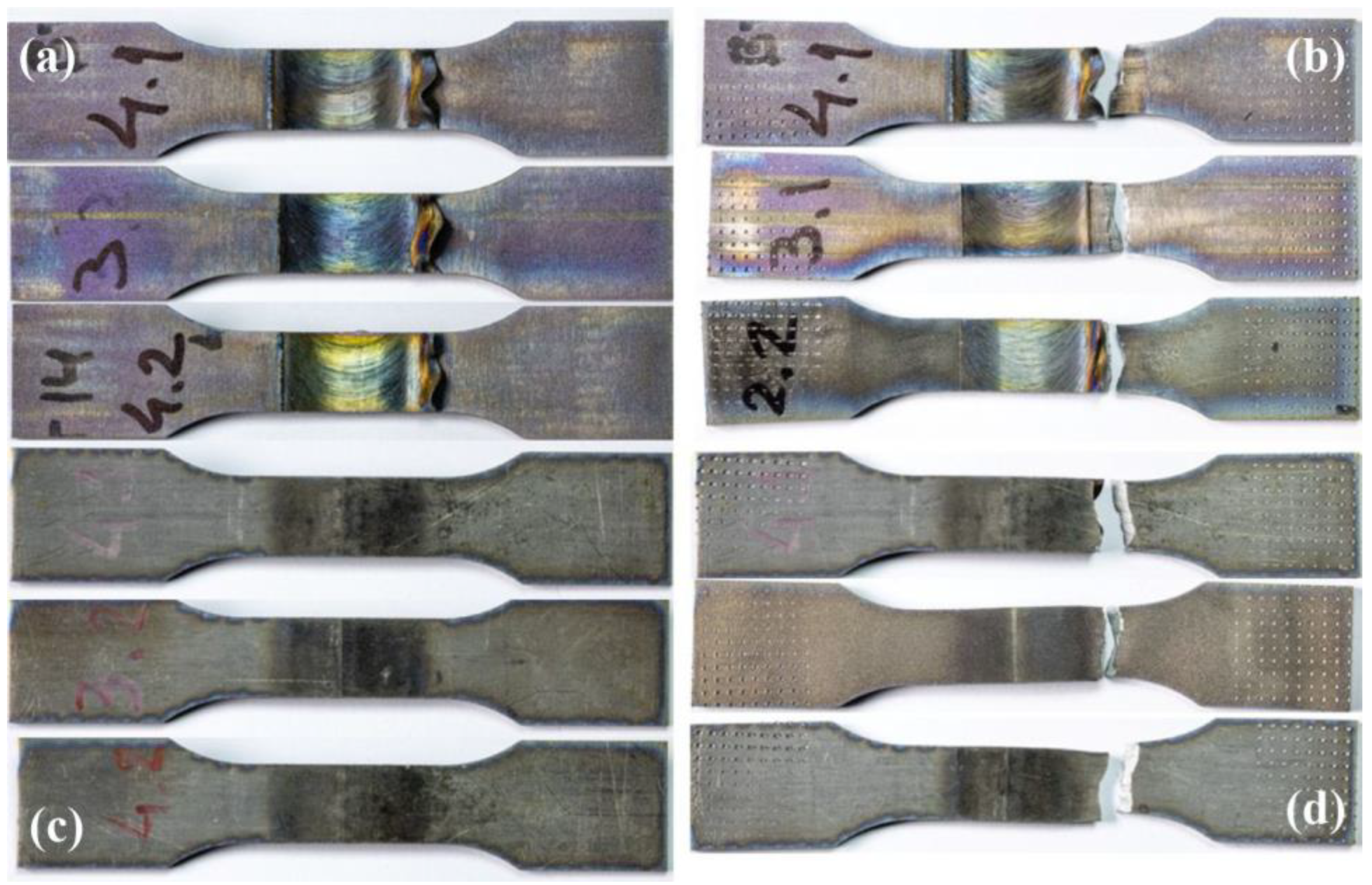
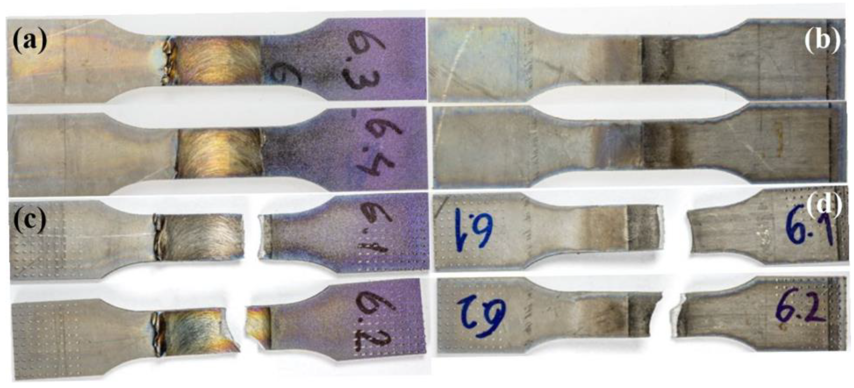
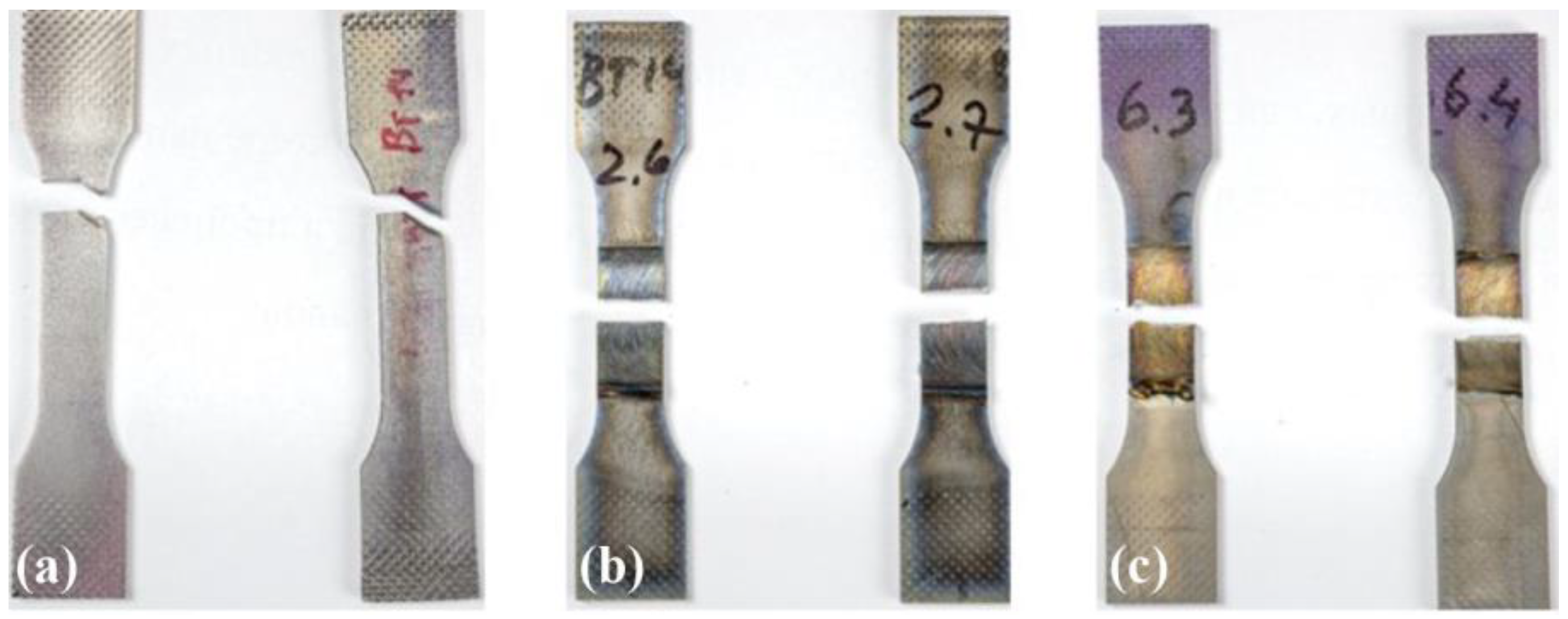
The view of Ti-4Al-3Mo-1V alloy joint specimens before (a, c) and after (b, d) mechanical tensile tests is shown in Figure 5. The specimens fractured mainly in the heat-affected zone, which is usually characterized by higher brittleness. Another factor determining the fracture location could be the sharp transition between the intermetallic layer located at the boundary of the SZ and HAZ.
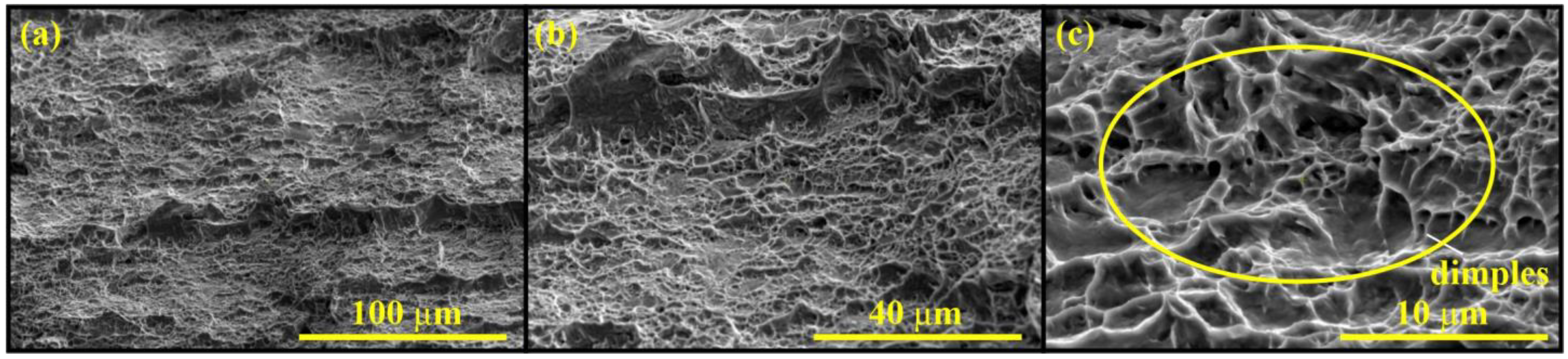
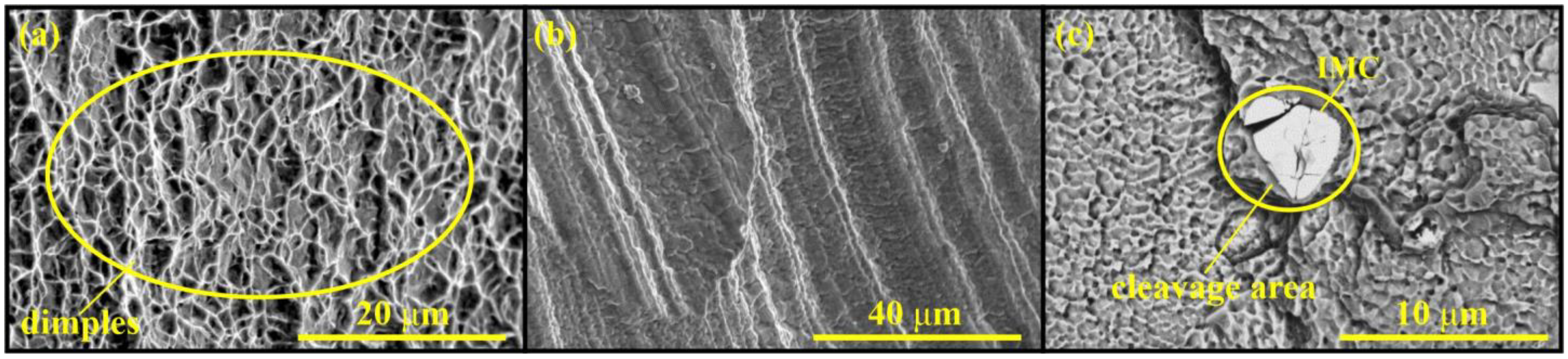
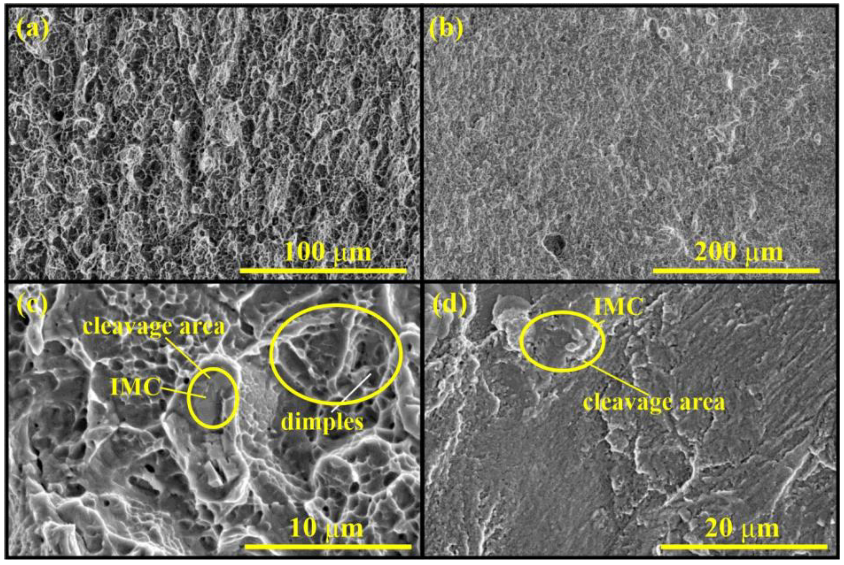
Figure 6 shows the fracture surface of the Ti-4Al-3Mo-1V joint specimens in the HAZ. It can be seen that the titanium alloy material experienced predominantly ductile fracture during static tensile tests, which is characteristic of titanium alloys, as evidenced by dimpled fractures. Dimples are separated by sufficiently large and branched ductile bridges, and there are small zones of stretched material. Thus, the fracture occurred in a region with a large number of low-dimensional and deformed structural elements, which corresponds to the partially fragmented and highly deformed grains of the weld HAZ.
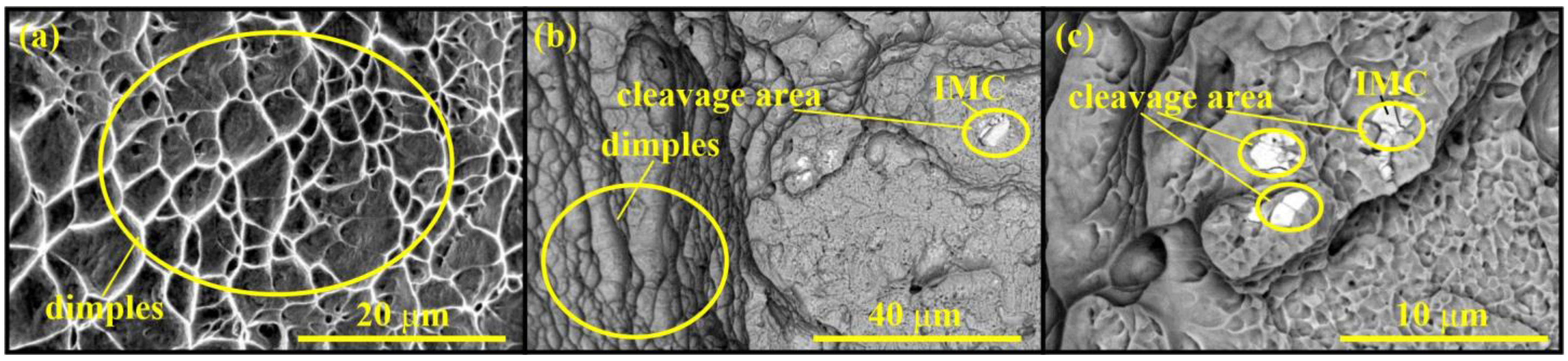
Figure 7 shows the fracture surface of the joint specimens in the SZ. The fracture structure in these areas changed due to the presence of the tool material fragments stirred into the weld zone. The bright areas in the backscattered electron images indicate that the fracture passed through the intermetallic layer between the titanium alloy and tool material. The images of these areas obtained in the secondary electron mode did not show a dimpled fracture structure, but showed signs of cleavage, indicating brittle fracture in areas of the intermetallic component layer during fracture.
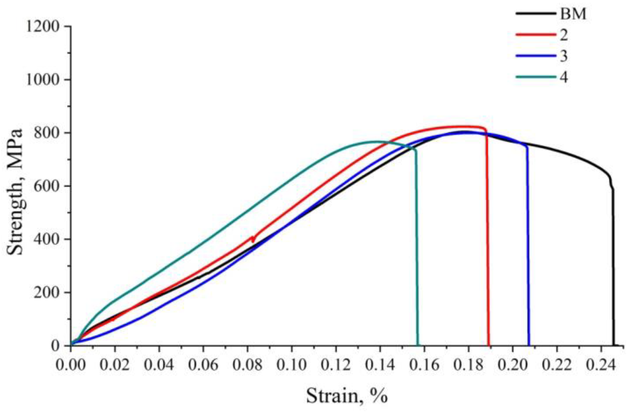
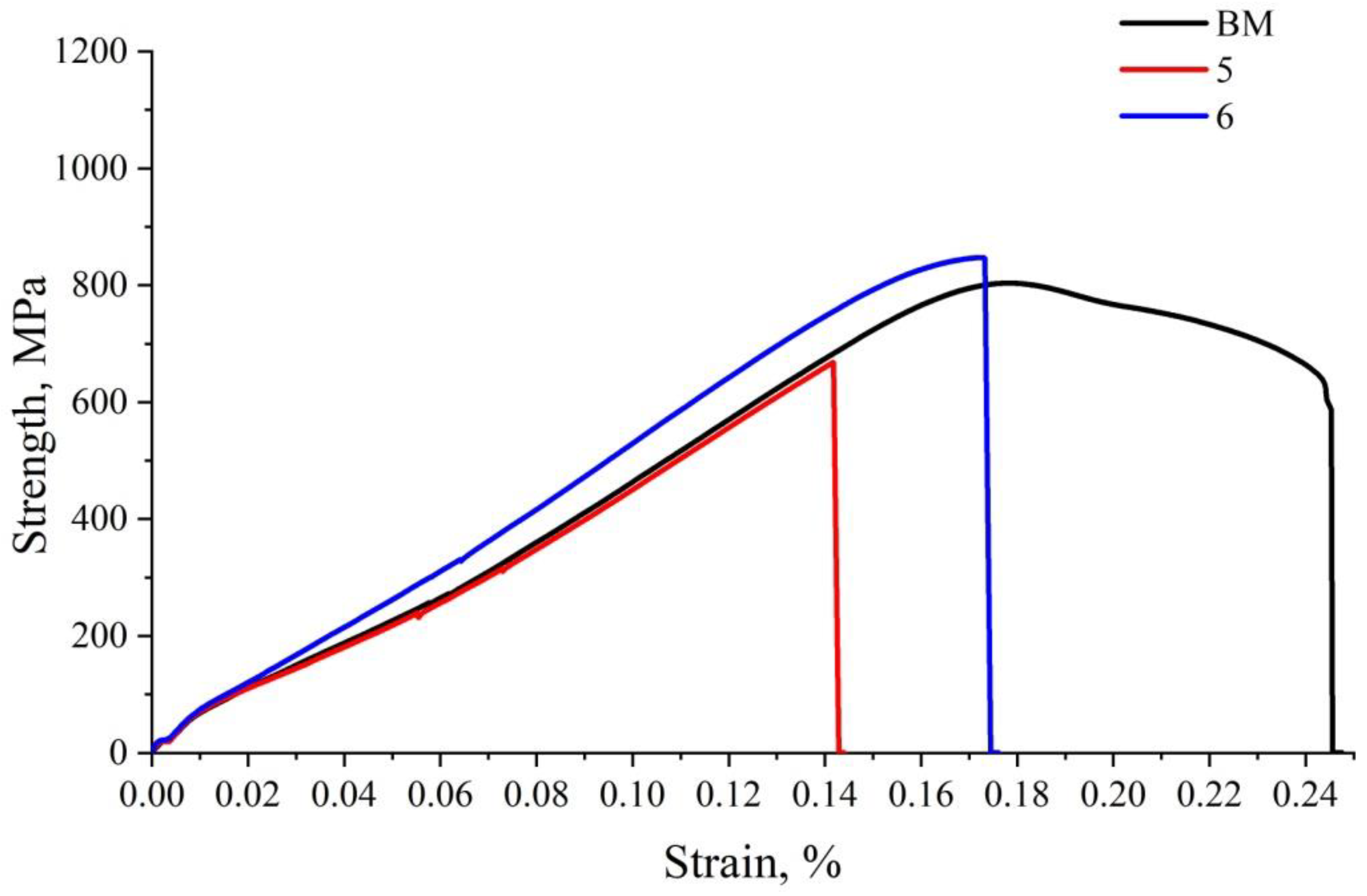
The tensile curves of FSW Ti-4Al-3Mo-1V alloy joints in comparison with the tensile curves of the base metal are shown in Figure 8. The diagrams suggest that the relative elongation of the obtained joints was lower in comparison with the base material, despite the fact that the ultimate strength of sample-2 exceeded the base metal strength. This was because of severe plastic deformation of the material during FSW, which led to grain refinement and an increase in the grain boundary area. In this case, in accordance with the Hall–Petch effect, the increase in the material strength parallels the decrease in ductility. The microstructure analysis shown in this work agrees with other results reported in the literature [37,38,39,40,52], which show that the grain size of titanium alloys decreases during FSW.
The tensile test results for Ti-4Al-3Mo-1V/Ti-6Al-4V welded joint specimens are presented in Table 6. The data indicate that the increase in the axial load on the tool had a positive effect on the weld strength characteristics.
Tensile specimens of Ti-4Al-3Mo-1V/Ti-6Al-4V welded joints before (a, c) and after (b, d) mechanical tests are shown in Figure 9. Fractures in these specimens also originated in the HAZ of Ti-4Al-3Mo-1V alloy, although subsequently they could propagate to the SZ of the weld.
SEM images of the fracture surfaces of Ti-4Al-3Mo-1V/Ti-6Al-4V alloy joints are presented in Figure 10. As in the previous case, there are tool material fragments stirred into the SZ, observed as brighter areas in the backscattered electron images. The secondary electron images also show no signs of dimpled fractures. Because of these brittle regions, fractures in the welded joints could propagate from the HAZ to the SZ during testing. In specimen-5 with a tunnel defect, fractures propagated through the void. Fractographic images of this defect showed transfer layers, which are typical of the friction stir welding process. In general, the fractures in the joints were ductile.
Figure 11 shows the tensile curves of Ti-4Al-3Mo-1V/Ti-6Al-4V alloy welded joints obtained by friction stir welding. The ultimate strength of specimen-5 was significantly less than that of Ti-4Al-3Mo-1V alloy due to the presence of a tunnel defect in it. However, in sample-6 the defect was absent and its ultimate strength was greater than that of Ti-4Al-3Mo-1V. The relative elongation also decreased compared with the base metal. The decrease in the material ductility can also be attributed to the Hall–Petch effect. Additionally, there were no fractures in Ti-6Al-4V alloy due to its greater strength characteristics.
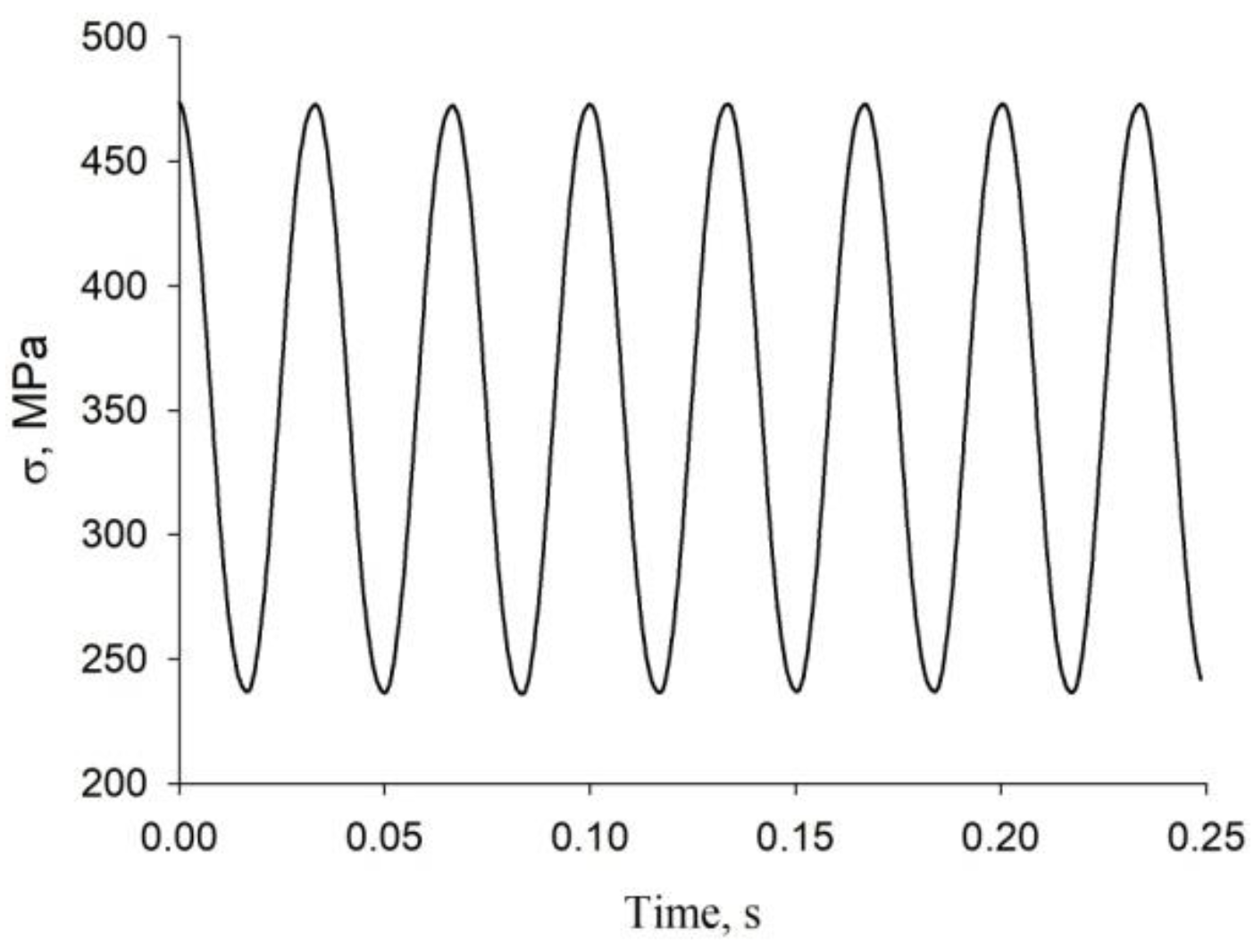
The results of mechanical fatigue tests are given in Table 7. The welded joints that showed the highest tensile strength in the tensile tests were tested for fatigue. The table uses the following notations: σmin is the minimum stress, σmax is the maximum stress, Aσ is the stress amplitude, k is the cycle asymmetry coefficient, and N is the number of cycles to failure. When testing the base metal specimens, the loading parameters were selected so that the material lasted at least 100,000 cycles.
BM specimen-1 was tested at 80% of the base metal tensile strength, and BM specimen-2 was tested at 70%. Weld specimens were tested in a mode with the minimum and maximum stresses comprising 30% and 60% of the tensile strength, respectively. The curve of stress versus time during testing of the welded specimens is shown in Figure 12.
The base metal and welded joint specimens after mechanical fatigue tests are shown in Figure 13. Unlike the tensile specimens, all fatigue specimens fractured in the SZ. This confirms that the ductility of the joints is much less than the ductility of the base metal. The fatigue fracture zone was observed in the lower part of the fracture area, and the final fracture occurred in the upper part of the joints.
The fracture surfaces of fatigue specimens after testing are shown in Figure 14. The image of Figure 14a was taken from the upper part of the joint where the final fracture in the specimen occurred. That was the place of ductile fracture, as in the tensile specimens. Figure 14b,c show the fatigue fracture surfaces in the middle part of the welded joint. They are mostly ductile, and exhibit areas with intermetallic components of the titanium alloy and tool material, where the fracture was brittle. Figure 14d shows the fatigue fracture surface in the lower part of the specimen. In contrast to the two previous locations, this zone demonstrates brittle fracture. It is worth noting that there was a HAZ in the lower part of the titanium alloy joint, which could affect the fracture behavior under fatigue loading.
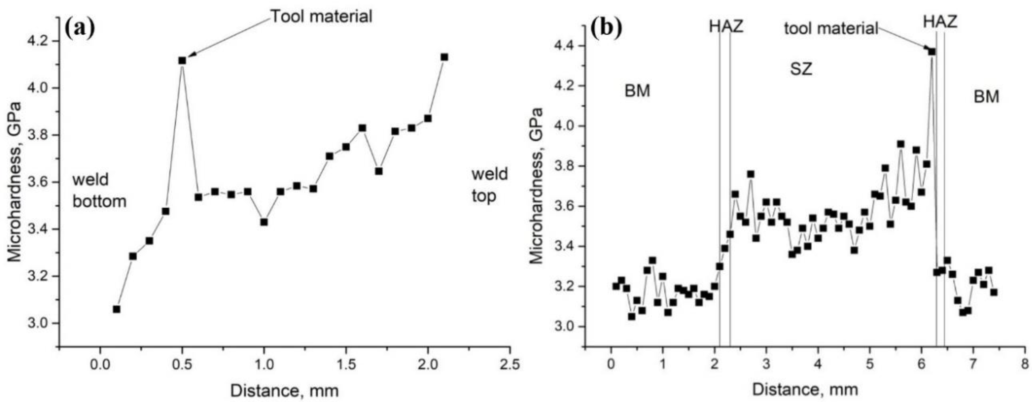
Microhardness analysis was carried out to determine the causes of such fracture behavior. A schematic of microhardness measurements for the Ti-4Al-3Mo-1V alloy joint is shown in Figure 3. These sections were chosen because they intersect both the SZ and the zone where the tool material was stirred into the joint. The microhardness in the vertical section increased from the bottom to the top of the weld. The measurement results are shown in Figure 15a. The increase in microhardness is probably due to the fact that the lower part of the joint is in the HAZ. Then, there is the SZ. However, in the central part of the joint, adhesion was due to the tool pin, while in the upper part it was due to the shoulders. The diameter of the shoulders was larger than the pin diameter, and at the same rotational speed the angular velocity of the tool shoulders was higher, resulting in better adhesion at the top of the joint. This may have contributed to the increased microhardness at the top of the joint. In addition, when the carbide indenter hit the intermetallic component layer, there was a dramatic increase in microhardness. The same increase was observed in the uppermost part of the weld. It can be assumed that the amount of intermetallic components of the tool material and titanium alloy also increased slightly in the upper part.
The microhardness in the horizontal section of the Ti-4Al-3Mo-1V alloy FSW joint obtained with a ZhS6U alloy tool is shown in Figure 15b. According to the data, the microhardness in the stir zone of the FSW joint was 3.5–3.8 GPa, which was on average 15% higher than the microhardness of the base metal equal to 3–3.3 GPa. The HAZ in the horizontal section was quite narrow, and therefore its microhardness varied insignificantly. Large deviations from the titanium alloy microhardness were observed when the indenter hit the layer of intermetallic components, whose hardness was about 4.4 GPa. The difference in microhardness between SZ and BM can be explained by the microstructure of these zones. As a rule, the grain size in the SZ of titanium alloys decreases by about a factor of 10 [38,40]. On the other hand, the strength and the microhardness of the material increases due to the Hall–Petch effect.
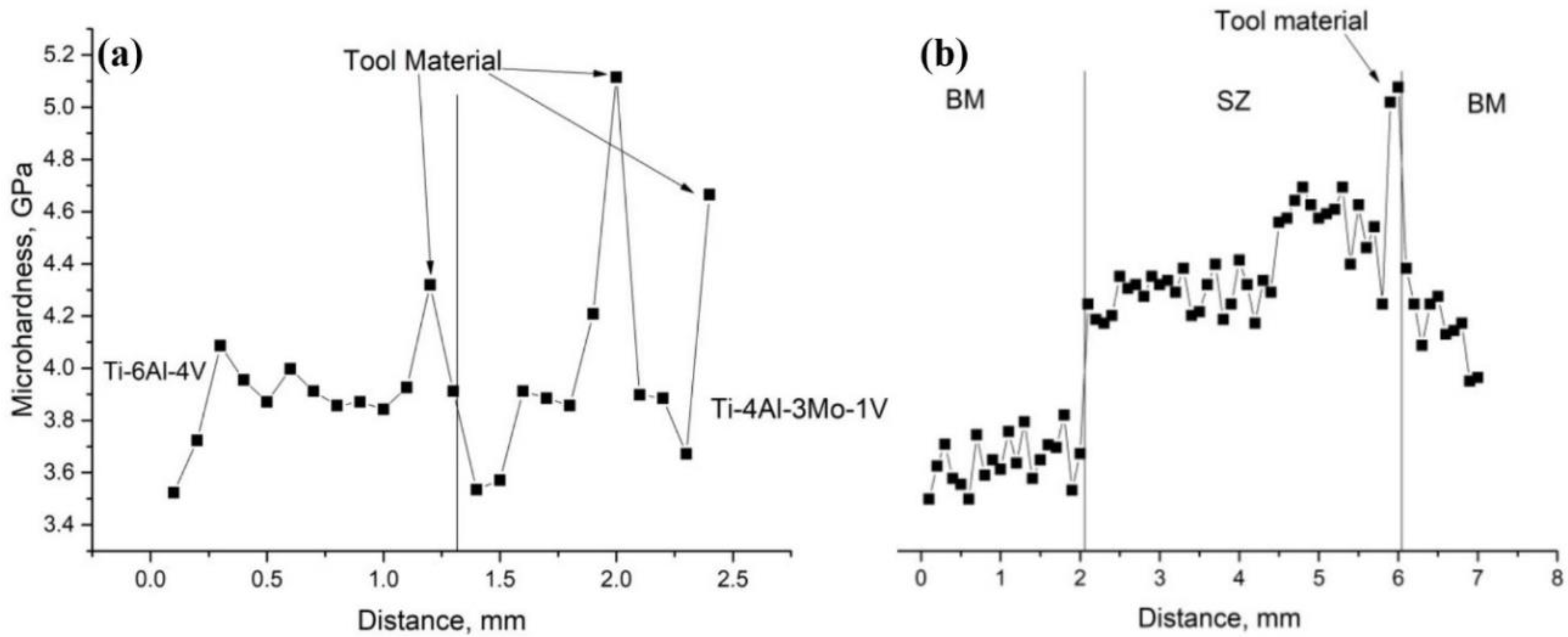
The scheme for measurements of the joint microhardness of titanium alloys Ti-4Al-3Mo-1V and Ti-6Al-4V is shown in Figure 3. These sections, as in the previous case, were chosen because they cross both the SZ and the section of the tool material mixed into the joint. In addition, these passes fall on both alloys. In the vertical section of the measurements, the microhardness of the Ti-4Al-3Mo-1V and Ti-6Al-4V titanium alloy joints increases, although in this case the increase is not so pronounced. It is shown in Figure 16a.
It is worth noting that the microhardness of the Ti-6Al-4V alloy is higher than the microhardness of the Ti-4Al-3Mo-1V alloy. Additionally, the Ti-6Al-4V alloy was in the lower part of the specimen and the Ti-4Al-3Mo-1V alloy was in the upper part of the joint of the measured specimen. Therefore, the microhardness in the lower part of the joint is even slightly greater than the central and upper part of the joint. A few sharp increases in microhardness are encountered when intermetallic components are introduced into the layer. Since the tool alloy has a complex composition, the intermetallics in the joint were also different, so their microhardness was also different.
The microhardness of the horizontal joint section of Ti-4Al-3Mo-1V and Ti-6Al-4V titanium alloys is shown in Figure 16b. Here, the microhardness changes uniformly due to the fact that the alloys are opposite each other and gradually move from one welding zone to another. So first, the microhardness was measured in the base metal zone of the Ti-4Al-3Mo-1V alloy and was about 3–3.3 GPa. The indenter then entered the SZ of Ti-4Al-3Mo-1V alloy, where it was about 3.5–3.8 GPa. After the indenter entered the SZ of Ti-6Al-4V alloy, the microhardness increased to 3.7–4 GPa. Subsequently, the indenter hit the transition zone of the SZ into the HAZ, where the layer of intermetallic components is located; there, the microhardness was about 4.3–4.4 GPa. At the end, the indenter hit the zone of the base metal in the Ti-6Al-4V alloy, the microhardness of which was about 3.4–3.6 GPa. The alloy Ti-6Al-4V has a grain size of 1–2 μm [37], and the alloy Ti-4Al-3Mo-1V has a grain size of 2–3 μm [53]. Therefore, the microhardness of Ti-6Al-4V alloy is slightly larger than the microhardness of Ti-4Al-3Mo-1V alloy. The fact that the value of microhardness of the intermetallic components layer in all cases was larger than the values of microhardness of the titanium joint suggests that the kneaded tool material could have a positive effect on the strength characteristics of the welded joint of titanium alloys.
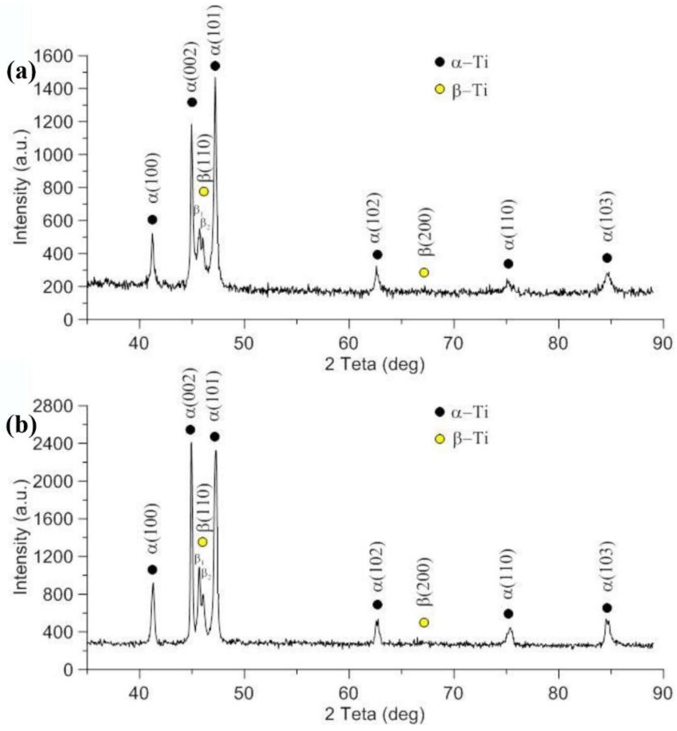
The immediate reasons for the small microhardness in the lower part of the compound and its increase in the upper part are shown by the results of X-ray analysis, which are shown in Figure 17. The phase composition in the upper part of the welded joint Ti-4Al-3Mo-1V alloy is characterized by 82 vol.% α-Ti + 18 vol.% β-Ti (Figure 17a). The decrease in the amount of the β-phase from 22 vol.% for the as-delivered state (Figure 2b) to 18 vol.% (Figure 17a) was apparently due to the phase transformations in heating and cooling. However, in the lower part of the compound, the β-phase could not be detected at all (Figure 17b). This could be the reason for the small microhardness in the lower part of the compound.
In addition, the phase composition of Ti-4Al-3Mo-1V alloy joint and Ti-4Al-3Mo-1V—Ti-6Al-4V alloy joint alloys was analyzed using XRD on cross-sectional samples. The XRD spectra are shown in Figure 18. They showed that the alloys still consisted of α- and β-phases after welding, with both the Ti-4Al-3Mo-1V alloy joint and the Ti-4Al-3Mo-1V Ti-6Al-4V alloy joint alloys having about 82 vol.% α-Ti + 18 vol.% β-Ti, as on the top surface of the joint. In other words, part of the β-phase passed into α-phase after the FSW process. It can be seen that reflex (110) β splits in the Ti-4Al-3Mo-1V alloy joint and Ti-4Al-3Mo-1V Ti-6Al-4V alloy joint, i.e., there are β-phases with large (β1) and small (β2) unit cell volumes in the welded pairs. For the Ti-4Al-3Mo-1V—Ti-6Al-4V alloy joint, it was natural to assume that β1 refers to the Ti-4Al-3Mo-1V alloy, since we observed it in the initial state, as shown in Figure 2b, and β2 refers to the Ti-6Al-4V alloy. In the case of the Ti-4Al-3Mo-1V alloy joint, the presence of two β-phases with a large (β1) and small (β2) unit cell volume may be due to the different stress state inside and outside the compound.
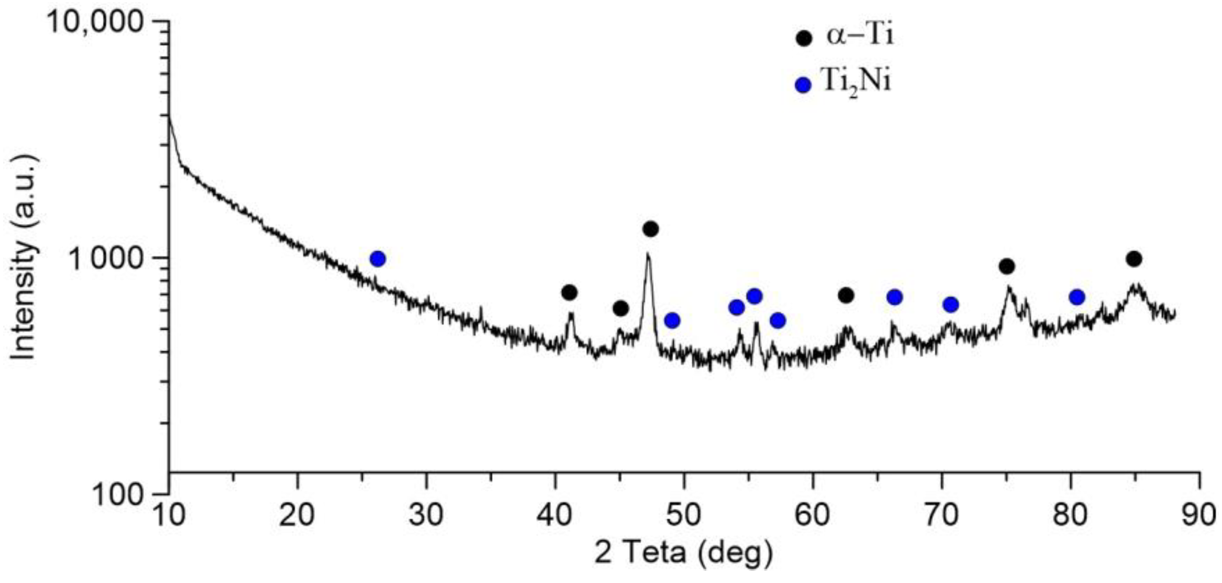
Additionally, an analysis of the phase composition was carried out on the fracture surface of the Ti-4Al-3Mo-1V alloy joint after the mechanical tests, the results of which are shown in Figure 19. It shows that compared to the initial state shown in Figure 2b, there are no β-phase peaks on the diffractogram, and additional peaks appear that can be identified as intermetallide phase Ti2Ni, which apparently appeared as a result of diffusion interaction between the welded material of alloy Ti-4Al-3Mo-1V and materials of the working FSW tool from heat-resistant nickel-based alloy. Semi-quantitative analysis of the XRD pattern using Crystal Impact’s software “Match!” showed that 82 vol.% α-Ti (reference code 00-044-1294) and 18 vol.% Ti2Ni (reference code 01-072-0442) are fixed on the fracture surface that is shown in Figure 19.
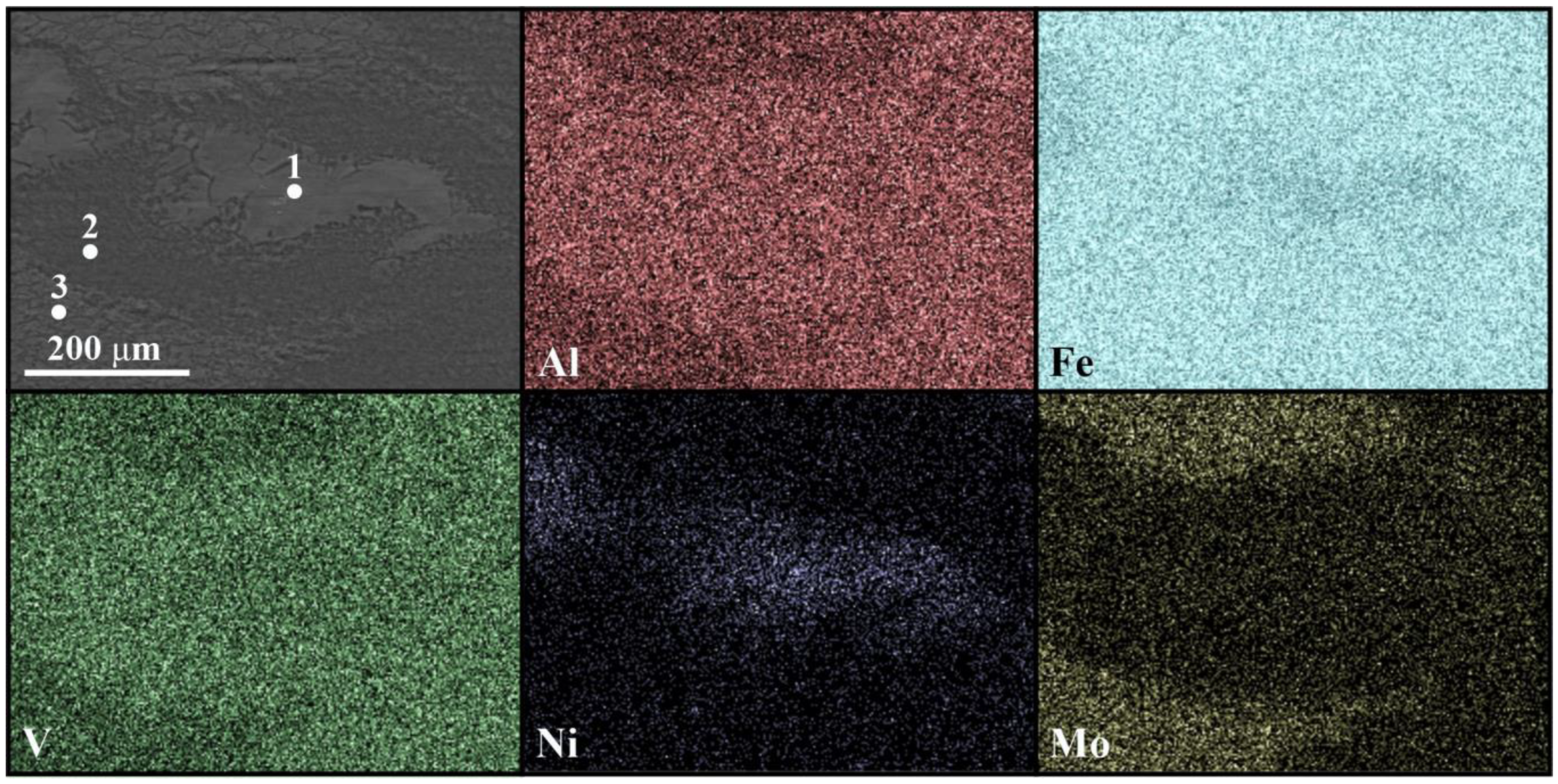
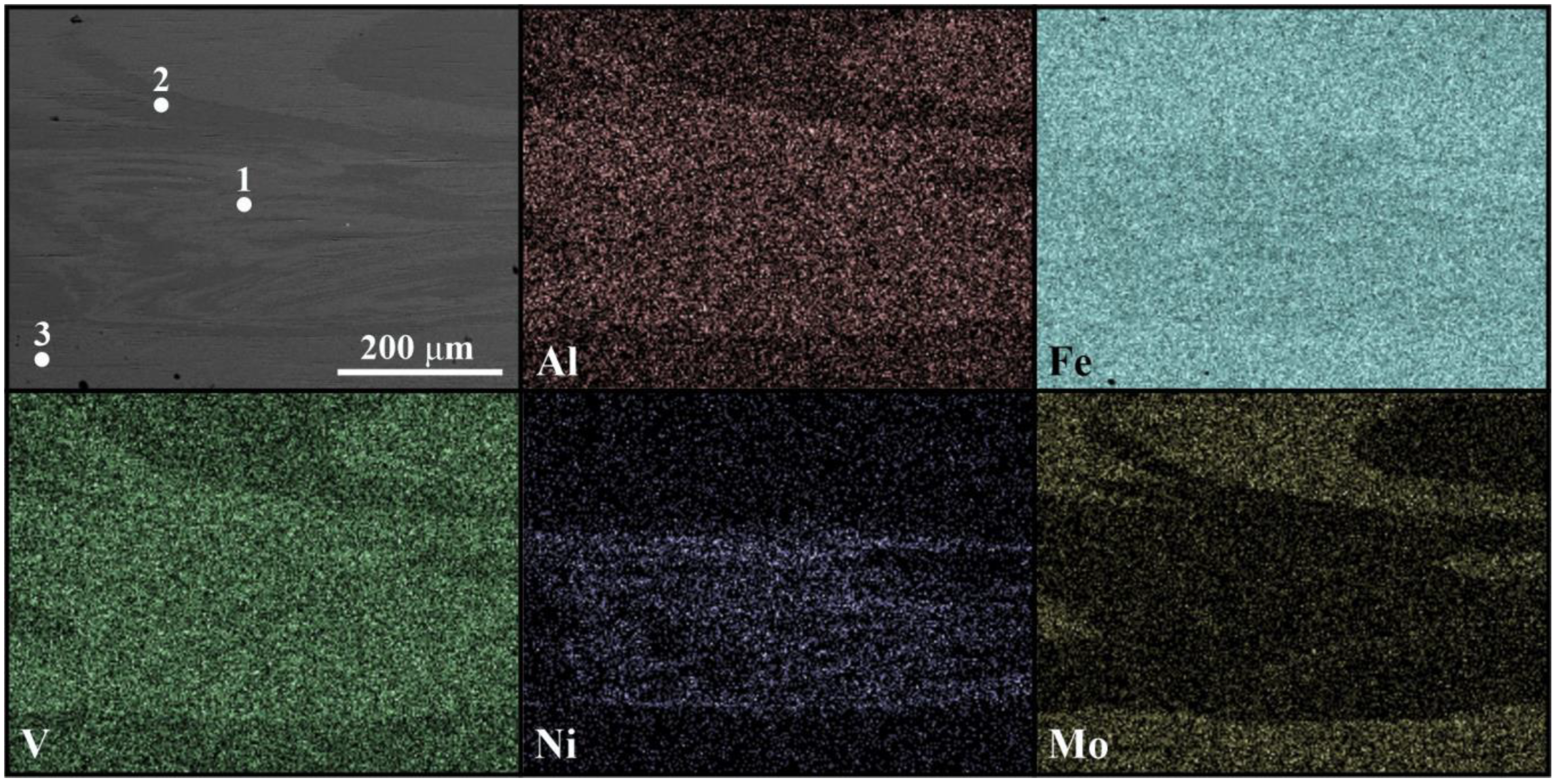
Figure 20 shows the cross-sectional SEM image of the weld section and EDX maps of the tool elements and titanium alloy Ti-4Al-3Mo-1V. The element analysis was performed on sample-2. The maps show that the major elements of the tool diffuse into the joint. The mapping shows that the tool material, consisting mainly of nickel, replaces the molybdenum in the compound. At the same time, the amount of titanium in the intermetallic component layer does not decrease significantly. It can also be said that there was not a significant increase in aluminum and vanadium in this layer. This is due to the fact that the tool alloy also contains small amounts of vanadium and aluminum in its composition. The results of elemental analysis at the items illustrated in Figure 20 are shown in Table 8.
The layer of intermetallic components is clearly seen on the SEM image of the compound area of titanium alloys Ti-4Al-3Mo-1V and Ti-6Al-4V in the cross-section, as shown in Figure 21. The figure also shows the marked points of the EDS-analysis zone with the elemental composition given below in Table 9. The dark areas (Figure 17, Table 9, item 2) contain elements inherent to the Ti-6Al-4V alloy, while the areas with light gray particles additionally contain chromium, cobalt, and nickel, or metals that originally belonged to the tool alloy. In this case, nickel, again, displaced some of the molybdenum. In turn, where the amount of molybdenum increases, the amount of aluminum and vanadium decreases, which may indicate the mutual diffusion of alloys Ti-4Al-3Mo-1V and Ti-6Al-4V. The amount of titanium in the layer of intermetallic components decreases insignificantly. This may be due to the fact that there is a small amount of titanium in the tool alloy.
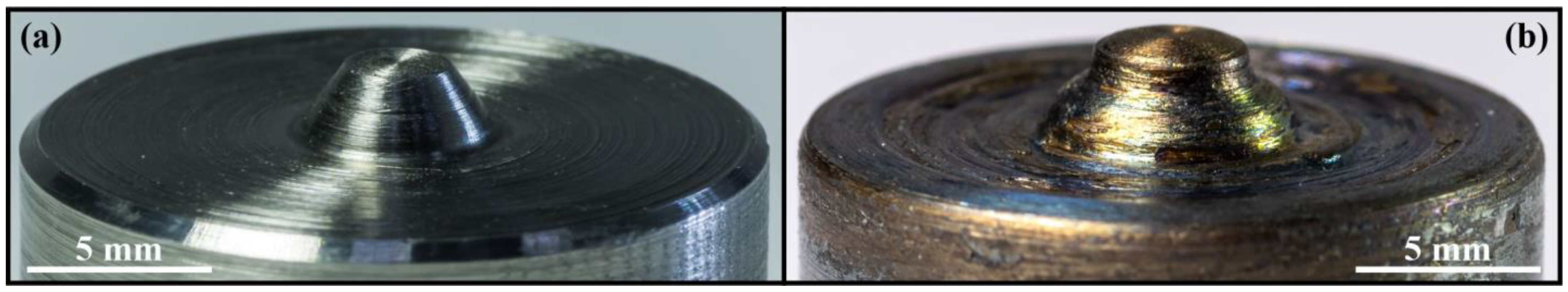
It is also necessary to mention the durability of the nickel-based high-temperature alloy tool. The welding surface of the FSW tool before and after welding is shown in Figure 22. The influence of the tool wear factor in this case is insignificant, because the tool was covered with a layer of titanium alloy during the first pass. Visual inspection of the used tool reveals minor traces of tool surface wear and a layer of titanium alloy adhesively bonded to the tool. Thus, the tool from heat-resistant alloy ZhS6U after welding of titanium (α+β)-alloys with total weld length of more than 0.5 m shows rather high resistance to accompanying temperature and mechanical stresses, and can therefore be effectively used for FSW of titanium (α+β)-alloys. Another advantage of this tool is that the titanium–nickel layer formed from the tool residue is not as brittle as the titanium borides or nitrides that are formed with tools made from the pcBN tool. This material demonstrates the greatest resistance to wear, but in the FSW process of titanium alloys, its residues embrittle the joint [33,34,35]. Moreover, nickel-based superalloys are much less expensive than other materials used for FSW tools, which makes them more attractive for FSW of titanium alloys.

4. Conclusions

This paper investigated the process of friction stir welding of titanium (α+β)-alloys with a working tool made of heat-resistant alloy ZhS6U By adjusting the welding parameters, it was possible to obtain a welded joint with a strength equal that of the base metal (samples 2, 3, and 6), despite the presence of intermetallic components of the welding tool material and titanium alloys in the joint. The obtained mechanical characteristics of the joints can be used in practical application, e.g., in strength calculations of metal connections. In addition, the resulting welding modes can be used in industry for FSW of titanium.
On the other hand, the information concerning the intermetallic layer formation in Ti-4Al-3Mo-1V and Ti-4Al-3Mo-1V/Ti-6Al-4V alloy FSW joints obtained with a heat-resistant alloy tool contributes to a better understanding of the process. The data about the formed layer of intermetallic components agree with the results obtained in previous studies. Thus, similar intermetallic components were revealed in the FSP of the Ti-6Al-4V alloy [37] and in the FSW of the α′-alloy Ti-1.5Al-1Mn [41]. However, this layer is not observed in works related to Grade2 [38,40], due to its mechanical characteristics. The layer of intermetallic components formed on the working tool will also be further investigated. The results obtained will help to determine the wear behavior of the tool and increase its durability. The general conclusion is obvious—the tool made of nickel-based alloy can be effectively used for welding titanium (α+β)-alloys.

Author Contributions

Conceptualization, A.A. and A.C.; investigation, A.A., A.C., N.S., V.K. and A.N.; resources, V.R. and E.K.; writing—original draft preparation, A.A., A.C. and N.S.; translation, A.I. and D.G.; guidance and corrections to the article, A.C. and A.I. All authors have read and agreed to the published version of the manuscript.

Funding

The work was performed according to the Government research assignment for ISPMS SB RAS (project No. FWRW-2022-0004).

Institutional Review Board Statement

Not applicable.

Informed Consent Statement

Not applicable.

Data Availability Statement

Not applicable.

Conflicts of Interest

The authors declare no conflict of interest.

References

  1. Balasundar, I.; Raghu, T.; Kashyap, B.P. Hot working and geometric dynamic recrystallisation behaviour of a near-α titanium alloy with acicular microstructure. Mater. Sci. Eng. A 2014, 600, 135–144. [Google Scholar] [CrossRef]
  2. Pilchak, A.L.; Juhas, M.C.; Williams, J.C. Microstructural Changes Due to Friction Stir Processing of Investment-Cast Ti-6Al-4V. Met. Mater. Trans. A 2007, 38, 401–408. [Google Scholar] [CrossRef]
  3. Zhu, Y.Y.; Chen, B.; Tang, H.B.; Cheng, X.; Wang, H.M.; Jia, L.I. Influence of heat treatments on microstructure and mechanical properties of laser additive manufacturing Ti-5Al-2Sn-2Zr-4Mo-4Cr titanium alloy. Trans. Nonferr. Met. Soc. China 2018, 28, 36–46. [Google Scholar] [CrossRef]
  4. Qian, T.T.; Dong, L.I.U.; Tian, X.J.; Liu, C.M.; Wang, H.M. Microstructure of TA2/TA15 graded structural material by laser additive manufacturing process. Trans. Nonferr. Met. Soc. China 2014, 24, 2729–2736. [Google Scholar] [CrossRef]
  5. Baltatu, I.; Sandu, A.V.; Vlad, M.D.; Spataru, M.C.; Vizureanu, P.; Baltatu, M.S. Mechanical Characterization and In Vitro Assay of Biocompatible Titanium Alloys. Micromachines 2022, 13, 430. [Google Scholar] [CrossRef]
  6. Bălţatu, M.S.; Vizureanu, P.; Bălan, T.; Lohan, M.; Ţugui, C.A. Preliminary tests for Ti-Mo-Zr-Ta alloys as potential biomaterials. IOP Conf. Ser. Mater. Sci. Eng. 2018, 374, 012023. [Google Scholar] [CrossRef]
  7. Callegari, B.; Oliveira, J.P.; Aristizabal, K.; Coelho, R.S.; Brito, P.P.; Wu, L.; Schell, N.; Soldera, F.A.; Mucklich, F.; Pinto, H.C. In-situ synchrotron radiation study of the aging response of Ti-6Al-4V alloy with different starting microstructures. Mater. Charact. 2020, 165, 110400. [Google Scholar] [CrossRef]
  8. Callegari, B.; Oliveira, J.P.; Coelho, R.S.; Brito, P.P.; Schell, N.; Soldera, F.A.; Mucklich, F.; Sadik, M.I.; Garcia, J.L.; Pinto, H.C. New insights into the microstructural evolution of Ti-5Al-5Mo-5V-3Cr alloy during hot working. Mater. Charact. 2020, 162, 110180. [Google Scholar] [CrossRef]
  9. Liu, F.C.; Liao, J.; Gao, Y.; Nakata, K. Influence of texture on strain localization in stir zone of friction stir welded titanium. J. Alloys Compd. 2015, 626, 304–308. [Google Scholar] [CrossRef]
  10. Zhang, W.; Ding, H.; Cai, M.; Yang, W.; Li, J. Ultra-grain refinement and enhanced low-temperature superplasticity in a friction stir-processed Ti–6Al–4V alloy. Mater. Sci. Eng. A 2018, 727, 90–96. [Google Scholar] [CrossRef]
  11. Peters, M.; Kumpfert, J.; Ward, C.H.; Leyens, C. Titanium alloys for aerospace applications. Adv. Eng. Mater. 2003, 5, 419–427. [Google Scholar] [CrossRef]
  12. Sinha, V.; Srinivasan, R.; Tamirisakandala, S.; Miracle, D.B. Superplastic behavior of Ti–6Al–4V–0.1 B alloy. Mater. Sci. Eng. A 2012, 539, 7–12. [Google Scholar] [CrossRef]
  13. Semiatin, S.L.; Seetharaman, V.; Weiss, I. The thermomechanical processing of alpha/beta titanium alloys. JOM 1997, 49, 33–39. [Google Scholar] [CrossRef]
  14. Junaid, M.; Rahman, K.; Khan, F.; Bakhsh, N.; Baig, M. Comparison of microstructure, mechanical properties, and residual stresses in tungsten inert gas, laser, and electron beam welding of Ti–5Al–2.5 Sn titanium alloy. Proc. Inst. Mech. Eng. L J. Mater.—Des. Appl. 2019, 233, 1336–1351. [Google Scholar] [CrossRef]
  15. Wang, B.; Yao, X.; Liu, L.; Zhang, X.; Ding, X. Mechanical properties and microstructure in a fine grained Ti–5Al–5Mo–5V–1Cr–1Fe titanium alloy deformed at a high strain rate. Mater. Sci. Eng. A 2018, 736, 202–208. [Google Scholar] [CrossRef]
  16. Liu, H.; Fujii, H. Microstructural and mechanical properties of a beta-type titanium alloy joint fabricated by friction stir welding. Mater. Sci. Eng. A 2018, 711, 140–148. [Google Scholar] [CrossRef]
  17. Ashton, P.J.; Jun, T.; Zhang, Z.; Britton, T.B.; Harte, A.M.; Leen, S.B.; Dunne, F.P.E. The effect of the beta phase on the micromechanical response of dual-phase titanium alloys. Int. J. Fatigue 2017, 100, 377–387. [Google Scholar] [CrossRef]
  18. Saravanakumar, R.; Rajasekaran, T.; Pandey, C.; Menaka, M. Mechanical and Microstructural Characteristics of Underwater Friction Stir Welded AA5083 Armor-Grade Aluminum Alloy Joints. J. Mater. Eng. Perform. 2022, 31, 8459–8472. [Google Scholar] [CrossRef]
  19. Saravanakumar, R.; Rajasekaran, T.; Pandey, C.; Menaka, M. A Influence of Tool Probe Profiles on the Microstructure and Mechanical Properties of Underwater Friction Stir Welded AA5083 Material. J. Mater. Eng. Perform. 2022, 31, 8433–8450. [Google Scholar] [CrossRef]
  20. Sato, Y.S.; Park, S.H.C.; Matsunaga, A.; Honda, A.; Kokawa, H. Novel production for highly formable Mg alloy plate. J. Mater. Sci. 2005, 40, 637–642. [Google Scholar] [CrossRef]
  21. Gangwar, K.; Ramulu, M. Friction stir welding of titanium alloys: A review. Mater. Des. 2018, 141, 230–255. [Google Scholar] [CrossRef]
  22. Brassington, W.D.P.; Colegrove, P.A. Alternative friction stir welding technology for titanium–6Al–4V propellant tanks within the space industry. Sci. Technol. Weld. Join. 2017, 22, 300–318. [Google Scholar] [CrossRef]
  23. Anil Kumar, V.; Gupta, R.K.; Prasad, M.J.N.V.; Narayana Murty, S.V.S. Recent advances in processing of titanium alloys and titanium aluminides for space applications: A review. J. Mater. Res. 2021, 36, 689–716. [Google Scholar] [CrossRef]
  24. Raut, N.; Yakkundi, V.; Vartak, A. A numerical technique to analyze the trend of temperature distribution in the friction stir welding process for titanium Ti 6Al 4V. Mater. Today Proc. 2021, 41, 329–334. [Google Scholar] [CrossRef]
  25. Nirmal, K.; Jagadesh, T. Numerical simulations of friction stir welding of dual phase titanium alloy for aerospace applications. Mater. Today Proc. 2021, 46, 4702–4708. [Google Scholar] [CrossRef]
  26. Su, Y.; Li, W.; Liu, X.; Gao, F.; Yu, Y.; Vairis, A. Evolution of microstructure, texture and mechanical properties of special friction stir welded T-joints for an α titanium alloy. Mater. Charact. 2021, 177, 111152. [Google Scholar] [CrossRef]
  27. Gao, F.; Guo, Y.; Yu, W.; Jiang, P.; Liao, Z. Microstructure evolution of friction stir welding of Ti6321 titanium alloy based on the weld temperature below microstructure transformation temperature. Mater. Charact. 2021, 177, 111121. [Google Scholar] [CrossRef]
  28. Du, S.; Liu, H.; Jiang, M.; Hu, Y.; Zhou, L. Eliminating the cavity defect and improving mechanical properties of TA5 alloy joint by titanium alloy supporting friction stir welding. J. Manuf. Process. 2021, 69, 215–222. [Google Scholar] [CrossRef]
  29. Raut, N.; Yakkundi, V.; Sunnapwar, V.; Medhi, T.; Jain, V.K.S. A specific analytical study of friction stir welded Ti-6Al-4V grade 5 alloy: Stir zone microstructure and mechanical properties. J. Manuf. Process. 2022, 76, 611–623. [Google Scholar]
  30. Zhou, L.; Yu, M.; Chen, W.; Zhang, Z.; Du, S.; Liu, H.; Yu, Y.; Gao, F. Microstructure and mechanical properties of friction stir processed TA5 alloy. Trans. Nonferr. Met. Soc. China 2021, 31, 404–415. [Google Scholar] [CrossRef]
  31. Rai, R.; De, A.; Bhadeshia, H.K.D.H.; DebRoy, T. Review: Friction stir welding tools. Sci. Technol. Weld. Join. 2011, 16, 325–342. [Google Scholar] [CrossRef]
  32. Farias, A.; Batalha, G.F.; Prados, E.F.; Magnabosco, R.; Delijaicov, S. Tool wear evaluations in friction stir processing of commercial titanium Ti–6Al–4V. Wear 2013, 302, 1327–1333. [Google Scholar] [CrossRef]
  33. Zhang, Y.; Sato, Y.S.; Kokawa, H.; Park, S.H.C.; Hirano, S. Stir zone microstructure of commercial purity titanium friction stir welded using pcBN tool. Mater. Sci. Eng. A 2008, 488, 25–30. [Google Scholar] [CrossRef]
  34. Wu, L.H.; Wang, D.; Xiao, B.L.; Ma, Z.Y. Tool wear and its effect on microstructure and properties of friction stir processed Ti–6Al–4V. Mater. Chem. Phys. 2014, 146, 512–522. [Google Scholar] [CrossRef]
  35. Mironov, S.; Sato, Y.S.; Kokawa, H. Friction-stir welding and processing of Ti-6Al-4V titanium alloy: A review. J. Mater. Sci. Technol. 2018, 34, 58–72. [Google Scholar] [CrossRef]
  36. Gurianov, D.A.; Fortuna, S.V.; Nikonov, S.Y.; Moskvichev, E.N.; Kolubaev, E.A. Heat Input Effect on the Structure of ZhS6U Alloy. Russ. Phys. J. 2021, 64, 1415–1421. [Google Scholar] [CrossRef]
  37. Zykova, A.; Vorontsov, A.; Chumaevskii, A.; Gurianov, D.; Gusarova, A.; Kolubaev, E.; Tarasov, S. Structural evolution of contact parts of the friction stir processing heat-resistant nickel alloy tool used for multi-pass processing of Ti6Al4V/(Cu+Al) system. Wear 2022, 488, 204138. [Google Scholar] [CrossRef]
  38. Amirov, A.I.; Eliseev, A.A.; Rubtsov, V.E.; Utyaganova, V.R. Butt friction stir welding of commercially pure titanium by the tool from a heat-resistant nickel alloy. AIP Conf. Proc. 2019, 2167, 020016. [Google Scholar] [CrossRef]
  39. Amirov, A.I.; Eliseev, A.A.; Beloborodov, V.A.; Chumaevskii, A.V.; Gurianov, D.A. Formation of α′ titanium welds by friction stir welding. J. Phys. Conf. Ser. 2020, 1611, 012001. [Google Scholar] [CrossRef]
  40. Amirov, A.; Eliseev, A.; Kolubaev, E.; Filippov, A.; Rubtsov, V. Wear of ZhS6U nickel superalloy tool in friction stir processing on commercially pure titanium Cerium in aluminum alloys. Metals 2020, 10, 799. [Google Scholar] [CrossRef]
  41. Costa, A.M.D.S.; Oliveira, J.P.; Pereira, V.F.; Nunes, C.A.; Ramirez, A.J.; Tschiptschin, A.P. Ni-based Mar-M247 superalloy as a friction stir processing tool. J. Mater. Process. Technol. 2018, 262, 605–614. [Google Scholar] [CrossRef]
  42. ASTM B265-20a; Standard Specification for Titanium and Titanium Alloy Strip, Sheet, and Plate. ASTM International: West Conshohocken, PA, USA, 2020.
  43. Balla, V.K.; Soderlind, J.; Bose, S.; Bandyopadhyay, A. Microstructure, mechanical and wear properties of laser surface melted Ti6Al4V alloy. J. Mech. Behav. Biomed. Mater. 2014, 32, 335–344. [Google Scholar] [CrossRef] [PubMed]
  44. DIN EN ISO 6892-1-2020; Metallic Materials—Tensile Testing. International Organization for Standardization: Geneva, Switzerland, 2020.
  45. Mironov, S.; Sato, Y.S.; Kokawa, H. Grain structure evolution during friction-stir welding. Phys. Mesomech. 2020, 23, 21–31. [Google Scholar] [CrossRef]
  46. Edwards, P.; Ramulu, M. Fracture toughness and fatigue crack growth in Ti–6Al–4V friction stir welds. J. Mater. Eng. Perform. 2015, 24, 3263–3270. [Google Scholar] [CrossRef]
  47. Lippold, J.C.; Livingston, J.J. Microstructure evolution during friction stir processing and hot torsion simulation of Ti–6Al–4V. Metall. Mater. Trans. A 2013, 44, 3815–3825. [Google Scholar] [CrossRef]
  48. Liu, H.J.; Zhou, L. Microstructural zones and tensile characteristics of friction stir welded joint of TC4 titanium alloy. Trans. Nonferr. Met. Soc. China 2010, 20, 1873–1878. [Google Scholar] [CrossRef]
  49. Ji, S.; Li, Z.; Wang, Y.; Ma, L. Joint formation and mechanical properties of back heating assisted friction stir welded Ti–6Al–4V alloy. Mater. Des. 2017, 113, 37–46. [Google Scholar] [CrossRef]
  50. Fall, A.; Fesharaki, M.H.; Khodabandeh, A.R.; Jahazi, M. Tool wear characteristics and effect on microstructure in Ti–6Al–4V friction stir welded joints. Metals 2016, 6, 275. [Google Scholar] [CrossRef] [Green Version]
  51. Zhou, L.; Liu, H.J.; Liu, Q.W. Effect of rotation speed on microstructure and mechanical properties of Ti–6Al–4V friction stir welded joints. Mater. Des. 2010, 31, 2631–2636. [Google Scholar] [CrossRef]
  52. Zykova, A.P.; Vorontsov, A.V.; Chumaevskii, A.V.; Gurianov, D.A.; Gusarova, A.V.; Savchenko, N.L.; Kolubaev, E.A. The Influence of Multipass Friction Stir Processing on Formation of Microstructure and Mechanical Properties of VT6 Alloy. Russ. J. Non-Ferr. Met. 2022, 63, 167–176. [Google Scholar] [CrossRef]
  53. Mosleh, A.O.; Mikhaylovskaya, A.V.; Kotov, A.D.; Sitkina, M.; Mestre-Rinn, P.; Kwame, J.S. Superplastic deformation behavior of ultra-fine-grained Ti-1V-4Al-3Mo alloy: Constitutive modeling and processing map. Mater. Res. Express 2019, 6, 096584. [Google Scholar] [CrossRef]
Figure 1. General view of the FSW process (a,b); schematic of friction stir welding of titanium alloys with an argon gas blanket of the welding joint and liquid tool-cooling (c); schematic of a cross-sectional specimen and tensile specimen (d).
Metals 13 00222 g001
Figure 2. XRD spectra of as-received Ti-6Al-4V (a) and Ti-4Al-3Mo-1V alloys (b).
Metals 13 00222 g002
Figure 3. Cross-sectional metallographic image of Ti-4Al-3Mo-1V alloy joint specimen №1 (a), №2 (b), №3 (c), №4 (d), and Ti-4Al-3Mo-1V—Ti-6Al-4V alloy joint specimen №5 (e), №6 (f): 1,2—track of microhardness measurement.
Metals 13 00222 g003
Figure 4. Microstructure of Ti-4Al-3Mo-1V alloy joint specimen №1 (a), №2 (b), №3 (c), №4 (d), and Ti-4Al-3Mo-1V—Ti-6Al-4V alloy joint specimen №5 (e), №6 (f).
Metals 13 00222 g004
Figure 5. FSW joint tensile specimens of Ti-4Al-3Mo-1V titanium alloy: top view before (a) and after testing (b), and bottom view before (c) and after testing (d).
Metals 13 00222 g005
Figure 6. SEM/SE images of the fracture surface of Ti-4Al-3Mo-1V welded joint in heat-affected zone at different zoom levels (ac).
Metals 13 00222 g006
Figure 7. SE/BSE images and results of fractography analysis of the Ti-4Al-3Mo-1V weld, which was destroyed in the stir zone at different zoom levels (ac).
Metals 13 00222 g007
Figure 8. Stress–strain curves for Ti-4Al-3Mo-1V welds obtained with different FSW parameters.
Metals 13 00222 g008
Figure 9. FSW joint tensile specimens of Ti-4Al-3Mo-1V/Ti-6Al-4V titanium alloys: top (a) and bottom view before testing (b), and top (c) and bottom view after testing (d).
Metals 13 00222 g009
Figure 10. SE/BSE images and results of fractography analysis of Ti-4Al-3Mo-1V—Ti-6Al-4V weld, which was destroyed in area of stir zone at different zoom levels (ac).
Metals 13 00222 g010
Figure 11. Stress–strain curves for Ti-4Al-3Mo-1V—Ti-6Al-4V welds obtained with different FSW parameters.
Metals 13 00222 g011
Figure 12. Stress–time curve for fatigue testing of welding joints.
Metals 13 00222 g012
Figure 13. Specimens of base metal (a), Ti-4Al-3Mo-1V alloy FSW joints (b), and Ti-4Al-3Mo-1V/Ti-6Al-4V alloy FSW joints (c) after fatigue testing.
Metals 13 00222 g013
Figure 14. SE images of the fracture surfaces of welded joint after fatigue testing in the upper (a), middle (b,c), and lower part of the weld (d).
Metals 13 00222 g014
Figure 15. Microhardness of the welded joint Ti-4Al-3Mo-1V alloy obtained by friction stir welding in a vertical direction (a), and obtained by friction stir welding in a horizontal direction (b).
Metals 13 00222 g015
Figure 16. Microhardness of the welded joint Ti-6Al-4V and Ti-4Al-3Mo-1V alloys obtained by friction stir welding in a vertical direction (a), and obtained by friction stir welding in a vertical direction (b).
Metals 13 00222 g016
Figure 17. XRD spectra of the welded joint Ti-4Al-3Mo-1V alloy on the top surface (a) and on the bottom surface (b).
Metals 13 00222 g017
Figure 18. XRD spectra of the Ti-4Al-3Mo-1V alloy joint (a) and the Ti-4Al-3Mo-1V—Ti-6Al-4V alloy joint (b).
Metals 13 00222 g018
Figure 19. X-ray diffraction analysis of the fracture surface of the titanium alloy joint surface destroyed after mechanical testing.
Metals 13 00222 g019
Figure 20. SEM image of the joint section and EDX maps of the tool and titanium alloy elements in the Ti-4Al-3Mo-1V joint.
Metals 13 00222 g020
Figure 21. SEM image of the joint section and EDX maps of the tool and titanium alloy elements in the Ti-4Al-3Mo-1V and Ti-6Al-4V joint.
Metals 13 00222 g021
Figure 22. FSW tool produced from alloy ZhS6U before welding (a) and after ≈0.5 m of welding (b).
Metals 13 00222 g022
Table 1. Element composition of ZhS6U alloy (wt%).
FeNbTiCrCoWNiAlMoC
≤10.8–1.22–2.98–9.59–10.59.5–1154.3–62.75.1–61.2–2.40.13–0.2
CeSiMnPSZrBiBYPb
≤0.02≤0.4≤0.4≤0.015≤0.01≤0.04≤0.0005≤0.035≤0.01≤0.01
Table 2. Element composition of Ti-4Al-3Mo-1V alloy (wt%).
FeCSiVNTiAlMoZrOHOther
≤0.25≤0.01≤0.150.9-1.9≤0.0586.85–92.83.5–6.32.5–3.8≤0.03≤0.15≤0.0150,3
Table 3. Element composition of Ti-6Al-4V alloy (wt%).
FeCSiVNTiAlZrOHOther
≤0.6≤0.1≤0.13.5–5.3≤0.0586.45–90.95.3–6.8≤0.3≤0.2≤0.0150,3
Table 4. Friction stir welding parameters.
Weld, №ω, rpmFP, kNFw, kNV, mm/minL, mm
137523268625
2375232686180
3375252886100
4375273086100
537523268685
637527308685
Table 5. Effect of FSW parameters on the strength of the Ti-4Al-3Mo-1V joint.
Weld, №Axial Force, kNWeld Strength of 1 Test, MPAWeld Strength of 2 Test, MPAWeld Strength of 3 Test, MPAWeld Strength of 4 Test, MPAAverage Strength of the Weld, MPA
BM-795768804-788
226791814823822813
328800784769730771
430743752766737750
Table 6. Effect of FSW parameters on the strength of the Ti-4Al-3Mo-1V—Ti-6Al-4V joint.
Weld, №Axial Force, kNWeld Strength of 1 Test, MPAWeld Strength of 2 Test, MPAWeld Strength of 3 Test, MPAAverage Strength of the Weld, MPA
BM-795768804788
526589669-629
630838848-843
Table 7. Fatigue test parameters.
Weld, №σmin, MPaσmax, MPaAσ, MPakN
BM-12376313940,37510,223
BM-22375523150,42961,310
BM--32374732360,501158,089
2–12374732360,50111,111
2–22374732360,50114,495
2–32374732360,50116,935
6–12374732360,5014070
6–22374732360,5017134
Table 8. Results of the chemical composition analysis performed on the joint section.
SampleChemical Element Content, w/at%
AlTiVCrFeCoNiMoW
15.91/10.4376.05/75.623.63/3.41.32/1.21-1.42/1.159.37/7.6-2.3/0.6
25.59/9.5489.17/85.764.8/4.34-0.44/0.36----
33.85/6.7892.07/91.21-----4.07/2.01-
Table 9. Results of the chemical composition analysis performed on the section of the joint.
SpektrChemical Element Content, w/at%
AlTiVCrCoMoNi
15.41/9.3384.39/82.004.30/3.930.63/0.570.66/0.52 4.60/3.64
25.35/9.1589.87/86.254.78/4.32
33.53/6.2292.86/91.99-- 3.61/1.79
Disclaimer/Publisher’s Note: The statements, opinions and data contained in all publications are solely those of the individual author(s) and contributor(s) and not of MDPI and/or the editor(s). MDPI and/or the editor(s) disclaim responsibility for any injury to people or property resulting from any ideas, methods, instructions or products referred to in the content.

