Article

Welding of Low Carbon Steel Tubes Using Magnetically Impelled Arc Butt Welding: Experimental Investigation and Characterization

by
Mukti Chaturvedi
1,
Arungalai Vendan Subbiah
1,
Mohammed Y. Tharwan
2,
Sharaf Al Sofyani
3,
Vladimir Kachinskiy
4,
Sharanabasavaraj Radder
1,
Ashraff Ali Kaveripakkam Suban
5,
Essmat Showman
6,
M. Fattouh
6,* and
Ammar H. Elsheikh
7
1
Electronics and Communication, School of Engineering, Dayananda Sagar University, Bangalore 560068, India
2
Mechanical Engineering Department, College of Engineering, Jazan University, KSA, 114 Almarefah Rd. 45142, Jizan 82817, Saudi Arabia
3
Industrial Engineering Department, College of Engineering, Northern Border University, Arar 91431, Saudi Arabia
4
E.O Paton Electric Welding Institute, 03150 Kyiv, Ukraine
5
Department of Mechanical Engineering, C. Abdul Hakeem College of Engineering & Technology, Ranipet, Arcot 632509, India
6
Department of Mechanical Engineering, Faculty of Engineering, University of Blue Nile, Al Roseires, Damazeen 143, Sudan
7
Department of Production Engineering and Mechanical Design, Tanta University, Tanta 31527, Egypt
*
Author to whom correspondence should be addressed.
Metals 2022, 12(11), 1965; https://doi.org/10.3390/met12111965
Submission received: 6 October 2022 / Revised: 9 November 2022 / Accepted: 11 November 2022 / Published: 17 November 2022
(This article belongs to the Special Issue Advanced Welding Technology in Metals II)

Abstract

:
Magnetically impelled arc butt (MIAB) welding is a solid-state technique of welding that utilizes the heating effect of a high-speed rotating arc for the formation of the weld. The process exhibits lower time and power consumption compared to conventional solid-state processes for tube–tube joining. However, the available research reports on MIAB welding of Mild Steel (MS)1018 are still inadequate and lack the details required for extending the applications of this process. Hence, this study was undertaken to investigate MIAB welding for MS 1018 tubes. Experimental investigations were performed on a specifically designed and newly fabricated MIAB welding machine. The experimental trials involved varying the process parameters and understanding their influence on joint strength and other weld characteristics. Microstructure of the MIAB weld consisted of acicular ferrite which differed from the microstructure of the heat-affected zone. These trials helped to arrive at the optimum parametric window that specified the ranges of key parameters viz. welding current, upset current, and welding time to yield an efficient weld. Chemical analysis of the weld indicated the absence of inter-metallics. MIAB welding of MS1018 showed greater strength and integrity at the joint when optimum ranges of the process parameters were maintained, and is feasible for deployment as economizer coils in boilers, pressure part tubes, and automobile tubular component joining applications.

1. Introduction

Magnetically impelled arc butt (MIAB) welding involves striking an arc between two coaxially placed tubes. This is followed by the interaction of the axial component of arc current and the radial component of an external magnetic field that creates Lorentz force. This force acts on the arc and impels it around the joint line with an approximate linear speed of 200 m/s that uniformly heats the tube surfaces up to their solidus temperature [1,2]. The softened faying surfaces are then forced into penetration by forging to form a weld. The schematic of this process, Figure 1, indicates the components involved in this welding process. The schematic shows a front view of the MIAB welding arrangement indicating the axial placement of weld tubes, permanent magnets around the tubes, and formation of the arc in the tube gap. It also points to the orientation of the radial and axial components of the magnetic field created due to arc current, due to the permanent magnets, and the force created with their interaction.
The process can be divided into four stages viz. current flow in the tubes, arc formation and sustenance, heating, and forging [3]. These stages have distinct requirements of time duration and amperage guided by the process and the material requirements. Material properties are used to estimate the energy required to bring the material to its solidus temperature. The time required for this weld is significantly smaller than that required for other solid-state welding processes. Unlike the friction welding technique, this process can be used for varying geometries [1,2,3].
The MIAB welding process is executed in the following sequence of steps:
  • Stage I—arc generation and sustenance—the clamped tubes to be welded are brought in contact and the power supply is turned on to allow current flow;
  • Stage II—tubes are then retracted to create a gap of 1 to 2 mm, for the creation of an arc. The tube gap is set based on the applied voltage, amperage, material properties, and geometry. The sustenance of the arc depends on the arc gap and the applied voltage [4];
  • Stage III—arc rotation and heating-pre-programmed arc current and time are applied based on prior trials and technical reports. Interaction of the welding current and the magnetic field causes the arc to rotate along the periphery and in zigzag movement [5] on the faying surfaces. The heating effect of the rotating arc causes the weld region temperature to rise to the material’s solidus temperature. The faying surface gets heated up and is plasticized;
  • Stage IV—upset and arc quenching—in the plasticized state, the two tubes are forged together by the application of preset upset pressure. When the two surfaces fuse together, the arc gets quenched. The plasticized material and the impurities that have lower melting temperature gets expelled out of the interface and form the weld bead. The expelled material is deposited on the periphery of the weld interface in the form of a flash and is termed as reinforcement [2,3]. Figure 2 shows the different stages of the process.
The Lorentz force and the velocity of the arc are related by Equation (1) [6]. The current and the magnetic field should be maintained for the arc heating to progress.
V a r c = F k 1 e k t m
where Varc—velocity of the arc, F—Lorentz Force, k—constant of air resistance, m—mass of the arc, t—time duration
F = B I w L g
where B—Magnetic flux density, Iw—Welding current, Lg—length of arc [6].
Arc velocity varies in different phases of the process [7]. In the initial phases, arc velocity increases linearly with time as it gets impelled on the tube periphery. On stabilization, the arc can be visualized as a rotating ring between the weld surfaces. The speed is maintained till the surface heats up. The temperature rise with the heating causes localized melting at the surface, which forms a short circuit causing the arc to quench. Localized melting occurs in low-melting phases and eutectics and in the structural range around the grain boundaries [8]. The grain boundaries are subjected to segregation during solidification and often have a lower solidus temperature than the matrix material or the structural matrix. The structural matrix is not modified with localized melting. Also, the viscosity of localized molten iron rises first and then decreases with the decreasing temperature; the viscosities before and after the turning point are the viscosity property and the solidification property, respectively [9]. The melted material forms a bridge in the gap between the weld tubes that may cause unstable arc rotation. Instability in the arc velocity [1,2,3,5,10] and may lead to the quenching of the arc. The two tubes are then forged together along with excess arc current for fusing the butt surfaces before arc quenching occurs. Table 1 describes the stages of this welding technique with the approximate range of operating current and time durations, derived from preliminary experimental trials for welding of MS1018 tubes.
Investigations on MIAB welding started early in the 1950s in Europe and several research developments further revealed the merits of this process and promoted it as an industry-friendly welding technique. From the 1980s, MIAB welding was employed in the automobile industry for hollow tube components such as pneumatic springs, brake rods, shock absorbers, and even for safety-critical applications like boiler heat exchangers, economizer coils, etc. [1,2,3,5]. MIAB welding has the advantages of being a solid-state process, shorter weld cycle, lesser input energy requirement, no rotation of any component and lesser loss of material. In comparison to other solid state welding processes, MIAB welding has the advantage of cost-efficient welds with better control and reliability. The distinct feature of this process is that it can form efficient welds without any surface preparation or even with an offset in the axial positioning of the weld tubes. There are limitations to this process for application to tubes of thickness larger than 6mm, which has restricted its wide adaptability in the manufacturing industry. This has led to further studies on the feasibility of this process for thick tubes with the conventional setup. The conditions that are required for a successful MIAB are [3]:
(i)
Active spots of the rotating arc on the two weld surfaces should be nearly the same measurement as the weld thickness;
(ii)
Any Nonuniformity at the faying surfaces should be less than 0.7 mm.
The experimental trials reported in this paper were performed on a specifically designed and fabricated MIAB welding machine for research purposes. The MIAB welding process was implemented for ferrous materials and extending this process for non-ferrous materials was not explored significantly. The work reported in this paper is limited to welding of tubes and pipes. Implementing this method of joining for other shapes such as plate–plate, plate–tube will need modifications in the design of the welding machine.
The magnitude of the magnetic field is the basis of arc rotation and controls its placement in the tube gap and velocity. Magnetic field distribution depends on the gap length between the tubes and the magnet position [11,12]. The heat generated on the peripheral surface of the weld metal with the arc rotation undergoes losses in the form of heat convection and radiation [13,14,15]. These losses were assumed to be negligible in the research works that describe this welding process. Arc movement in the tube gap from inner to outer diameter may cause non-uniform heat generation, which is detrimental to the weld quality [16,17].
Effective design of the electromagnetic system is a crucial task in the MIAB system design since the magnetic flux density affects the arc rotation and the weld quality. Magnetic flux density depends on the exciting current, the gap between the weld pieces, the position of the exciting coil, and the relative permeability of the weld pieces [18]. It has been observed that on initiation of the arc, it is pushed to the inner diameter (ID) due to a magnetic blow effect. This is caused by the interaction of the arc’s natural magnetic field with tube geometry, thereby creating a high gradient external magnetic field. This strong magnetic field around the outer diameter (OD) blows the arc towards ID [19]. The spinning arc in combination with the thermal conductivity of the welded metal creates uniform heating at the joint [18]. Arc rotation speed depends upon the magnitude of the welding current and the magnetic field [20]. The high speed of arc rotation is critical to the MIAB weld process to avoid intermediate temperature drop of the metal part during every cycle. The speed should be optimum to cause the temperature rise of the weld up to the solidus temperature resulting in a short arc heating phase of the weld cycle. The maximum linear speed of the arc movement is 870 km/h and depends directly on the radial magnetic flux density [17]. It was observed that in thick tubes, the arc rotates at a slow speed around the inner surface in comparison to that at the outer edge of the tubes [21]. This variation in arc speed deteriorates the weld quality and is caused by the temperature gradient at the weld before the upset stage [15,16].
The weld material experiences phase transformation in the process based on the rate of change of temperature. These transformations may result in residual stresses and volumetric phase changes which have been analyzed by several researchers. Solutions have been proposed to keep the transformations and the stresses in check [22,23,24,25]. MIAB welding has been predominantly adopted for the joining of ferrous tubes in the the European automotive industry for the manufacturing of various parts. It has also been explored in the power industry for the manufacturing of heat exchangers, boiler tubes, and other high-pressure parts which find utility in corrosive and hazardous environments [26,27,28,29].
Kachinskiy et al. [3] listed the essential conditions for an efficient weld with respect to wall thickness and gap non-uniformity. Wall thickness should be nearly the same as the size of the active spots of the arc and the non-uniformity on the weld surfaces should be less than 0.7 mm. With the optimum distribution of the magnetic field induction, the arc can be drifted to the outer edge of the faying surfaces for uniform heating of tube ends. Iordachescu et al. [25] observed increased arc stability with a longitudinal magnetization system having 8 solenoids connected in series and positioned in parallel with the longitudinal axis of the tube. This system improved the arc rotation stability by concentrating the magnetic field onto the tube wall. The use of four coils in two half shells also made the welding equipment portable. Faes et al. [28] developed a control method for regulating the arc current while moving over the entire cross-sectional area of the pipe butts and bottom. Sato et al. [7] inferred from their experiments that as the process temperature rises beyond the Curie point, tube joints experience a loss of magnetic properties in the region around the weld gap. This is followed by the quenching of the arc and the completion of the weld sequence. No shielding gas is used in this process and to achieve good weld quality, the arc rotation frequency should be high to avoid instantaneous solidification of the softened metal. The high-speed rotating arc causes the temperature to rise to a level that causes intensive metal evaporation [3]. The shielding created by metal evaporation prevents the oxidation of the plasticized metal surfaces.
Arungalai Vendan et al. [29,30] manifested that radiography tests for MIAB welds may yield unsuccessful results. This is possible because thin layers of oxides or non-protruding, flattened inclusions may be too small to detect. These areas lead to weakened welds with low adhesion of layers and pore formation due to the interaction of gas molecules.
Researchers have published simulation and experimental results for different grades of steel tubes and pipes having an outer diameter larger than 40 mm which find application in various structural and pressure part components. The automobile industry involves the manufacturing of parts that utilize mild steel tubes of 21.5 mm, 25 mm, and 27 mm OD with the thickness of 1–3 mm. Automobile manufacturing industries have been employing conventional welding techniques like flash butt welding or induction pressure welding for the manufacture of these parts. Manufacturing techniques are now being explored that have low energy requirements, cause lower losses of material, and have reduced pollution effects. The MIAB welding process, in its previous trials, has been observed to meet these requirements to a large extent in comparison to other solid-state welding techniques. This process produces reliable and efficient welds, has a short weld cycle, is automated, and requires no significant surface preparation or cleaning time. On these lines, the experimental facilities, process results, and characterization reports for 20–27 mm OD MS 1018 tubes are found to be inadequate in the existing literature. Moreover, MIAB welding is an advanced joining technique but its standards for various applications are yet to be established. Several technical challenges apart from those discussed in the literature reports remain unexplored. Thus, this work has been taken up to address some challenges and their solutions, and for the generation of datasets for the joining of MS1018 tubes, and to subsequently characterize the welding process for understanding its feasibility and reliability.
As part of this work, experimental and parametric analysis was performed for mild steel tubes and a relationship between weld characteristics and the process parameters was established for the attainment of efficient welds. This work reports the experimental observations of MIAB welding and destructive testing results for MS tubes of the selected dimension, which are not found in the existing literature. The experiments were conducted on the newly fabricated MIAB welding machine, specifically designed for welding 21 mm to 27 mm thick metal tubes. The data generated formed the database for the parametric study of this process. The optimum parametric ranges obtained from the results can be extrapolated for use in the joining of tubes of different dimensions and can also form the inputs for arriving at parameter and response-dependency equations. This study outcome may lead to the establishment of industry standards for this welding process for various applications and add new information to the existing database along with the creation of optimized parameter ranges for the MIAB welding process for MS samples.

2. Experimental Trials and Tests

2.1. Experimental Setup

The experiments were carried out on the Magnetically Impelled Arc Butt (MIAB) welding setup available at Dayananda Sagar University, Bangalore. Figure 3a shows the complete MIAB welding setup that includes the following major components:
(i)
Welding Unit, Figure 3b includes:
  • weld heads—Figure 3c. Weld heads (sample holders) can be replaced to accommodate tubes of 21 mm, 25 mm and 27 mm OD
  • Mechanical System—Figure 3e for the movement of the weld heads;
(ii)
power supply module—Figure 3d. 3-phase supply of 440 V, 50 Hz is given to the module which converts it to DC and is supplied to the welding machine;
(iii)
control panel for current and time settings—Figure 3f is used to pre-set the amperage and the time duration for the two stages of this welding process. The pre-set values depend upon the parametric analysis of the MIAB welding process using experimental study or by using trial and error technique. Previous literature also suggests an operable range for the parameters, based on the material to be welded.
Figure 3. (a) MIAB Welding Setup; (b) welding unit; (c) weld heads; (d) power supply unit; (e) mechanical system; and (f) control panel.
Metals 12 01965 g003
The mechanical system generates the pressure required for retracting the tubes in the arc formation stage and for forging the tubes in the upsetting stage. The hydraulic system using oil of HP grade 46 is supplemented by a pneumatic arrangement enabled by Nitrogen in the accumulator. The combined pressure drives the axial movement of one weld head, Figure 3c. Hydraulic system. Figure 3e includes the hydro motor, pressure sensors, cylinders, pipeline, and sleeves of high pressure. This mechanism controls the flow of hydraulic oil at a pre-defined pressure that varies with the material properties. The pressure of the hydraulic system is maintained at a higher level than the pneumatic pressure. Preliminary trials conducted on the particular MIAB welding machine indicated this as the requirement for the formation and sustenance of the arc. This system causes retraction of the tubes in the initial stage, for arc creation which is enabled by the controlled flow of working fluid in the hydro-cylinders [5]. The hydraulic arrangement is pre-programmed to forge the tubes together at a pressure of 3–4 MPa, depending on the material dimensions and properties.
Trials were carried out with MS1018 tubes of 27 mm Outer Diameter (OD) and 1.5–2 mm thickness with a maximum cross-sectional area of 240 mm2.
The chemical composition of MS1018 is listed in Table 2.

2.2. Parametric Influence and Operating Range Selection

2.2.1. Parametric Influence

The hydraulic system in the MIAB welding machine is responsible for the retraction of the tubes to result in arc creation and then forging the softened weld surfaces of the tubes into weld formation. The nitrogen accumulator system is used as an additional pressure-enhancing system to support the hydraulic pressure. The design of the mechanical system and the individual pressure selection has a significant role in the arc establishment and for the arc to attain the required speed. Hydraulic pressure should be larger than the nitrogen pressure in the accumulator for arc establishment and its sustenance [30,31].
Smaller arc rotation time with higher arc rotation velocity causes a larger centrifugal force to act on the plasticized material and the impurities to expel them towards the periphery of the tube. For a lower value of current in the heating and upset stage, rotation time significantly affects the microstructure at the weld interface. Increased arc rotation time enhances the plasticized material at the interface which is not sufficiently heated with a lower arc current. Increased plasticized material with a larger rotation time reduces the defective weld interface by the easy flow of the material in the upset stage. Samples welded with higher arc rotation current experience appropriate heating of the faying surfaces and have a lower impact on the rotation time [20].
Lower arc current for a lower time duration causes insufficient heating and softening at the weld surface, causing insufficient penetration, resulting in a failed tensile test at the weld. With an appropriate current and time setting to ensure required heat input, tensile tests may exhibit failure at the base metal and not at the weld. Weld microstructure differs for a varying range of arc current, with polygonal ferrite and bainite formation for high arc current, and acicular ferrite formation for lower current. The formation of acicular ferrite is also observed with higher quenching in which dislocation substructures form the nucleating sites for acicular ferrite. Increasing the arc rotation current will also cause an increase in the fusion zone with higher heat input [31].
Arc upset current controls the width of the TMAZ in the process as it governs the expulsion of the excess material and the surface impurities. Increased upset current results in reduced width of the TMAZ region. An upset current causes significant defect formation at the weld interface with lower arc currents. A lower arc rotation current has been observed in previous literature to cause the formation of a light band zone with a more ferritic structure along the weld line due to incomplete expulsion of the decarburized zone [32].
Arc current is responsible for the required heating of the weld surfaces up to the solidus temperature to cause the plasticizing of the material, while the upset current affects the expulsion in the upset stage. A high upset current can cause excess surface metal expulsion which may result in the formation of voids at the weld interface. Lower arc current and high upset current result in the predominant void formation and failed weld. The values of current, time and pressure depend on the material properties and geometry.

2.2.2. Operating Range Selection

The initial selection of process parameters for the welding of MS1018 tubes was based on the trial-and-error method. The selection of process parameters for the welding of MS1018 tubes was based on preliminary experimental work on the newly fabricated MIAB welding machine and the trial-and-error method. The trials were made with different ranges based on reported results for other dimensions of tubes [33]. The first set of trials involved experiments for arriving at the required hydraulic pressure and stage I current. The operational range of the second stage current and time duration settings for both stages was then correspondingly adopted. Further optimization was then essential for the achievement of higher weld efficiency, and also for optimal energy consumption. The following experiments helped to arrive at an optimum range for the selected material and dimensions.
Preliminary experimental trials confirmed that hydraulic pressure in the range of 3 MPa to 3.5 MPa is required for the arc formation, and this must be larger than the nitrogen accumulator pressure. The impact of hydraulic pressure, duration of arc rotation and the current level in two stages on the weld is investigated by maintaining a tube gap of 1mm. Table 3 presents the parameter values and weld results obtained for the hydraulic pressure of 3–3.5 MPa.
As observed from the Table 3, for the pressure range of 3–3.5 Mpa, the weld sequence was completed without the arc creation. This indicated that the pressure of 3–3.5 Mpa was insufficient for causing the weld of 27 mm OD MS1018 tubes with this process. A second set of trials was performed with increased pressure and constant time values with varying arc and upset current. Results for this test are reported in Table 4.
From the observations in Table 4, it was concluded that hydraulic pressure of 4–4.5 MPa was appropriate for the weld formation of the selected material. With this range of applied pressure, an arc current of 155 or 160 A was appropriate with the upset current being 265 or 270 A for the formation of the weld.
Sample 7, with an upset current of 255 A, did not result in the weld formation. Figure 4 shows the macro structural images of the sample before and after the welding process. The tube surface before the weld is cleaned and uniform surface, having minimum deformations. The weld surface after the failed procedure exhibits the irregularities on the surface introduced with the movement of the arc along the circumference. At the initiation of the welding process, the arc is struck in the standard gap between the plates. The arc is observed to be blown to the inner diameter of the tubes with the interaction of the magnetic field and the tube geometry. The rotating arc closer to the inner diameter then causes heating of that region and with the progress of time, the arc moves to the outer surface. This transition arc undergoes axial as well as zig-zag movement up to the outer diameter and in this process heats the peripheral surface of the tube. Initial heating happens in the inner diameter region, and it is thus observed as a largely deformed surface. This is exhibited in the ‘after weld’ image of the weld surface. The inner region is observed to have more deformations due to the initial temperature rise in that region and the resultant plasticizing of the faying surface.
Higher current and time duration, respectively, caused irregular or failed weld formation, as observed in samples 6 and 7. Based on the results observed as per Table 4 with respect to the weld formation, macro-examination, and mechanical tests, the process parameters were selected for further experiments on MS1018 material of 27 mm OD. The test parameter values chosen for this work that would likely yield joints with reproducibility are as follows:
Arc current—158 A, Upset Current—265 A, 270 A, Weld time—T1-5 s, T2-4.8 s
Table 5 lists the second set of experimental trials performed. The resulting weld samples were further tested for mechanical properties and characterized to understand the behavior of the joint interfaces for varying process parameters.

2.3. Tests Conducted

Following the experimental trials and visual inspection of the weld samples, further tests and analysis were carried out at Microlab, Hosur, a NABL-certified lab for material testing. Macro-examination at the weld interface was performed to identify porosity, irregularities, and the extent of penetration. This test was based on ASME IX-2019and AS/NZS 1554.6-2012 standards. Surface preparation for the tests involved etching with 10% ammonium persulphate. Micro-examination was carried out at a magnification of 50 and 500 with 2% Nital etchant and was standardized as per ASTM E407-2007 (RA 2015 e1) and ASM Metals Hand-Book Vol.9-2004. The impact of welding on the material composition was identified using the chemical analysis of the weld samples performed as per the IS 8811-1998(RA 2018) standard.
Analysis of mechanical properties involved the tensile and bend test performed on the universal test machine and the hardness test. Destructive tests were performed as per ASME Sec. IX-2021 standard. A transverse weld test is used to assess the mechanical properties of the weld. Uniaxial load is applied to the weld samples clamped in the Universal Testing Machine, which subjects the weld region to stress. Observations of applied load and the elongation experienced in the weld are made. Weld ductility was examined with the root bend and face bend tests were conducted with an ultimate tensile load of 117.8 kN and mandrel diameter of 2–3 times the material thickness. Face bend tests were conducted with the weld face in tension, while the root is in tension in the root bend tests. A hardness test was used to identify the effect of rapid thermal changes on the metallurgy of the weld material. A Vickers Hardness tester was used for the assessment of hardness at the interface using ASME SEC. IC and ASTM E92-2017 standards. In this tester, a square-based diamond pyramid caused indentation over the weld surface with a force of 5–10 Kgf. Hardness measurement was done based on the load and surface area of indentation.
The weld samples that failed at the weld were then further characterized using high-magnification microscopy. Additionally, Thermo-Mechanically Affected Zone (TMAZ), HAZ, and the base metal analysis were carried out using Scanning Electron Microscopy (SEM) and Energy Dispersive X-ray Spectroscopy (EDS). EDS with SEM facilitated experiments on the elemental composition of the material, contaminant identification, and corrosion analysis.

3. Results and Discussion

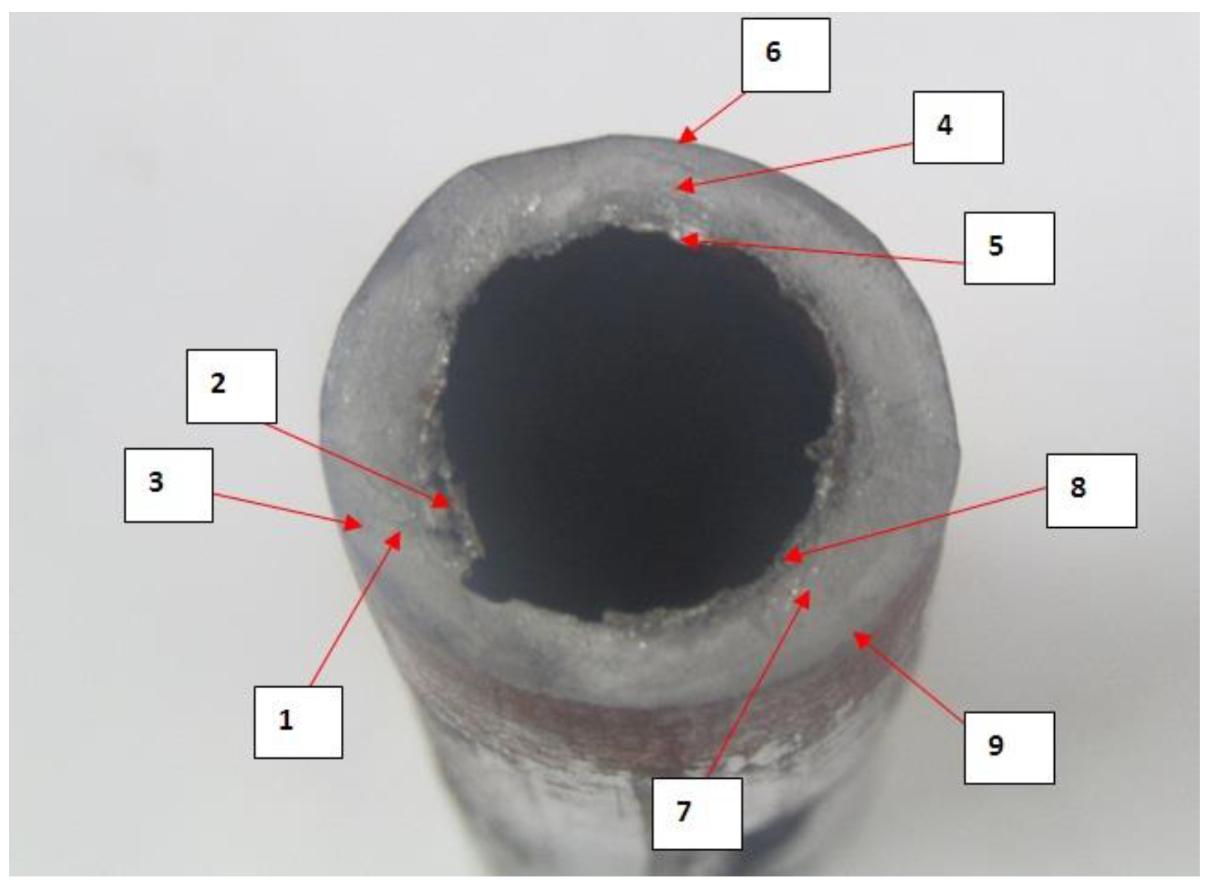
3.1. Visual Inspection of the MIAB Weld Sample

Welding trials carried out for the varying parameter ranges resulted in welds having differences in appearance. This difference was exhibited in the form of varying reinforcement heights, the width of HAZ, and bead formation. A uniform bead was achieved for a combination of the optimum range of pressure, current, and time duration as below:
  • Hydraulic Pressure—3.5–4 MPa;
  • Current Range—Stage I—150 A, Stage II—270 A;
  • Time Durations—Stage I—5 s, Stage II—0.3 s.
Samples that were welded with insufficient current and weld times showed irregularities like insufficient bonding and non-uniform reinforcement. For higher current and time respectively, the welding process caused excess loss of material with undesired melting of the weldments and deposition over the weld interface with large reinforcement height in the range of 2.5–4.5 mm. Metal and the impurities melted in such cases are observed to form a seed on the top of the weld surface, which settles at the bottom after being upset due to gravity. On visual inspection, such a weld response is seen in the form of a thin line joint between the weldments, with no reinforcement. The joint thus formed is a weak joint that indicates no fusion of surfaces due to quenched arc before the forging stage.

3.2. Chemical Composition of the MIAB Weld Sample

The results, Table 6, indicate the component percentages in line with the original material. This observation confirms that the MIAB weld process does not result in the formation of inter-metallics in the weldments. The thermal transformations that the material undergoes in the process impact the microstructure to attain different grades of precipitation from the austenite form. On attaining the respective forms based on the cooling rates, the material composition is observed to remain the same, as per the characteristics of any solid-state welding process.
There was no significant change in the chemical composition of the weld zone of the welded samples formed with the MIAB welding technique.

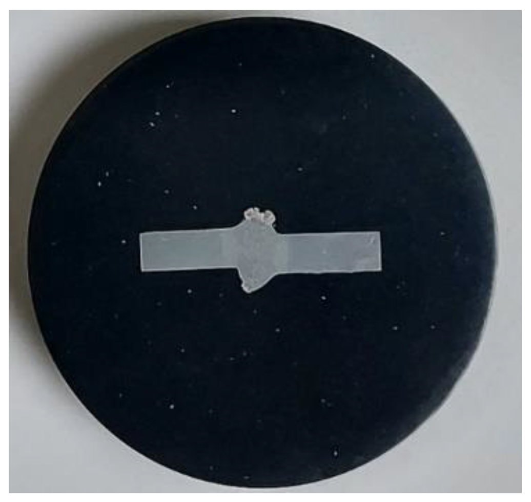
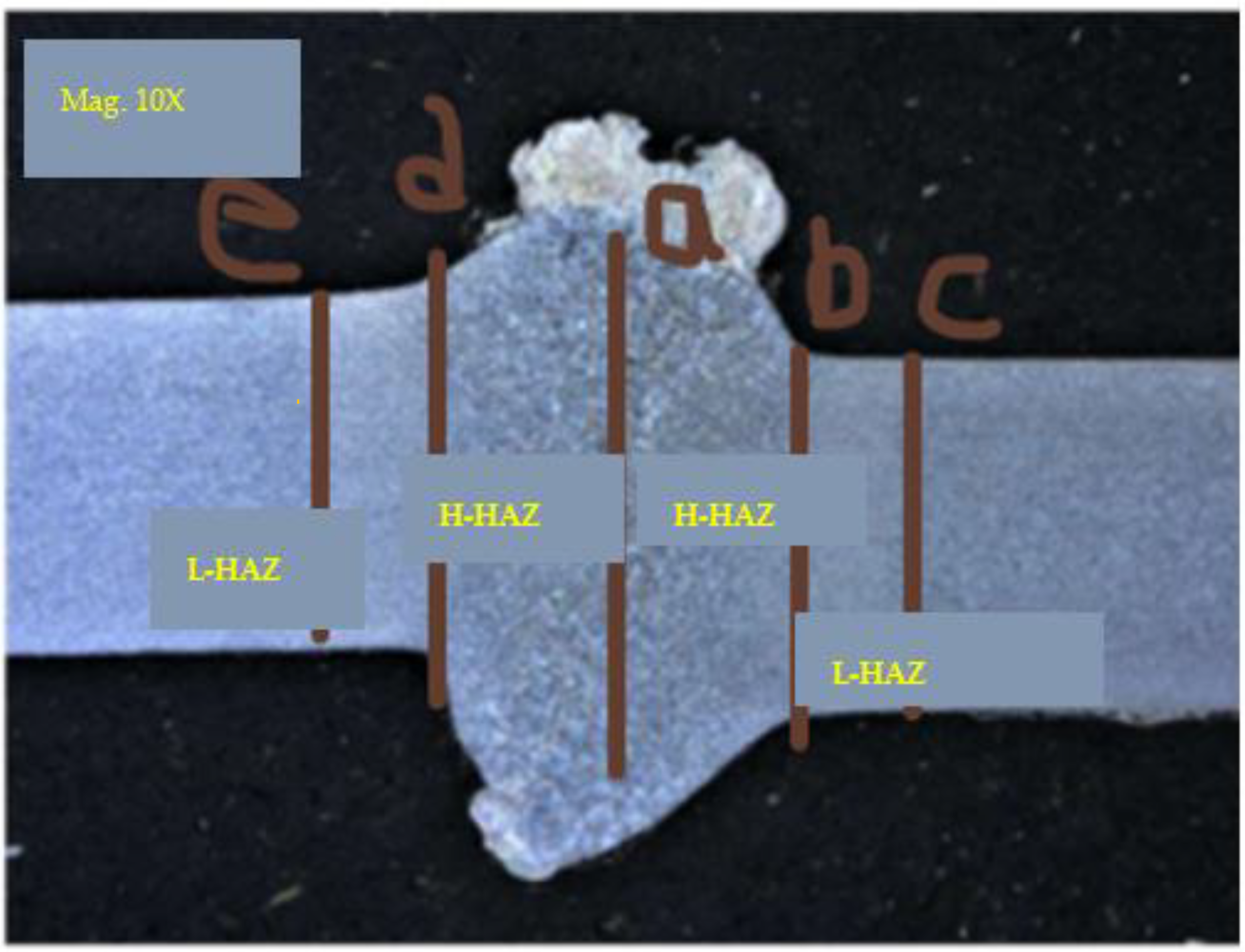
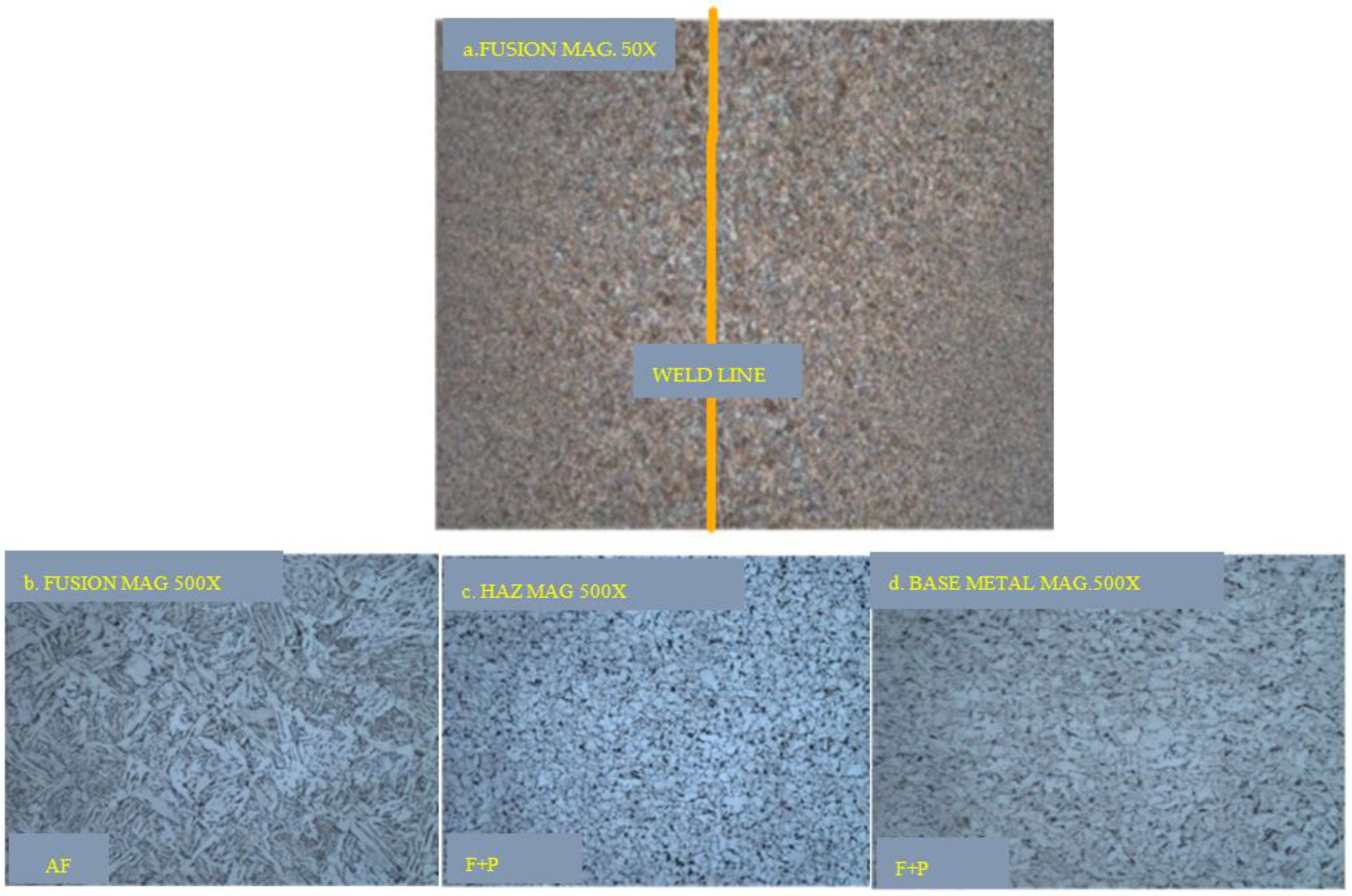
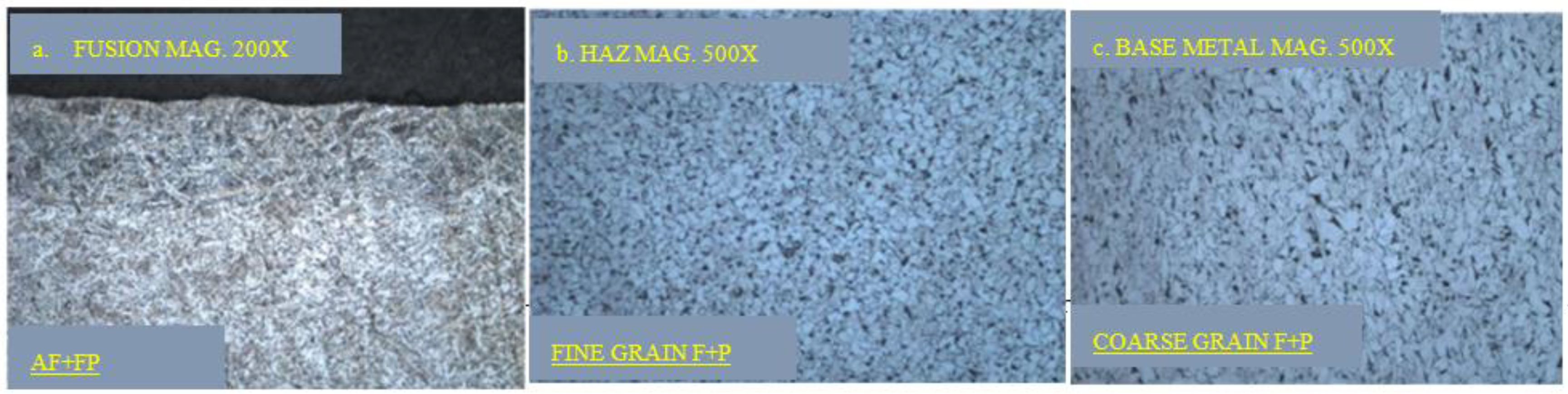
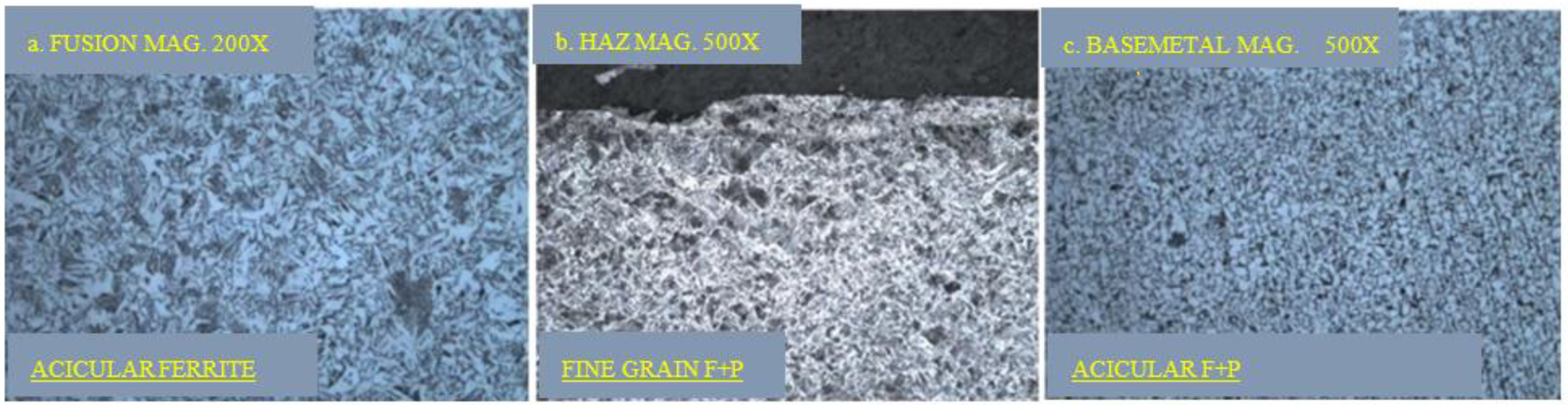
3.3. Macrostructural Characterisation of the MIAB Weld Sample

A macrostructure investigation of the weld samples was carried out on the etched sample, Figure 5. Macro images of the MS1018 weld samples are shown in Figure 6. The weld parts were clamped in the MIAB weld machine with an offset with respect to their axial placement. The misalignment of the weld parts seen in the macrostructure images is due to the offset in the tube placement. The desired weld characteristics were obtained even with the offset in clamping of the tubes. This proves the advantage of efficient formation of MIAB weld even with intentional or unintentional offset in the weld surfaces.
The welded samples show distinct solidification lines and regions marking the Thermo mechanically Affected Zones. The high amperage and the high-speed arc rotation cause high thermal gradients along the weld line and the variation in cooling rates results in the weld interface being surrounded by distinct TMAZs. The three samples did not show significant variation due to similar temperature rise caused by the arc heating achieved by the process parameters.
The low heat affected zone (L-HAZ) is the region having the minimum effect of the weld thermal cycle on the microstructure. The colder region i.e., the L-HAZ, acts as the substrate that initiates the solidification process and then it progresses towards the center weldline. The microstructure of the L-HAZ differs from that of the high heat affected zone (H-HAZ) because of the thermal effect at locations away from the weld interface. Low temperature in the L-HAZ region during welding results in increased grain size in this region as the grains experience recovery, recrystallization and minor grain growth [34].
Figure 7 shows the microstructural images of the weld region, base metal, and the HAZ for sample S1. The base material had an original grain size of approximately 2 µm, as attained after the cold rolling. Adjacent to this region in the heat affected zone, grains were quiaxed, with grain size increased with respect to base metal. The thermal cycle in the welding process caused changes in the microstructure. The arc moved from the external edges towards the internal edges due to the action of arc blow. The overheating region was located closer to the external edges of the tubes. The microstructure represented austenite boundaries over ferrite network and pearlite. Closer to the internal edges of the tube, HAZ was characterized by fine dispersed ferritic pearlitic structure with coarse grains. Microstructure of the fusion region on the internal edges of the tube indicated a ferritic pearlitic mix in the form of needles of Windmanstatten structure.
The microstructure did not reveal any micro-cracks or asperities in the fusion zone. Micro-examination in the weld zone revealed the formation of acicular ferrite. HAZ and the base metal exhibited fine grains of ferrite with pearlite. The difference in the two microstructures can be attributed to the deformation exerted in the form of the upset. Upset current and force caused deformation of the material and this process caused reduced growth of bainitic needles and retarding the molecular transformation at the weld interface. The heating stage caused the formation of overheated zones, which for this welding technique was nearly 30% of the weld section. Coarse grains formed due to overheating were expelled out in the upset phase. These expelled part formed the reinforcement, leaving the fine grain portion of faying surfaces to form the weld region.
Micro-structural images of sample S2, Figure 8 exhibits acicular ferrite with fine pearlite in the weld region, HAZ with fine grains of ferrite with pearlite and the base metal reveals its original form with coarse grains of ferrite with pearlite.
Sample S3 in its microstructure, Figure 9 shows acicular ferrite with fine pearlite in the weld zone and fine grains of ferrite and perlite in the HAZ. The base metal constitution has acicular ferrite with fine grains of pearlite.
Macro examination showed complete weld-fusion in the interface of the two tubes and significant penetration with no cracks and abnormalities. The HAZ formation was narrower in comparison to other solid-state welding processes. Dislocation of molecules in the microstructure results were due to the deformation of the two surfaces in the upset stage. Transformation of the microstructure with the rising temperature at the interface was retarded by the deformation caused in the upset stage by the application of short-duration high pressure of 40–45 bar. The weld interface, HAZ, and the base metal were observed to have differing microstructures based on the heat input, thermal gradient, and application of upset pressure. MIAB welding process resulted in narrow HAZ formation due to a combination of higher heat input and low weld cycle. HAZ was comprised of coarse grain structure due to continued heat dissipation. This was attributed to restricted heat source movement and low thermal gradient shift. The coarse grain region was expelled in the upset stage and the fusion zone had a fine grain structure due to uniform heating achieved with high-speed arc rotation [30].

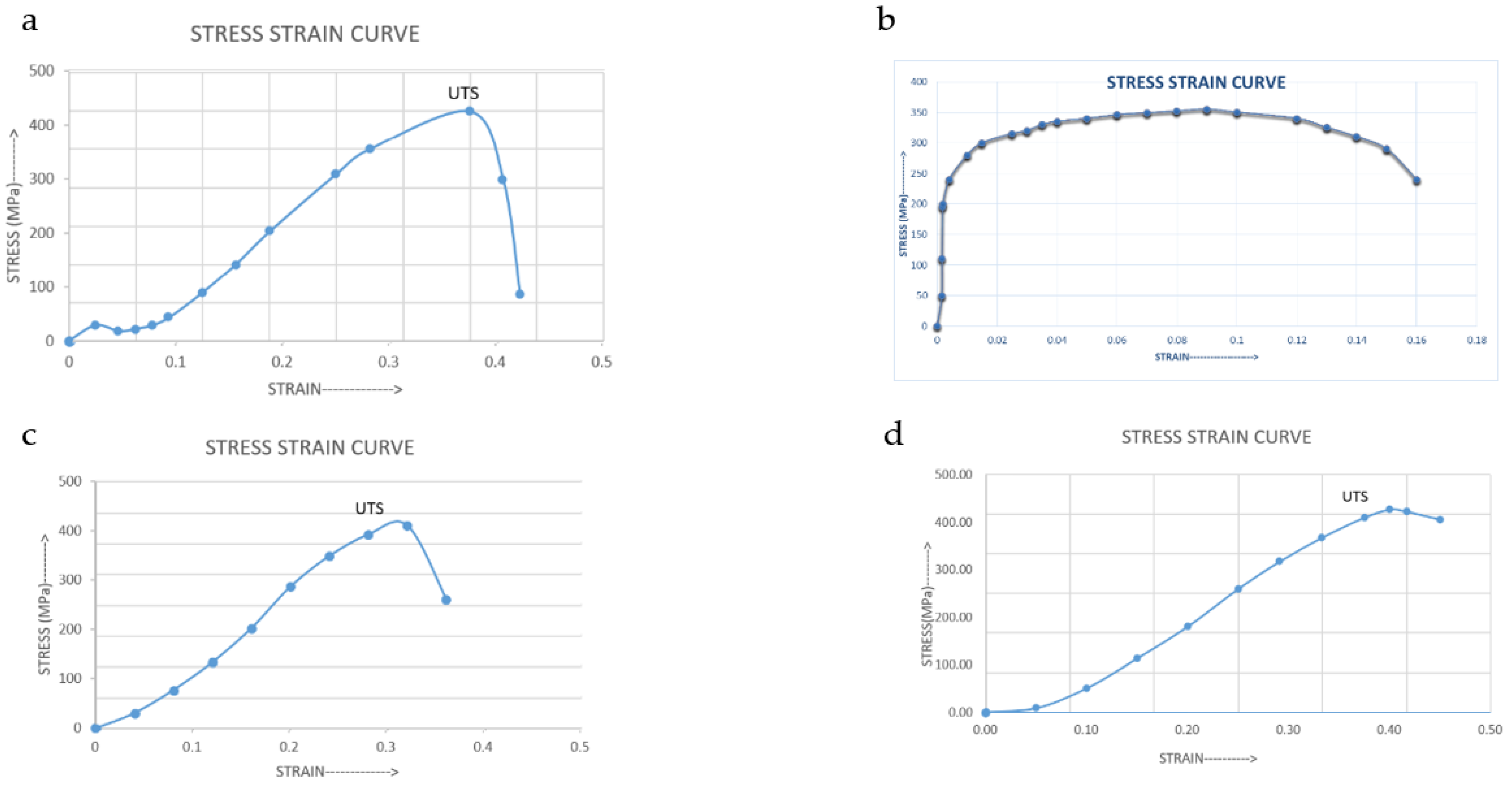
3.4. Tensile Test Result of the MIAB Weld Sample

The strength and ductility of the weld samples were analyzed with the tensile test. In the MIAB welding process, the faying surfaces change at the microstructural level due to a temperature gradient that changes with time, and they also experience deformation in the upset phase. The tensile test results of various samples are presented in Table 7. The stress -strain curves for the three samples and of the base metal are shown in Figure 10. These curves show the extrinsic properties of the weld sample like stiffness, work required for the failure of the weld, ultimate load, and displacement. Sample S1 and S2 failed at the base metal, indicating appropriate parametric levels. The failure at the weld section can be due to insufficient heat or inadequate cycle time to take the material to a solidus state which may result in the void formation or insufficient penetration. Failure at the base metal indicates higher strength of the weld interface which projects the merit of the MIAB welding process.
Sample S3 had tubes with end-to-end butt welds (W1, W2) with the same parameter values that were also tested for tensile properties to assess the process repeatability.
Sample S3 having two weld joints, failed at the weld interface for weld 1 (W1) and the weld 2 (W2) was intact at 448 MPa. These samples are welded with the same parameter values:
  • Arc current—158 A,
  • an upset current of 270 A,
  • with an arc heating time of 5 s,
  • upset time of 0.3 s.
These samples had acceptable weld formation as per the visual inspection. When the W1 weld failed, the tensile test for W2 weld could not be determined as the clamping stiffness was lost. The tensile load that fractured W1, did not cause fracture at W2, emphasizing the higher strength. The difference in the two tensile test results with the same parameters illustrates the limitations in the reproducibility of the process during the preliminary trials. The difference in results could also be attributed to the clamping position which causes varying load orientation.
These tests are a way of mapping the variation of mechanical properties across the weld. Lower arc current samples indicate lower weld strength at the weld interface due to incomplete fusion of the weldments. While combinations of higher current and time causing excessive heating of the surface may result in the melting of impurities present at the weld surface leading to excess loss of material or short-circuiting of the weld surface. A transverse tensile test was conducted for the weld material of a cross-sectional area of 234 sq. mm and gauge thickness of 3.11 mm under the ultimate tensile load of 117.8 kN. Tensile strength is impacted by the optimum selection of arc current and the upset current at appropriate pressure and weld time. Samples that failed at the weld indicate the formation of voids and improper softening at the faying surfaces due to low arc current. Failure at the base metal reveals good weld strength obtained with appropriate values of current and time.

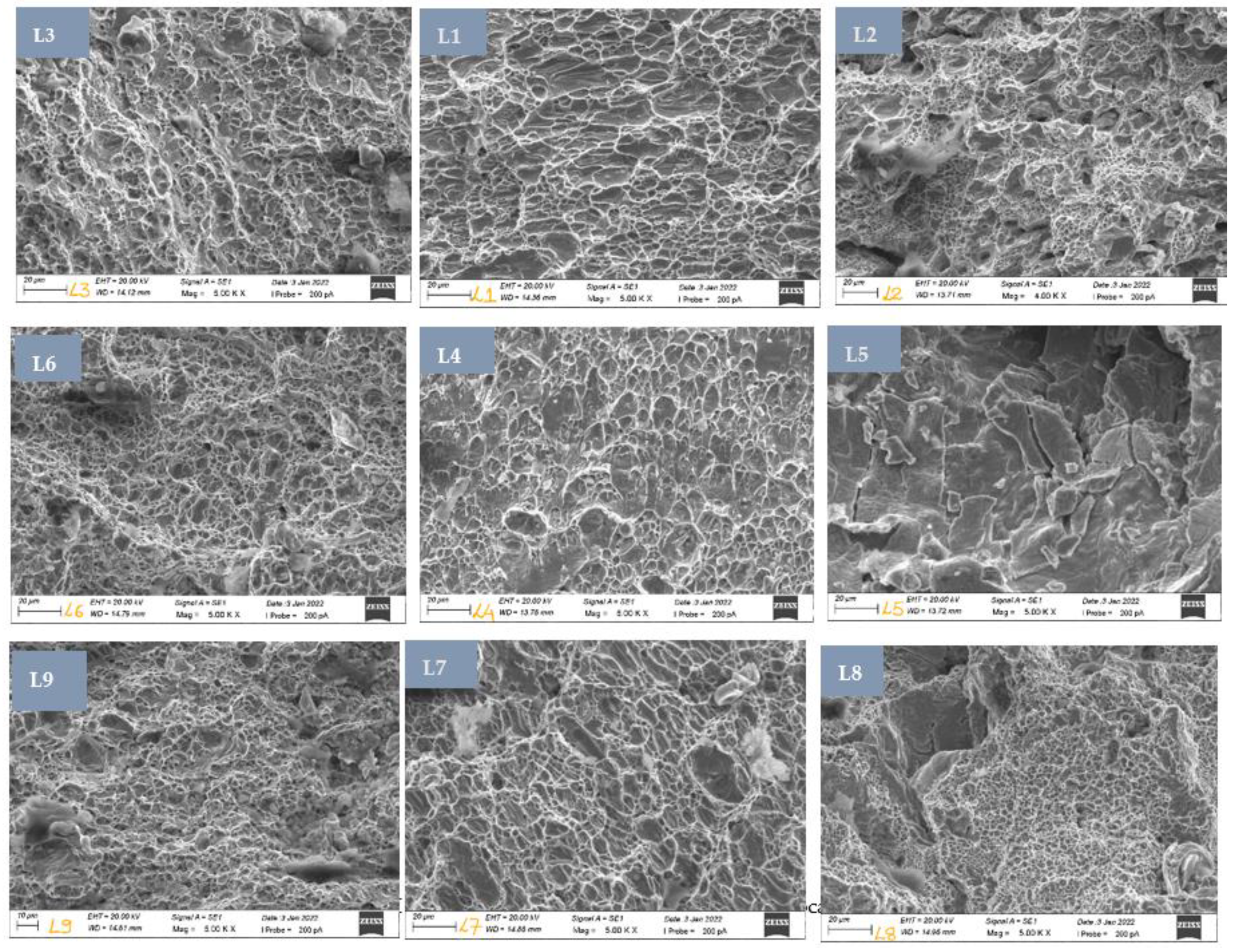
3.5. SEM Analysis of the MIAB Weld Sample

Sample S3-W1 that fractured at the weld was analyzed using Scanning Electron Microscopy (SEM) to identify the nature and cause of the fracture. Figure 11, shows the locations at which SEM images were captured in the failed weld sample.
SEM images captured at different locations, in Figure 12, show the microstructural transformations that the material undergoes during the process of MIAB welding.
Failure at the weld interface was observed to be caused due to both the brittle and ductile nature illustrated in the material. The fracture surface was intergranular exhibiting small and shallow dimples. Pores and voids were also observed in the fracture surface as seen in the SEM images. Rapid propagation of a crack with considerable deformation explains the dual form of fracture. Insufficient heat input due to lower arc current of shorter weld time can be attributed to being the reasons for this failure. Ductile fracture is explained by the increased strain rate at the joint due to the solid-state deformation at the tube edges and uneven heating of the surface. Also, a small crack length may lead to higher stress at the weldment resulting in a brittle form of fracture [32].
Locations 2, 5, 8 are at the internal edges of the fractured weld tubes. These regions are exposed to maximum heating and the upset effect as the arc is blown to the inner edges of the faying surfaces which results in the maximum impact of arc heating and deformation with the upset current. Location 5 indicates insufficient localized melting or plasticization of the surface resulting in weld failure along the inner diameter.
Locations 1, 4, 7 are the central regions of the tube thickness. Scan of surfaces from 1→2, 4→5, 7→8 show transition from ductile overload (dimples) to hot crack structure in the form of dendrites.
Locations 3, 6, 9 on the outer diameter, show oxides formation on the surface with small patches of non-plasticized regions in the weldments. Low arc current causes insufficient heating of the faying surfaces, resulting in voids due to non-uniform bounding or insufficient penetration.
SEM analysis of the fractured samples exhibited the microstructure deformations at various locations indicating the changes undergone with the thermal variations involved in the fast weld process. The microstructure at L5 has dimples that appear equiaxed, which indicated that the weld fracture was caused by tensile stress which was found to be normal to the fracture. Elongated dimples in the shear direction indicate joint fracture due to shear. The presence of large regions of dimples is an indicator of poor strength and low ductility. This fractography indicated river patterns, smooth areas, and certain cleavage steps. These may lead to trans-granular cleavage fracture during the tensile test. The weld fracture could be the result of a lower upset current causing incomplete expulsion of impurities and formation of the decarburized zone. This may also be a cause of the insufficient heat input leading to uneven melting and the formation of voids in the weld. For an efficient bond formation, the complete faying surface should experience uniform heating followed by cooling and complete recrystallization.

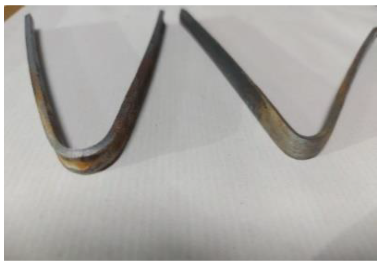
3.6. Bend Test Results of the MIAB Weld Sample

Root bend and face bend tests were conducted on the specimen with dimensions 300*10*3 mm and a mandrel diameter of 12 mm. The samples were subjected to bending of 180°, Figure 13 and were investigated for the development of cracks on the surface. The test showed no development of cracks in the face and the root bends of sample S1. The sample that failed at the tensile test, shows no cracks in the bend test indicating the ductile nature of the weld surface.

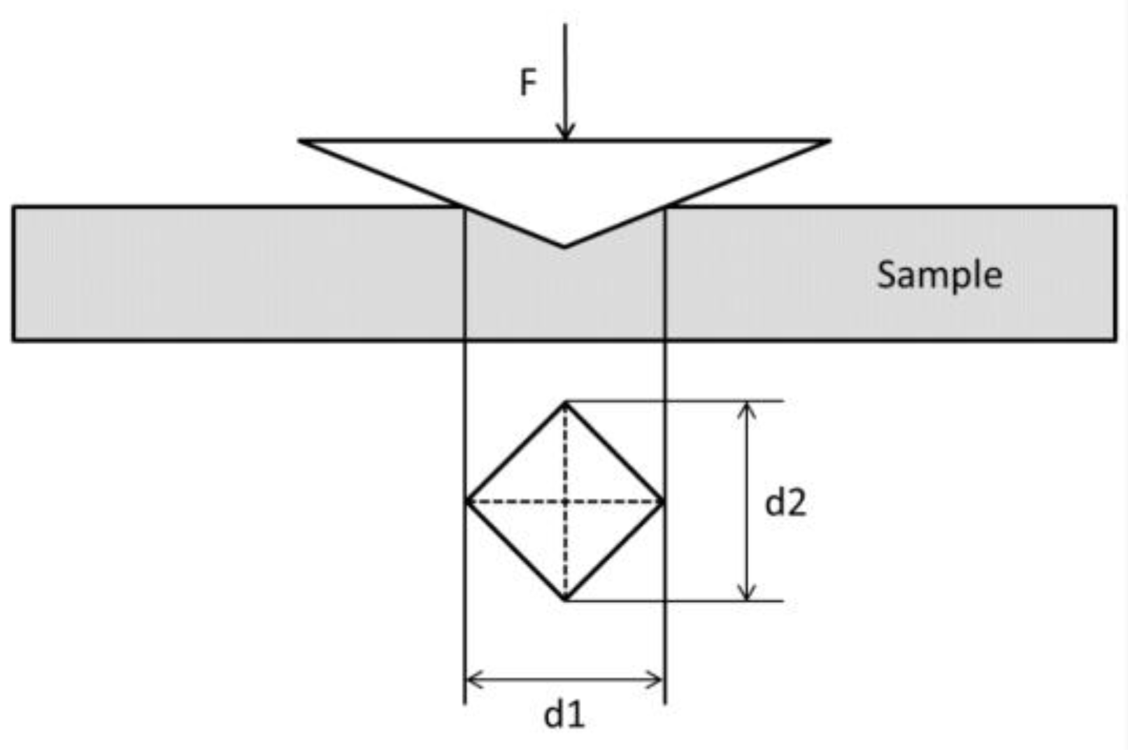
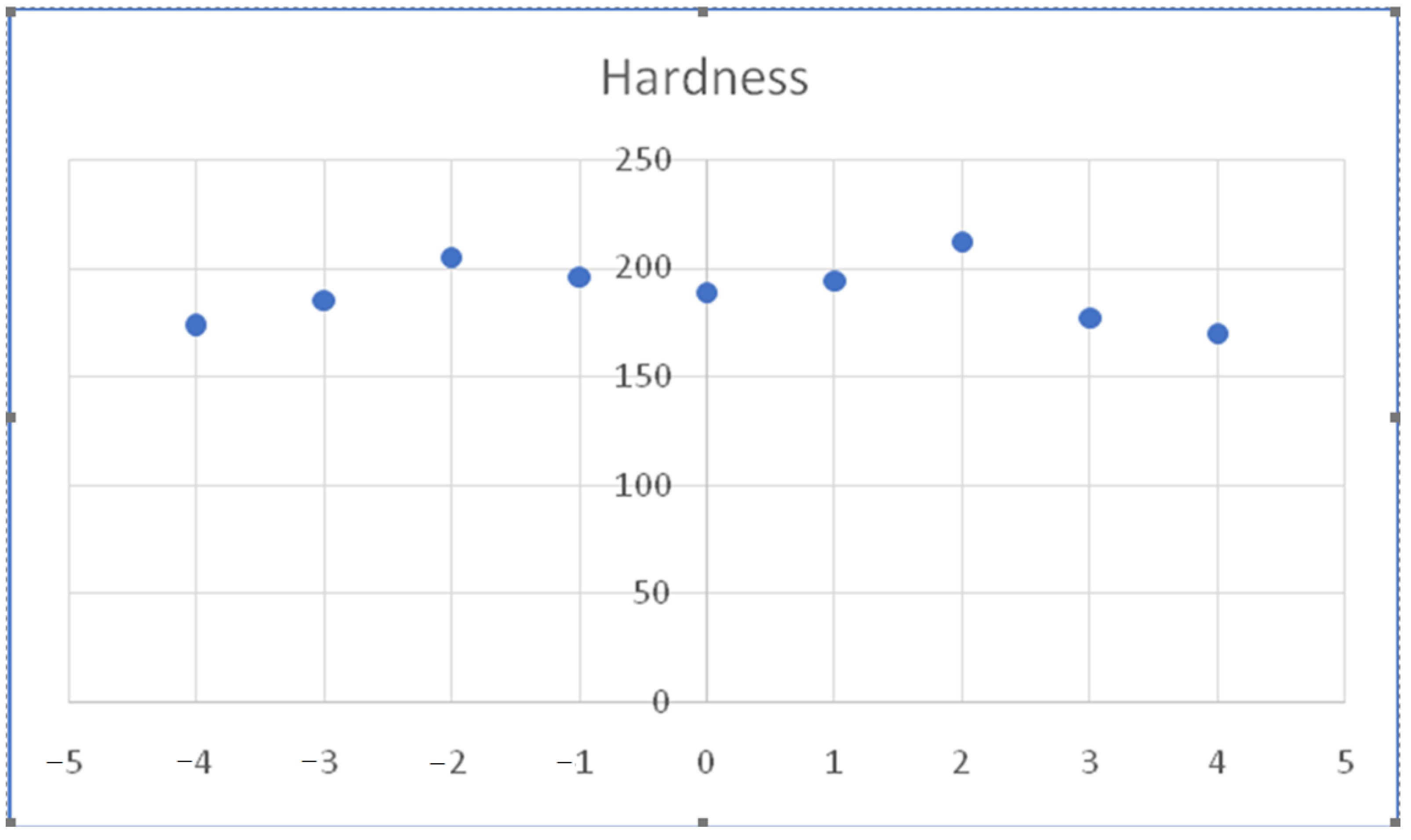
3.7. Hardness Testing of the MIAB Weld Sample

Hardness is the ability of the welds to resist plastic deformations made by making indentations. The samples need to be grinded, polished, and etched for proper HAZ identification before subjecting them to indentations in specific areas with a diamond indenter. The diagonal length of the indenter is measured with a microscope and the hardness number is determined by the ratio of applied load to the indentation surface area. Sample preparation for the test involved working on a micro-thickness section of the sample which is mounted over an epoxy or Bakelite mount. Hardness measurement is done based on the applied load and the measurement of indentation diagonals, Figure 14.
The average dimension of the indentation is given by:
d = d 1 + d 2 2  
Vicker’s Hardness number is then given by [35]:
H V = 0.102 2 F sin 136 2 ° d 2 = 0.1891 F d 2    
w h e r e   F a p p l i e d   i n d e n t a t i o n   f o r c e ,   d a v e r a g e   i n d e n t a t i o n   d i m e n s i o n
Hardness variations at distinct zones in the weldment are listed in Table 8. The hardness curve shows the variation in hardness for the test sample at increasing distances of 1mm from the weld, Figure 15. The retarded bainite growth causes reduced hardness in the weld region due to deformation caused to the microstructure in the upset phase.
The hardness characteristics of the weld significantly affect the welding behavior. During welding, metallurgical changes take place in the weldments due to rapid heating and cooling cycles. Hard microstructures comprising of low-temperature bainite are formed in the HAZ with rapid cooling after the upset stage in the welding process. Hardness tests detect such metallurgical changes in the weld pieces. The depth of penetration of the indenter is used to compute the hardness. Material along the weld experiences the maximum forging action and consequently the highest temperature gradient in the upset phase. The exposure to high temperatures in the weld region causes high dislocation density and bainite formation resulting in higher hardness at the weld [35]. The presence of impurities or voids can negatively impact the hardness of the material weld. The lowest hardness is found to appear in zones having columnar grains with large secondary dendrite arm spacing. This zone is described by a coarse structure and reduced carbon content in the alloy. Lower hardness in the weld zone indicates a lower volume fraction of bainite. The HAZ experiences grain coarsening during the upset phase and with the high cooling rate results in higher hardness than the weld. The composition of the steel in terms of alloy elements and carbon content governs the hardness of non-equilibrium steel phases. For future work, the MIAB technique could be compared with other welding technology. Also, artificial intelligence tools as well as swarm-based optimizers could be used to optimize and predict the weld characteristics [35,36,37,38].

4. Conclusions

MIAB welding process has several established advantages over other solid-state welding processes. Some of the advantageous features of this process are a short weld cycle, no rotation of parts, minimum loss of material, low residual stresses, no shielding gas requirement, and low energy requirements. Experimental trials were carried out on MS1018 tubes of 27 mm OD and 3 mm thickness to establish the parametric dependency for the MIAB weld process and the optimum process parameter values. Arc current, upset current, and weld duration are the key governing parameters of this process. Initial experiments were made with parameter values based on trial and error and previous technical reports. The appropriate value of weld pressure, arc current, and weld time were obtained with these trials. For the selected geometry of MS 1018 tubes, the operating range of process parameters has been obtained as listed in Table 9.
Samples were welded in the newly fabricated MIAB weld machine with the same value of stage I arc current. Differences in the weld formation were observed with the variation of upset current and the weld time. Visual inspection of the weld helped assess the parametric impact on the joint, HAZ, and flash expulsion which forms the weld bead. The testing and characterization of the weld sample revealed the following results:
  • The arc current for the two stages and respective time durations are maintained in the appropriate range based on the material properties, tube thickness, geometry, and tube gap. The mechanical test results confirm the operating range for the selected material and its geometry;
  • Maintaining the appropriate upset current in the upset duration is critical for the expulsion of the molten material along with any impurities and for the flash deposit of the plasticized material as the reinforcement at the weld interface. Microscopic images clearly indicate the reinforcement formed and the HAZ formations. Chemical analysis of the weld surface indicates properties to be the same as the base metal, indicating no formation of intermetallic;
  • However, on maintaining these current and time values, the weld formed may have variations which can be attributed to weld surface irregularities or the variations in upset pressure and the rate of application of pressure, magnetic properties of the AlNiCo or ferrous magnets and the tube gap length;
  • Particularly insufficient heat input leads to uneven localized melting and the formation of voids in the weld. This would not allow the complete expulsion of impurities, resulting in the formation of the decarburized zone at the weld interface. This is indicated in the phase transformations observed in the SEM image analysis;
  • Further research in this field must focus on minimizing the variable factors influencing the weld characteristics with the aim to get reproducible, reliable weld characteristics on every iteration.
MIAB welding has been observed to retain the original base metal properties in the welded region. Characteristics of some grades of steel enable their utility in high-pressure applications like boilers, submarines, automobile parts, etc. The experimental and testing observations will be significant for arriving at parametric dependencies and for framing standards and codes for this relatively new welding process. The experimental trials carried out have helped to arrive at the operating ranges of process parameters. The observations made as part of this work and further research will help project the MIAB weld process as a preferred method of welding ferrous tubes and pipes over friction, flash butt, and induction pressure welding.

Author Contributions

Conceptualization, M.C. and A.V.S.; methodology, M.Y.T.; soft-ware, S.A.S.; validation, V.K., S.A.S., S.R. and A.A.K.S.; formal analysis, E.S.; investigation, M.F.; resources, M.F.; data curation, A.H.E.; writing—original draft preparation, A.H.E., V.K., S.A.S., S.R. and A.A.K.S.; writing—review and editing, V.K., S.A.S. and A.A.K.S.; visualization, A.H.E.; supervision, M.C.; project administration, M.Y.T., A.V.S., M.C. and A.A.K.S.; funding acquisition, V.K., S.A.S. and A.A.K.S. All authors have read and agreed to the published version of the manuscript.

Funding

The authors would like to thank Department of Science and Technology (DST), Government of India for sponsoring this research study under Advanced Manufacturing Technology, Scheme. (Ref: DST/TDT/AMT/2017/228).

Institutional Review Board Statement

Not applicable.

Informed Consent Statement

Not applicable.

Data Availability Statement

Not applicable.

Conflicts of Interest

The authors declare no conflict of interest.

References

  1. Vendan, S.A.; Manoharan, S.; Buvanashekaran, G.; Nagamani, C. Magnetically Impelled Arc Butt Welding of alloy steel tubes in boilers—Establishment of parameter window. Mechatronics 2011, 21, 30–37. [Google Scholar] [CrossRef]
  2. Kachinskiy, V.S.; Krivenko, V.G.; Ignatenko, V.Y. Magnetically Impelled Arc Butt Welding of Hollow and Solid Parts. Weld. World 2002, 46, 49–56. [Google Scholar] [CrossRef]
  3. Vendan, S.A.; Manoharan, S.; Buvanashekaran, G.; Nagamani, C. Development of a MIAB welding module and experimental analysis of rotational behavior of arc—Simulation of electromagnetic force distribution during MIAB welding of steel pipes using finite element analysis. Int. J. Adv. Manuf. Technol. 2009, 43, 1144–1156. [Google Scholar] [CrossRef]
  4. Takagi, K.; Arakida, F.; Miyamori, H.; Ozawa, M. Arc rotating phenomena in Rotating Arc Butt Welding of steel pipes. Q. J. Jpn. Weld. Soc. 1986, 4, 305–311. [Google Scholar] [CrossRef] [Green Version]
  5. Vendan, S.A.; Thangadurai, V.; Vasudevan, A.; Kumar, A.S. Investigations on temperature distribution during revolutionary and zigzag movement of arc in magnetically impelled arc butt welding of tubes. Int. J. Appl. Electromagn. Mech. 2014, 46, 155–163. [Google Scholar] [CrossRef]
  6. Taneko, A.; Arakida, F.; Takagi, K. Analysis of arc rotation velocity in magnetically impelled arc butt welding. Weld. Int. 1987, 1, 247–253. [Google Scholar] [CrossRef]
  7. Sato, T.; Katayama, J.; Ioka, S.; Otani, M. An experimental study of rotational behaviour of the arc during magnetically impelled arc butt welding. Weld. Int. 1991, 5, 5–10. [Google Scholar] [CrossRef]
  8. Li, J.; Shrestha, S.L.; Long, Y.; Zhijun, L.; Xintai, Z. The formation of eutectic phases and hot cracks in one Ni–Mo–Cr superalloy. Mater. Des. 2016, 93, 324–333. [Google Scholar] [CrossRef]
  9. Deng, Y.; Zhang, J.; Jiao, K. Viscosity measurement and prediction model of molten iron. Ironmak. Steelmak. 2017, 45, 773–777. [Google Scholar] [CrossRef]
  10. Sivasankari, R.; Balusamy, V.; Venkateswaran, P.; Buvanashekaran, G.; Kumar, K.G. Characterization of magnetically impelled arc butt welded T11 tubes for high pressure applications. Def. Technol. 2015, 11, 244–254. [Google Scholar] [CrossRef]
  11. Kim, J.-W.; Choi, D.-H. A study on the numerical analysis of magnetic flux density by a solenoid for magnetically impelled arc butt welding. Proc. Inst. Mech. Eng. Part B J. Eng. Manuf. 2003, 217, 1401–1407. [Google Scholar] [CrossRef]
  12. Vendan, S.A.; Manoharan, S.; Buvanashekaran, G.; Nagamani, C. Magnetic flux distribution modelling of magnetically-impelled arc butt-welding of steel tubes using finite-element analysis. Proc. Inst. Mech. Eng. Part C J. Mech. Eng. Sci. 2008, 222, 1783–1790. [Google Scholar] [CrossRef]
  13. Vendan, S.A.; Manoharan, S.; Nagamani, C.; Buvanashekaran, G.; Subbiah, A.V. Experimental and statistical analysis of impact of various parameters on arc rotation in miab welding process by developing a laboratory module. Exp. Technol. 2010, 34, 40–48. [Google Scholar] [CrossRef]
  14. Vendan, S.A.; Manoharan, S.; Buvanashekaran, G.; Nagamani, C. Some studies on the electromagnetic aspects governing the magnetically impelled arcs through experimentation, finite element simulation and statistical analysis. Int. J. Appl. Electromagn. Mech. 2009, 31, 113–126. [Google Scholar] [CrossRef]
  15. Norrish, J.; Cuiuri, D.; Hossain, M. Modelling and simulation of the Magnetically Impelled Arc Butt (MIAB) process for transmission pipeline applications. In Proceedings of the International Pipeline Integrity Conference Australia, Sydney, Australia, 9 March 2005. [Google Scholar]
  16. Piwowarczyk, T.; Korzeniowski, M.; Ambroziak, A.; Kowal, T.; Rutka, R.; Karolewski, M. Effect of Pipe Face Preparation on the Quality of Magnetically Impelled Arc Welded Joints. Biul. Inst. Spaw. 2016, 60, 111–119. [Google Scholar] [CrossRef] [Green Version]
  17. Vendan, S.A.; Manoharan, S.; Buvanashekaran, G.; Nagamani, C. Simulation of Magnetic Flux Distribution for Magnetically Impelled Arc Butt Welding of Steel Tubes. Multidiscip. Model. Mater. Struct. 2009, 5, 229–234. [Google Scholar] [CrossRef]
  18. Sk, A.K.; Khan, N. An Experimental Investigation of Magnetically Impelled Arc Butt Welding of Pipes: A Review. Int. J. Curr. Eng. Technol. 2018. [Google Scholar] [CrossRef] [Green Version]
  19. Phillips, D.H. Magnetically Impelled Arc Butt (MIAB) Welding of Chromium-Plated Steel Tubular Components Utilizing Arc Voltage Monitoring Techniques. Ph.D. Thesis, The Ohio State University, Columbus, OH, USA, 2008. [Google Scholar]
  20. Panda, B.N.; Vendan, S.A.; Garg, A. Experimental- and numerical-based studies for magnetically impelled arc butt welding of T11 chromium alloy tubes. Int. J. Adv. Manuf. Technol. 2017, 88, 3499–3506. [Google Scholar] [CrossRef]
  21. Sedighi, M.; Mosayebnezhad, J. The influence of process parameters on the distribution of residual stresses in magnetically impelled arc welded joints. Proc. Inst. Mech. Eng. Part C J. Mech. Eng. Sci. 2019, 233, 3936–3949. [Google Scholar] [CrossRef]
  22. Vignesh, S.; Babu, P.D.; Venkatesh, V.P.; Vinoth, S.M.; Marimuthu, P. Experimental Investigations on Magnetically Impelled Arc Butt Welded T91 Steel Tubes. Trans. Indian Inst. Met. 2017, 70, 741–748. [Google Scholar] [CrossRef]
  23. Kumar, S.R.; Ravishankar, B.; Vijay, M. Prediction and analysis of magnetically impelled arc butt welded dissimilar metal. Mater. Today Proc. 2019, 27, 2037–2041. [Google Scholar] [CrossRef]
  24. Dhivyasri, G.; Rahul, S.; Kavitha, P.; Vendan, S.A.; Kumar, K.R.; Gao, L.; Garg, A. Dynamic control of welding current and welding time to investigate ultimate tensile strength of miab welded T11 tubes. J. Manuf. Process. 2018, 32, 564–581. [Google Scholar] [CrossRef]
  25. Iordachescu, D.; Georgescu, B.; Miranda, R.; Ruiz-Hervias, J.; Ocaña, J. Technological windows for MIAB welding of tubes featuring original longitudinal magnetization system with peripheral solenoids. J. Mater. Process. Technol. 2010, 210, 951–960. [Google Scholar] [CrossRef]
  26. Fletcher, L.; Stecher, G.; Stubbs, C.; Norrish, J.; Cuiuri, D.; Moscrop, J. MIAB welding of oil and gas pipelines. In Proceedings of the International Pipeline Conference, Calgary, AB, Canada, 26 September 2006; pp. 643–650. [Google Scholar]
  27. Kuchuk-Yatsenko, S.I.; Kachinsky, V.S.; Ignatenko, V.Y.; Goncharenko, E.I.; Koval, M.P. Magnetically-impelled arc butt welding of parts of automobile range of products. Paton Weld. J. 2010, 6, 28–31. [Google Scholar]
  28. Faes, K.; Kachinskiy, V.S.; Silva, R.G.N.; Kuchuk-Yatsenko, S.I. Magnetically impelled arc butt welding of high-strength steel tubular parts of hydraulic cylinder. Weld. Mater. Test. 2020, 3. [Google Scholar]
  29. Vendan, S.A.; Mundla, S.R.; Buvanashekaran, G. Feasibility of Magnetically Impelled Arc Butt (MIAB) Welding of High-Thickness Tubes for Pressure Parts. Mater. Manuf. Process. 2011, 27, 573–579. [Google Scholar] [CrossRef]
  30. Vendan, S.A.; Manoharan, S.; Nagamani, C. MIAB welding of alloy steel tubes in pressure parts: Metallurgical characterization and non destructive testing. J. Manuf. Process. 2012, 14, 82–88. [Google Scholar] [CrossRef]
  31. Vendan, S.A.; Manoharan, S.; Buvanashekaran, G.; Nagamani, C. Strength assessment using destructive testing on MIAB welded alloy steel tubes and subsequent techno-economical evaluation. J. Manuf. Process. 2012, 14, 328–335. [Google Scholar] [CrossRef]
  32. Sivasankari, R.; Balusamy, V.; Venkateswaran, P.R.; Buvanashekaran, G.; Kumar, K.G. Light Band Zone Formation and its Influence on Properties of Magnetically Impelled Arc Butt (MIAB) Welded Carbon Steel Tubes. Trans. Indian Inst. Met. 2017, 71, 351–360. [Google Scholar] [CrossRef]
  33. Kustroń, P.; Korzeniowski, M.; Piwowarczyk, T.; Sokołowski, P. Application of Immersion Ultrasonic Testing for Non-Contact Quality Evaluation of Magnetically Impelled Arc Butt Welded Drive Shafts of Motor Vehicles. Adv. Automob. Eng. 2017, 2017, 59380187. [Google Scholar] [CrossRef] [Green Version]
  34. Shen, J.; Gonçalves, R.; Choi, Y.T.; Lopes, J.; Yang, J.; Schell, N.; Kim, H.S.; Oliveira, J. Microstructure and mechanical properties of gas metal arc welded CoCrFeMnNi joints using a 410 stainless steel filler metal. Mater. Sci. Eng. A 2022, 857, 144025. [Google Scholar] [CrossRef]
  35. Medeiros, E.E.; Dias, A.M.d.S. Experimental and numerical analysis of Vickers hardness testing. Int. J. Res. Rev. Appl. Sci. 2013, 17, 9–18. [Google Scholar]
  36. AbuShanab, W.S.; Elaziz, M.A.; Ghandourah, E.I.; Moustafa, E.B.; Elsheikh, A.H. A new fine-tuned random vector functional link model using Hunger games search optimizer for modeling friction stir welding process of polymeric materials. J. Mater. Res. Technol. 2021, 14, 1482–1493. [Google Scholar] [CrossRef]
  37. Elsheikh, A. Bistable Morphing Composites for Energy-Harvesting Applications. Polymers 2022, 14, 1893. [Google Scholar] [CrossRef]
  38. Elsheikh, A.H.; Elaziz, M.A.; Vendan, A. Modeling ultrasonic welding of polymers using an optimized artificial intelligence model using a gradient-based optimizer. Weld. World 2021, 66, 27–44. [Google Scholar] [CrossRef]
Figure 1. MIAB weld process schematic indicating the placement of weld tubes, permanent magnets, and formation of the arc.
Metals 12 01965 g001
Figure 2. Four Stages in MIAB welding process: (a) Stage I; (b) Stage II; (c) Stage III; and (d) Stage IV.
Metals 12 01965 g002
Figure 4. Effect of Arc rotation on the faying surfaces. (Macroscopic Image has been captured with a 12 MP camera).
Metals 12 01965 g004
Figure 5. Sample Preparation for Microscopic Analysis.
Metals 12 01965 g005
Figure 6. Macro-Examination Image (10×) for Sample: Region a: Weld Interface, a–d & a–b: H-HAZ, d–e & b–c: L-HAZ.
Metals 12 01965 g006
Figure 7. Microscopic Images for Sample S1: (a) fusion region 50×; (b). fusion—500×; (c). HAZ—500×; and (d). Base metal—500×.
Metals 12 01965 g007
Figure 8. Microscopic Images for Sample S2: (a). Fusion region 200×, (b). HAZ—500×, (c). Base metal —500×.
Metals 12 01965 g008
Figure 9. Microscopic Images for sample S3: (a). Fusion region 200×, (b). HAZ—500× (c). Base metal —500×.
Metals 12 01965 g009
Figure 10. Stress-Strain Curve of Samples: (a)—Sample S1, (b)—Sample S2, (c)—Sample S3, (d)—Base Metal.
Metals 12 01965 g010
Figure 11. SEM LOCATIONS FOR THE SAMPLE S3-W1 1–9.
Metals 12 01965 g011
Figure 12. SEM images of fractured sample S3-W1 at the locations L1 to L9.
Metals 12 01965 g012
Figure 13. Root bend and Face bend test sample S1.
Metals 12 01965 g013
Figure 14. Hardness test schematic.
Metals 12 01965 g014
Figure 15. Sample S2 hardness variation at different locations with respect to distance from the weld.
Metals 12 01965 g015
Table 1. Current and Time Range for MS1018 tubes of 27 mm OD and 1.5 mm thickness in various phases of the MIAB welding process.
StageCurrent (A)Time (s)
I: Arc-Formation, Rotation, Heating140–1805–5.5
II: Upset Stage250–2700.3–0.4
Table 2. Chemical composition of the MS1018 weld samples.
ElementCSiMnPS
Wt%0.14–0.200.150.6–0.90.04 (max)0.05 (max)
Table 3. Observation table for varying arc current and upset current and other variables maintained constant.
TUBE OUTER DIAMETER—27 mm, HYDRAULIC PRESSURE—3–3.5 Mpa
SampleI1I2T1T2Spark GenerationArc RotationWeldingAvg.
Reinforcement
HAZ
115526550.3NONONO00
216027050.3NONONO00
315526550.3NONONO00
416027050.3NONONO00
Table 4. Observation table for varying arc current and upset current and other variables maintained constant as per Trial and Error. (All the images included in the table are macroscopic images that have been captured with a 12MP camera).
TUBE OUTER DIAMETER—27 mm, Hydraulic Pressure—4 MPa
SampleI1I2T1
(s)
T2
(s)
Spark GenerationArc RotationWeldingAvg. Reinforcement (mm)HAZ
(mm)
Remark
114525030.1NONONO--Inappropriate parameters for arc formation
214725030.1NONONO--
314725030.3NONONO--
415025030.3NONONO--
515525030.1NONONO--
615525550.3NONONO--
715525550.3YESYESNO
Metals 12 01965 i001
3.524Arc got created, rotation speed was insufficient for required heat generation
816027050.3YESYESYES
Metals 12 01965 i002
527Arc rotation with partial melting. Weld formation not proper
91552654.50.3YESYESYES
Metals 12 01965 i003
3.825Uniform reinforcement and no breakage on pressure striking
101602704.50.3YESYESYES
Metals 12 01965 i004
4.2527Weld formed, but broke on pressure striking
111702704.400.4YESYESYES
Metals 12 01965 i005
429Excess heating due to high arc current
121702754.750.5YESYESYES
Metals 12 01965 i006
4.9529Surface impurity melted before the metal. Can negatively impact the weld quality
131802805.00.5YESYESNO
Metals 12 01965 i007
--30Excess melting of the surface with high values of current and time
Table 5. Experimental Parameter Value. (All the images included in the table are macroscopic images that have been captured with a 12 MP camera).
SampleWelding Current (A)Upset Current (A)Weld Time (s)HAZ (mm)WeldVisual Observation
S11582654.8+0.318Metals 12 01965 i008Insufficient reinforcement
S21582655+0.317Metals 12 01965 i009Non-Uniform bead
S3-W1,W21582705+0.318Metals 12 01965 i010Good Reinforcement
Table 6. The material composition of the weld sample and the mechanical properties:.
ElementCSiMnPSYield Strength (MPa)Tensile Strength (MPa)Elongation (%)
Wt%0.0810.1430.8050.0150.00125848531
Table 7. Tensile Test Results.
SampleUltimate Tensile Load (kN)Tensile Strength (MPa)Test Result
S1117.8503Ductile Fracture at Base Metal
S2124.7491Ductile Fracture at Base Metal
S3-W1103.1448Ductile Fracture at Weld
S3-W2----No Failure at Weld
Table 8. Hardness test results.
RegionHardness Value (HV)
Location 1 (HV)Location 2 (HV)Location 3 (HV)Average HV
Weld189194196193
HAZ212205185200
BASE177174170174
Table 9. Operating range of process experiments as part of experimental observations.
Hydraulic Pressure (MPa)Nitrogen Accumulator Pressure (MPa)Arc Current—Stage I (A)Weld Time—Stage I (s)Arc Current—Stage II (A)Weld Time—Stage II (s)
3–3.52.8–3150–1705–5.5260–2800.3–0.5
Publisher’s Note: MDPI stays neutral with regard to jurisdictional claims in published maps and institutional affiliations.

