
Investigation of Microstructure and Mechanical Properties of the Repaired Precipitation-Strengthened Ni-Based Superalloy via Laser Melting Deposition

 ,
,
Abstract
:1. Introduction
2. Material and Methods
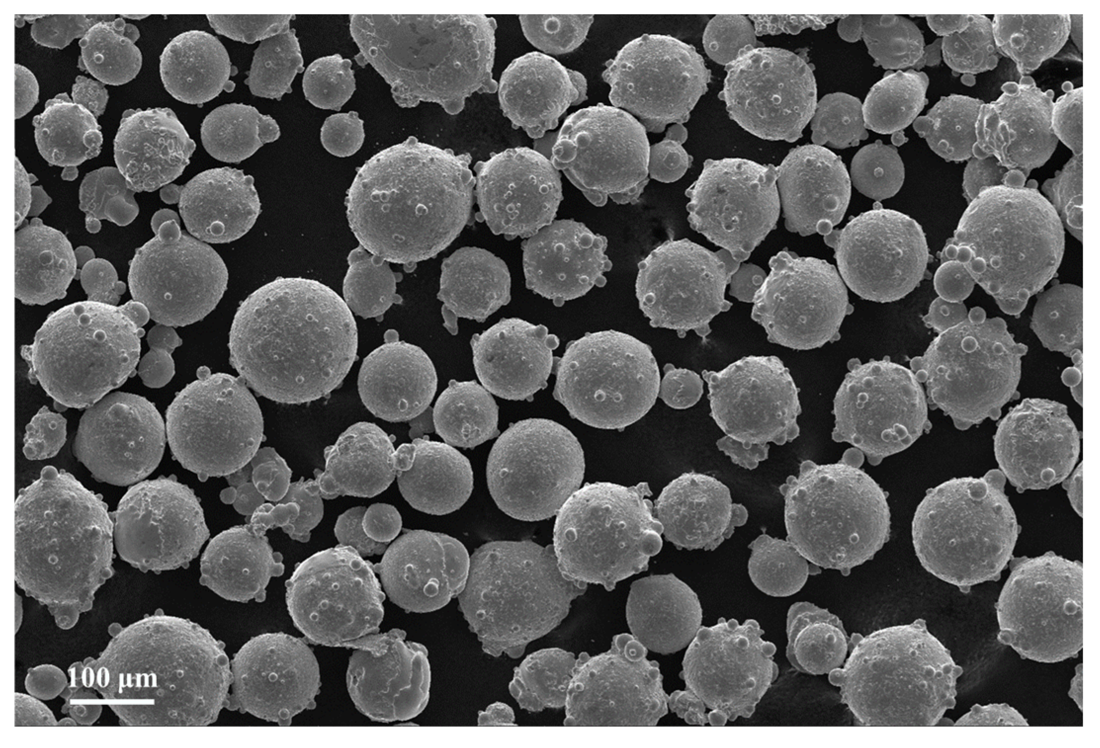
2.1. Materials
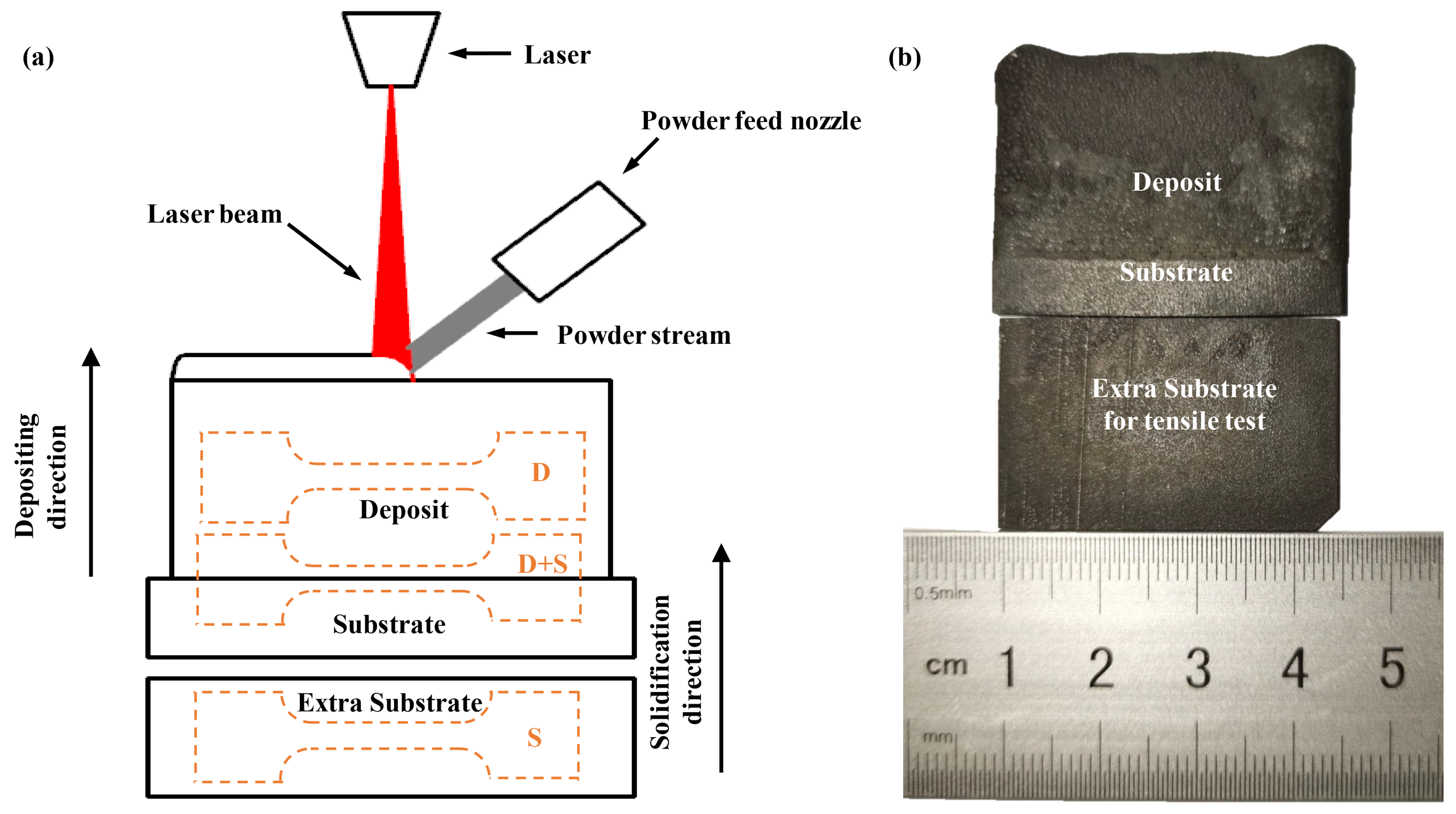
2.2. Repair Process
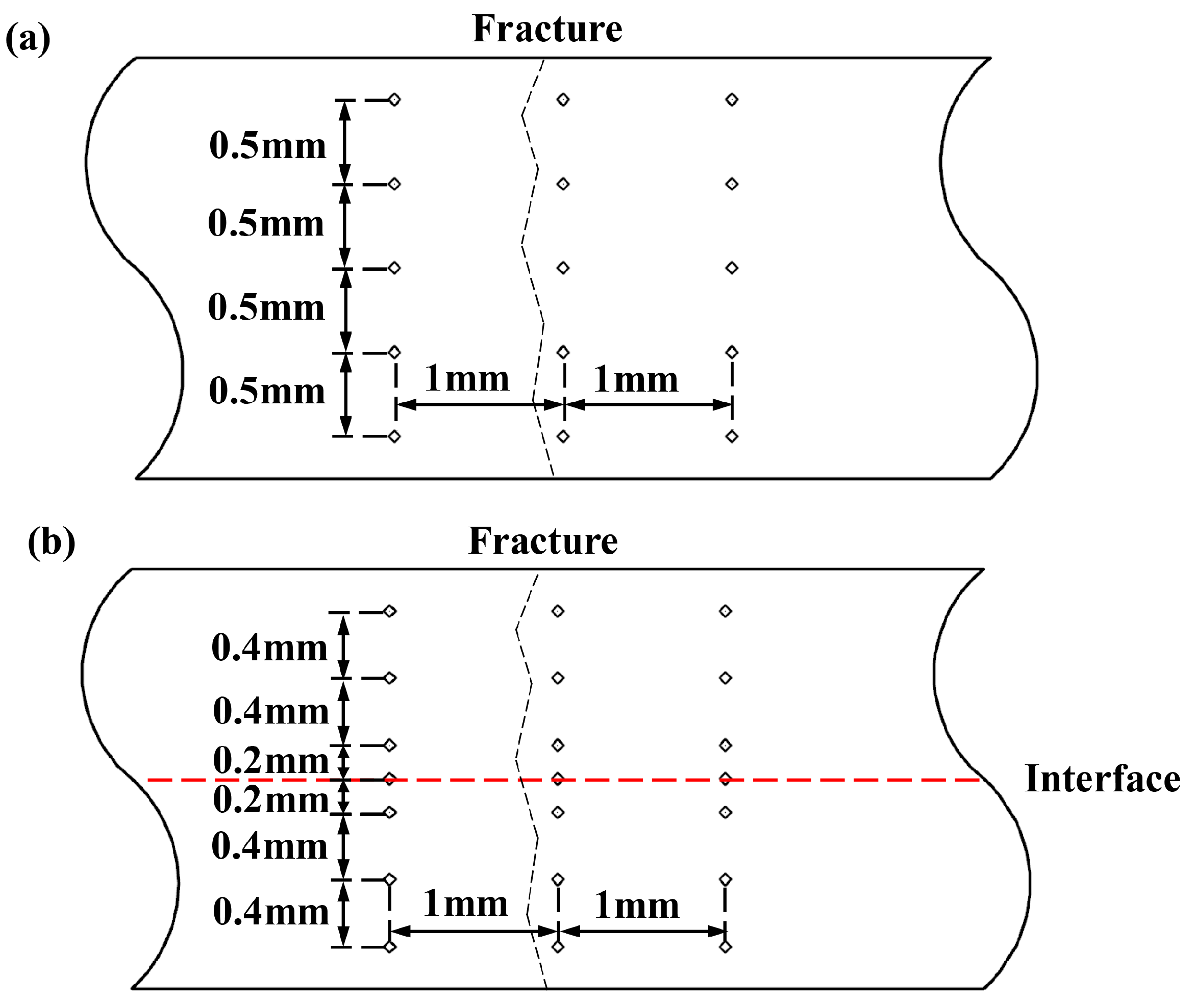
2.3. Microstructure Characterization and Tensile Test
3. Results
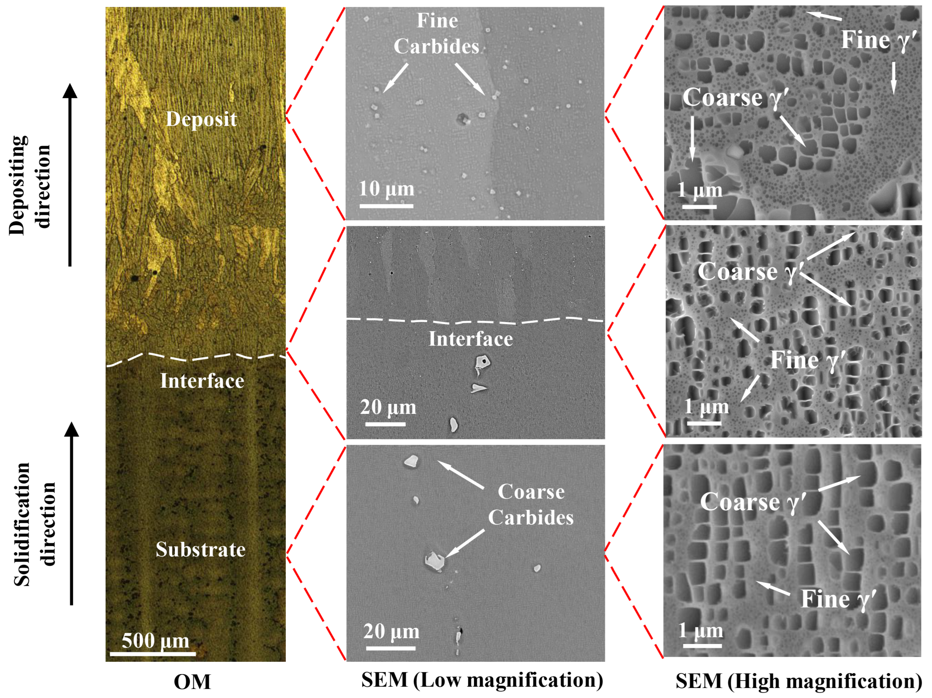
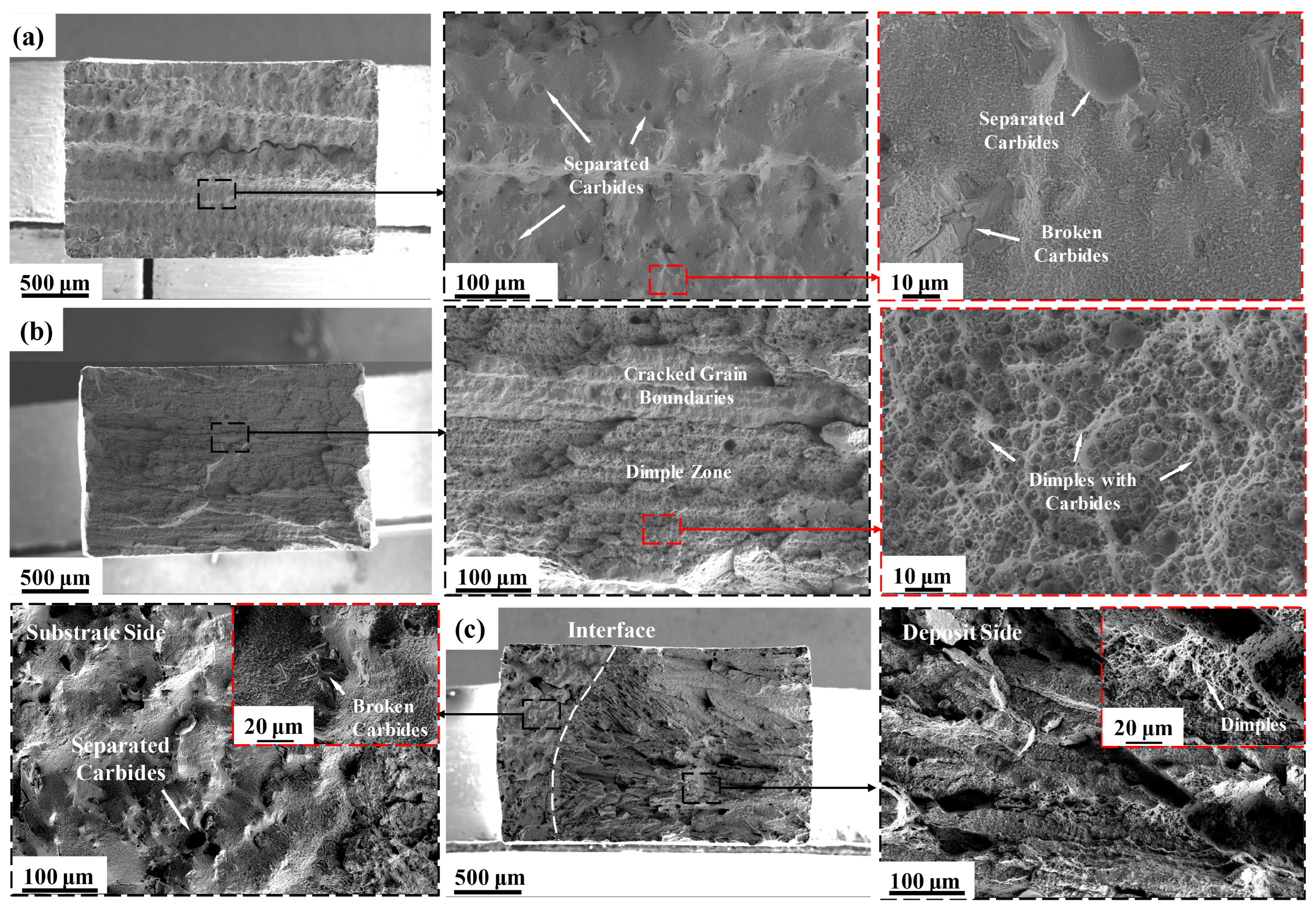
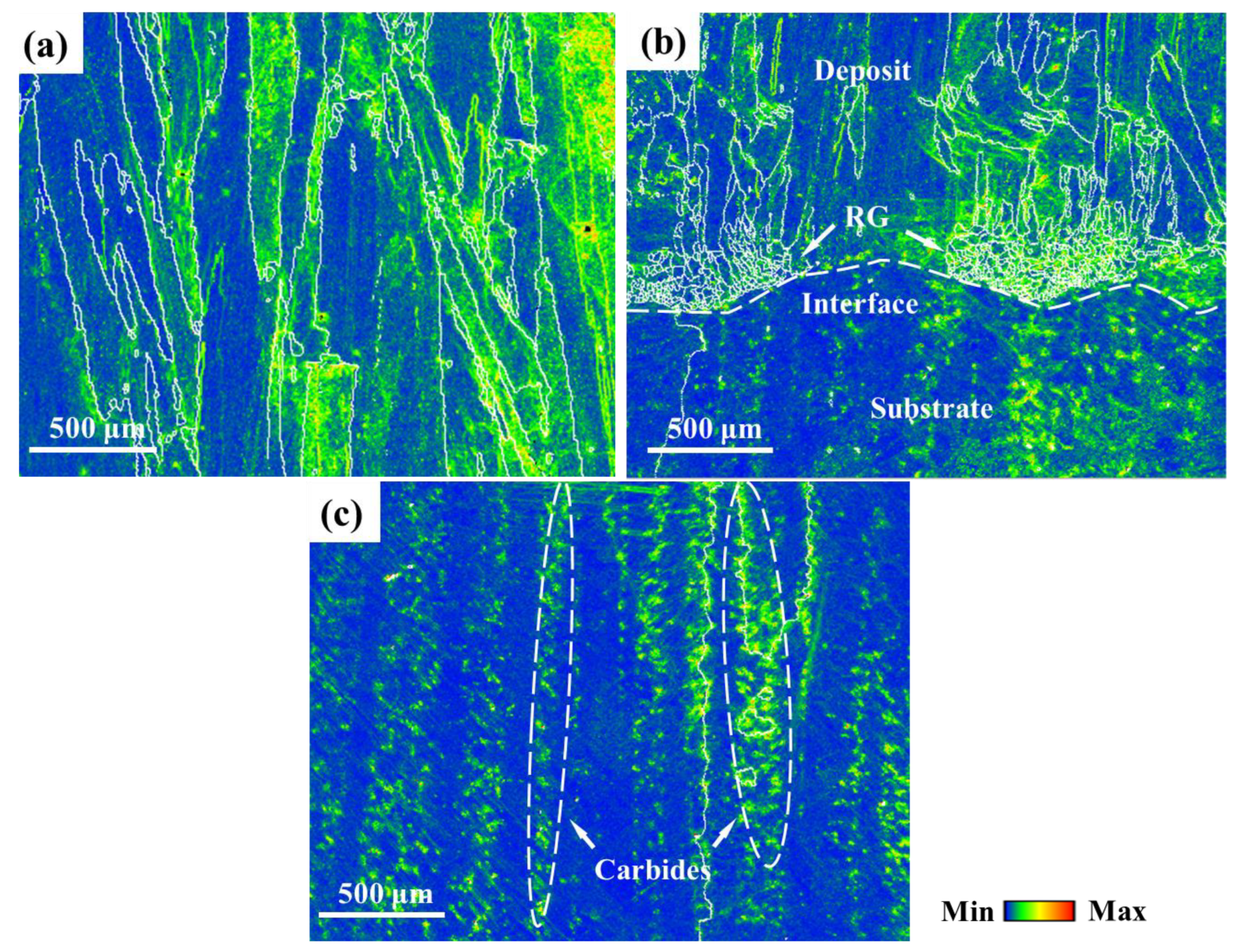
3.1. Microstructure
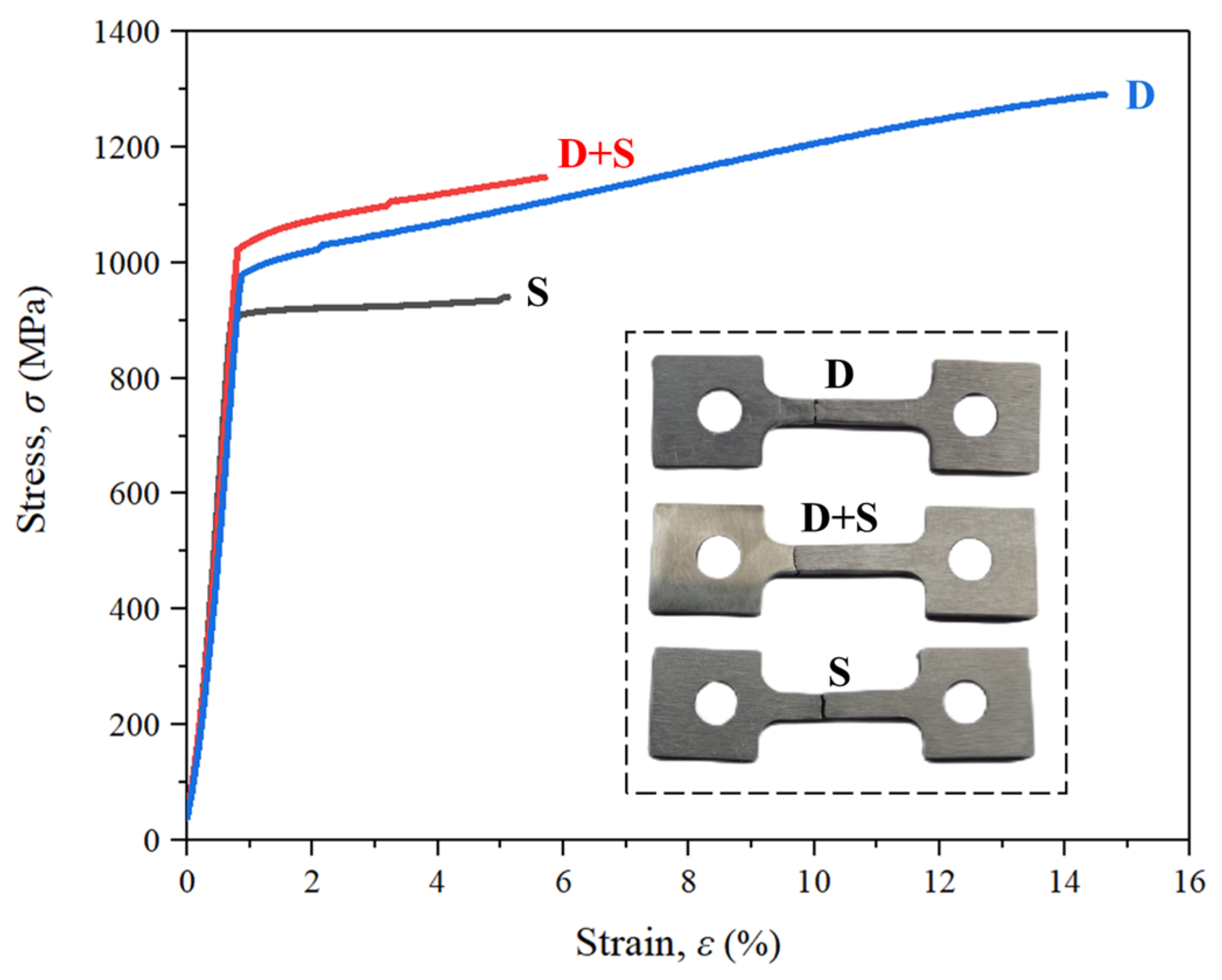
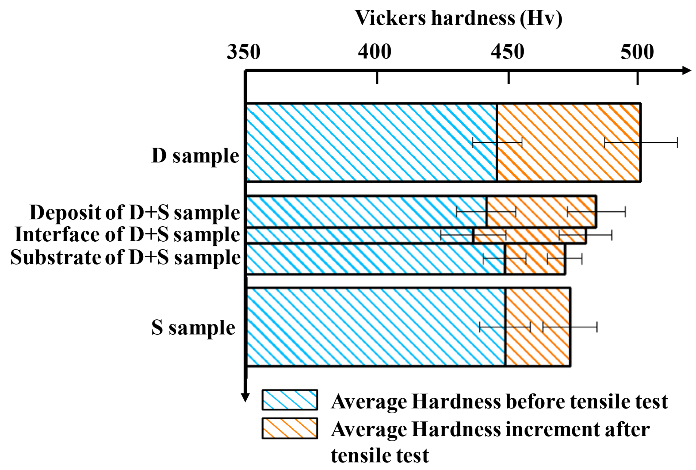
3.2. Mechanical Properties
4. Discussion
5. Conclusions
Author Contributions
Funding
Institutional Review Board Statement
Informed Consent Statement
Data Availability Statement
Conflicts of Interest
References
- Xu, R.; Li, Y.; Yu, H. Creep Behavior and Deformation Mechanism of a Third-Generation Single Crystal Ni-Based Superalloy at 980 °C. Metals 2023, 13, 1541. [Google Scholar] [CrossRef]
- Yan, W.-G.; Zeng, W.; Man, J.-X.; Qiao, D.; Zhang, Z.-X.; Bian, X.-D. Microstructure and mechanical properties of a directionally solidified superalloy DZ411 plate sample repaired by laser melting deposition. Mater. Sci. Eng. A 2023, 876, 145141. [Google Scholar] [CrossRef]
- Chen, J.; Chen, J.; Wang, Q.; Wu, Y.; Li, Q.; Xiao, C.; Hui, X. Mutation in TCP phases and superior stress rupture life led by W/Mo ratio in Ni-based single crystal superalloys. Mater. Lett. 2022, 312, 131656. [Google Scholar] [CrossRef]
- Yang, Q.; Xu, Z.; Li, L.; Li, P. Microstructure and Performance Research on Ceramic-Enhanced Inconel 718 Matrix Composite Using Laser Additive Manufacturing. Metals 2023, 13, 1525. [Google Scholar] [CrossRef]
- Wang, J.; Pan, Z.; Wang, Y.; Wang, L.; Su, L.; Cuiuri, D.; Zhao, Y.; Li, H. Evolution of crystallographic orientation, precipitation, phase transformation and mechanical properties realized by enhancing deposition current for dual-wire arc additive manufactured Ni-rich NiTi alloy. Addit. Manuf. 2020, 34, 101240. [Google Scholar] [CrossRef]
- Li, L.; Deceuster, A.; Zhang, C. Effect of Process Parameters on Pulsed-Laser Repair of a Directionally Solidified Superalloy. Met. Microstruct. Anal. 2012, 1, 92–98. [Google Scholar] [CrossRef]
- Moattari, M.; Shokrieh, M.M.; Moshayedi, H.; Kazempour-Liasi, H. Evaluations of residual stresses in repair welding of Ni-based IN939 superalloy. J. Therm. Stress. 2020, 43, 801–815. [Google Scholar] [CrossRef]
- Rush, M.T.; Colegrove, P.A.; Zhang, Z.; Broad, D. Liquation and post-weld heat treatment cracking in Rene 80 laser repair welds. J. Mater. Process. Technol. 2012, 212, 188–197. [Google Scholar] [CrossRef]
- Liu, G.; Du, D.; Wang, K.; Pu, Z.; Chang, B. Hot cracking behavior and mechanism of the IC10 directionally solidified superalloy during laser re-melting. Vacuum 2020, 181, 109563. [Google Scholar] [CrossRef]
- Bidron, G.; Doghri, A.; Malot, T.; Fournier-Dit-Chabert, F.; Thomas, M.; Peyre, P. Reduction of the hot cracking sensitivity of CM-247LC superalloy processed by laser cladding using induction preheating. J. Mater. Process. Technol. 2019, 277, 116461. [Google Scholar] [CrossRef]
- Griffiths, S.; Tabasi, H.G.; Ivas, T.; Maeder, X.; De Luca, A.; Zweiacker, K.; Wróbel, R.; Jhabvala, J.; Logé, R.; Leinenbach, C. Combining alloy and process modification for micro-crack mitigation in an additively manufactured Ni-base superalloy. Addit. Manuf. 2020, 36, 101443. [Google Scholar] [CrossRef]
- Guo, C.; Li, G.; Li, S.; Hu, X.; Lu, H.; Li, X.; Xu, Z.; Chen, Y.; Li, Q.; Lu, J.; et al. Additive manufacturing of Ni-based superalloys: Residual stress, mechanisms of crack formation and strategies for crack inhibition. Nano Mater. Sci. 2023, 5, 53–77. [Google Scholar] [CrossRef]
- Xu, J.; Ding, Y.; Gao, Y.; Wang, H.; Hu, Y.; Zhang, D. Grain refinement and crack inhibition of hard-to-weld Inconel 738 alloy by altering the scanning strategy during selective laser melting. Mater. Des. 2021, 209, 109940. [Google Scholar] [CrossRef]
- Guo, C.; Zhou, Y.; Li, X.; Hu, X.; Xu, Z.; Dong, E.; Zhu, Q.; Ward, R.M. A comparing study of defect generation in IN738LC superalloy fabricated by laser powder bed fusion: Continuous-wave mode versus pulsed-wave mode. J. Mater. Sci. Technol. 2021, 90, 45–57. [Google Scholar] [CrossRef]
- Carpenter, K.; Tabei, A. On Residual Stress Development, Prevention, and Compensation in Metal Additive Manufacturing. Materials 2020, 13, 255. [Google Scholar] [CrossRef]
- Xu, J.; Lin, X.; Guo, P.; Yang, H.; Xue, L.; Huang, W. The microstructure evolution and strengthening mechanism of a γ′-strengthening superalloy prepared by induction-assisted laser solid forming. J. Alloys Compd. 2019, 780, 461–475. [Google Scholar] [CrossRef]
- Yu, Z.; Guo, C.; Han, S.; Hu, X.; Cao, L.; Xu, Z.; Ding, H.; Zhu, Q. The effect of Hf on solidification cracking inhibition of IN738LC processed by Selective Laser Melting. Mater. Sci. Eng. A 2021, 804, 140733. [Google Scholar] [CrossRef]
- Ci, S.; Liang, J.; Li, J.; Zhou, Y.; Sun, X. Microstructure and tensile properties of DD32 single crystal Ni-base superalloy repaired by laser metal forming. J. Mater. Sci. Technol. 2020, 45, 23–34. [Google Scholar] [CrossRef]
- Fang, X.; Li, Z.; Wang, Y.; Ruiz, M.; Ma, X.; Wang, H.; Schoell, R.; Zheng, C.; Kaoumi, D.; Zhu, Y. Achieving high hetero-deformation induced (HDI) strengthening and hardening in brass by dual heterostructures. J. Mater. Sci. Technol. 2021, 98, 244–247. [Google Scholar] [CrossRef]
- Wu, X.; Zhu, Y.; Lu, K. Ductility and strain hardening in gradient and lamellar structured materials. Scr. Mater. 2020, 186, 321–325. [Google Scholar] [CrossRef]
- Tan, X.; Kok, Y.; Tan, Y.J.; Descoins, M.; Mangelinck, D.; Tor, S.B.; Leong, K.F.; Chua, C.K. Graded microstructure and mechanical properties of additive manufactured Ti–6Al–4V via electron beam melting. Acta Mater. 2015, 97, 1–16. [Google Scholar] [CrossRef]
- Yuhua, C.; Yuqing, M.; Weiwei, L.; Peng, H. Investigation of welding crack in micro laser welded NiTiNb shape memory alloy and Ti6Al4V alloy dissimilar metals joints. Opt. Laser Technol. 2017, 91, 197–202. [Google Scholar] [CrossRef]
- Chen, Y.; Yao, Z.; Dong, J.; Zhao, W.; Xiao, H.; Chen, X. Molecular dynamics simulation of the γ′ phase deformation behaviour in nickel-based superalloys. Mater. Sci. Technol. 2022, 38, 1439–1450. [Google Scholar] [CrossRef]
- Peng, P.; Lu, L.; Liu, Z.; Pei, X.; Gan, L.; Xu, Y.; Zhang, X.; Ma, Z.; Guo, M.; Liu, L. Investigation on the influence of Ta on the micro-structure evolution of Ni-based superalloy DZ411 during directional solidification, heat treatment, and long-term aging. J. Alloys Compd. 2022, 920, 165886. [Google Scholar] [CrossRef]
- Academic Committee of the Superalloys CSM. China Superalloys Handbook; Standards Press of China: Beijing, China, 2012. [Google Scholar]
- Xu, J.; Gruber, H.; Boyd, R.; Jiang, S.; Peng, R.L.; Moverare, J.J. On the strengthening and embrittlement mechanisms of an additively manufactured Nickel-base superalloy. Materialia 2020, 10, 100657. [Google Scholar] [CrossRef]
- Holländer, D.; Kulawinski, D.; Thiele, M.; Damm, C.; Henkel, S.; Biermann, H.; Gampe, U. Investigation of isothermal and ther-mo-mechanical fatigue behavior of the nickel-base superalloy IN738LC using standardized and advanced test methods. Mater. Sci. Eng. A 2016, 670, 314–324. [Google Scholar] [CrossRef]
- Wu, Y.; Chen, J.; Zhang, L.; Ji, J.; Wang, Q.; Zhang, S. Effect of boron on the structural stability, mechanical properties, and electronic structures of γ′-Ni3Al in TLP joints of nickel-based single-crystal alloys. Mater. Today Commun. 2022, 31, 103375. [Google Scholar] [CrossRef]
- Jackson, M.; Reed, R. Heat treatment of UDIMET 720Li: The effect of microstructure on properties. Mater. Sci. Eng. A 1999, 259, 85–97. [Google Scholar] [CrossRef]
- Guo, B.; Zhang, Y.; He, F.; Ma, J.; Li, J.; Wang, Z.; Wang, J.; Feng, J.; Wang, W.; Gao, L. Origins of the mechanical property heterogeneity in a hybrid additive manufactured Hastelloy X. Mater. Sci. Eng. A 2021, 823, 141716. [Google Scholar] [CrossRef]
- Movahed, P.; Kolahgar, S.; Marashi, S.; Pouranvari, M.; Parvin, N. The effect of intercritical heat treatment temperature on the tensile properties and work hardening behavior of ferrite–martensite dual phase steel sheets. Mater. Sci. Eng. A 2009, 518, 1–6. [Google Scholar] [CrossRef]
- Li, J.; Wang, H. Microstructure and mechanical properties of rapid directionally solidified Ni-base superalloy Rene’41 by laser melting deposition manufacturing. Mater. Sci. Eng. A 2010, 527, 4823–4829. [Google Scholar] [CrossRef]
- Zhang, S.; Lin, X.; Wang, L.; Yu, X.; Hu, Y.; Yang, H.; Lei, L.; Huang, W. Strengthening mechanisms in selective laser-melted Inconel718 superalloy. Mater. Sci. Eng. A 2021, 812, 141145. [Google Scholar] [CrossRef]
- Yan, Z.; Wang, D.; He, X.; Wang, W.; Zhang, H.; Dong, P.; Li, C.; Li, Y.; Zhou, J.; Liu, Z.; et al. Deformation behaviors and cyclic strength assessment of AZ31B magnesium alloy based on steady ratcheting effect. Mater. Sci. Eng. A 2018, 723, 212–220. [Google Scholar] [CrossRef]
- Li, X.; Lu, L.; Li, J.; Zhang, X.; Gao, H. Mechanical properties and deformation mechanisms of gradient nanostructured metals and alloys. Nat. Rev. Mater. 2020, 5, 706–723. [Google Scholar] [CrossRef]


| Alloy | Ni | Cr | Co | W | Mo | Ti | Al | Nb | Ta | C | Si |
|---|---|---|---|---|---|---|---|---|---|---|---|
| IN738LC | bal | 16.07 | 8.6 | 2.56 | 1.83 | 3.36 | 3.48 | 0.83 | 1.82 | 0.12 | 0.05 |
| DZ411 | bal | 13.78 | 9.64 | 3.98 | 1.40 | 5.06 | 3.22 | – | 2.82 | 0.10 | 0.012 |
| Alloy | Heat Conductivity [W/(m·°C), 1000 °C] | Specific Heat Capacity [J/(kg·°C), 1000 °C] | Thermal Expansivity [106 °C−1), 20–1000 °C] |
|---|---|---|---|
| IN738LC | 22.1 | 582 | 16.1 |
| DZ411 | 22.5 | 575 | 15.9 |
| Samples | Ultimate Tensile Strength (MPa) | Yield Strength (MPa) | Elongation (%) |
|---|---|---|---|
| D | 942 ± 6 | 905 ± 11 | 5.8 ± 0.3 |
| D + S | 1102 ± 55 | 986 ± 40 | 6.0 ± 0.7 |
| S | 1240 ± 45 | 957 ± 37 | 10.7 ± 2.0 |
Disclaimer/Publisher’s Note: The statements, opinions and data contained in all publications are solely those of the individual author(s) and contributor(s) and not of MDPI and/or the editor(s). MDPI and/or the editor(s) disclaim responsibility for any injury to people or property resulting from any ideas, methods, instructions or products referred to in the content. |
© 2023 by the authors. Licensee MDPI, Basel, Switzerland. This article is an open access article distributed under the terms and conditions of the Creative Commons Attribution (CC BY) license (https://creativecommons.org/licenses/by/4.0/).
Share and Cite
Yan, W.; Xue, B.; Li, J.; Zhao, M.; Bian, X. Investigation of Microstructure and Mechanical Properties of the Repaired Precipitation-Strengthened Ni-Based Superalloy via Laser Melting Deposition. Metals 2023, 13, 1957. https://doi.org/10.3390/met13121957
Yan W, Xue B, Li J, Zhao M, Bian X. Investigation of Microstructure and Mechanical Properties of the Repaired Precipitation-Strengthened Ni-Based Superalloy via Laser Melting Deposition. Metals. 2023; 13(12):1957. https://doi.org/10.3390/met13121957
Chicago/Turabian StyleYan, Wengao, Beirao Xue, Jinjun Li, Minghuang Zhao, and Xiangde Bian. 2023. "Investigation of Microstructure and Mechanical Properties of the Repaired Precipitation-Strengthened Ni-Based Superalloy via Laser Melting Deposition" Metals 13, no. 12: 1957. https://doi.org/10.3390/met13121957