Article

Structure and Properties Evolution of AZhK Superalloy Prepared by Laser Powder Bed Fusion Combined with Hot Isostatic Pressing and Heat Treatment

by
Fedor A. Baskov
1,*,
Zhanna A. Sentyurina
2,
Pavel A. Loginov
1,
Marina Ya. Bychkova
1,
Ivan A. Logachev
1 and
Evgeny A. Levashov
1
1
Scientific-Educational Center of SHS, National University of Science and Technology ‘MISIS’, Moscow 119049, Russia
2
PJSC MMC ‘Norilsk Nickel’, Moscow 123100, Russia
*
Author to whom correspondence should be addressed.
Metals 2023, 13(8), 1397; https://doi.org/10.3390/met13081397
Submission received: 28 June 2023 / Revised: 30 July 2023 / Accepted: 2 August 2023 / Published: 4 August 2023
(This article belongs to the Special Issue Additive Manufacturing of High Temperature Alloys)

Abstract

:
The structure and properties of samples obtained by the laser powder bed fusion (LPBF) method from the AZhK alloy, intended for the manufacture of heavily loaded body parts with operating temperatures up to 800 °C, have been studied. The optimal mode of LPBF, ensuring the attainment of the minimal residual porosity of 0.02%, was identified for the superalloy AZhK. Additionally, the evolution of the microstructure of LPBF samples after hot isostatic pressing (HIP) and heat treatment (HT) was studied using optical microscopy (OM), scanning electron microscopy (SEM), and transmission electron microscopy (TEM). The macrostructure of LPBF samples is represented by columnar grains oriented in the direction of predominant heat dissipation, perpendicular to the build plate. At the microlevel, the structure consists of colonies of columnar dendrites. Nb4AlC3 and Nb6C4 carbides, as well as the Mo2Hf Laves phase, are precipitated in the interdendritic region as a result of doping element segregation. The low strength of the LPBF samples (σ = 967 ± 10 MPa) is caused by the fact that there are no reinforcing particles and by high internal stress due to high crystallization speed. HIP and HT were found to have a favorable effect on the structure and properties of the LPBF samples. The post-treatment resulted in uniform distribution of γ′-phase precipitates sized up to 250 nm in the matrix bulk and carbides at grain boundaries, as well as Laves phase dissolution. Therefore, the strength characteristics were significantly improved: by 45% at room temperature and by 50% at elevated temperatures. High strength and ductility were attained (at 20 °C, σ20 = 1396 ± 22 MPa and δ = 19.0 ± 3.0 %; at 650 °C, σ650 = 1240 ± 25 MPa and δ = 15.8 ± 1.5%; at 750 °C, σ750 = 1085 ± 23 MPa and δ = 9.1 ± 2.3%). An ejector-type part was fabricated, and its geometric parameters coincided with those in the electronic models. After conducting computed tomography, it was found that there are no defects in the form of non-fusion and microcracks within the volume of the part; however, it was observed that the pore size is ≥20 μm.

1. Introduction

Additive manufacturing (AM) is one of the most rapidly developing trends in the fabrication of parts from metallic materials [1,2,3]. The keen interest in AM is caused by the fact that it allows one to perform topology optimization of components, use fewer assembly units in the end product, reduce the weight of metallic structures and the production cycle time, as well as make manufacturing more flexible [4,5,6].
The fast pace of implementing AM into commercial production and integrating with it is observed for the engine-building and energy industries, where there is particular demand for geometrically complex parts made of expensive materials [7,8,9,10]. The overwhelming majority of studies in this field focus on developing the processes for fabricating products from superalloys, which are characterized by poor machinability [11,12].
Many parts can be manufactured from nickel superalloys using laser powder bed fusion (LPBF) technology, which ensures high accuracy of part building and better surface condition compared to other AM methods [13,14,15]. The past decade has witnessed a trend towards the expansion of the list of nickel alloys for the LPBF method. Alloys such as Inconel 718, Inconel 625, IN738LC, Hastelloy X, CM247LC, EP741NP, and some others are used in industry to different extents [15,16,17,18,19,20,21,22,23]. Further expansion of the range of alloy brands aims to improve manufacturability in order to suppress crack formation during the LPBF process and increase service temperature.
The AZhK alloy intended for fabricating heavy-duty casing parts operating at temperatures up to 800 °C was the study object of this paper. This alloy was originally developed to be used in net-shape powder metallurgy by hot isostatic pressing (HIP) technology, which is rather expensive because of the large number of process stages [24,25,26,27]. However, the alloy doping system ensures good weldability and manufacturability of the alloy, making it an excellent candidate for use in the LPBF method. The transition from the conventional technology to LPBF will make manufacturing of casing parts less time- and resource-consuming [28,29,30,31,32].
The aim of this study was to optimize laser powder bed fusion parameters as applied to the AZhK alloy using the fabrication of an ejector-type part as an example, as well as to study the effect of hot isostatic pressing and heat post-treatment on the structure and mechanical properties of LPBF samples.

2. Materials and Methods

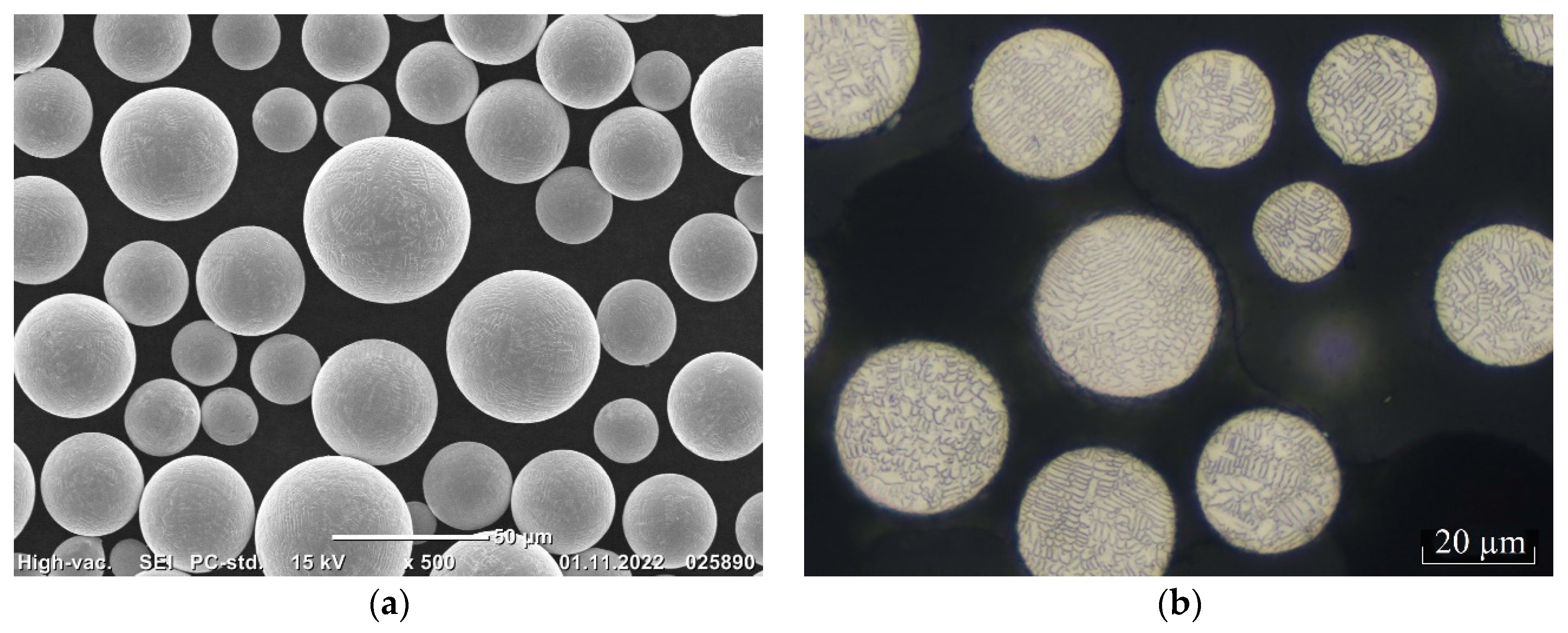
2.1. Starting Materials

Powder of the AZhK alloy for LPBF, which was fabricated by the plasma rotating electrode process, was used in this study. AZhK is a Ni-Cr-Mo-Co superalloy containing significant amounts of Al and Nb. The typical chemical composition of AzhK is shown in Table 1.
The particle size of the powder varied from 20 to 63 µm, with an average particle size of 45 µm; the d10, d50, and d90 quantiles of distribution were 23.0, 36.2, and 54.1 μm, respectively. Powder particles were spherical in shape, without satellites and gas pores (Figure 1a). The internal structure of the powders was represented by fine dendrites; no closed gas pores were detected (Figure 1). The bulk density measured according to ISO 3923–1:2008 was 4.61 g/cm3. The flowability of the powder determined in compliance with ASTM B213-17 was 14.4 s.

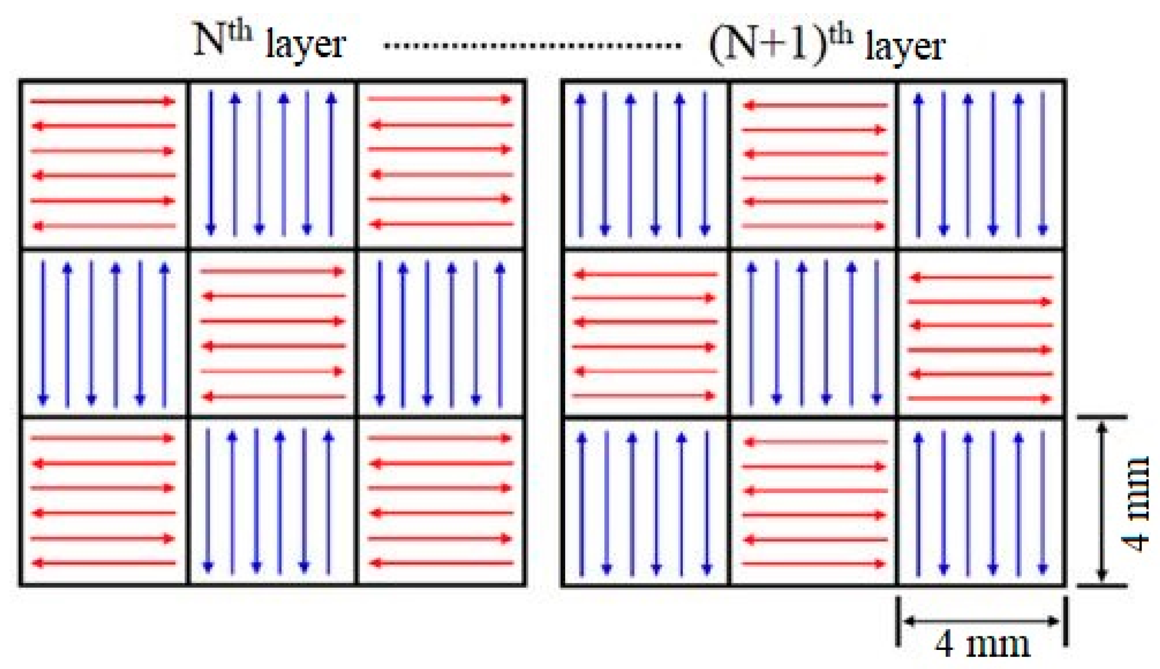
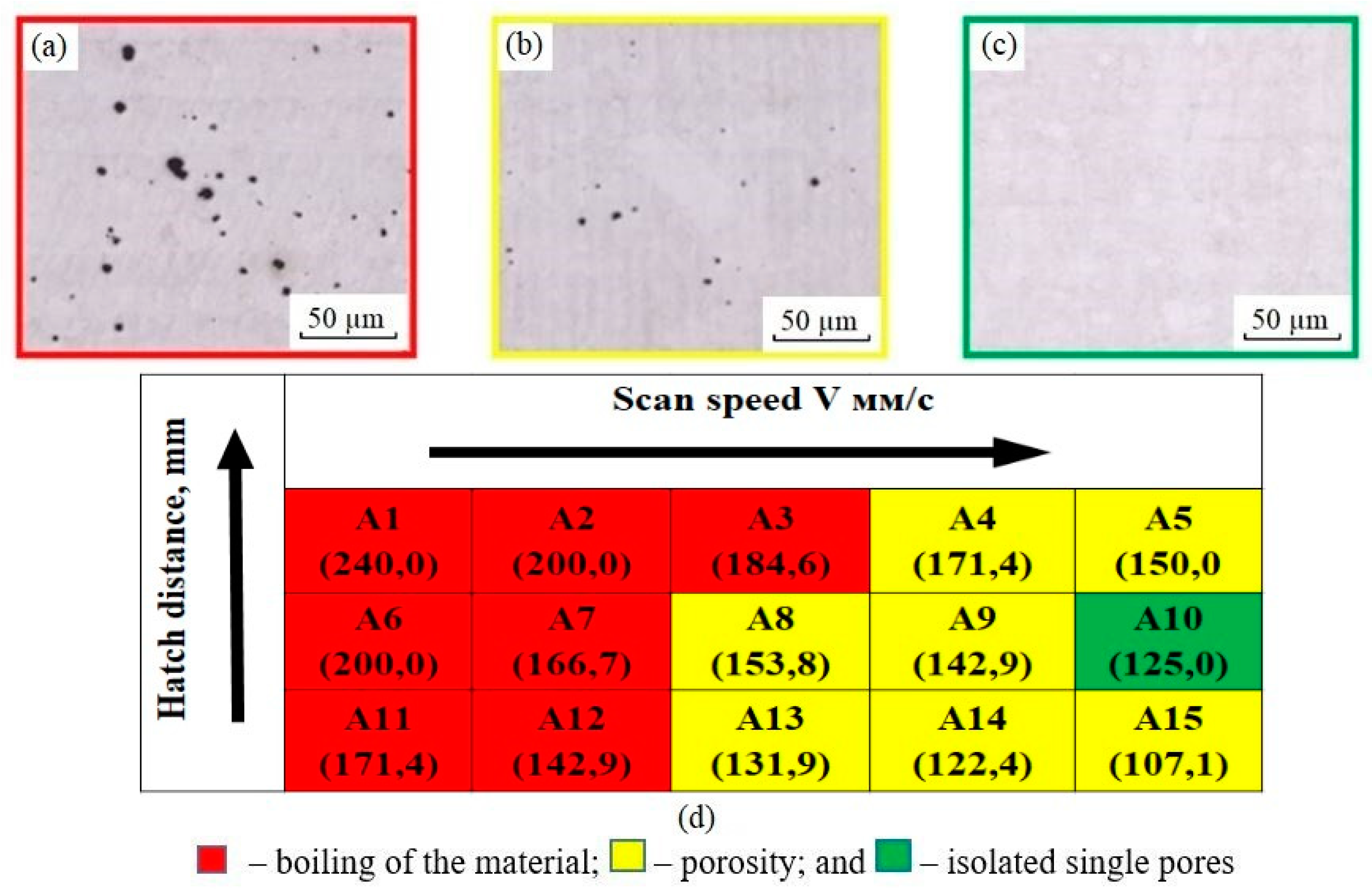
2.2. The LPBF Process

Laser powder bed fusion of AZhK powder was conducted in an argon atmosphere on a TruPrint 1000 machine (Trumpf, Ditzingen, Germany) equipped with a fiber laser with a rated power of 200 W and a build platform 100 mm in diameter. In the parametric studies, we varied the scan speed V from 500 to 800 mm/s and the hatch distance x from 0.05 to 0.07 mm, while power P, powder layer height h, and laser beam spot diameter d were kept constant (P = 120 W, h = 0.02 µm, and d = 0.03 mm). The working platform was not heated. The combined effect of the technological parameters of the LPBF process on the characteristics of the material was assessed using a volumetric energy density, VED [J/mm3]:
V E D = P V · h · x
where P is the laser power (W); V is the scan speed (mm/s); h is the powder layer height (mm); and x is the hatch distance (mm) [33,34,35].
Table 2 lists the analyzed laser powder bed fusion modes for building the samples and the respective VED values. The employed scanning strategy is schematically shown in Figure 2.
The optimal LPBF mode was selected according to the results of structural studies performed for the samples sized 10 mm × 10 mm × 10 mm (Figure 3a) and prepared during the parametric studies in the modes summarized in Table 2. Vertical cylindrical samples for mechanical tests (Figure 3b) and the ejector-type part (Figure 3c) were fabricated in the optimal mode (E—125.0 J/mm3). The cylindrical samples were 15 mm in diameter and 65 mm in height.

2.3. Post-Treatment

The samples produced by LPBF were subsequently subjected to various post-treatments: hot isostatic pressing (HIP), heat treatment (HT: solution + aging), and HIP + HT. HIP was carried out in an ABRA HIRP 10/26-200-2000 gasostat (ABRA AG, Winterthur, Switzerland) at 1160 °C and 150 MPa. Solution was performed at 1180 °C for 4 h. Aging was carried out at 820 °C for 16 h in a PL-10/16s thermal furnace (Russia). After quenching and aging, the samples were air-cooled.

2.4. Characterization

The structure and properties were studied for the following samples: LPBF samples; LPBF samples + HIP; LPBF samples + HT; LPBF samples + HIP + HT. The macrostructure and porosity of the samples were analyzed by optical microscopy (OM) using an AXIO Imager A1 reflection light microscope (CarlZeiss, Jena, Germany). The microstructure was investigated by scanning electron microscopy (SEM) on an S-3400N microscope (Hitachi High-Technologies Corporation, Tokyo, Japan). In order to detect the structural components, thin sections were etched using a solution of Marble’s reagent (copper sulfate, 20 g; hydrochloric acid, 100 mL; and water, 100 mL). High-resolution (HR) fine-structure study and phase identification were performed on a JEM-2100 transmission electron microscope (TEM) (Jeol, Tokyo, Japan). Foils for the HRTEM studies were prepared using a PHIPS II System dual-beam ion etching machine (Gatan, Inc., Pleasanton, CA, USA).
The hardness of the samples was measured on an HVS-50 Vickers hardness tester (Time Group Inc., Beijing, China) according to the State Standard GOST 2999 at a load of 10 kg. Tensile testing of the samples was carried out at room temperature in compliance with the State Standard GOST 1497 (ISO 6892), as well as at 650 and 750 °C in compliance with the State Standard GOST 9651 (ISO 783). The following characteristics were determined in the mechanical tests: ultimate tensile strength σ, yield point σ0.2, and relative elongation δ. A Schenk–Trebel RMC-100 testing machine (Schenk, Darmstadt, Germany) and an Ulvac sinku Rico furnace (ULVAC Technologies, Methuen, MA, USA) were used for the mechanical tests.
The geometric dimensions of the ejector-type part made of AZhK alloy were controlled using a Kreon ACE Arm-7 portable measuring arm (Kreon Technologies, Limoges, France). Control over internal defects in the ejector-type part was performed using a Phenix V|tome|x M300 X-ray microfocus CT system (Waygate Technologies, Wunstorf, Germany) equipped with two X-ray tubes for regulation and conducting linear measurements with an accuracy of 4 µm + L (mm)/100. The ejector-type part was scanned in the following mode: voltage, 270 kV; current, 178 µA; voxel size, 51 µm; and total scan time, 74 min.

3. Results and Discussion

3.1. The Structural Features of the LPBF Samples

An analysis of the test samples prepared in the parametric studies revealed the following structure types:
Structures with large circular pores, which have presumably resulted from boiling of the material (Figure 4a);
Structures with micropores distributed over the entire sample volume (Figure 4b);
Structures with isolated micropores (Figure 4c).
Figure 4d shows the experimental design matrix superimposed with the results of the structural studies. The top row of cells presents the notation of the modes (A1, A2, A3, etc.), while the bottom row of cells displays the porosity values calculated by analyzing the OM images. An analysis of the reported results confirms the hypothesis that the material boils at high energy inputs, resulting in the formation of large pores over the entire material volume. Porosity decreased as the energy input was reduced by increasing the scan speed. It is worth noting that the samples fabricated in the entire range of modes under study contained neither cracks nor incomplete fusion defects, thus proving the high manufacturability of the alloy during welding. The sample fabricated in mode E2 (E = 125.0 J/mm3) contained the fewest defects. This mode was chosen to be the optimal one for further studies of the structure and mechanical characteristics.
Figure 5a,b shows the macrostructure of the LPBF samples in the longitudinal and transverse cross-sections. In the cross-section parallel to the XY build plane, one can clearly see laser tracks (scan paths), while arcuate molten pool boundaries and columnar grains sized up to 200 µm were observed in the YZ build plane. The structure of the resulting samples was characterized by the minimal number of defects and residual porosity of <0.02%. The single pores were sized 1–5 µm. No structural defects such as cracks or incomplete fusion regions were detected.
Figure 5c,d shows the results of SEM structural studies. The presented SEM images demonstrate that the structure of the LPBF samples consisted of cellular and columnar primary dendrites. The columnar microstructure was formed at the molten pool boundary in the form of single primary dendrites, where they grew in the direction of heat dissipation during subsequent crystallization, which was accompanied by the formation of oriented colonies. Epitaxial growth of dendritic colonies through the molten pool boundary became possible as the next layer was welded on, resulting in the formation of columnar grains (Figure 5b). Suppression of the epitaxial mechanism was predominantly observed for this alloy due to the switching of the growth direction of columnar primary dendrites at the molten bath boundary by 90°, so that it had a cellular microstructure (Figure 5c).
Figure 6a shows a TEM image of the fine structure of the LPBF sample made of the AZhK alloy; Figure 6b presents an electron diffraction pattern for a dendritic cell oriented so that the [0–11] axis lay parallel to the optical axis of the microscope and corresponded to the Ni-based matrix (the austenite γ-phase) with the calculated fcc lattice parameter of 3.5174 Å (the tabular value was 3.5238 Å). The structure of the synthesized material was characterized by high density of dislocations predominantly aggregated along the boundaries of the dendritic cells of the γ-phase. The cell size varied from 0.5 to 1.0 µm. Dislocation aggregates were indicative of high internal stress in the alloy after LPBF. Therefore, relaxation annealing was needed before the parts were cut off from the build plate when building geometrically complex and thin-walled items, as it prevented geometry distortion caused by their deformation.
To assess the segregation of heavy alloying elements, local EDX analysis was carried out at points corresponding to the matrix (spectra 2, 3, 8, 14), the boundaries of dendritic grains (spectra 4, 5, 6, 12), and the precipitated particles (spectra 1, 7, 9, 10, 11, 13) presented in Figure 7a,b. The results of the local EDX are presented in Table 3.
The presented results indicate that the boundaries of the dendritic cells are mainly enriched in niobium, while the particles in the interdendritic space are enriched in elements such as molybdenum, niobium, and hafnium, and in one case, a particle with carbon and increased aluminum content is observed (spectrum 7).
The phases detected in the interdendritic space were identified by HRTEM. Figure 8 shows images of the particles detected in the interdendritic space and the respective Fourier transform (FFT) images. An analysis of FFT revealed that there were two carbides (Nb6C4.87 and Nb4AlC3) and the Laves phase (Mo2Hf). Table 4 summarizes the results of the calculations. These phases were brittle and unstable; they were undesirable because they deteriorated mechanical properties of the material [36,37,38,39,40,41]. In order to get rid of these phases, we suggest conducting post-treatment procedures (HIP and HT) [22,23,38,42].

3.2. The Structural Features of the LPBF Samples after HIP

HIP of the LPBF samples fabricated from the AZhK alloy ensured the formation of a granular microstructure without any characteristic features such as laser tracks or molten pool boundaries (Figure 9a). Furthermore, the volumetric porosity of the LPBF samples decreased to 0.013%.
Figure 9b shows SEM images of the microstructure of the LPBF samples after HIP. The microstructure consisted of the γ-phase strengthened with Ni3Al-based intermetallic inclusions (the γ′-phase). The grain boundary was formed of the chains of elongated γ′-phase particles sized up to 3 µm. The γ′-phase was distributed over the bulk of a grain as cubic inclusions up to 1 µm in size, which formed agglomerates consisting of 2–4 particles each (octocubes). According to their morphology, the agglomerates could be classified as the transitional shape between octocubes and octodendrites. The morphology of the γ′-phase is known to predominantly depend on dopants in the alloy and the cooling rate [43]. In this case, the shape and the larger size of γ′-phase grains were related to the low cooling rate after HIP. A TEM image is shown in Figure 9c. After HIP, aggregation of dislocations was no longer observed in the bulk of the sample, which is indicative of internal stress relaxation in the alloy. Nanoparticles with a faceted and spherical shape were detected inside the matrix grains (Figure 10). To determine the composition of the particles, a local EDX analysis was conducted, and the results are presented in Table 5. From the presented results, it can be noted that, in particle 1 (Figure 10a), there is an increased content of Cr, Co, and Mo, and in particle 2 (Figure 10b), there is an increased content of Hf and Al. The obtained results suggest that carbide compounds are formed during the HIP process, which include several elements. An analysis of the FFT images obtained by processing high-resolution images allowed us to infer that they belonged to MeC-type carbides (Ni,Mo)C and (Hf,Al)C.
The lattice parameters of the (Ni,Mo)C carbide were determined by analyzing the FFT image according to interplanar distances between the (0110), (1010), and (1100) planes: a = 11.0262 Å (the tabular lattice parameter was 10.8932 Å). The lattice parameters of the (Hf,Al)C particle with an hcp structure were a = 3.21 Å and c = 28.45 Å (the tabular values were a = 3.32 Å and a = 27.42 Å) (Figure 10c). The lattice parameters of carbides deviated from the tabular values because of the dissolution of nickel or aluminum in them.

3.3. The Structural Features of the LPBF Samples after HIP and HT

After HT, the grain structure was characterized by more well-defined grain boundaries (Figure 11a). The grains were equiaxed; their size in the direction of the Z axis was ≤250 µm. Figure 11b shows the microstructure after HT. One can see that HT contributed to the comminution of the γ′-phase with a cubic morphology. Carbide phases, presumably M23C6-type ones, typical of heat-resistant nickel alloys, were formed at the grain boundaries.
To determine the composition of the precipitated phases at the grain boundary, a local EDX analysis was conducted at points corresponding to the γ/γ′-phases (spectra 6, 8, 10) and directly to the grain boundary itself (spectra 1–5, 7, 9), as shown in Figure 12. The results of the local EMF are summarized in Table 6. The spectra corresponding to the γ/γ′-phases show an increased content of Ni, Cr, Co, and Al, which is typical for these phases. The remaining spectra showed high content of Mo, Cr, or Ni in the particles found at the boundaries and inside the grains. The composition of these particles indicates the formation of carbides of the M23C6 type (Figure 12, Table 6).
Figure 13a shows a TEM image of the grain boundary in the LPBF sample fabricated from the AZhK alloy after HIP and HT. The grain size of the γ′-phase varied within the range from 100 to 250 nm. Figure 11b displays particles that have precipitated along the grain boundaries, which were identified by performing the Fourier transform of the respective zones in the HR-TEM images with the atomic-resolution crystal structure. An analysis of the FFT images (Figure 13d,e) revealed that they belonged to the Cr23C6-type carbide. The calculated lattice parameter for the particle shown in Figure 13b,c was a = 10.92 Å and a = 10.84 Å, respectively, while the tabular value was a = 10.65 Å. The slightly increased (approximately by 2%) unit cell of carbide can be attributed to the dissolution of molybdenum in it.

3.4. Hardness of LPBF Samples after HIP and HT

Table 7 lists the average hardness values for the as-built LPBF samples fabricated from the AZhK alloy and those exposed to HIP and HT in the XY and YZ planes with respect to the build platform. The presented data indicate that hardness of the samples varied negligibly depending on the plane. Hardness in the as-built LPBF samples was low because the nickel matrix contained no strengthening phases. After the HIP procedure, hardness increased by 35 HV units due to precipitation of the γ′ phase. The maximum hardness (445 HV) was attained after HT because of uniform segregation of the coherent fine-grained γ′-phase from the nickel matrix. We would like to mention that the AZhK alloy after HT was characterized by high hardness compared to that of other known superalloys, such as Inconel 718 and Inconel 625 [38,44,45,46].

3.5. Tensile Strength of the LPBF Samples after HIP and HT

The results of room temperature tensile testing of the LPBF samples after various combinations of treatments are summarized in the stress–strain diagram (Figure 14) and in Table 8.
The relatively low strength and high ductility of this alloy are caused by the fact that the LPBF samples fabricated from the AZhK alloy contained neither strengthening γ′-phase precipitates nor high-melting dopants that would strengthen the γ-phase. It follows from the reported data that post-treatment substantially enhanced the strength of the LPBF samples from 30% (after HIP) to 45% (after HT), while their ductility remained fairly good. Improvement of properties was primarily related to the segregation of the γ′-phase from the supersaturated γ-matrix. The morphology, size, and homogeneous distribution of the coherent γ′-phase in the matrix phase, which ensured the maximum strength of the LPBF samples, played a crucial role in the case of HT. Since the elaborated LPBF mode for the AZhK alloy gave rise to a structure with the fewest defects, the properties of the LPBF + HT and LPBF + HIP + HT samples were very close. The properties of the samples fabricated from the AZhK alloy using the conventional powder metallurgy technology (P/M by HIP) are listed in Table 8 for comparison. The reported data indicate that the required level of mechanical properties of the synthesized AZhK alloy was attained after post-treatment in the HIP + HT or HT modes. Therefore, HT as the manufacturing process was mandatory for fabricating critical parts from the AZhK alloy synthesized by LPBF.
The stress–strain curves and mechanical properties during tensile tests of the synthesized material of AZhK grade at test temperatures of 650 and 750 °C are shown in Figure 15 and Table 9. The tests were performed for the as-built LPBF samples and after HIP + HT.
The ultimate tensile strength and the offset yield point of the LPBF samples are significantly inferior to the nominal values, thus limiting the use of the as-built material. As already mentioned above, the low mechanical properties of the LPBF samples are related to the absence of coherent precipitates of the strengthening γ′-phase and complex carbides in the structure of the material. For the desired level of service properties to be attained, the combined post-treatment in the HIP + HT mode needs to be performed.
Therefore, the structure evolution improved properties of the LPBF samples at 650 °C by: σ, 332 MPa (37%); σ0.2, 220 MPa (32%); σ, 367 MPa (51%); and σ0.2, 357 MPa (64%) at 750 °C, respectively. Note that the mechanical properties of the LPBF samples fabricated from the AZhK alloy after HIP + HT were better than those for the samples obtained using the P/M by HIP technology.

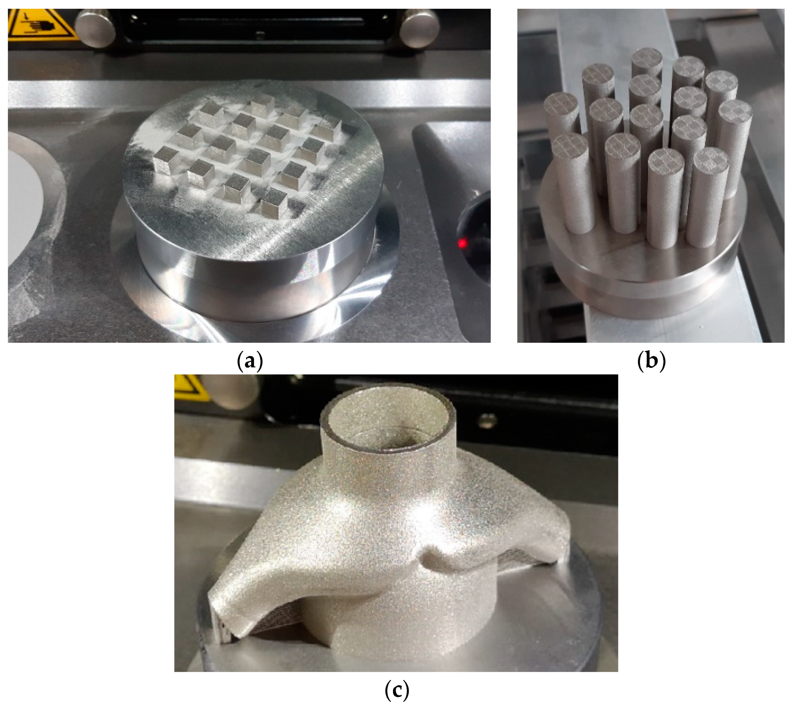
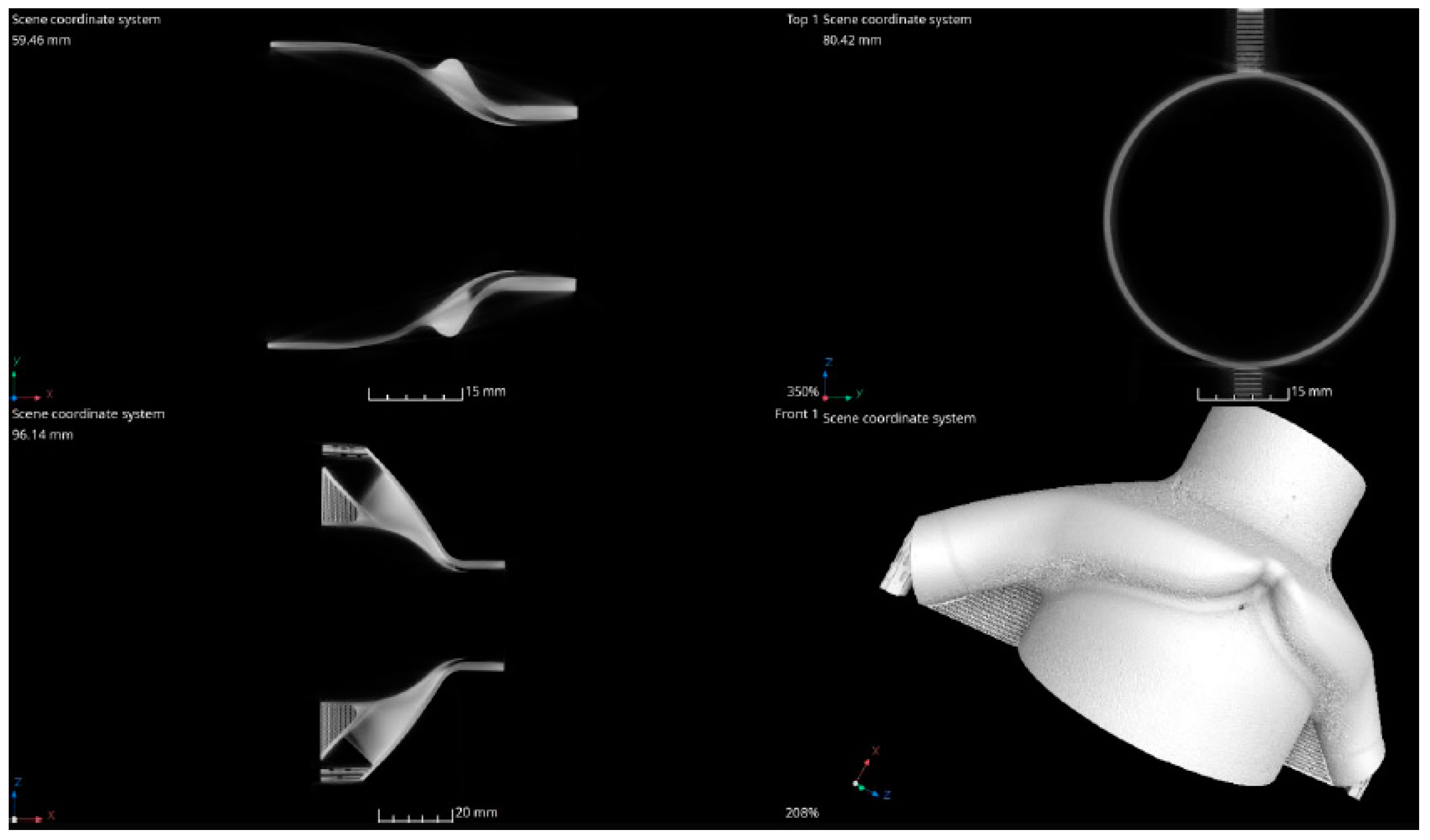
3.6. Fabrication of the Ejector-Type Detail from the AZhK Alloy

In accordance with the developed LPBF modes, an ejector-type part was fabricated for the high-melting nickel melt AZhK; its appearance is shown in Figure 3c. The product was intended for reducing the temperature of the working gas from 850 to 450 °C. During the operation, the working gas heated to 850 °C was fed through the central channel; to reduce its temperature, a similar gas with a temperature of 200 °C was fed through two lateral channels. As a result, both gases were ejected, thus reducing the gas temperature in the central region to 450 °C. Due to this process, the temperature of the energy source material decreased, while its speed characteristics remained unchanged, which is an important aspect of engine operation.
The map of deviations of the geometric size of the ejector-type detail fabricated from the AZhK alloy after LPBF (tolerance of ±0.1 mm with respect to the initial electron model) is shown in Figure 16. The findings demonstrate that the deviation between the geometric parameters of the part and the specified values lay above the permissible limit (shown in blue color). These deviations are not critical and do not disrupt the functionality of the part. According to these findings, we have made deviation adjustments to the original electron model.
The computed tomography data (Figure 17) have shown that the LPBF mode used for the AZhK alloy ensures the absence of structure discontinuities in the form of incomplete fusion defects, microcracks, and pores sized ≥20 µm, as well as compliance between the geometric parameters of the inner channels for mixing the gas in the electronic model. Channels of the fabricated part after LPBF contained no sintered powder, thus making it unnecessary to perform additional processes for their vibrational cleaning using additional equipment.

4. Conclusions

Our conclusions are as follows:
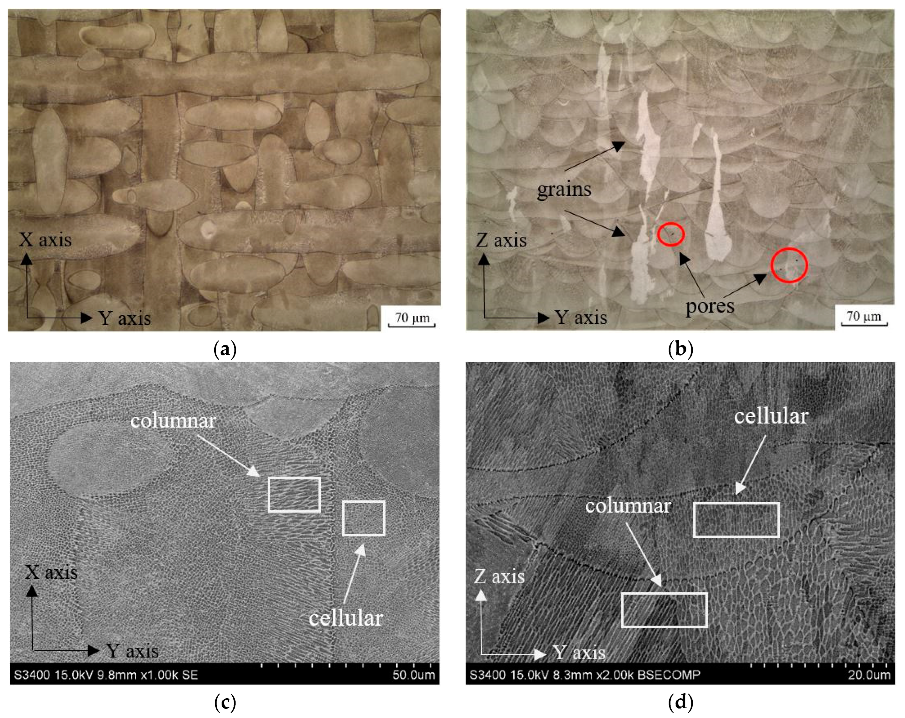
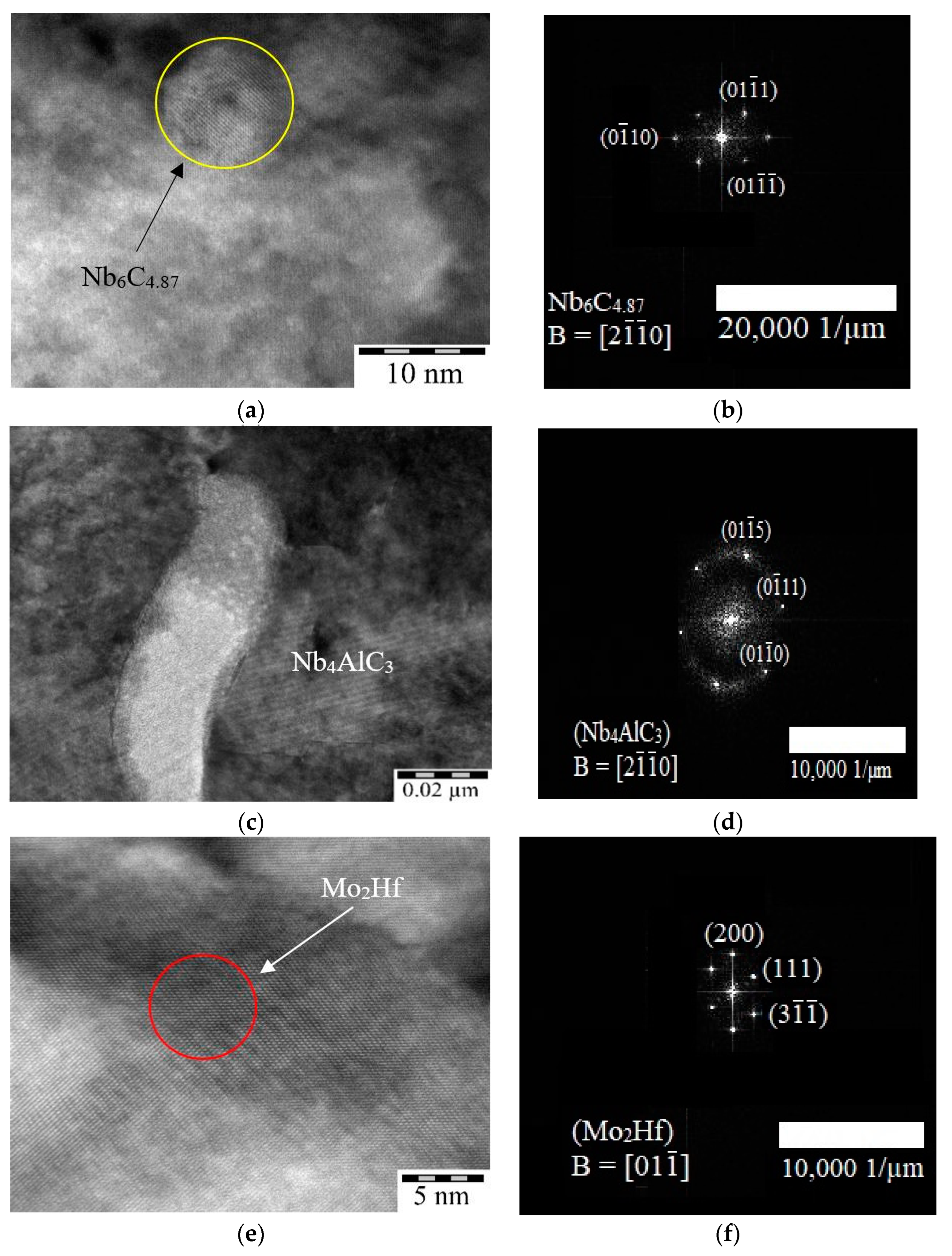
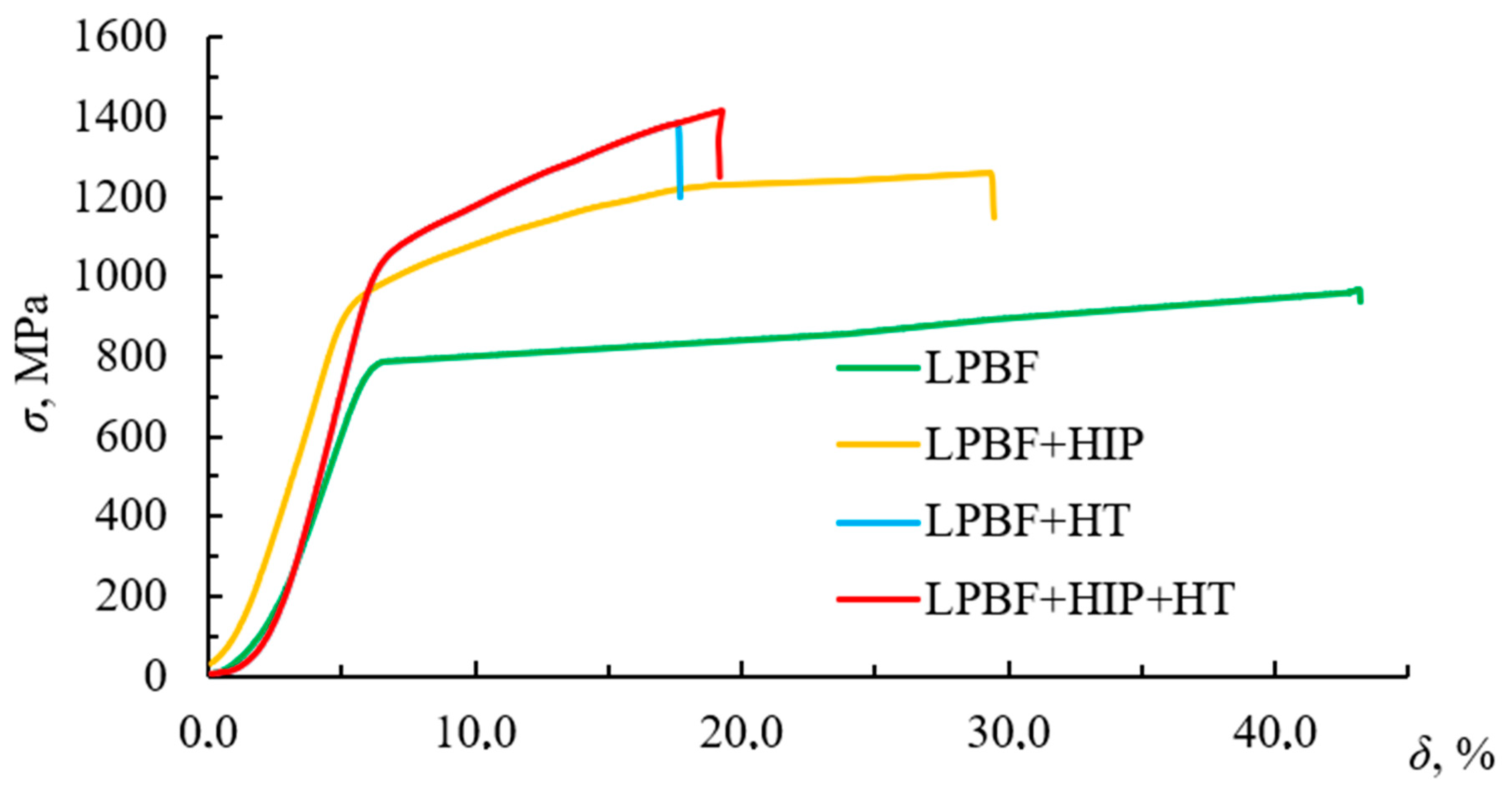
  • The optimal E2 mode of LPBF for the AZhK alloy (E = 125.0 J/mm3) has been identified, ensuring attainment of a residual porosity of 0.02%. The macrostructure of the LPBF samples consisted of columnar grains oriented in the direction of predominant heat dissipation, perpendicular to the build plane. At the microlevel, the structure was represented by colonies of columnar dendrites. The Nb4AlC3 and Nb6C4 carbide phases as well as the Mo2Hf Laves phase were precipitated in the interdendritic region as a result of dopant segregation. The low strength of the LPBF samples manufactured from the AZhK alloy (σ = 967 ± 10 MPa) was related to the absence of strengthening γ′-phase particles and stable carbides.
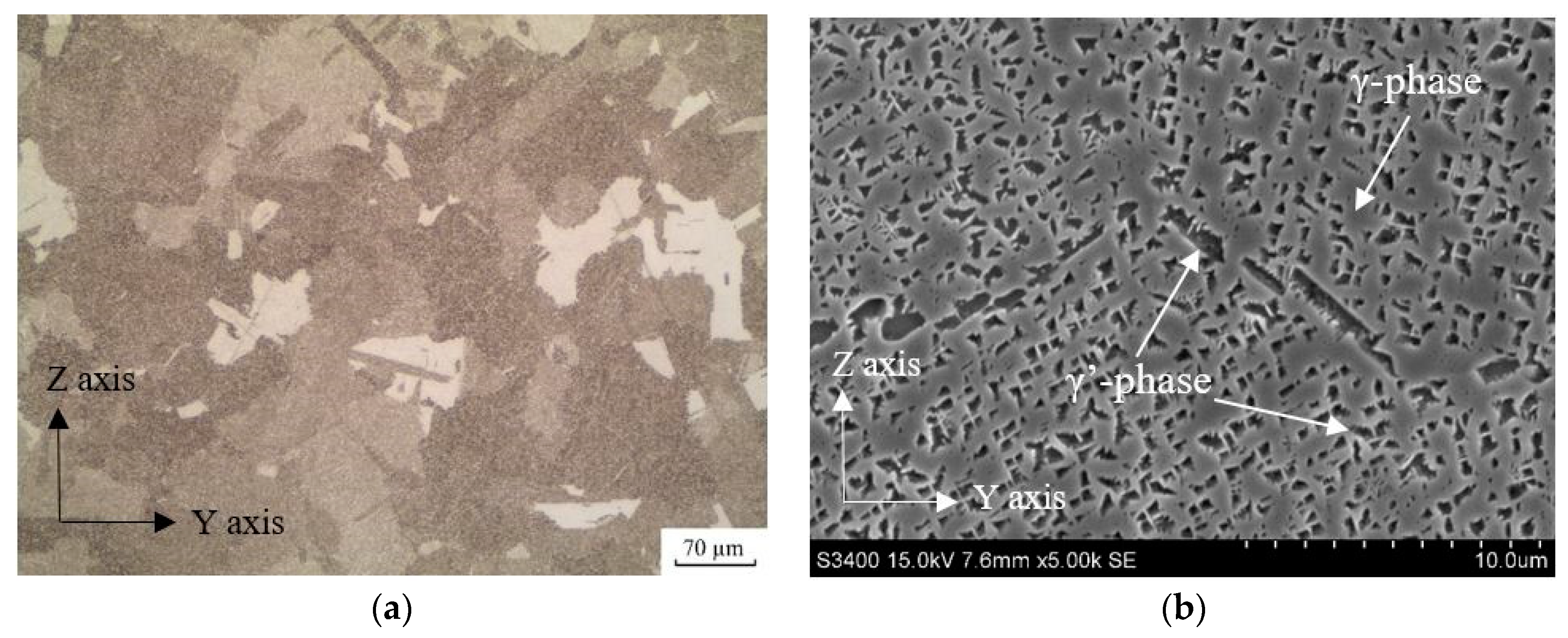
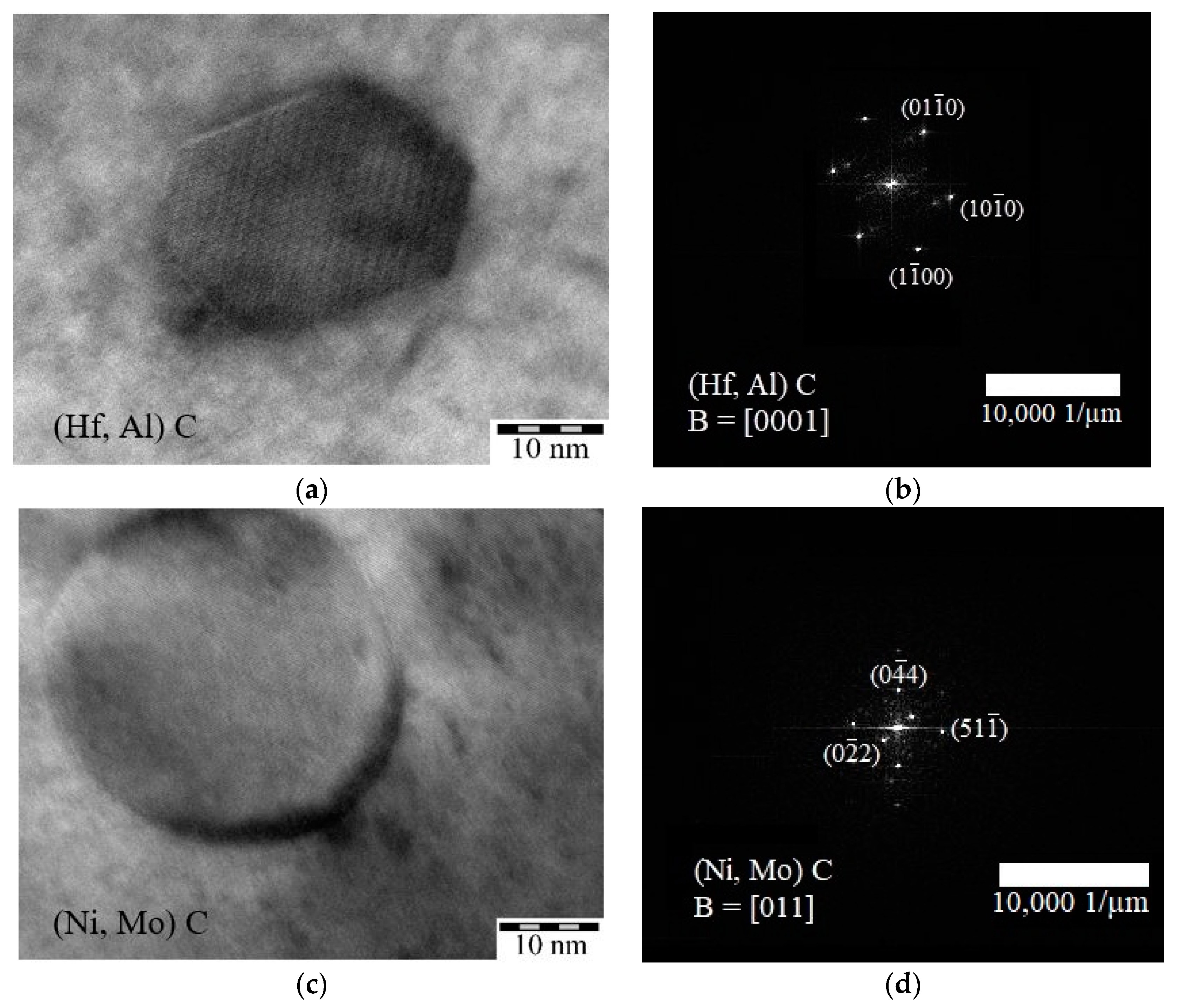
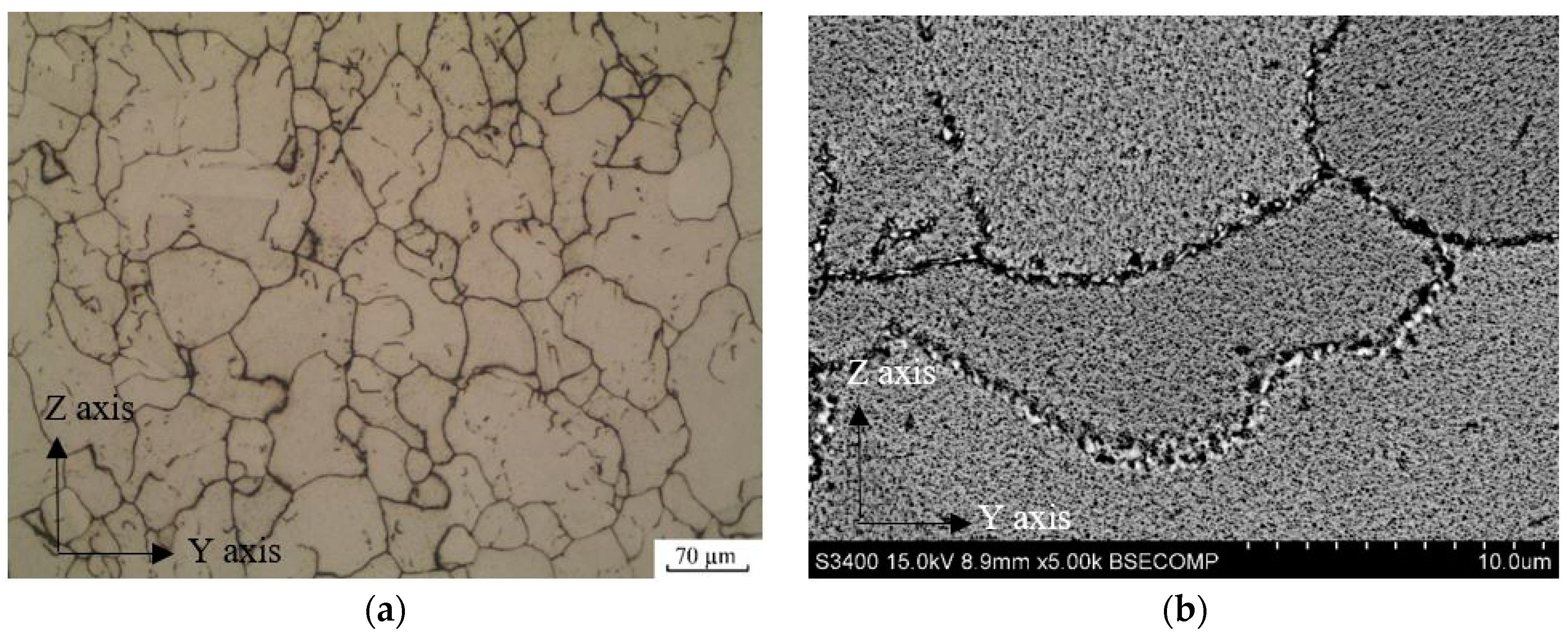
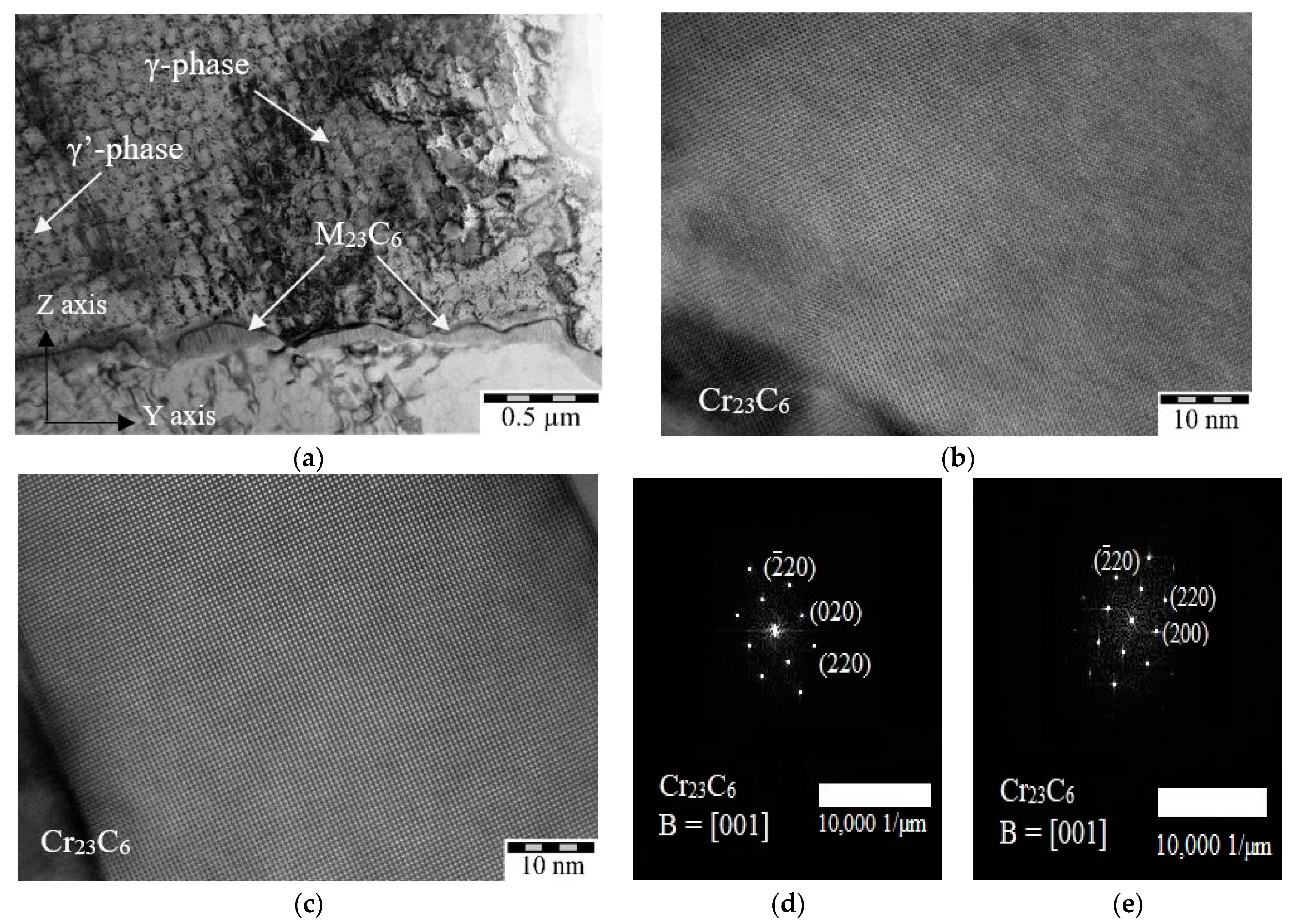
  • The γ′-phase particles sized up to 2 µm and MC-type Mo- and Hf-based carbides were precipitated during HIP. No Laves phases were detected in the structure of LPBF samples after HIP, as they were dissolved as a result of diffusion. Heat treatment ensured the homogeneous segregation of the fine-grained γ′-phase with a cubic morphology (sized up to 250 nm) and additional precipitation of Cr23C6-type carbides at grain boundaries.
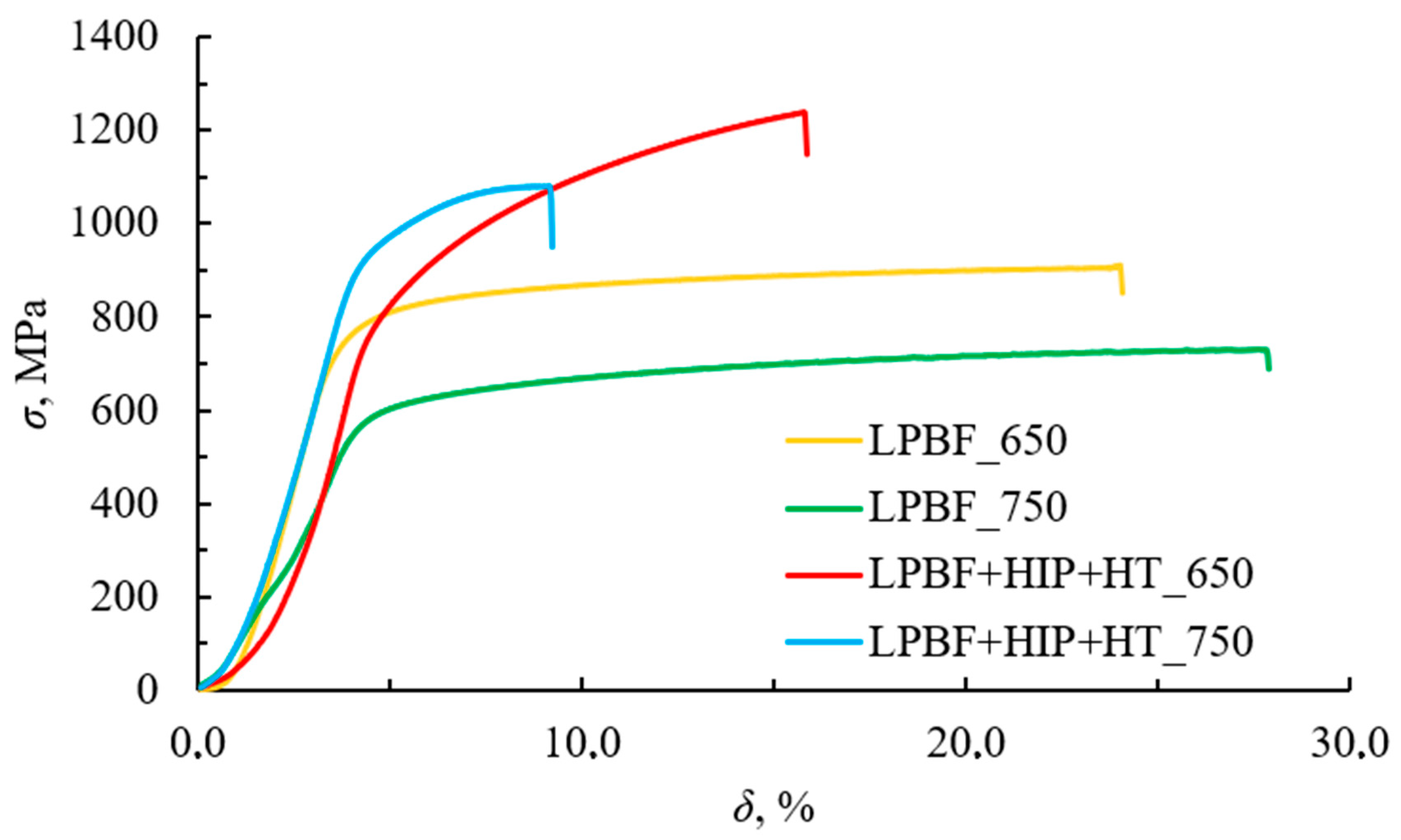
  • The strength and ductility of the LPBF samples fabricated from the AZhK alloy were increased due to solid-solution precipitation of the fine-grained γ′-phase and MC-type carbide phases inside the matrix phase grains and M23C6 at grain boundaries. The following maximum values were obtained: at 20 °C, σ20 = 1396 ± 22 MPa and δ = 19.0 ± 3.0 %; at 650 °C, σ650 = 1240 ± 25 MPa and δ = 15.8 ± 1.5%; and at 750 °C, σ750 = 1085 ± 23 MPa and δ = 9.1 ± 2.3%.
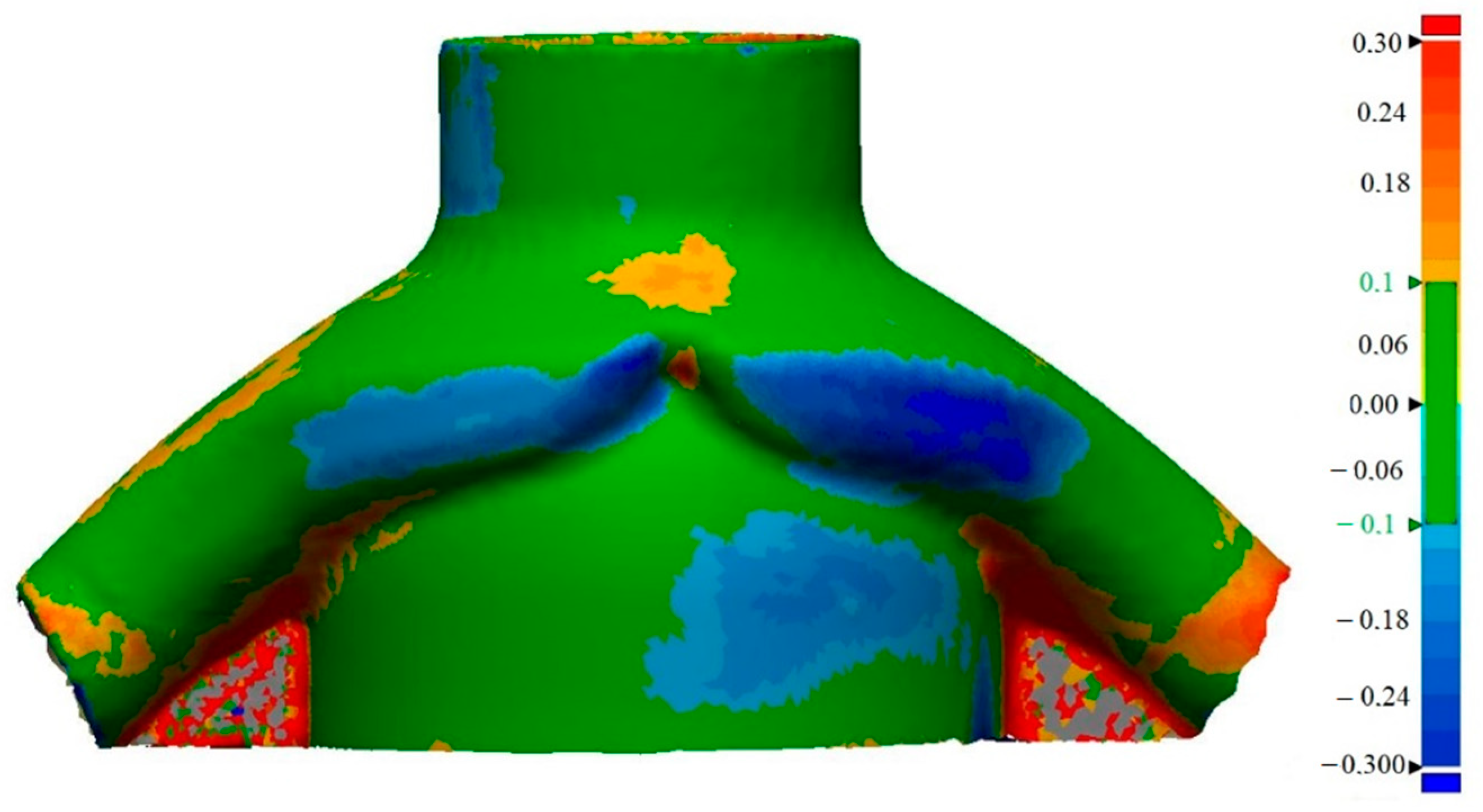
  • A geometrically complex ejector-type part was manufactured using the developed LPBF technology; its geometric parameters corresponded to those of the electronic models, while the base material was free of defects (microcracks or pores) sized more than 20 µm.

Author Contributions

Conceptualization, Z.A.S.; Methodology, F.A.B. and Z.A.S.; Software, E.A.L.; Validation, F.A.B. and Z.A.S.; Formal analysis, Z.A.S.; Investigation, F.A.B., P.A.L., M.Y.B. and I.A.L.; Writing—original draft, F.A.B. and I.A.L.; Supervision, E.A.L. All authors have read and agreed to the published version of the manuscript.

Funding

This work was supported by the Russian Science Foundation (project No. 19-79-10226).

Conflicts of Interest

The authors declare no conflict of interest.

References

  1. Armstrong, M.; Mehrabi, H.; Naveed, N. An overview of modern metal additive manufacturing technology. J. Manuf. Process. 2022, 84, 1001–1029. [Google Scholar] [CrossRef]
  2. Vafadar, A.; Guzzomi, F.; Rassau, A.; Hayward, K. Advances in Metal Additive Manufacturing: A Review of Common Processes, Industrial Applications, and Current Challenges. Appl. Sci. 2021, 11, 1213. [Google Scholar] [CrossRef]
  3. Cooke, S.; Ahmadi, K.; Willerth, S.; Herring, R. Metal additive manufacturing: Technology, metallurgy and modelling. J. Manuf. Process. 2020, 57, 978–1003. [Google Scholar] [CrossRef]
  4. Aboulkhair, N.T.; Bosio, F.; Gilani, N.; Phutela, C.; Hague, R.J.; Tuck, C.J. Additive manufacturing processes for metals. In Quality Analysis of Additively Manufactured Metals; Elsevier: Amsterdam, The Netherlands, 2023; pp. 201–258. [Google Scholar] [CrossRef]
  5. Katz-Demyanetz, A.; Popov, V.V.; Kovalevsky, A.; Safranchik, D.; Koptyug, A. Powder-bed additive manufacturing for aerospace application: Techniques, metallic and metal/ceramic composite materials and trends. Manuf. Rev. 2019, 6, 5. [Google Scholar] [CrossRef] [Green Version]
  6. Salunkhe, S.; Rajamani, D. Current trends of metal additive manufacturing in the defense, automobile, and aerospace industries. In Woodhead Publishing Reviews: Mechanical Engineering Series—Advances in Metal Additive Manufacturing; Woodhead Publishing: Sawston, UK, 2023; pp. 147–160. [Google Scholar] [CrossRef]
  7. Altıparmak, S.C.; Xiao, B. A market assessment of additive manufacturing potential for the aerospace industry. J. Manuf. Process. 2021, 68 Pt A, 728–738. [Google Scholar] [CrossRef]
  8. Blakey-Milner, B.; Gradl, P.; Snedden, G.; Brooks, M.; Pitot, J.; Lopez, E.; Leary, M.; Berto, F.; du Plessis, A. Metal additive manufacturing in aerospace: A review. Mater. Des. 2021, 209, 110008. [Google Scholar] [CrossRef]
  9. Boyer, R.; Cotton, J.; Mohaghegh, M.; Schafrik, R. Materials considerations for aerospace applications. MRS Bull. 2015, 40, 1055–1066. [Google Scholar] [CrossRef] [Green Version]
  10. Bhat, B.N. (Ed.) Aerospace Materials and Applications; American Institute of Aeronautics and Astronautics, Inc.: Reston, VA, USA, 2018. [Google Scholar] [CrossRef]
  11. Akhtar, W.; Sun, J.; Sun, P.; Chen, W.; Saleem, Z. Tool wear mechanisms in the machining of Nickel based super-alloys: A review. Front. Mech. Eng. 2014, 9, 106–119. [Google Scholar] [CrossRef]
  12. Ezugwu, E.; Bonney, J.; Yamane, Y. An overview of the machinability of aeroengine alloys. J. Mater. Process. Technol. 2003, 134, 233–253. [Google Scholar] [CrossRef]
  13. Frazier, W.E. Metal Additive Manufacturing: A Review. J. Mater. Eng. Perform. 2014, 23, 1917–1928. [Google Scholar] [CrossRef]
  14. Froes, F.; Boyer, R. Additive Manufacturing for the Aerospace Industry; Elsevier: Amsterdam, The Netherlands, 2019; 482p. [Google Scholar]
  15. Hosseini, E.; Popovich, V. A review of mechanical properties of additively manufactured Inconel 718. Addit. Manuf. 2019, 30, 100877. [Google Scholar] [CrossRef]
  16. Sanchez, S.; Smith, P.; Xu, Z.; Gaspard, G.; Hyde, C.J.; Wits, W.W.; Ashcroft, I.A.; Chen, H.; Clare, A.T. Powder Bed Fusion of nickel-based superalloys: A review. Int. J. Mach. Tools Manuf. 2021, 165, 103729. [Google Scholar] [CrossRef]
  17. Volpato, G.M.; Tetzlaff, U.; Fredel, M.C. A comprehensive literature review on laser powder bed fusion of Inconel superalloys. Addit. Manuf. 2022, 55, 102871. [Google Scholar] [CrossRef]
  18. Han, Q.; Gu, Y.; Setchi, R.; Lacan, F.; Johnston, R.; Evans, S.L.; Yang, S. Additive manufacturing of high-strength crack-free Ni-based Hastelloy X superalloy. Addit. Manuf. 2019, 30, 100919. [Google Scholar] [CrossRef]
  19. Han, Q.; Mertens, R.; Montero-Sistiaga, M.L.; Yang, S.; Setchi, R.; Vanmeensel, K.; Van Hooreweder, B.; Evans, S.L.; Fan, H. Laser powder bed fusion of Hastelloy X: Effects of hot isostatic pressing and the hot cracking mechanism. Mater. Sci. Eng. A 2018, 732, 228–239. [Google Scholar] [CrossRef]
  20. Boswell, J.H.; Clark, D.; Li, W.; Attallah, M.M. Cracking during thermal post-processing of laser powder bed fabricated CM247LC Ni-superalloy. Mater. Des. 2019, 174, 107793. [Google Scholar] [CrossRef]
  21. Wang, X.; Carter, L.N.; Pang, B.; Attallah, M.M.; Loretto, M.H. Microstructure and yield strength of SLM-fabricated CM247LC Ni-Superalloy. Acta Mater. 2017, 128, 87–95. [Google Scholar] [CrossRef]
  22. Sentyurina, Z.; Baskov, F.; Loginov, P.; Kaplanskii, Y.; Mishukov, A.; Logachev, I.; Bychkova, M.; Levashov, E.; Logacheva, A. The effect of hot isostatic pressing and heat treatment on the microstructure and properties of EP741NP nickel alloy manufactured by laser powder bed fusion. Addit. Manuf. 2020, 37, 101629. [Google Scholar] [CrossRef]
  23. Baskov, F.; Sentyurina, Z.; Kaplanskii, Y.; Logachev, I.; Semerich, A.; Levashov, E. The influence of post heat treatments on the evolution of microstructure and mechanical properties of EP741NP nickel alloy produced by laser powder bed fusion. Mater. Sci. Eng. A 2021, 817, 141340. [Google Scholar] [CrossRef]
  24. Raisson, G.; Guédou, J.Y.; Guichard, D.; Rongvaux, J.M. Production of Net-Shape Static Parts by Direct HIPing of Nickel Base Superalloy Prealloyed Powders. Adv. Mater. Res. 2011, 278, 277–282. [Google Scholar] [CrossRef] [Green Version]
  25. Samarov, V.; Barre, C.; Khomyakov, E.; Haykin, R. Net Shape HIP for Complex Shape PM Parts as A Cost-Efficient Industrial Technology. In Proceedings of the 8th International Conference on Hot Isostatic Pressing, Paris, France; 2005; pp. 48–52. [Google Scholar]
  26. Baccino, R.; Moret, F.; Pellerin, F.; Guichard, D.; Raisson, G. High performance and high complexity net shape parts for gas turbines: The ISOPREC® powder metallurgy process. Mater. Des. 2000, 21, 345–350. [Google Scholar] [CrossRef]
  27. Bassini, E.; Vola, V.; Lorusso, M.; Ghisleni, R.; Lombardi, M.; Biamino, S.; Ugues, D.; Vallillo, G.; Picqué, B. Net shape HIPping of Ni-superalloy: Study of the interface between the capsule and the alloy. Mater. Sci. Eng. A 2017, 695, 55–65. [Google Scholar] [CrossRef]
  28. Lacroix, R.; Seifert, R.W.; Timonina-Farkas, A. Benefiting from additive manufacturing for mass customization across the product life cycle. Oper. Res. Perspect. 2021, 8, 100201. [Google Scholar] [CrossRef]
  29. Attaran, M. The rise of 3-D printing: The advantages of additive manufacturing over traditional manufacturing. Bus. Horiz. 2017, 60, 677–688. [Google Scholar] [CrossRef]
  30. Westerweel, B.; Basten, R.J.; van Houtum, G.-J. Traditional or Additive Manufacturing? Assessing Component Design Options through Lifecycle Cost Analysis. Eur. J. Oper. Res. 2018, 270, 570–585. [Google Scholar] [CrossRef] [Green Version]
  31. Kamal, M.; Rizza, G. Design for metal additive manufacturing for aerospace applications. In Additive Manufacturing for the Aerospace Industry; Elsevier: Amsterdam, The Netherlands, 2019; pp. 67–86. [Google Scholar] [CrossRef]
  32. Barz, A.; Buer, T.; Haasis, H.-D. A Study on the Effects of Additive Manufacturing on the Structure of Supply Networks. IFAC-PapersOnLine 2016, 49, 72–77. [Google Scholar] [CrossRef]
  33. Stegman, B.; Shang, A.; Hoppenrath, L.; Raj, A.; Abdel-Khalik, H.; Sutherland, J.; Schick, D.; Morgan, V.; Jackson, K.; Zhang, X. Volumetric energy density impact on mechanical properties of additively manufactured 718 Ni alloy. Mater. Sci. Eng. A 2022, 854, 143699. [Google Scholar] [CrossRef]
  34. Caiazzo, F.; Alfieri, V.; Casalino, G. On the Relevance of Volumetric Energy Density in the Investigation of Inconel 718 Laser Powder Bed Fusion. Materials 2020, 13, 538. [Google Scholar] [CrossRef] [Green Version]
  35. Watring, D.S.; Benzing, J.T.; Hrabe, N.; Spear, A.D. Effects of laser-energy density and build orientation on the structure–property relationships in as-built Inconel 718 manufactured by laser powder bed fusion. Addit. Manuf. 2020, 36, 101425. [Google Scholar] [CrossRef]
  36. Chlebus, E.; Gruber, K.; Kuźnicka, B.; Kurzac, J.; Kurzynowski, T. Effect of heat treatment on the microstructure and mechanical properties of Inconel 718 processed by selective laser melting. Mater. Sci. Eng. A 2015, 639, 647–655. [Google Scholar] [CrossRef]
  37. Sui, S.; Li, Z.; Zhong, C.; Zhang, Q.; Gasser, A.; Chen, J.; Chew, Y.; Bi, G. Laves phase tuning for enhancing high temperature mechanical property improvement in laser directed energy deposited Inconel 718. Compos. Part B Eng. 2021, 215, 108819. [Google Scholar] [CrossRef]
  38. Tucho, W.M.; Cuvillier, P.; Sjolyst-Kverneland, A.; Hansen, V. Microstructure and hardness studies of Inconel 718 manufactured by selective laser melting before and after solution heat treatment. Mater. Sci. Eng. A 2017, 689, 220–232. [Google Scholar] [CrossRef]
  39. Parimi, L.L.; Ravi, G.; Clark, D.; Attallah, M.M. Microstructural and texture development in direct laser fabricated IN718. Mater. Charact. 2014, 89, 102–111. [Google Scholar] [CrossRef]
  40. Bhavsar, R.B.; Collins, A.; Silverman, S. Use of alloy 718 and 725 in oil and gas industry. In Superalloys 718, 625, 706 and various derivatives; Lorin, E.A., Ed.; TMS (The Alinernls. Metals: Materials Society): Pittsburgh, PA, USA, 2001; pp. 47–55. [Google Scholar]
  41. Janaki Ram, G.D.; Venugopal Reddy, A.; Prasad Rao, K.; Reddy, G.M. Microstructure and mechanical properties of Inconel 718 electron beam welds. Mater. Sci. Technol. 2005, 10, 1132–1138. [Google Scholar]
  42. Li, X.; Shi, J.; Wang, C.; Cao, G.; Russell, A.; Zhou, Z.; Li, C.; Chen, G. Effect of heat treatment on microstructure evolution of Inconel 718 alloy fabricated by selective laser melting. J. Alloys Compd. 2018, 764, 639–649. [Google Scholar] [CrossRef]
  43. Grosdidier, T.; Hazotte, A.; Simon, A. Precipitation and dissolution processes in γ/γ′ single crystal nickel-based superalloys. Mater. Sci. Eng. A 1998, 256, 183–196. [Google Scholar] [CrossRef]
  44. Popovich, V.; Borisov, E.; Sufiiarov, V.; Masaylo, D.; Alzina, L. Impact of heat treatment on mechanical behaviour of Inconel 718 processed with tailored microstructure by selective laser melting. Mater. Des. 2017, 131, 12–22. [Google Scholar] [CrossRef]
  45. Feng, K.-Y.; Liu, P.; Li, H.-X.; Sun, S.-Y.; Xu, S.-B.; Li, J.-N. Microstructure and phase transformation on the surface of Inconel 718 alloys fabricated by SLM under 1050°C solid solution + double ageing. Vacuum 2017, 145, 112–115. [Google Scholar] [CrossRef]
  46. Pleass, C.; Jothi, S. Influence of powder characteristics and additive manufacturing process parameters on the microstructure and mechanical behaviour of Inconel 625 fabricated by Selective Laser Melting. Addit. Manuf. 2018, 24, 419–431. [Google Scholar] [CrossRef]
Figure 1. The morphology (a) and microstructure (b) of the AZhK alloy powder.
Metals 13 01397 g001
Figure 2. The chessboard scanning strategy.
Metals 13 01397 g002
Figure 3. Appearance of the LPBF samples fabricated from the AZhK alloy for optimizing the LPBF mode (a) and for studying properties of the material (b), as well as the ejector-type part (c).
Metals 13 01397 g003
Figure 4. The characteristic types of the structure of the AZhK alloy (ac) and the parametric study matrix for the LPBF process (d).
Metals 13 01397 g004
Figure 5. The OM (a,b) and SEM (c,d) images of the microstructure of the LPBF samples.
Metals 13 01397 g005
Figure 6. A TEM image of the structure of the LPBF sample (a) and an electron diffraction pattern (b) recorded for the analyzed region.
Metals 13 01397 g006
Figure 7. Images of the structure of the LPBF sample from the AZhK alloy at various magnifications, indicating the regions of the local EDX. (a) area of study 1, (b) area of study 2.
Metals 13 01397 g007
Figure 8. A TEM image of the LPBF samples: (a,c,e) precipitated phases; (b,d,f) Fourier transforms (FFT) recorded for the phase surface.
Metals 13 01397 g008
Figure 9. The OM (a), SEM (b), and TEM (c) images showing the microstructure of the LPBF samples after HIP.
Metals 13 01397 g009aMetals 13 01397 g009b
Figure 10. A TEM image of the LPBF samples after HIP: (a,c) carbides; (b,d) Fourier transforms (FFT) recorded for the carbide surface.
Metals 13 01397 g010
Figure 11. The optical microscopy (a) and SEM (b) images of the structure of the LPBF samples after HIP and HT.
Metals 13 01397 g011
Figure 12. TEM images of the structure of the LPBF samples after HIP and HT, indicating the areas of local EDX.
Metals 13 01397 g012
Figure 13. A TEM image of the LPBF samples after HIP and HT. (a) The general view; (b,c) carbides; (d,e) Fourier transforms (FFT) recorded for the carbide surface.
Metals 13 01397 g013
Figure 14. The room temperature stress–strain diagram of the LPBF samples after various treatments.
Metals 13 01397 g014
Figure 15. The stress–strain diagram at test temperatures of 650 and 750 °C for the samples after LPBF and LPBF + HIP + HT.
Metals 13 01397 g015
Figure 16. The map of superimpositions of the initial electronic map and the measured data for the ejector-type part fabricated from the AZhK alloy (permissible deviation ±0.1 mm).
Metals 13 01397 g016
Figure 17. The CT image of the ejector-type detail fabricated from the AZhK alloy.
Metals 13 01397 g017
Table 1. The chemical composition of the AZhK alloy.
Major Elements (Mass Fraction, wt. %)
NiCrMoCoAlNbHfC
base15.0–16.07.0–9.05.0–7.04.0–5.02.5–3.50.1–0.40.02–0.05
Impurities (mass fraction, wt. %)
SiMnFePSON
0.50.50.5up to 0.015up to 0.009<0.007<0.002
Table 2. The LPBF modes used in building the samples from AZhK powder.
No.Mode
ABCDE
VED, J/mm3
1240.0200.0184.6171.4150.0
2200.0166.7153.8142.9125.0
3171.4142.9131.9122.4107.1
Table 3. The results of the local EDX of the LPBF sample structure.
SpectrumContent of Elements, wt. %
NiCoCrAlMoNbHfC
142.406.2113.860.8317.8112.386.51-
264.566.7115.863.067.492.32--
364.736.6515.943.356.872.46--
464.074.5113.102.917.617.80--
563.805.0713.422.907.207.61--
662.904.9813.002.738.258.14--
737.623.9210.035.3311.7814.363.7513.21
863.506.4715.833.488.422.30--
965.386.5615.582.827.322.34--
1047.224.5713.221.6117.659.136.60-
1146.014.4513.951.2717.2511.046.03-
1264.374.5712.482.487.818.29--
1345.774.6413.431.8416.3412.035.95-
1464.416.1116.153.147.762.43--
Table 4. The phase composition of the precipitates detected by TEM at the periphery of dendritic cells of the LPBF samples fabricated from the AZhK alloy.
PhaseFigureZone Axis *Space GroupLattice TypeLattice ParametersTabular Values **
Nb6C4.8745[2-1-10]P31hcpa = 5.507
c = 14.946
a = 5.464
c = 15.422
Nb4AlC344[2-1-10]P63/mmchcpa = 3.1155
c = 23.1197
a = 3.1296
c = 24.1208
Mo2Hf42[01-1]Fd-3mcubica = 7.587a = 7.545
* Axis of the zone along which the crystallite of the detected phase was oriented. ** Tabular lattice parameters.
Table 5. The results of the local EDX analysis of phases in the LPBF sample after HIP.
SpectrumContent of Elements, wt. %
NiCrMoCoAlNbHf
141.020.724.310.73.3--
235.83.9--5.8-54.5
Table 6. The results of the local EDX analysis of the composition of the structural components of the LPBF samples after HIP and HT.
SpectrumContent of Elements, wt. %
NiCrMoCoAlNbHf
118.014.959.97.2---
28.366.525.2----
322.219.554.04.3---
426.926.434.911.8---
530.542.521.65.4---
665.714.35.67.84.02.6-
723.727.739.59.1---
864.514.36.13.96.05.2-
98.664.227.2----
1067.518.94.21.94.62.9-
Table 7. Hardness of LPBF samples fabricated from the AZhK alloy, including after HIP and HT.
Condition of the AlloysHardness in the XY Plane, HVHardness in the YZ Plane, HV
LPBF335 ± 30330 ± 30
LPBF + HIP370 ± 25365 ± 20
LPBF + HT440 ± 30435 ± 20
LPBF + HIP + HT445 ± 15435 ± 15
Table 8. Mechanical properties of the LPBF samples fabricated from the AZhK alloy after HIP and HT at Ttest = 20 °C.
Condition of the Samplesσ, MPaσ0.2, MPaδ, %
LPBF970 ± 10790 ± 1543.3 ± 3.0
LPBF + HIP1260 ± 5860 ± 629.4 ± 3.1
LPBF + HT1395 ± 241040 ± 5217.6 ± 3.0
LPBF + HIP + HT1410 ± 221065 ± 1119.0 ± 3.0
P/M by HIP131287814
Table 9. Mechanical properties of the AZhK samples in the as-built LPBF and LPBF + HIP + HT conditions at Ttest = 650 °C and 750 °C.
Condition of the SamplesTtest, °Cσ, MPaσ0.2, MPaδ, %
LPBF650908 ± 19695 ± 1224.0 ± 3.1
750718 ± 19553 ± 2927.8 ± 2.6
LPBF + HIP + HT6501240 ± 25915 ± 1215.8 ± 1.5
7501085 ± 23910 ± 249.1 ± 2.3
P/M by HIP65012028099.5
75095474217
Disclaimer/Publisher’s Note: The statements, opinions and data contained in all publications are solely those of the individual author(s) and contributor(s) and not of MDPI and/or the editor(s). MDPI and/or the editor(s) disclaim responsibility for any injury to people or property resulting from any ideas, methods, instructions or products referred to in the content.

