Article

Enhancement of Damping Capbility of MnCu Alloy by High Magnetic Field

State Key Laboratory of Advanced Special Steels, Shanghai University, Shanghai 200444, China
*
Author to whom correspondence should be addressed.
Metals 2023, 13(1), 6; https://doi.org/10.3390/met13010006
Submission received: 25 November 2022 / Revised: 10 December 2022 / Accepted: 14 December 2022 / Published: 20 December 2022
(This article belongs to the Special Issue Electromagnetic Preparation of Metallic Materials)

Abstract

:
The directionally solidified MnCuNiFe alloy was prepared under high magnetic field. The microstructure, composition distribution, phase transformation behavior and damping capacity of the alloy were studied by means of metallographic microscope, scanning electron microscope, transmission electron microscope, X-ray diffraction, differential scanning calorimetry, thermal expansion analysis and dynamic mechanical analysis. It is revealed that magnetic field has definite effect on the refinement of dendrite microstructure as well as the enrichment of Ni element, and thus induces the occurrence of martensitic transformation at about 300 K. The preferred (111) orientation modulated by high magnetic field, especially the induced fct1 → fcc martensitic transformation, together with the twin boundary relaxation, ensure that the directionally solidified MnCuNiFe alloy prepared under high magnetic field owns high-damping capacity in a wide-temperature range from 200 K to 320 K.

1. Introduction

The development of modern industrial equipment to be high-speed and high-power will subsequently lead to more serious vibration and noise [1]. Therefore, the requirement for vibration and noise reduction becomes more urgent and stringent [2]. Since vibration and noise are a form of energy that can be effectively dissipated in the material by the damping mechanism of converting the mechanical energy into thermal energy [3], it can be suppressed and thus be controlled by employing high damping alloy component at the source way of vibration and noise propagation.
Mn-Cu based damping alloys have attracted much attention due to their excellent damping capacity [4,5]. Recently, ultra-high damping Mn-Cu alloy has been realized by directional solidification technology [6], however, the ultra-high damping capacity of the alloy prepared by this method can be obtained only in the temperature range below room temperature. As a new type of physical field on material preparation, magnetic field can transfer magnetization energy to the atomic scale of materials without contact, affect the migration and arrangement of atoms, and thus influence the macroscopic properties of materials. Therefore, magnetic field offers material science a new development direction and a research hotspot [7,8]. It has been revealed that heat treatment of magnetic field aging applied to the directionally solidified Mn-Cu alloy can make it obtain continuous high damping performance in a wide temperature range [9]. Magnetic field also has important effect on the solidification process of the alloy. It is reported that strong magnetic field can significantly affect the microstructure morphology [10], element segregation behavior [11,12] as well as orientation characteristic of directionally solidified alloys [13]. It can be seen that application of high magnetic field during the directional solidification of Mn-Cu based alloy is promising to affect the microstructure of the alloy and thus improve its damping performance. Therefore, in this paper, the effect of magnetic field on the microstructure and damping capacity of MnCuNiFe alloy was investigated by applying high magnetic field during the directional solidification process.

2. Materials and Methods

Manganese (99.9%), copper (99.9%), industrial pure iron and nickel were used and melted in a vacuum induction furnace fulfilled with argon atmosphere to prepare Mn-20 at.% Cu-5 at.% Ni-2 at.% Fe raw material. The ingot was forged and rolled to a plate of 20 mm thick, then round bar samples with diameter of 10 mm and length of 120 mm were spark cut along the longitudinal direction of the plate. The surface of the sample is polished with sandpaper to remove impurities. After ultrasonic cleaning with anhydrous ethanol, it is put into a high-purity corundum tube (99.7% Al2O3) with an inner diameter of 10.5 mm and a length of 160 mm for directional solidification experiment in high magnetic field.
The directional solidification experimental device with high magnetic field is mainly composed of superconducting magnet and Bridgman directional solidification furnace, which is shown in the reference [14]. The superconducting strong magnet can generate a longitudinal static magnetic field, which can be continuously adjusted at the strength range of 0–4T (Tesla). The upper part of the furnace body is the alloy heating and melting zone, and the lower part is the Ga-In-Sn cooling pool. During the experiment, the solid/liquid interface of the sample was in the central stable region of the longitudinal magnetic field. In order to avoid oxidation of the sample, argon was continuously injected into the heating furnace. Under the application of 1T, 2T and 3T longitudinal magnetic fields, respectively, the corundum tube containing the mother alloy round bar sample is sent to the heating and melting zone in the directional solidification furnace. After the furnace temperature reaches 1523 K, the holding time of 30 min is kept for the alloy to be fully melt. Finally, the alloy is pulled into the quenching pool at a pulling speed of 100 µm/s to obtain the directionally solidified specimen under different magnetic fields.
Specimens from the stable growth section of directionally solidified samples in high magnetic field were cut and analyzed. After ground and polished, the mixed solution of alcohol, phosphoric acid and glycerin with a ratio of 2:1:1 is used for electrolytic etching. The cross-sectional as well as the longitudinal microstructure of solidified specimen is observed with a DM6000 metallographic microscope (OM). The composition distribution of the alloy was analyzed using a scanning electron microscope (SEM, Thermo Fisher, Waltham, MA, USA) equipped with an EDAX octance plus energy spectrometer (EDS). Transmission electron microscope (TEM, keyence, Osaka, Japan) was used to observe the microstructure of the solidified specimen. The mixed solution of 15 g chromic acid, 4 mL water and 100 mL glacial acetic acid was used for twin-jet thinning. The X-ray diffractometer (XRD, Innov-X, Boston, MA, USA) Bruker D8 advance, working voltage 40 kV and current 40 mA) was used to identify the phase constitution with a Cu Kα radiation, and all the diffraction curves were carried out in a continuous mode with a scanning speed of 4.5°/min, and the X-ray scanning direction was parallel to the solidification direction. The phase transformation behavior of the specimen was studied by differential scanning calorimeter (DSC, SETARAM, Lyon, France) and thermal expander (DIL402 expedis Classic, SETARAM, Lyon, France) at heating rates of 10 K/min and 3 K/min, respectively. The round bar specimen prepared for thermal expansion experiment with the dimension of Φ6 mm × 20 mm.
The dynamic thermal mechanical analyzer (DMA, Q800 TA Instruments, Newcastle, DW, USA) was used to analyze the damping performance of the specimens. The dimension of the specimens for DMA was 40 × 5 × 1 mm3, and the storage modulus (E) and internal friction (IF, Tan δ) were obtained under 3-point bending test mode with the strain amplitude of 2 × 10⁻⁵, conducted under the temperature range from 150 K to 475 K with the same heating rate of 3 K/min and frequencies of 0.2, 1 and 10 Hz, respectively.

3. Results and Discussion

3.1. Microstructure Characteristics

Figure 1 shows the microstructures of directionally solidified specimens under different magnetic fields, in which Figure 1a–c,a′–c′) shows the cross and longitudinall sections, respectively. It can be seen that the directionally solidified MnCuNiFe alloy is of a regular dendrite microstructure. Specifically, the alloy microstructure is composed of dark dendrites and surrounding white interdendritic spacings. With the increase of magnetic field, the dendrite structure of the alloy exhibits similar morphology. By observing Figure 1a′–c′), it is found that the longitudinal section of the alloy is of columnar arrayed dendrite. Meanwhile, the secondary dendrite spacing λ2 can be obtained according to the following formula [15]:
λ 2 = L N 1  
where L is the length of primary dendrite segment along the vector line of its dendrite axis, and N is the number of intersections of each secondary dendrite arm and primary dendrite along L. According to the above formula, it is calculated that λ 2 for the specimens of 1T, 2T and 3T is 11.40 µm, 10.98 µm and 10.83 µm, respectively. Nevertheless, λ 2 for the directionally solidified MnCu alloy without magnetic field at the same pulling rate is 28 µm [6]. In comparison, it is clear that applying magnetic field during the directional solidification of Mn-Cu based alloy can significantly refine the dendrite microstructure by about 2.6 times that without magnetic field. Since the results of 2T and 3T are similar to that of 1T, only 1T is selected as a represent for the further explanation.
Figure 2 shows the EDS map scan of directionally solidified specimen under 1T magnetic field. Columnar dendrites can be identified along directional solidification direction, and Mn enriches in the columnar dendrites while Cu enriches in the interdendritic spacings (Figure 2b–c), meanwhile Ni and Fe seem to be a scattered distribution (Figure 2d–e). As it is known that in MnCuNiFe alloy, Ni enriches in the Cu-rich regions while Fe enriches in the Mn-rich regions. The EDS point analysis results of the selected positions in Figure 2a are shown in Table 1. It was found that the average Ni content of the alloy in the selected segregated regions 1–4 at interdendritic spacings was 5.54%, while that at the dendrite positions 5–6 was 3.93%. It is noted that the average Ni content of directionally solidified alloy without magnetic field was only 4.18% at the same drawing speed [6], obviously the average Ni content of the alloy was significantly increased by 33% under high magnetic field. During solidification process, dendrite microstructure is primarily formed from liquid phase due to the constitutional undercooling and instability of solidification planar front. From the viewpoint of thermodynamics, the enhancement of Ni enrichment may be owing to the increased undercooling by the applied magnetic field.
It has already known that MnNi alloy, which is also Mn based damping alloy, can undergo various martensitic transformations [16] such as fcc → fct or fcc → fco or fcc → fct → fco that depends on the Ni content and temperature. And the fcc → fct martensite transformation can produce two different axial ratios of fct martensite with c/a > 1 (fct1) and c/a < 1 (fct2), respectively. The fluctuation of Ni composition might be expected to have an interconnection with the occurrence of certain phase transformation.
Figure 3 shows the TEM microstructures of the directionally solidified specimen under 1T magnetic field. It can be seen from Figure 3a,b that the alloy has a typical twin structure with a straight smooth boundary, and the twin widths observed in (a) and (b) are different, i.e., 100–300 nm and 10–20 nm respectively. Twin bands may be martensitic twins generated by martensitic transformation or parent phase twins induced by lattice distortion of antiferromagnetic transition [6]. No matter what kinds of twins, both twin boundaries may provide relaxation for high damping capacity. The high-resolution image in Figure 3c discloses that there exist two phases with different diffraction contrast, and the atomic crystal plane spacing shown in Figure 3d is measured as d = 0.51 nm and d = 0.48 nm, respectively. Because the axial ratio (c/a) of either fct1 or fct2 or fco is approximately equal to 1, two different regions observed with similar d spacing indicates that there are other phases besides fcc parent phase presented in the alloy.

3.2. Phase Constituent and Transformation Behavior

Figure 4 shows the XRD patterns of directionally solidified MnCuNiFe alloy under different magnetic fields. With the increase of magnetic field, the (111) peak becomes more dominant while the (200) peak gets weaker, that is, the specimens show obvious (111) preferred orientation under applied magnetic field. This may be owing to the interaction of antiferromagnetic spin with the applied magnetic field, which changes the crystal plane orientation [17]. Meanwhile, the (220) diffraction peaks of the specimens under magnetic field seem to be broad and inclined, which are caused by the superposition of multi-phase diffraction peaks [16].
Figure 5 shows the phase transformation characterized by heat flow curve and expansion coefficient curve, respectively. It can be seen from Figure 5a that the alloy has a weak endothermic peak at temperature T1, about 300 K, as shown by the inset picture, indicating that there exists a first−order phase transformation around this temperature. In addition, the turn point of heat flow curve at 388 K indicates the occurrence of antiferromagnetic transition at temperature TN. The thermal expansion curve in Figure 5b confirms that the thermal expansion coefficient terraces at the two temperatures 313 K and 388 K correspondingly.
It is mentioned that in comparison with directionally solidified MnCuNiFe alloy without magnetic field, the average Ni content of the alloy is increased 33% by directional solidification under high magnetic field. The enrichment of Ni element can promote the occurrence of fct1 → fcc martensitic transformation at about 300 K (T1), similar to that observed in directionally solidified MnNi alloy [16]. Therefore, it is inferred that the transformation at 388 K is of antiferromagnetic transition, while the transformation at about 300 K corresponds to the fct1 → fcc martensitic transformation.

3.3. Damping Performance

Figure 6 shows the storage modulus E and Tan δ dependence of temperature under 3-point bending mode. It can be seen that all the three specimens show similar appearance on DMA curves (Figure 6a–c). With the increase of temperature there are two IF peaks in the Tan δ curves during the measured temperature range. The first is the twin boundary relaxation peak near 220 K, which moves to the high temperature direction with the increase of frequency from 0.2 Hz to 10 Hz. It is easy to be determined that the twin activation energies of specimens 1T, 2T, 3T under the same testing mode are 4.7137 × 10⁴ J/mol, 4.7552 × 10⁴ J/mol and 4.6408 × 10⁴ J/mol, respectively, which are smaller than that without magnetic field (5.9441 × 10⁴ J/mol) [6]. The second IF peak around 300 K is attributed to the fct1 → fcc martensitic transformation, which sensitivity to frequency change is in accordance with the performance of martensitic transformation.
Figure 6d shows dE/dT dependence of temperature for 1T specimens in 3−point bending mode. Obviously, the left peak is related with the fct1 → fcc transformation, while the right peak corresponds to the defined antiferromagnetic transition (TN) [9]. It can be seen that the TN for specimen 1T is 363 K, which is somewhat smaller than that measured in Figure 5. This difference should be appraised from the discrepancy in heating rate, and may be ignored with a consideration of the completely different test methods.
Take the measured 0.2 Hz data as an example, the IF peak of fct1 → fcc transformation induced by high magnetic field, coupled with the twin boundary IF, enables the alloy to maintain continuous damping capacity higher than 0.02 in a wide temperature range of 200–320 K. Figure 7 represents the two IF peak values dependence of magnetic field, and the corresponding IF values of directionally solidified MnCuNiFe specimen without application of magnetic field is also represented for better comparison. As for the twin boundary IF peak shown in Figure 7a, it can be seen that the IF for specimens 0T, 1T, 2T and 3T is 0.09847, 0.0725, 0.0731 and 0.0848, respectively. It can be seen that twin boundary IF is slightly reduced by exertion of magnetic field. It has been reported that solidification under magnetic field can reduce the grain size of the alloy [15]. From the significant decrease of the secondary dendrite spacing in Figure 1, it can be inferred that such solidification microstructure refined by magnetic field increases the grain boundaries, thus hindering the movement of twins, resulting in the reduction of the twin boundary IF of the magnetic field directional solidified alloy. However, even if the twin boundary IF peak of the specimen 1T drops to 0.0725, it is still much higher than that of the rolled alloy under common preparation process (<0.045) [18]. It is known that the chemical composition is continuous from the Mn-rich dendrite to the Cu-rich interdendritic spacings, nano twins can move freely within the grains through the adjacent dendrites. Therefore, under the applied external stress, the migration resistance of twin boundary movement should be very small. Low resistance means high mobility of twin boundary relaxation, which is helpful to obtain high damping performance of directionally solidified MnCuNiFe alloy prepared under high magnetic field.
Figure 7b shows the phase transformation IF peak values of directionally solidified MnCuNiFe alloy under different magnetic fields measured at 0.2 Hz. The IF for specimens 1T, 2T and 3T at T1 temperatures is 0.0485, 0.0527 and 0.0498, respectively. While the counterpart IF of the alloy without magnetic field (0T) at about 300 K is 0.0283, which mechanism is of twin boundary relaxation. It can be seen that the IF at about 300 K is significantly increased by the occurrence of phase transformation induced by applying magnetic field.
It is noticed that with the increase of magnetic field, the twin boundary IF of the alloy gradually increases, which seems to be positively related to the dominance of (111) crystal plane in XRD profiles in Figure 4. This phenomenon may be attributed to the low Schmidt factor of (111) crystal plane, on which the resistance to twin movement is relatively low under the action of external force [6]. On the other hand, the dislocation slip plane of Mn-Cu based alloy is (111) while the slip direction is (110). The application of high magnetic field can modulate the solidification process to form (111) orientation which is beneficial to both twin movement and dislocation slip, and then the damping capacity of the prepared alloy can be greatly improved.
The existing process for preparation high-damping MnCu alloys with wide range of service temperature generally needs aging heat treatment followed after directional solidification, and thus the manufacturing process is relatively complicated. Directional solidification process under high static magnetic field produces a preferred (111) orientation of fcc phase structure, and induces the martensitic transformation without the indispensable aging heat treatment required for the MnCuNiFe alloys prepared under the ordinary quenching-ageing process, subsequently, the purpose of preparing high-damping MnCu-based alloy with simple composition, short preparation process and high production efficiency were successfully achieved by directional solidification under high magnetic field.

4. Conclusions

(1)
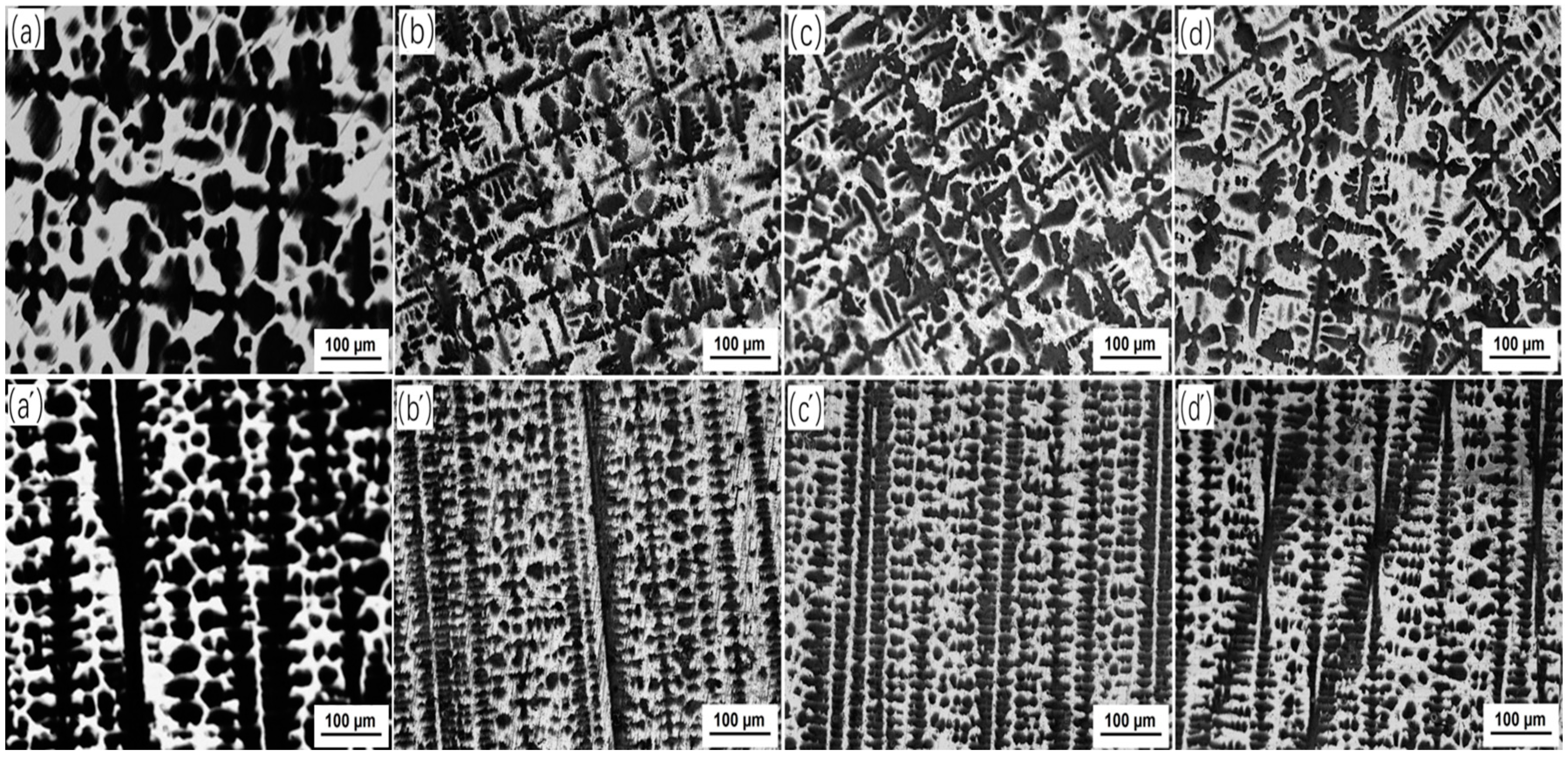
The directionally solidified MnCuNiFe alloy consists of dark dendrites and surrounding white interdendritic spacings. Applying magnetic field during the directional solidification of Mn-Cu based alloy can modulate the crystal orientation, and significantly refine the dendrite microstructure by about 2.6 times that without magnetic field.
(2)
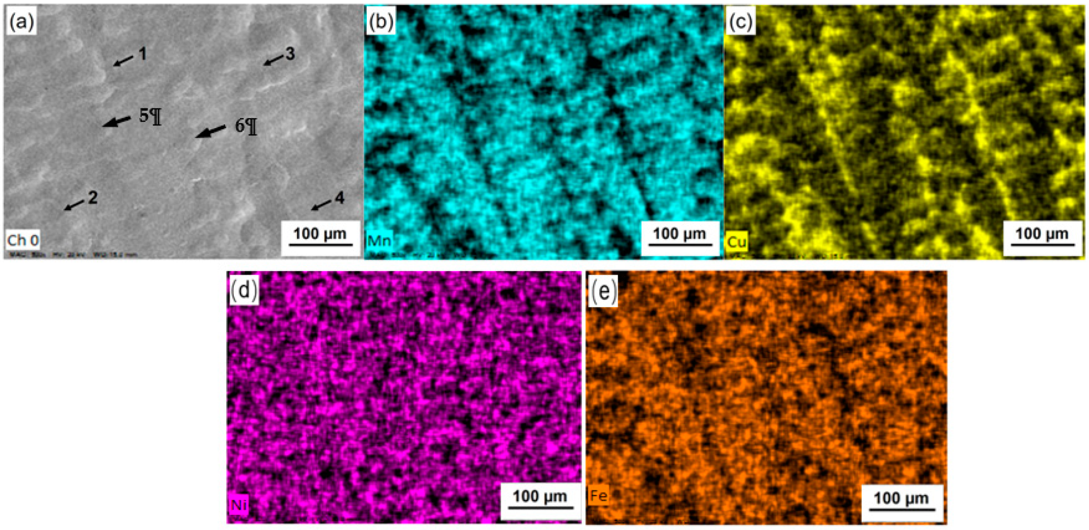
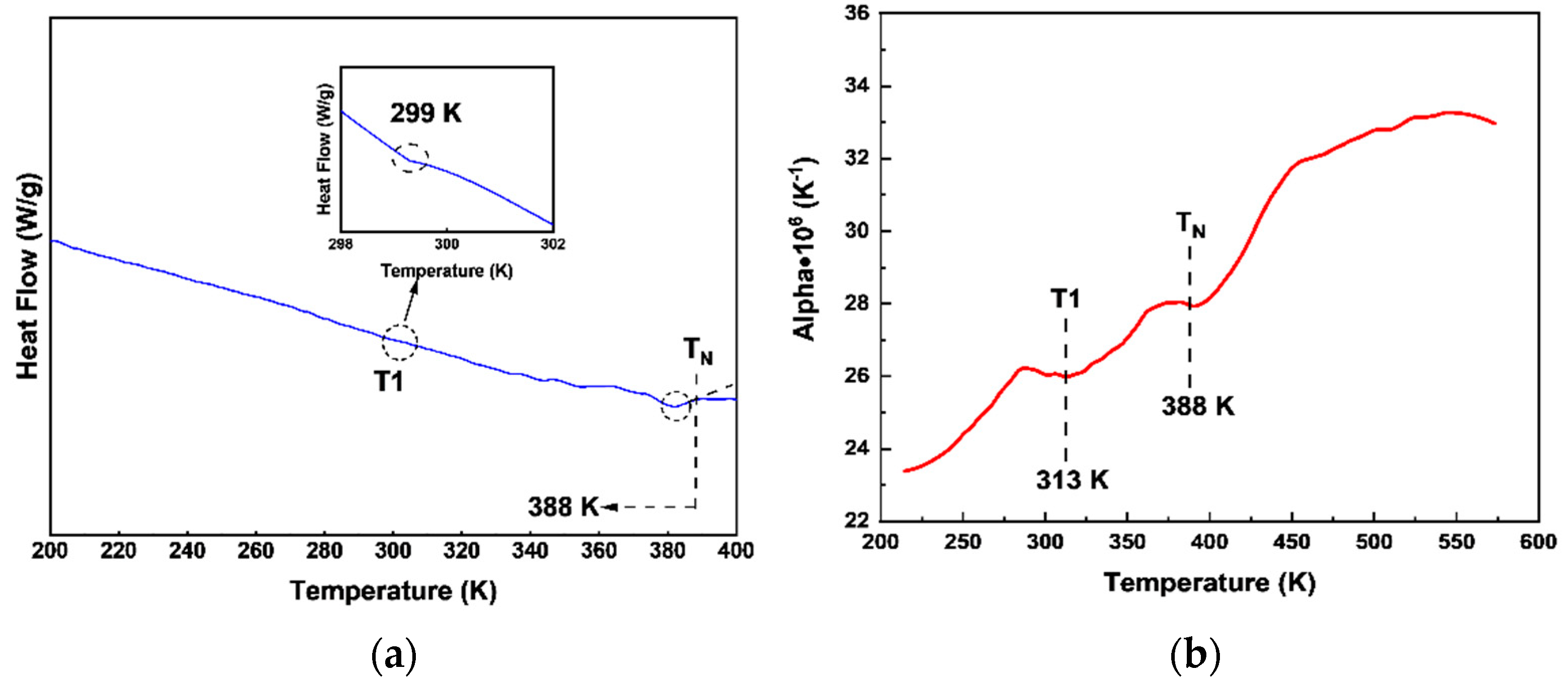
In comparison with directionally solidified MnCuNiFe alloy without magnetic field, the interdendritic regions average Ni content of the alloy is increased 33% by directional solidification under high magnetic field. The enrichment of Ni element induces the occurrence of fct1 → fcc martensitic transformation at about 300 K.
(3)
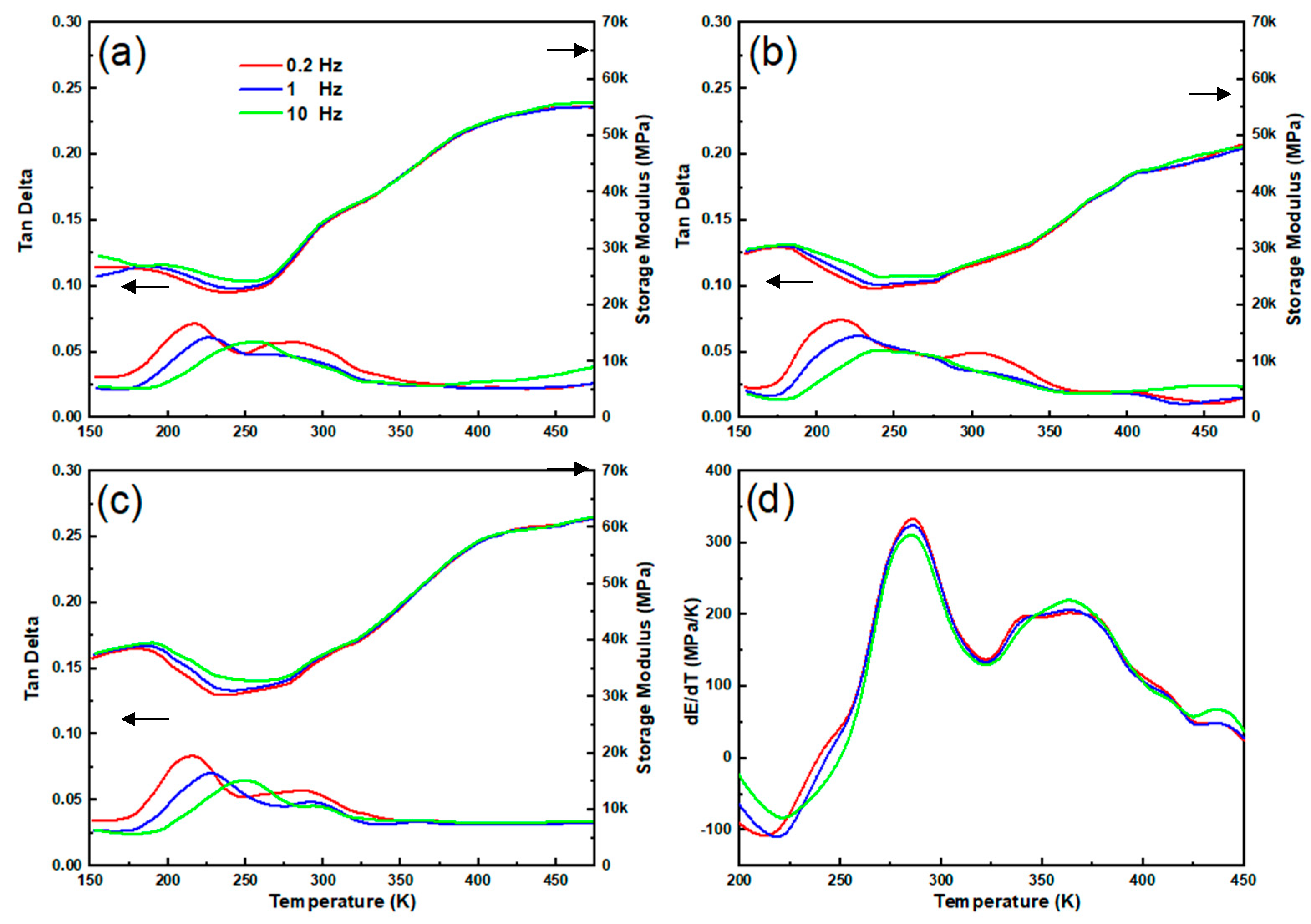
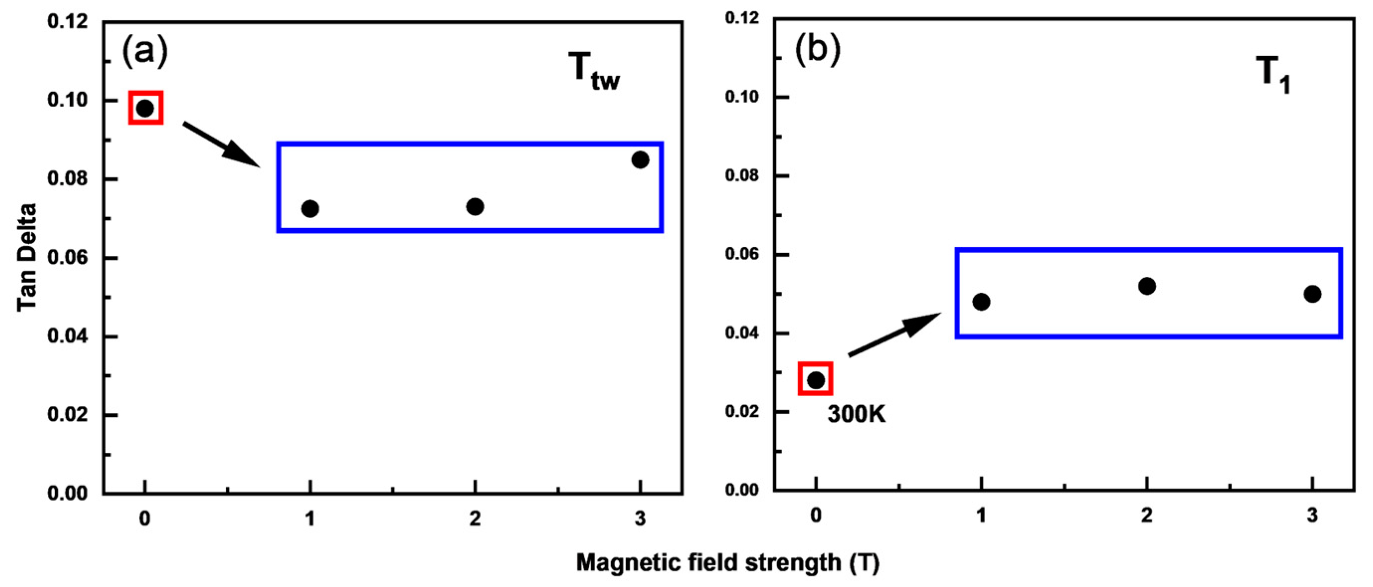
With the increase of magnetic field, the twin boundary IF of the alloy gradually increases from 0.0725 to 0.0848 at 0.2 Hz. The magnetic field reduces the twin boundary IF a little, while the fct1 → fcc martensitic transformation produces a second IF peak in the temperature region around 300 K, and enables the alloy to maintain continuous high damping performance in a wide temperature range from 200 K to 320 K.

Author Contributions

Conceptualization, Q.T.; Methodology, Q.T., W.X. and Z.R.; Validation, D.W., H.N. and Q.T.; Formal analysis, D.W., H.N. and Q.T.; Investigation, S.Z.; D.W. and H.N.; Data curation, S.Z.; D.W. and H.N.; Writing—original draft preparation, S.Z. and D.W.; Writing—review and editing, S.Z.; D.W., H.N. and Q.T.; Visualization, S.Z.; D.W., H.N. and Q.T.; Supervision, Q.T.; Project administration, Q.T.; Funding acquisition, Q.T. All authors have read and agreed to the published version of the manuscript.

Funding

This research received no external funding.

Conflicts of Interest

The authors declare no conflict of interest.

References

  1. Ma, J.X.; Wei, Q.; Wei, F.A.; Le, T.H.; Wang, J.H.; Jin, P.P. Temperature damping characteristics of Mg-3Al-1Zn-xSn magnesium alloy. Spec. Cast. Nonferrous Alloy 2020, 40, 1405–1410. [Google Scholar]
  2. Yang, Z.X.; Jiang, H.J.; Liu, C.Y.; Qing, F.C.; Huang, H.F. Effect of friction stir processing on microstructure and damping capacity of the ZL108 aluminum alloy. Spec. Cast. Nonferrous Alloy 2018, 38, 1257–1261. [Google Scholar]
  3. Lu, R.P.; Yao, K.Y.; Li, K.; Jiao, K.; Zhao, Y.H.; Hou, H. Influences of trace aluminum on the damping performance of magnesium alloy. Spec. Cast. Nonferrous Alloy 2020, 40, 1195–1198. [Google Scholar]
  4. Zhang, S.B.; Jiang, Z.C.; Tian, Q.C.; Li, C.J.; Ren, Z.M. Effect of magnetic field heat treatment on damping capacity of M2052 alloy. J. Funct. Mater. 2020, 51, 10138–10144. [Google Scholar]
  5. Zhang, S.B.; Jiang, Z.C.; Tian, Q.C. Damping Performance of Material Candidates for Service at 350K. Solid State Phenom. 2021, 315, 43–49. [Google Scholar] [CrossRef]
  6. Zhang, S.B.; Tian, Q.C. Parent-phase twinning induced ultra-high damping capacity of Mn-20Cu-5Ni-2Fe alloy under directional solidification process. Intermetallics 2021, 138, 107343. [Google Scholar] [CrossRef]
  7. Zhao, Y.; Su, H.J.; Zhang, J.; Liu, L.; Fu, H.Z. Recent progress on directionally solidification of nickel-based superalloys with magnetic field. Mater. Mech. Eng. 2021, 45, 1–7+44. [Google Scholar]
  8. Ren, Z.M.; Jin, F.W. Progress in applications of strong magnetic field in processing metallic materials. J. Shanghai Univ. (Nat. Sci.) 2008, 14, 446–455. [Google Scholar]
  9. Zhang, S.B.; Tian, Q.C.; Qi, Y.S.; Li, Y.C.; Li, C.J. Tuning ultra-high damping capacity of Mn-Cu alloy to fit wide-range service temperature. Mater. Sci. Technol. 2022, 38, 299–307. [Google Scholar] [CrossRef]
  10. Li, M.; Ren, W.L.; Ren, Z.M.; Li, X.; Zhong, Y.B.; Deng, K. Effect of high longitudinal magnetic field on interface stability and morphology of directionally solidified Al-0.85%Cu alloy. Chin. J. Nonferrous Met. 2011, 21, 1292–1298. [Google Scholar]
  11. Zhong, H.; Li, C.J.; Wang, J.; Ren, Z.M.; Zhong, Y.B.; Xuan, W.D. Effect of a high static magnetic field on microsegregation of directionally solidified Al-4.5Cu alloy. Acta Metall. Sin. 2016, 52, 575–582. [Google Scholar]
  12. Hou, L.; Dai, Y.C.; Fautrelle, Y.; Li, Z.B.; Ren, Z.M.; Esling, C.; Li, X. Evolution of microstructure and microsegregation in Ni-Mn-Ga alloys directionally solidified under axial magnetic field. J. Alloy. Compd. 2018, 758, 54–61. [Google Scholar] [CrossRef]
  13. Zhong, H.; Ren, Z.M.; Li, C.J.; Zhong, Y.B.; Xuan, W.D.; Wang, Q.L. Texture formation and grain boundary characteristic of Al-4.5Cu alloys directionally solidified under high magnetic field. Acta Metall. Sin. 2015, 51, 473–482. [Google Scholar]
  14. Xuan, W.D.; Ren, Z.M.; Li, C.J.; Ren, W.L.; Chen, C.; Yu, Z. Effect of longitudinal magnetic field on the microstructure of directionally solidified superalloy DZ417G with different sizes. Acta Metall. Sin. 2012, 48, 629–635. [Google Scholar] [CrossRef]
  15. Wang, D.W.; Tian, Q.C.; Niu, H.K. Damping characteristics of composite phase transformation behavior of directionally solidified MnNi alloy. Aerosp. Mater. 2022, 42, 81–90. [Google Scholar]
  16. Wang, D.W.; Tian, Q.C. Phase transformation characteristics and ultra high damping behavior of directionally solidified MnNi alloy. Nonferrous Met. Eng. 2022, 12, 31–38. [Google Scholar]
  17. Jiang, Z.C.; Hou, L.; Tian, Q.C.; Ren, W.L.; Ren, Z.M. Polymorphic microstructure of a MnCu damping alloy solidified under magnetic field. Mater. Res. Express 2019, 6, 0865h2. [Google Scholar] [CrossRef]
  18. Jiang, Z.C.; Zhang, S.B.; Tian, Q.C.; Ji, P.G.; Yin, F.X. Phenomenological representation of mechanical spectroscopy of high damping MnCuNiFe alloy. Mater. Sci. Technol. 2020, 36, 743–749. [Google Scholar] [CrossRef]
Figure 1. Microstructures of cross (ad) and longitudinal (a′d′) sections of directionally solidified MnCuNiFe alloy under different magnetic fields: (a,a′) 0T [6], (b,b′) 1T, (c,c′) 2T, (d,d′) 3T.
Metals 13 00006 g001
Figure 2. Longitudinal sectional EDS map scan of 1T specimen: (a) SEM image, (b) Mn, (c) Cu, (d) Ni and (e) Fe (the number in Figure 2a indicates the position of EDS point analysis).
Metals 13 00006 g002
Figure 3. TEM microstructure directionally solidified MnCuNiFe alloy under 1T magnetic field, (a,b) twin microstructures, and (c,d) high resolution images.
Metals 13 00006 g003
Figure 4. XRD patterns of directionally solidified MnCuNiFe specimens under different magnetic fields, where specimen 0T was reprinted from Ref. [6].
Metals 13 00006 g004
Figure 5. Phase transformation behavior of 1T specimen, (a) heat flow curve, where the inset is the enlarged picture at 299 K, and (b) thermal expansion curve.
Metals 13 00006 g005
Figure 6. Dynamic mechanical spectra of directionally solidified MnCuNiFe specimens under 3-point bending mode: (a) 1T, (b) 2T, and (c) 3T, where the arrows are pointed to two Y-axes of Tan Delta and Storage modulus, respectively, and (d) dE/dT of Figure 6a.
Metals 13 00006 g006
Figure 7. IF peak value dependence of magnetic field at 0.2 Hz, (a) twin boundary IF, (b) IF peak of magnetic field induced phase transformation (0T data from reference [9]).
Metals 13 00006 g007
Table 1. EDS point analysis results of the selected positions in Figure 2a.
PositionsMn (at.%)Cu (at.%)Ni (at.%)Fe (at.%)
167.3624.716.231.70
268.7223.605.691.99
375.1816.715.252.86
476.6515.125.003.23
580.8911.263.854.00
678.8413.624.013.53
Disclaimer/Publisher’s Note: The statements, opinions and data contained in all publications are solely those of the individual author(s) and contributor(s) and not of MDPI and/or the editor(s). MDPI and/or the editor(s) disclaim responsibility for any injury to people or property resulting from any ideas, methods, instructions or products referred to in the content.

