Article

Rapid Spheroidizing Annealing via Combining Warm Deformation with Divorced Eutectoid Transformation in M50 Steel

1
School of Materials Science and Engineering, Wuhan University of Technology, Wuhan 430070, China
2
Hubei Key Laboratory of Advanced Technology for Automotive Components, Wuhan 430070, China
3
Hubei Engineering Research Center for Green Precision Material Forming, Wuhan 430070, China
4
School of Automotive Engineering, Wuhan University of Technology, Wuhan 430070, China
*
Authors to whom correspondence should be addressed.
Metals 2022, 12(2), 359; https://doi.org/10.3390/met12020359
Submission received: 29 January 2022 / Revised: 17 February 2022 / Accepted: 17 February 2022 / Published: 20 February 2022

Abstract

:
In this work, a novel routine to realize the rapid spheroidizing annealing (SA) process has been proposed in M50 steel via combining warm deformation (WD) and divorced eutectoid transformation (DET). In this process, the sample is first subjected to partial austenitizing to realize the partial dissolution of carbides, then slowly cooled to DET temperature for WD. Finally, the sample is slowly cooled to below the eutectoid transformation temperature to complete the SA. The results show that an excellent spheroidized microstructure can be obtained via the rapid SA process within 2 h. The finest spheroidized carbide (0.295 μm), as well as an appropriate hardness (217 HV), is achieved when the WD and DET processes are conducted at 760 °C. This should be attributed to that the WD not only accelerates the DET but also can break the primary carbides, leading to the uniformly distributed and refined carbides. In addition, the proposed WD that realizes rapid SA shows the excellent roundness of spheroidized carbides compared with the traditional cold/hot deformation which needs a long-term SA process. This work provides a highly efficient routine to simultaneously realize the SA and shape forming, which is of great engineering significance for the manufacturing of bearings.

1. Introduction

M50 bearing steel, as a kind of molybdenum steel, exhibits excellent hardness and wear resistance under the high-temperature environment, so it is widely used in the manufacture of aerospace engine bearings [1,2]. Plastic deformation is an inevitable process for M50 steel for the forming of bearing rings, in which the ring rolling technology has been extensively applied in aviation M50 bearing steel. It has been demonstrated to show the advantages of high efficiency, excellent streamlines and fatigue properties compared with other processing methods [3]. In recent years, the hot rolling (higher than austenitization-temperature) and cold rolling (at ambient-temperature) are widely used in the forming of bearing rings in M50 steel [4,5].
Hot rolling as a thermoplastic process that shows superior plasticity, usually results in coarse grain due to long-term insulation at high-temperature. Meanwhile, the microstructure after hot rolling is mainly composed of martensite in M50 steel, which needs to be subjected to the spheroidizing annealing (SA) for subsequent cutting [6]. As for the cold rolling, the grain refinement [7,8] and solution strengthening effect can be achieved to improve the strength and toughness of bearing steels [9]. Nevertheless, not only does it need SA to improve plasticity before cold rolling, but also stress relief annealing (SRA) is necessary to eliminate residual stress after cold rolling. From the above analysis, it can be concluded that SA is an indispensable process, whether for hot rolling or cold rolling. The traditional SA is time-consuming and energy-consuming, and the SA of M50 steel even takes more than 30 h, which leads to an obvious rise in production cost. To reduce the time-cost of annealing process, much effort has been made to develop the new method to realize the spheroidization of bearing steel in a shorter time [10]. Some researchers found that the divorced eutectoid transformation (DET) could directly form the spherical pearlite [11,12]. The principle of DET was that a large number of undissolved carbides remained in the original austenite through incomplete austenitization. The carbide precipitated at a temperature higher than eutectoid transformation (ET) would adhere to the undissolved carbides, thereby promoting the spherical growth of undissolved particles [13]. By applying the DET process in GCr15 steel, Chen et al. [14] reduced the annealing time from 10–16 h to around 2–3 h.
Recently, it has also been found that the deformation process could promote the spheroidization with slight increase in hardness [15]. Huang et al. [16] suggested that the refinement of granular cementite and grain were both achieved in 65Mn steel when the warm extrusion was subjected at 650 °C for 20 min. Since the deformation can accelerate the DET process and refine the microstructure, some scholars combined DET with warm deformation (WD) to simultaneously realize the SA and shape forming. Our previous work indicated that the fine and uniform spheroidized carbides could be obtained by combining DET and WD in GCr15 steel [17,18]. In addition, Han et al. [19,20] investigated the impact of deformation conditions on the spheroidizing process in GCr15, and the optimum deformation temperature was determined at 800 °C with a total reduction of 30%. The above findings demonstrate the WD process is effective in carbide spheroidization by utilizing the DET. However, the microstructure and hardness evolution during the whole process have not been studied. As for the high-alloyed M50 containing primary carbides, the microstructure evolution behavior and spheroidization mechanism under the combining process of WD and DET remain unclear.
In this work, the rapid SA process of M50 steel is achieved via combining WD with DET. The evolution behaviors of microstructure including primary carbides during the whole process have been discussed. The influence of deformation temperatures on the SA effect is also studied. In order to verify the effect of proposed rapid SA, the traditional processes that combined cold/hot deformation with long-term isothermal SA are also compared.

2. Materials and Methods

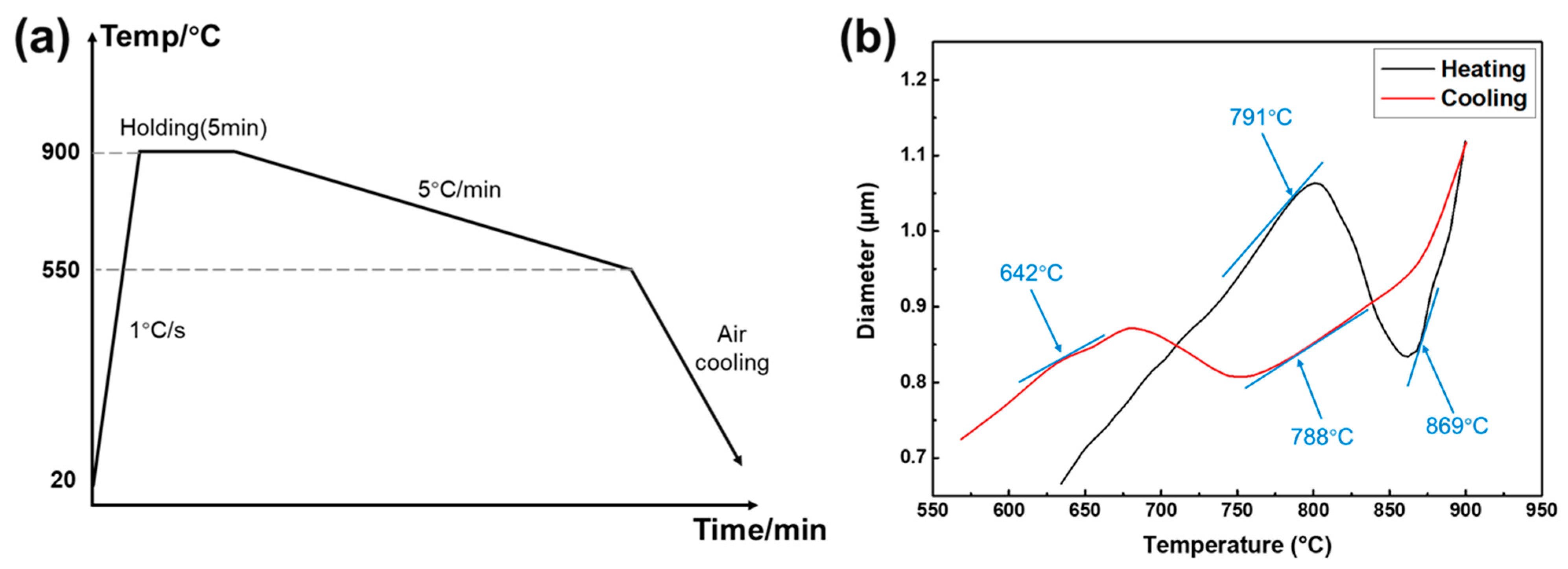
2.1. Material and Determination of Test Parameters

Vacuum induction and vacuum arc remelting are used for melting M50 bearing steel. The ingots are forged into blanks and then conducted to SA. The initial material used in this work is spheroidized annealed M50 steel. The chemical composition of the selected steel is presented in Table 1. To determine the phase transformation temperature of M50 bearing steel, the thermal expansion test was carried out using an MMS-200 thermal simulator testing machine, in which the schematic illustration has been presented in Figure 1a. The sample was first heated to 900 °C for 5 min at the rate of 1 °C/s, and followed by cooled to 550 °C at the rate of 5 °C/min. The measured expansion curves are displayed in Figure 1b. It was determined by the tangent method that the transformation temperature from ferrite into austenite ranges from 791 °C to 869 °C during heating, while the temperature ranges from 788 °C to 642 °C for the transformation from austenite into ferrite during cooling. From the thermal expansion results, the DET and ET will occur during the temperature range of pearlite transformation (from 788 °C to 642 °C).
To obtain the accurate temperature range of DET, the samples were heated to 860 °C for 30 min in the resistance furnace (for partial austenitization) and then, respectively, cooled to different temperatures (780, 760, 740, 720, 700, 680, 650 °C). After holding for 30 min, the samples were directly water-cooled for microstructure observation. Figure 2 shows the microstructure of the samples subjected to pearlite transformation at different holding temperatures. It can be seen that the microstructure is mainly composed of spherical carbides for the samples at the holding temperature from 780 °C to 700 °C, while there are strip carbides in the matrix for the samples at the holding temperature 680 °C to 650 °C. In addition, the hardness results are shown in Figure 3 where it can be seen that with the decrease in holding temperature, the hardness decreases first and then increases. The microstructure and hardness results together confirm that the upper temperature range is dominated by DET and the lower temperature range is dominated by ET in the whole temperature range of pearlite transformation [21]. In this work, the WD is selected at the DET temperature ranges. Considering the finer carbides and lower hardness for the holding temperature ranged from 720 °C to 760 °C, the experimental deformation temperature is determined to 720 °C, 740 °C, and 760 °C.

2.2. Experimental and Characterization Methods

To verify the spheroidization effect of the proposed WD process that combines with SA processes, the cold deformation (CD)/hot deformation (HD) that combines with SA process was also carried out for comparison as illustrated in Figure 4.
(1)
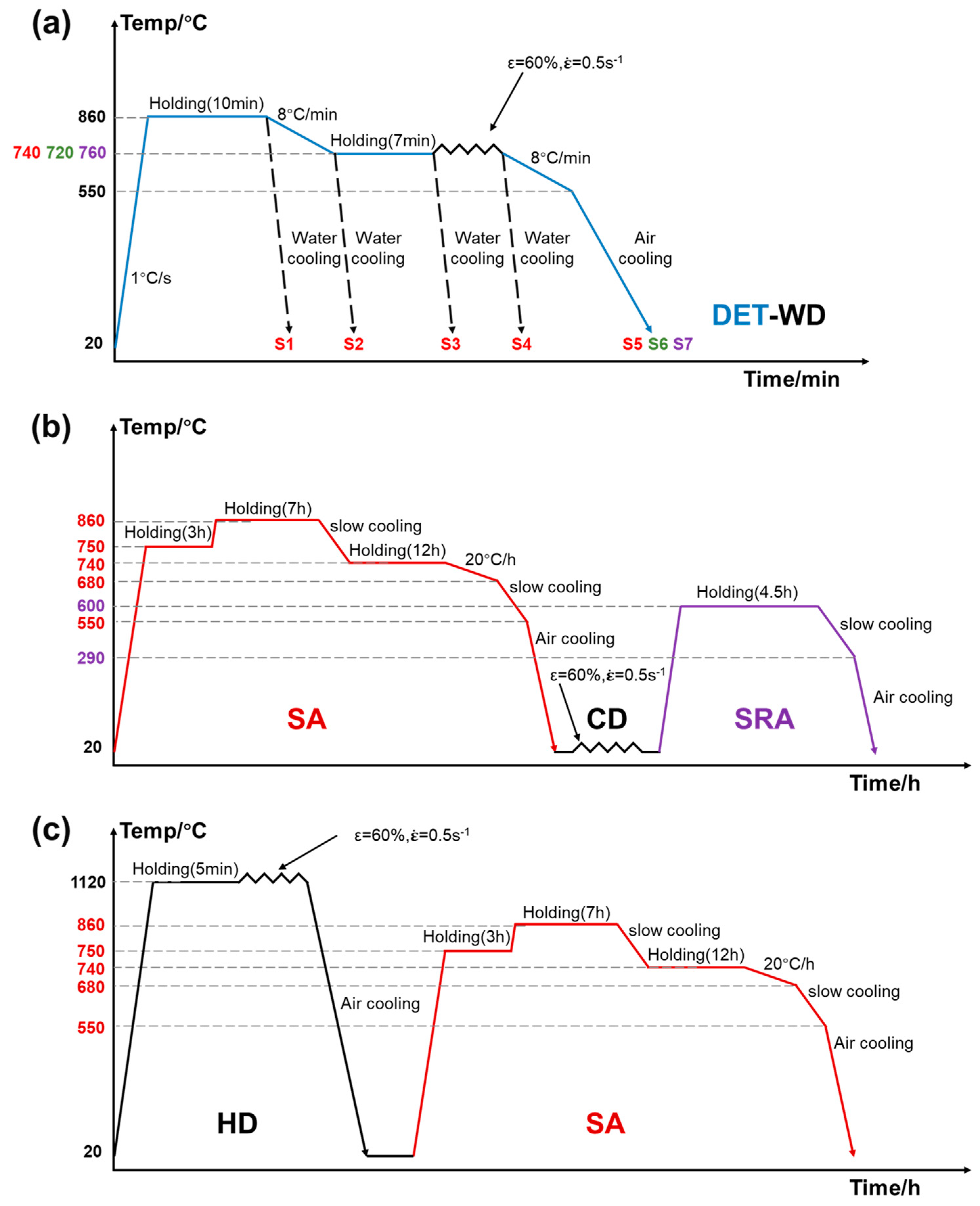
The WD process that combines with SA process (DET-WD): the samples were first heated to 860 °C for 10 min and then slowly cooled to DET temperature (720 °C, 740 °C, and 760 °C). During this stage, the WD was conducted with a 60% reduction at the rate of 0.5 s−1. After deformation, the samples were slowly cooled to 550 °C and finally subjected to air-cooling below 550 °C;
(2)
The CD process that combines with SA process (SA-CD): the samples were first subjected to the traditional isothermal SA process before CD as detailed in Figure 4b. After SA process, the sample was deformed with a 60% reduction by the press at room-temperature. Lastly, the SRA process is carried out as based on the standard manufacturing process of bearing rings;
(3)
The HD process that combines with SA process (HD-SA): the samples were heated to 1120 °C at the rate of 5 °C/s. After holding for 5 min, the samples were deformed with a 60% reduction at the same rate of 0.5 s−1. After that, the samples were put out from the furnace for air-cooling and the traditional isothermal SA process is conducted at last.
To investigate the carbide evolution during the DET-WD process, the samples at different stages were directly water-cooled to room-temperature as referred by S1–S5 samples. Meanwhile, the effect of different deformation temperatures on the spheroidization effect was also investigated as referred by S5–S7 samples.
The microstructure was observed by the optical microscope (OM) and scanning electron microscope (SEM). The samples were cut along the axial direction, finely ground, and then polished. Subsequently, the samples for the microstructure observation were etched with 4% nital for 25 s. The roundness, diameter, aspect ratio, area, and perimeter of carbides were counted by Image-Pro Plus (IPP) according to the SEM picture. The SEM pictures of each sample were selected at three fields of vision, and the statistical results were taken as the average value. In this work, the aspect ratio is equivalent to the ratio between major axis and minor axis of the carbide, while the carbide with an aspect ratio higher than 2 is defined as strip carbide. The diameter of the carbide is calculated through the area, while the carbide with a diameter greater than 1 μm is defined as large-sized carbide. The roundness which can reflect the spheroidization degree of carbides is calculated by:
R = C 2 / ( 4 π S )
where R, C and S represent the roundness, perimeter and area of carbide, respectively.
In addition, the microstructure was also characterized by the electron backscattering diffraction (EBSD). The samples used for EBSD analysis were firstly mechanically ground and then polished with electrolytic polishing. The hardness was tested by a micro-hardness tester (HV-1000A) with a load of 0.2 kg and a dwell time of 10 s. Noted that each sample was tested at 8 points.
To identify the type of carbide, the carbide powder of the initial material and S1 was prepared by electrolytic extraction. The electrolyte was composed of 4 g citric acid, 10 mL hydrochloric acid, and 125 mL methanol. The electrolyte temperature was set as 5 °C, with the current density of 0.030 A∙cm−2. After 8 h electrolysis, the carbide powder was obtained by the circulating water vacuum pump and the filter device equipped with PVDF filter membrane with pore diameter of 0.1 μm. The X-ray diffraction (XRD) tests were carried out for the analysis of carbide type and dislocation density in the samples. The samples used for XRD analysis were ground using 2000 grit sandpaper and then mechanically polished. The scanning angle of XRD spectrum was from 35° to 120° at a slow speed of 1 °/min. The dislocation density was evaluated by the Williamson-Hall (WH) method [22]:
ρ = 1.44 ( ε b ) 2
where ρ and b represent the dislocation density of ferrite and the magnitude of Burgers vector (b = 0.248 nm), respectively. Additionally, ε is a parameter indicating the microscopic distortion and can be determined as the slope of the fitting curve. In this fitted curve, the x-axis value of scattering points can be expressed by:
X h k l = 2 sin θ h k l / λ
The y-axis value can be calculated by:
Y h k l = β h k l cos θ h k l / λ
where β and λ represent the full width at half maximum (FWHM) and wavelength of X-ray, respectively. The value of λ for Cu radiation is 0.15405 nm. In addition, θ indicates the diffraction angle.

3. Results and Discussion

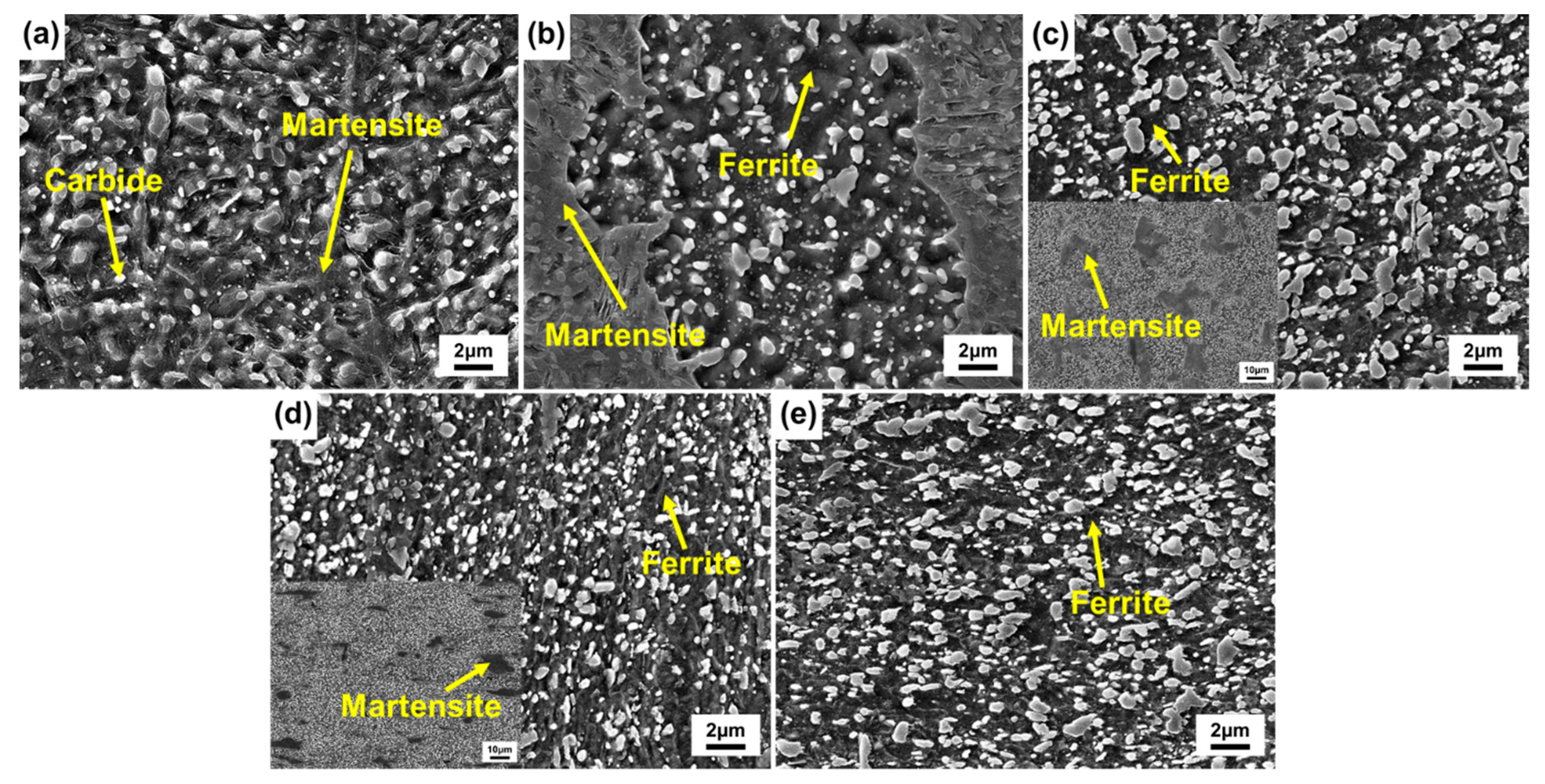
3.1. Microstructure Evolution during the DET-WD Process

The microstructure evolution during the DET-WD process is shown in Figure 5. After austenitization, there are still a large number of undissolved carbides in the matrix presented in Figure 5a. Meanwhile, the martensite is formed due to the water-cooling. As the temperature decreases to the DET temperature, some fine carbides begin to precipitate and the ferrite is formed as shown in Figure 5b. After holding at DET temperature for 7 min, the diameter of carbides gradually increases and strip carbides can be clearly observed. The amount of ferrite increases as well (Figure 5c). After WD, it is clear from Figure 5d that the number of carbides increases while the carbides are significantly refined. After the final air-cooling, the carbides gradually grow up with the whole process completed.
Figure 6 shows the statistical result of carbides during the DET-WD process. As can be seen from Figure 6a, the roundness and diameter of carbides are the smallest after partial austenitization. This could be ascribed to the occurrence of partial dissolution of carbides. After holding at DET temperature, carbides precipitate and adhere to the undissolved carbides, thereby leading to a slight increase in the diameter of carbides. Furthermore, the diameter and roundness of carbides decrease for S4 sample, demonstrating that the WD can effectively refine the carbides with the increase in hardness. From Figure 6b, the proportion of strip carbides is obviously decreased by 18.0% after cooling to DET temperature. However, the proportion of strip carbides is increased after holding for 7 min, which means that the ET also occurs in this process. Afterwards, the large-sized carbides exhibit the same trend as the strip carbides. It should be noted that the large-sized carbides nearly disappear after WD (in S4 sample), thus verifying the obvious broken effect of carbides induced by deformation.
In the whole process, the carbides are first dissolved and then precipitated. The XRD patterns of carbide powder in the initial material and the sample after holding at 860 °C for 10 min are shown in Figure 7. The M2C, MC, M6C, M23C6, and M7C3 alloy carbides can be detected both in the initial and partially austenitized samples. This indicates that the carbide types have not been changed after this process.
The primary carbides precipitated in eutectic reaction have a great influence on the properties of materials. The OM and SEM micrographs of primary carbides in the DET-WD process are displayed in Figure 8. As can be seen from Figure 8a, the primary carbides in the initial material are distributed unevenly in strips along the same direction. The distribution of primary carbides in Figure 8d is completely different and becomes very uniform due to the WD that significantly changes the distribution of primary carbides. In addition, there are a large number of voids around the primary carbides as can be seen from Figure 8b, which could be caused by the blank forging. After the DET-WD process, the voids are nearly disappeared from Figure 8e. In the SEM picture with higher multiples (Figure 8f), there are some tiny voids around the primary carbides, while the number and area of voids are greatly reduced compared with that before the DET-WD process. The result indicates that the voids generated during blank forging may be effectively repaired after the DET-WD process. Moreover, the primary carbides in Figure 8c are entire, instead, there are broken primary carbides in Figure 8f, which indicates that the WD leads to the uniform distribution of primary carbides and play a role in crushing and refining primary carbides.
The thermal expansion curve of the DET process is depicted in Figure 9, which can indicate the evolution of ferrite during the whole DET-WD process. From the curve, it can be seen that ferrite begins to transform into austenite at 805 °C during the heating process. Therefore, after holding for 10 min, there is martensite in the water-cooled structure (Figure 5a). The carbon concentration in the structure is uneven due to the partial dissolution of carbides, which is also one of the conditions for the occurrence of DET. It is observed that DET occurs during the cooling. Austenite starts to transform into ferrite at 742 °C. Therefore, there are both martensite and ferrite in Figure 5b. When holding at the DET temperature, austenite continues transforming into ferrite, resulting in the reduced martensite in the water-cooled structure (Figure 5c). The subsequent WD can refine ferrite while breaking carbides. Hence, the fine grain structure can be obtained for the DET-WD process [23]. After the process, there is no martensite in Figure 5e, indicating that the remaining austenite has been completely converted to ferrite at 692 °C.
The change of hardness is affected by both phase transformation and deformation. The water-cooled structure after partial austenitization is composed of martensite, with the hardness of 602 HV. When the sample is cooled to the DET temperature, the carbides spheroidized make the hardness decrease to 546 HV owing to the occurrence of DET. After insulation, austenite transforms into ferrite with low hardness, leading to the hardness decreasing to 235 HV. The hardness is significantly increased to 304 HV for the residual stress caused by WD. Owing to the residual stress partly released in the final cooling, the hardness is decreased to 244 HV.

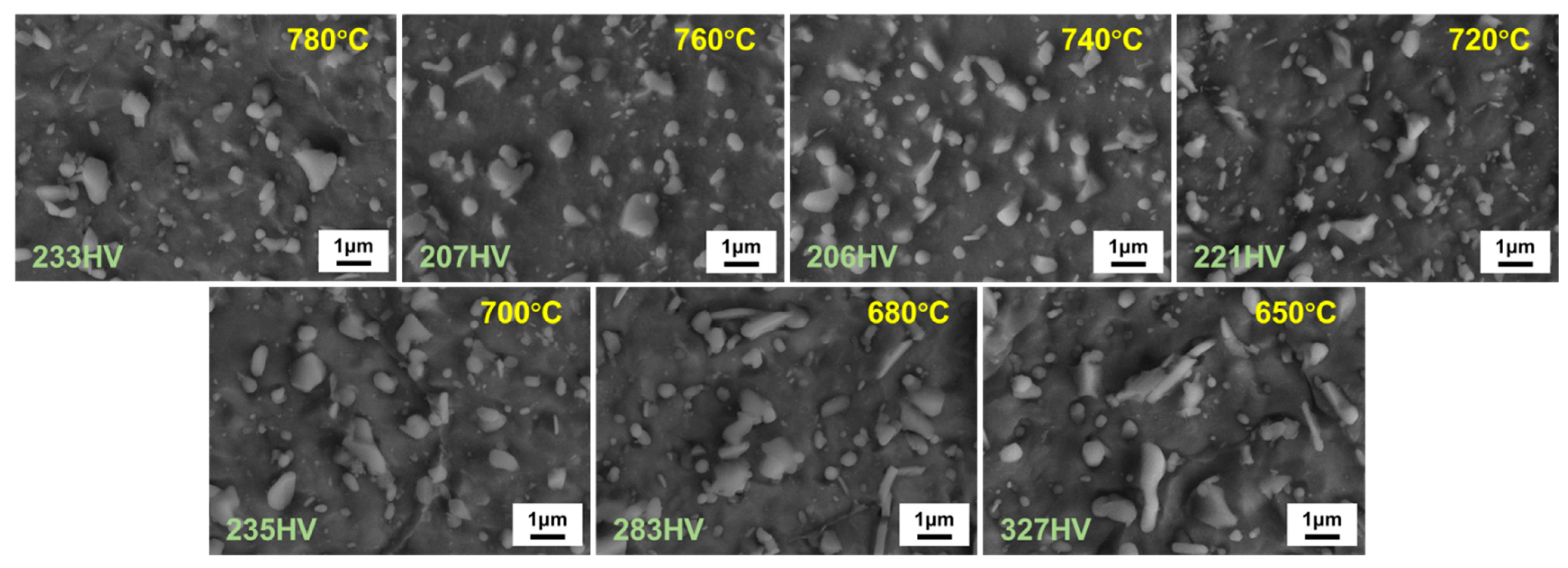
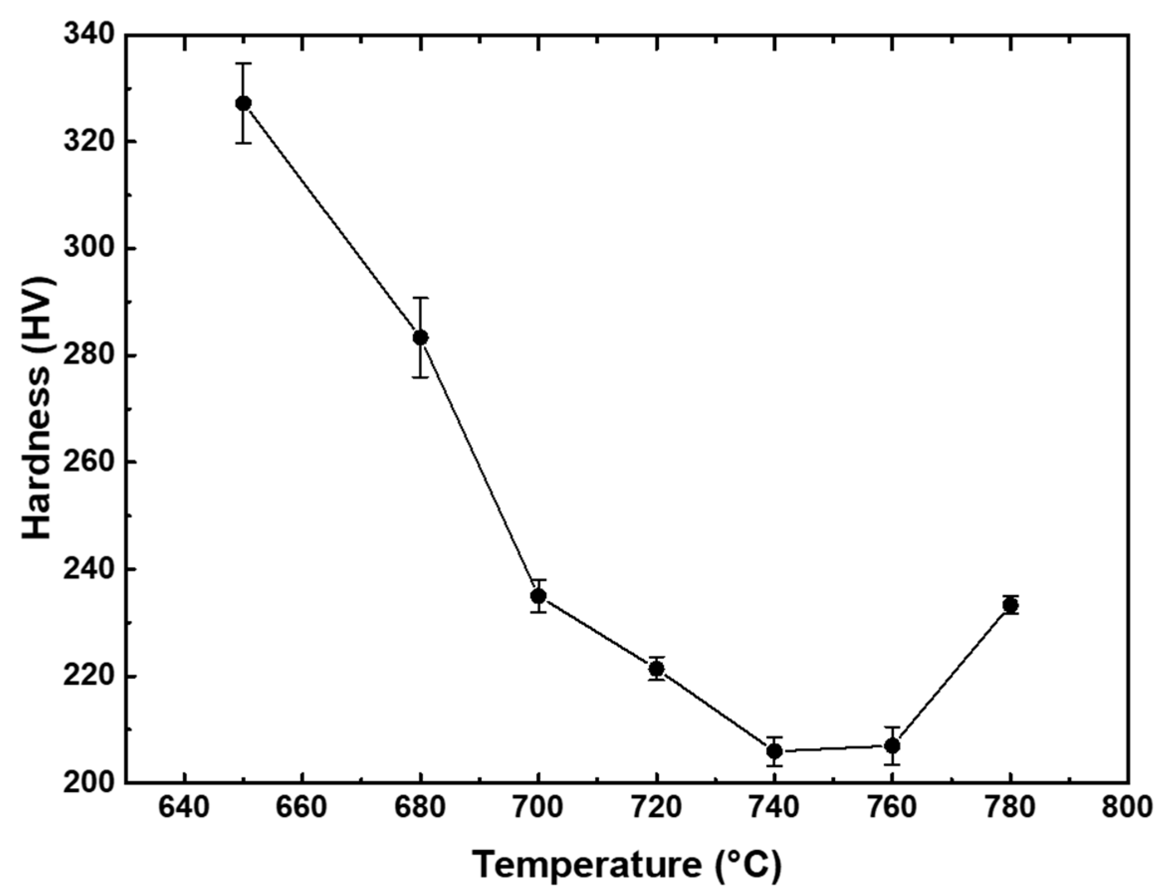
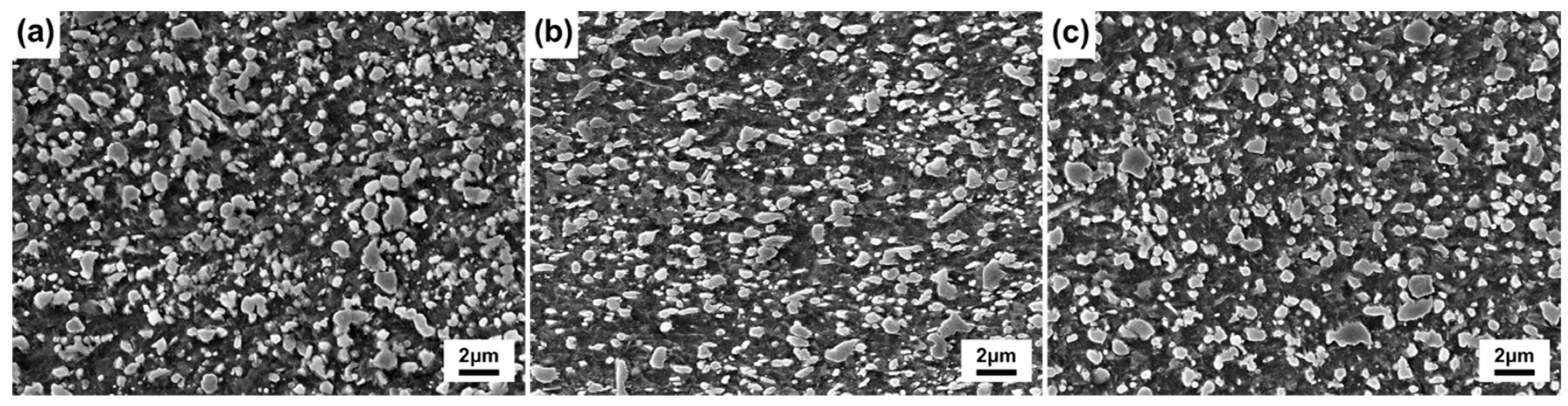
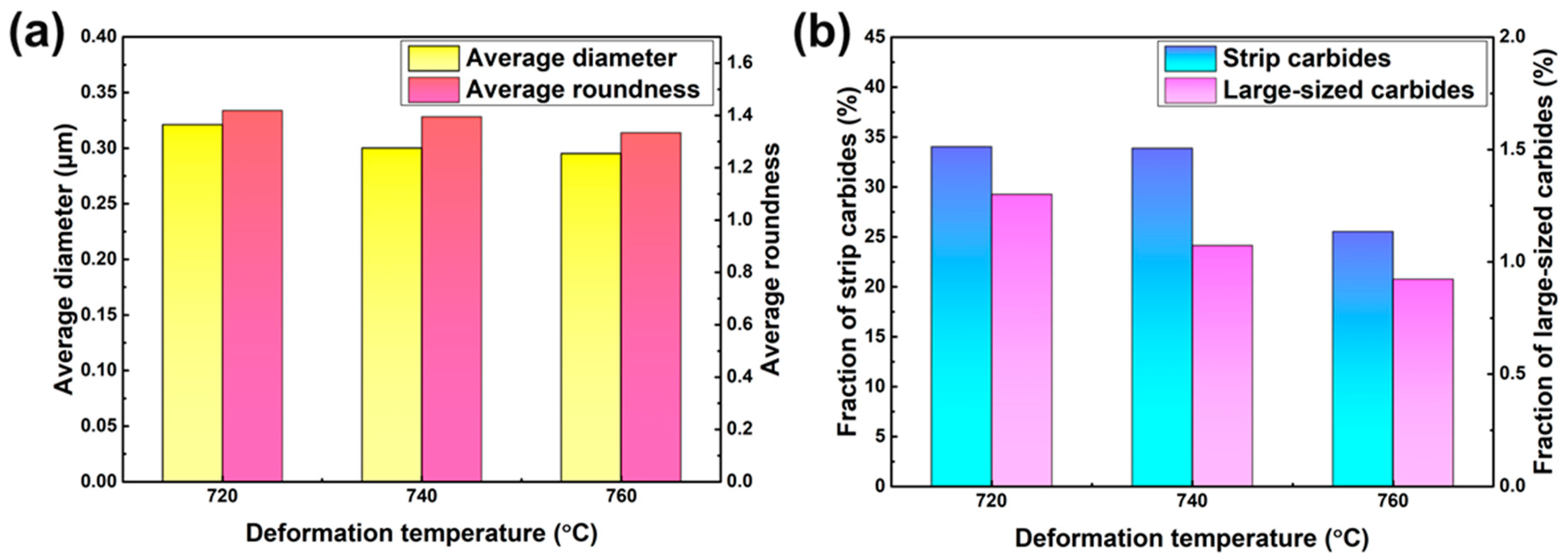
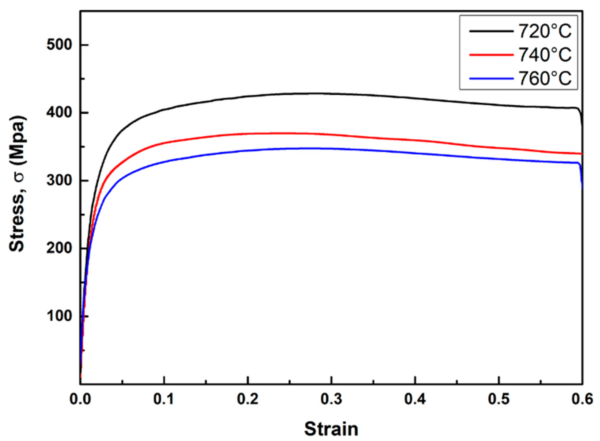
3.2. Effect of Deformation Temperature on the DET-WD Process

The SEM micrographs of the samples at different deformation temperatures in the DET-WD process are displayed in Figure 10. It can be seen that the carbides of the sample deformed at 760 °C are smaller than that of the others and strip carbides are the least.
The statistical result of carbides at different deformation temperatures is shown in Figure 11. With the increase in deformation temperature, the roundness and diameter of carbides are decreased, as well as the proportion of strip carbides and large-sized carbides. It suggests that the spheroidization effect becomes better with the increase in deformation temperature. In the previous DET test, it is found that the carbides obtained by holding at different temperatures are variant. There exists an optimal temperature between 720 °C and 760 °C, which can maximize the degree of DET. Consequently, in the process, the closer the deformation temperature is to the optimal temperature, the higher the proportion of spherical carbides and the better the roundness. The result shows that the spheroidization effect of the sample deformed at 760 °C is the best, with the diameter of 0.295 μm and the roundness of 1.333.
In addition to the effect on the DET, the deformation temperature also affects the deformation stress. The stress–strain curves at different deformation temperatures are depicted in Figure 12. The higher the deformation temperature, the smaller the deformation resistance and the smaller the yield strength. The deformation resistance and yield strength of the sample deformed at 760 °C are the smallest. The deformation resistance and yield strength are usually proportional to the hardness [24]. The hardness of the samples deformed at 720 °C, 740 °C, and 760 °C is 257 HV, 244 HV, and 217 HV. For the joint influence of DET and deformation resistance, the hardness of the sample deformed at 760 °C is obviously lower than that of the others.

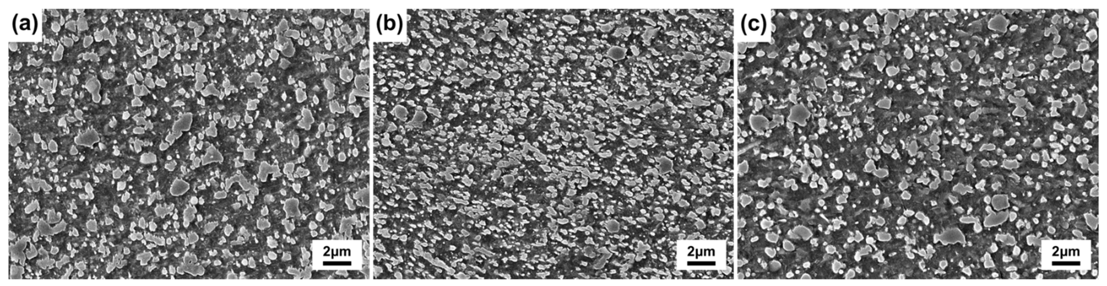
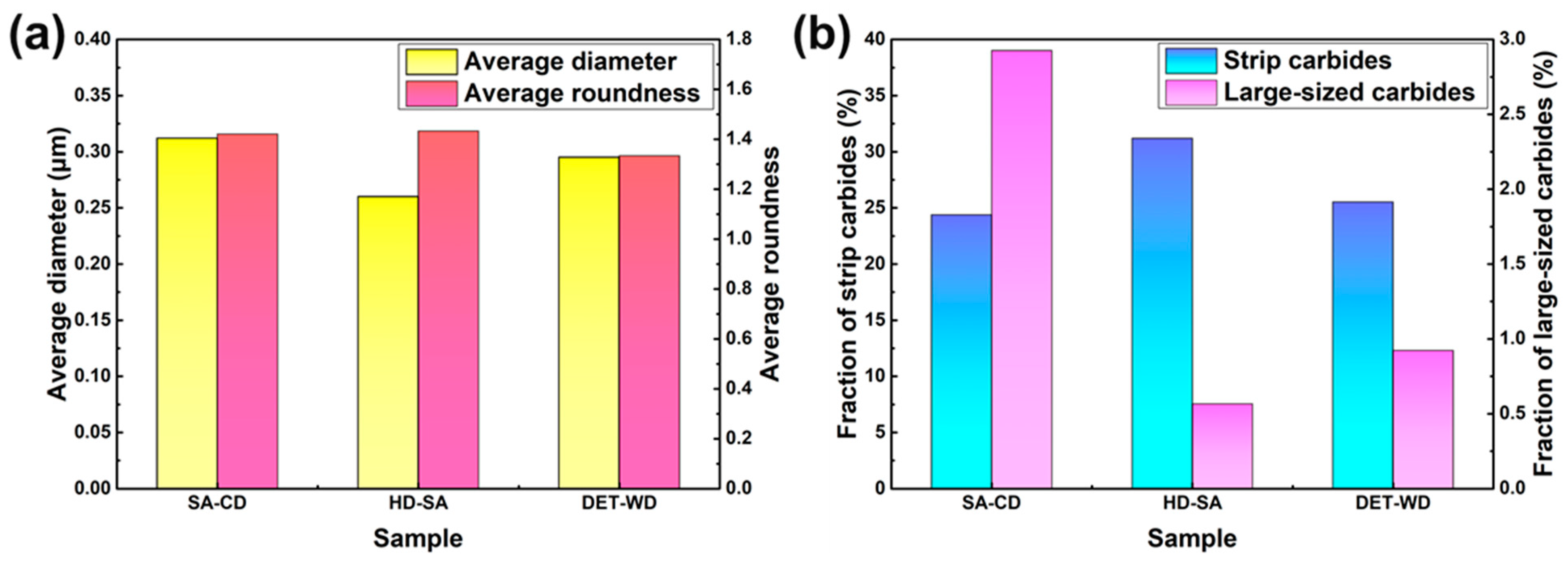
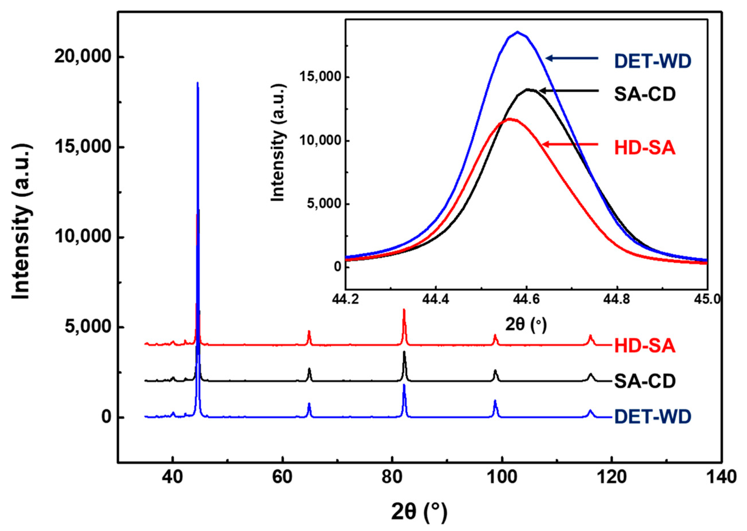
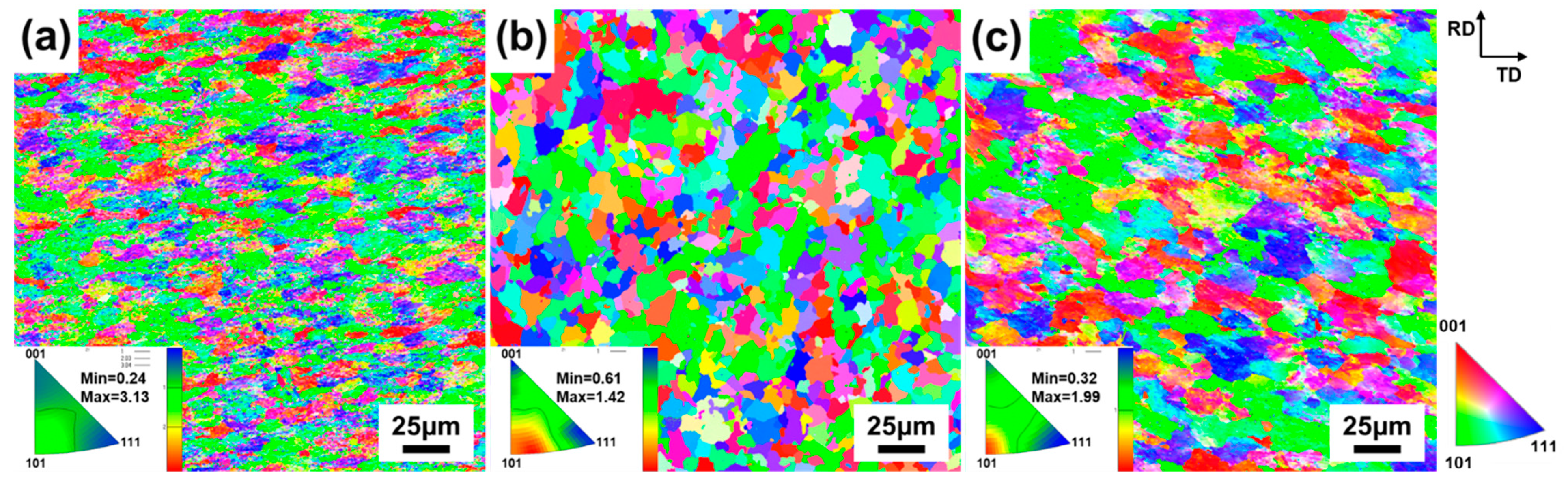
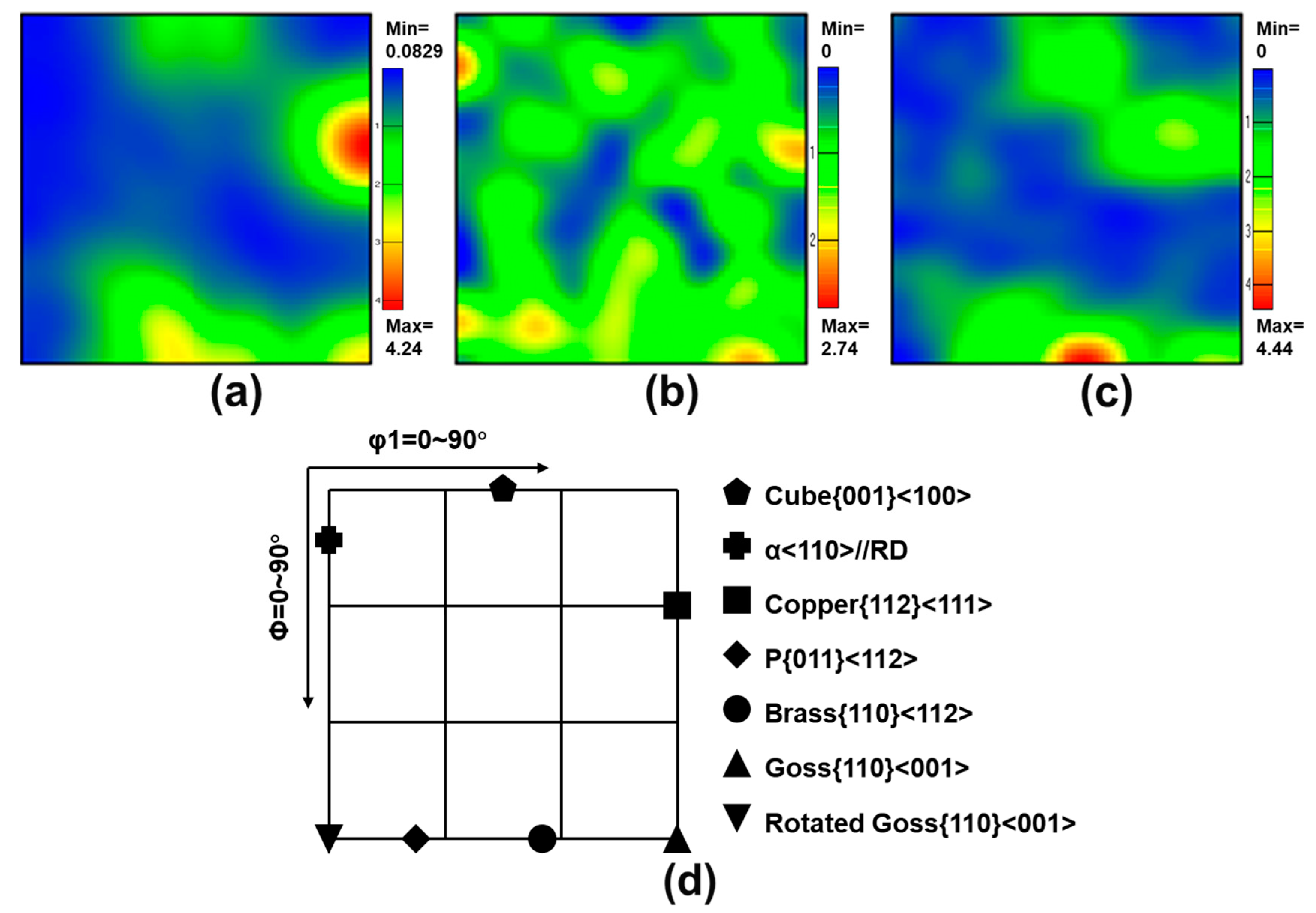
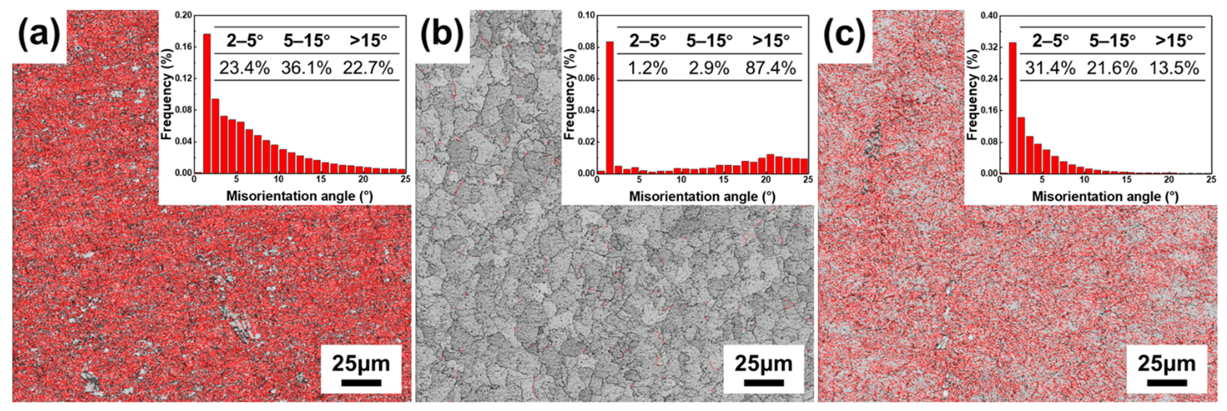
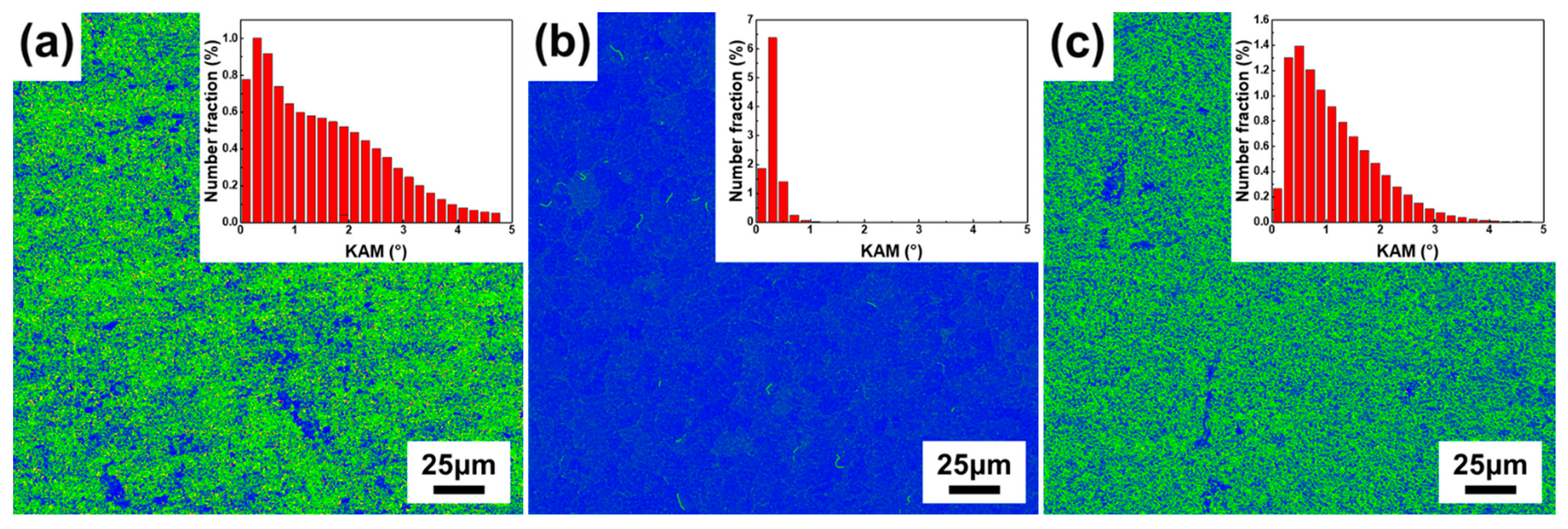
3.3. Comparison of DET-WD, SA-CD and HD-SA Processes

The SEM micrographs of the samples subjected to SA-CD, HD-SA, and DET-WD processes are shown in Figure 13. It is found that there are a lot of large-sized carbides in the SA-CD sample. The carbides of the HD-SA sample are the smallest, while strip carbides are obviously more than the others.
The statistical result of carbides of the samples subjected to different processes are depicted in Figure 14. By comparison of statistical results, it is found that the carbides of the SA-CD sample are the largest with the highest proportion of large-sized carbides. In the SA-CD process, CD breaks the carbides while SRA does not have an effect on carbides. In the HD-SA process and the DET-WD process, the carbides are broken and dissolved by HD and WD, hence the size of carbides in the SA-CD sample is the largest. The carbides of the HD-SA sample are almost dissolved after HD, and then carbides precipitate and are spheroidized after SA. Nevertheless, long-time insulation will increase the proportion of strip carbides and make the average roundness poor. Therefore, the carbides of the HD-SA sample are fine and dispersed, but the proportion of spherical carbides is not high. Instead, in the DET-WD sample, the roundness of carbides is the best and the proportion of spherical carbides is higher than that in the HD-SA sample by 5.7% due to the combination of DET and WD. The fraction of carbides in the samples subjected to the SA-CD, HD-SA, and DET-WD processes are 30.7%, 33.5% and 28.1%, respectively. The carbides in the DET-WD sample are less than those in the SA-CD sample and HD-SA sample.
The hardness of the samples subjected to SA-CD, HD-SA, and DET-WD processes is 283 HV, 218 HV, and 217 HV. It can be seen that the hardness of the SA-CD sample is the highest. In the SA-CD process, the hardness after CD is 356 HV, which is much higher than that of the initial material. Although the carbides are refined by CD, there is a large amount of residual stress in the SA-CD sample, resulting in a significant increase in the hardness. The hardness of the SA-CD sample is reduced to 283 HV after SRA. Since the residual stress cannot be completely eliminated by SRA, the hardness of the SA-CD sample is still high. The hardness after HD in the HD-SA process is 788 HV. Due to the slow critical cooling rate of M50, austenite is transformed into martensite with high hardness after air-cooling. After SA, martensite is transformed into spherical pearlite with low-hardness. As for the DET-WD process, the carbides are spheroidized via combining WD with DET and the residual stress caused by WD is partially eliminated after cooling. Although the carbides of the DET-WD sample are larger than that of the HD-SA sample, the roundness of the DET-WD sample is better and the proportion of strip carbides is lower. Consequently, the hardness of the HD-SA sample and DET-WD sample is close.
The XRD diffraction patterns of the samples subjected to SA-CD, HD-SA, and DET-WD processes are presented in Figure 15. It can be seen that the diffraction peaks of ferrite phase and a few carbides phase are detected in the three samples. The dislocation density of the SA-CD sample, HD-SA sample and DET-WD sample can be calculated by the WH method, which is 9.74 × 10¹⁴ m−2, 2.99 × 10¹⁴ m−2, and 3.15 × 10¹⁴ m−2, respectively. According to the result, the dislocation density of the HD-SA sample and DET-WD sample is much lower than that of the SA-CD sample. In addition, the ferrite diffraction peaks of the HD-SA sample and DET-WD sample are at a smaller angle than that of the SA-CD sample, which indicates that the carbon content of ferrite in the HD-SA sample and DET-WD sample is higher than that in the SA-CD sample.
Figure 16 shows EBSD inverse pole figure (IPF) maps of the samples subjected to SA-CD, HD-SA, and DET-WD processes. Different colors represent different grain orientations. In the SA-CD sample, there are more grains in the <101> orientation. In the HD-SA sample, there is no obvious concentration on the orientation of grains. In the DET-WD sample, there are slightly more grains in the <101> direction than those in other directions. The maximum orientation density in the SA-CD sample is 3.13, which is significantly higher than that in the HD-SA sample or DET-WD sample. Therefore, the texture of the SA-CD sample will be more obvious.
To better distinguish and understand the most important textural components of bcc metals located in ϕ2 = 45° of Euler space represent the orientation distribution functions maps (ODF), their positions are schematically indicated in Figure 17. There are obvious Copper {112}<111> texture, Brass {110}<112> texture, Goss {110}<001> texture, and Cube {001}<100> texture in the three kinds of samples. The texture type of the SA-CD sample is the least because SRA in the SA-CD process will not make the sample recrystallize. The annealing texture is generated under the condition of recrystallization. Consequently, the deformation texture of the SA-CD sample has not been changed. The texture of the HD-SA sample is various but the strength is not high, which is because that the deformation texture and annealing texture are affected by HD and SA and interact with each other. The texture type of the DET-WD sample is similar to that of the SA-CD. The texture of the DET-WD sample is weakly influenced owing to the WD in the later stage of DET, which is consistent with the result presented in Figure 9.
The distribution of grain boundary and misorientation of the samples subjected to SA-CD, HD-SA, and DET-WD processes is depicted in Figure 18. There is almost no small-angle grain boundary (from 2° to 15°) in the HD-SA sample, which suggests that the dynamic recrystallization in the HD-SA sample has been completely conducted. There is a large amount of small-angle grain boundary, as the red boundary presented, around the ferrite grains in the SA-CD sample and DET-WD sample, indicating that there is almost no dynamic recrystallization in the SA-CD sample. The WD occurs at the later stage of transformation in the DET-WD sample, which makes the dynamic recrystallization process incomplete, resulting in much small-angle grain boundary in the structure.
From the kernel average misorientation (KAM) maps of the samples subjected to SA-CD, HD-SA, and DET-WD processes in Figure 19, the KAM result of the SA-CD sample and DET-WD sample is much greater than that of the HD-SA sample. KAM is usually used to describe the strain energy and local dislocation. Even the dislocation is improved after SRA, the local stress and dislocation density in the SA-CD sample are still the largest. The dislocation density and local stress in the HD-SA sample are the smallest due to HD. The stress of the DET-WD sample is between that of the SA-CD sample and HD-SA sample. The place with the small KAM value corresponds to the position of carbides. The precipitation of carbides during DET after WD contributes to the release of stress, but it still shows large KAM value, which is mainly caused by the WD in the later stage of DET.
In summary, due to the accelerated DET process and the broken carbides induced by WD, the best roundness of carbides as well as the lowest hardness can be obtained for the DET-WD process with the shortest time consumption. In addition, the DET-WD process exhibits the lower dislocation density and local stress as compared with the SA-CD process. Compared with the HD-SA process, though the stress is higher for the DET-WD process, the proportion of spherical carbides is increased by 5.7% and the primary carbides are more uniformly distributed. The results thus indicate that the proposed DET-WD can simultaneously realize the excellent SA effect and shape forming within a short time consumption.

4. Conclusions

In this work, the rapid SA process via combining WD with DET has been proposed in M50 steel. The microstructure evolution and spheroidizing mechanism of the rapid SA have been systematically studied. In addition, the traditional processes including CD/HD and isothermal SA processes are compared and analyzed in detail. The main conclusions can be drawn as below:
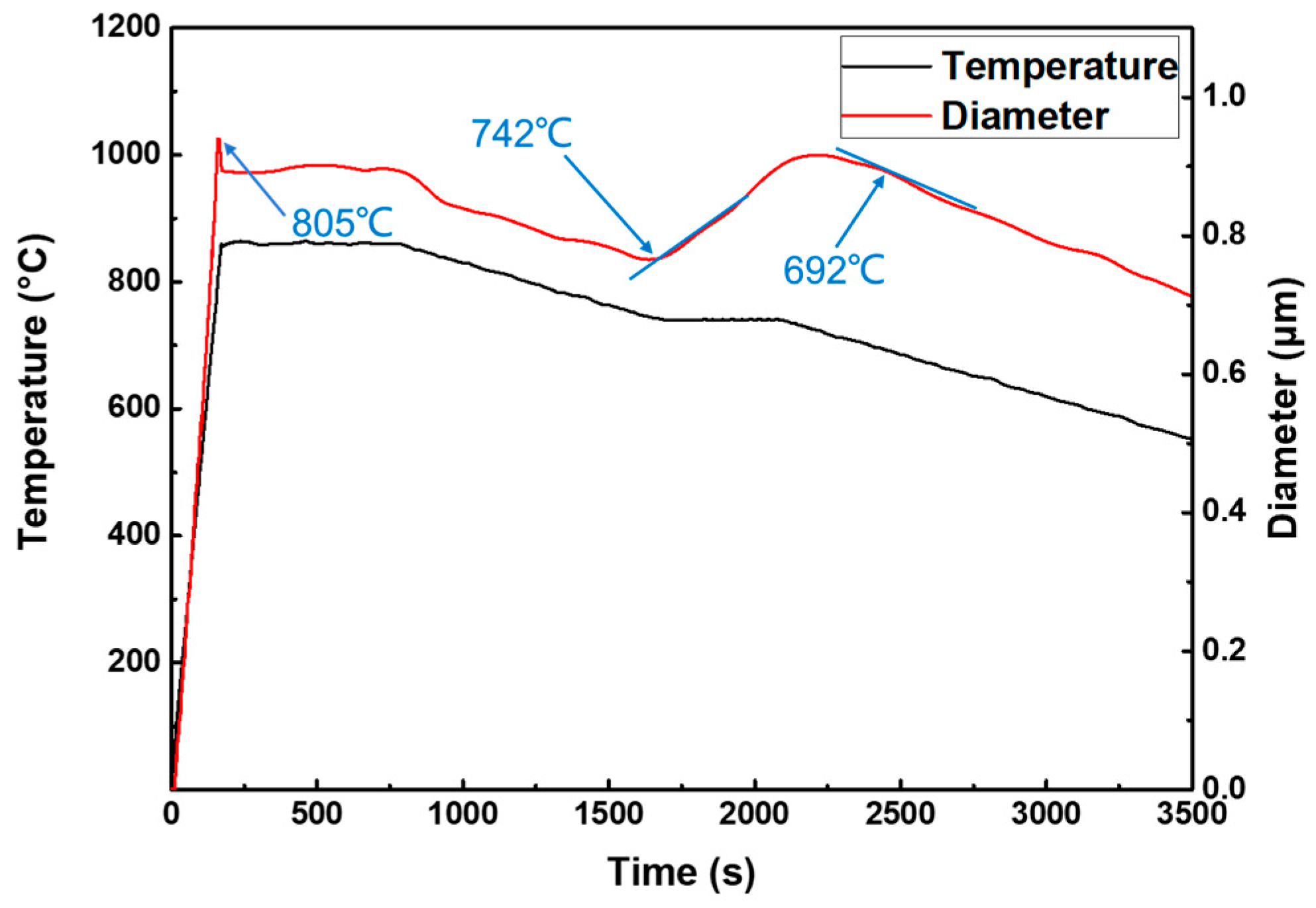
  • The microstructure evolution during the rapid spheroidization process is summarized. It is found that the ferrite first transforms into austenite and the carbides partially dissolve during the partial austenitization. As the temperature falls into the temperature range of DET, the fresh carbides precipitate and adhere to the undissolved carbides to grow globularly. Meanwhile, the austenite begins to transform into ferrite. The carbides could be broken up and the ferrite is refined by the applied WD. As a result, the carbide spheroidization process is accelerated. Additionally, the WD can effectively lead to the uniform distribution of primary carbides;
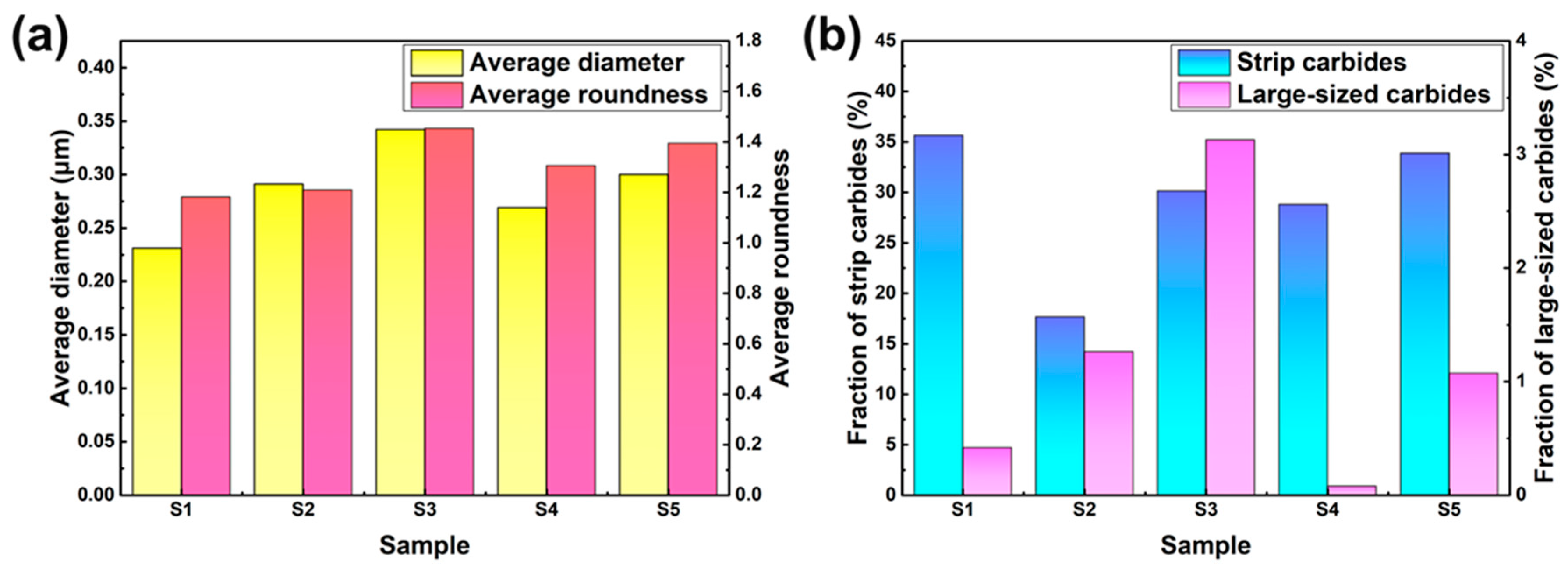
  • With the increase in WD temperature, the deformation resistance, as well as the hardness decreases, which could be associated with the decreased dislocation density and better spheroidization effect. In addition, there is an optimal WD temperature (760 °C) to maximize the degree of DET. The sample deformed at 760 °C exhibits the finest size and best roundness of carbides, thereby showing the lowest hardness;
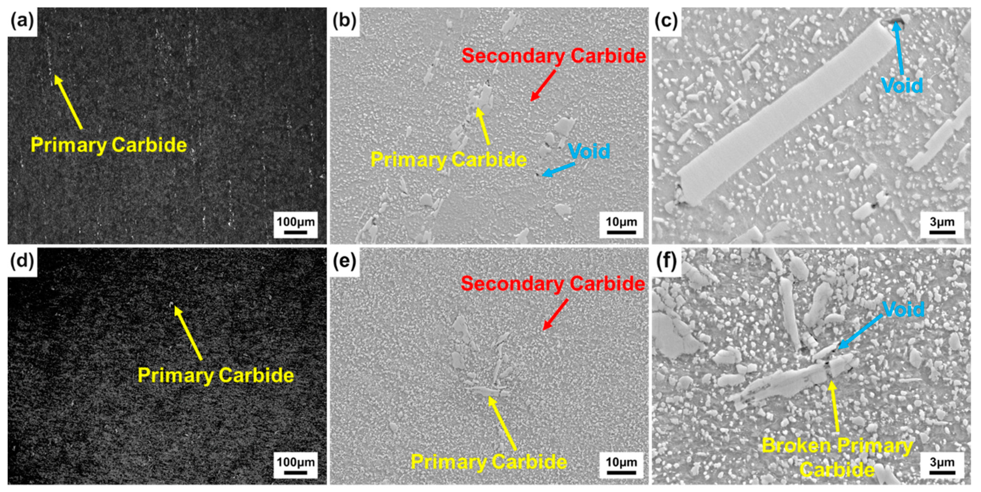
  • Compared with the SA-CD process, the number of large-sized carbides significantly decreases for the proposed rapid SA (DET-WD process). The local stress and dislocation density are also lower than that of SA-CD samples. Compared with the HD-SA process, the proportion of spherical carbides is increased by 5.7% and the roundness is better. The excellent roundness of spheroidized carbides (1.333) and the lowest hardness (217 HV) are achieved in the DET-WD samples for the final cutting of bearing products. This work provides a highly efficient routine to simultaneously realize the SA and shape forming, which is of great engineering significance for the manufacturing of bearings.

Author Contributions

Conceptualization, D.Q. and F.W.; methodology, D.Q.; software, B.C.; validation, D.Q., B.C., and F.W.; formal analysis, B.C.; investigation, B.C.; resources, D.Q.; data curation, D.Q.; writing—original draft preparation, B.C. and L.W.; writing—review and editing, D.Q. and F.W.; visualization, D.Q.; supervision, D.Q.; project administration, D.Q.; funding acquisition, D.Q. All authors have read and agreed to the published version of the manuscript.

Funding

This research was funded by the National Key R&D Program of China (No. 2020YFA0714900), National Natural Science Foundation of China (No. 51875426), 111 Project (B17034) and Innovative Research Team Development Program of Ministry of Education of China (No. IRT_17R83).

Data Availability Statement

The raw/processed data required to reproduce these findings cannot be shared at this time as the data also forms part of an ongoing study.

Acknowledgments

The work was supported by the National Key R&D Program of China (No.2020YFA0714900), National Natural Science Foundation of China (No. 51875426), 111 Project (B17034) and Innovative Research Team Development Program of Ministry of Education of China (No. IRT_17R83).

Conflicts of Interest

The authors declare no conflict of interest.

Abbreviations

SASpheroidizing annealing
SRAStress relief annealing
DETDivorced eutectoid transformation
ETEutectoid transformation
WDWarm deformation
CDCold deformation
HDHot deformation
DET-WDWD process that combines with SA process
SA-CDCD process that combines with SA process
HD-SAHD process that combines with SA process

References

  1. Bhadeshia, H. Steels for bearings. Prog. Mater. Sci. 2012, 57, 268–435. [Google Scholar] [CrossRef]
  2. Dodd, A.; Kinder, J.; Torp, B.; Nielsen, B.R.; Rangel, C.M.; da Svila, M.F. The effect of ion implantation on the fatigue life and corrosion resistance of M50 steel bearings. Surf. Coat. Technol. 1995, 74, 754–759. [Google Scholar] [CrossRef]
  3. Hua, L.; Deng, J.D. Recent development of ring rolling theory and technique. Int. J. Mater. Product. Technol. 2017, 54, 273–276. [Google Scholar] [CrossRef]
  4. Peng, N.Q.; Tang, G.B.; Yao, J.; Liu, Z.D. Hot Deformation Behavior of GCr15 Steel. J. Iron Steel Res. Int. 2013, 20, 50–56. [Google Scholar] [CrossRef]
  5. Wang, F.; Qian, D.S.; Hua, L.; Lu, X.H. The effect of prior cold rolling on the carbide dissolution, precipitation and dry wear behaviors of M50 bearing steel. Tribol. Int. 2018, 132, 253–264. [Google Scholar] [CrossRef]
  6. Jiang, H.; Song, Y.; Wu, Y.; Shan, D.; Zong, Y. Macrostructure, microstructure and mechanical properties evolution during 8Cr4Mo4V steel roller bearing inner ring forging process. Mater. Sci. Eng. A 2020, 798, 140196. [Google Scholar] [CrossRef]
  7. Li, Z.X.; Li, C.S.; Ren, J.Y.; Li, B.Z.; Zhang, J.; Ma, Y.Q. Effect of cold deformation on the microstructure and impact toughness during the austenitising process of 1.0C-1.5Cr bearing steel. Mater. Sci. Eng. A 2016, 674, 262–269. [Google Scholar] [CrossRef]
  8. Okitsu, Y.; Takata, N.; Tsuji, Y.N. A new route to fabricate ultrafine-grained structures in carbon steels without severe plastic deformation. Scr. Mater. 2009, 60, 76–79. [Google Scholar] [CrossRef]
  9. Young, C.H.; Bhadeshia, H.K.D.H. Strength of mixtures of bainite and martensite. Mater. Sci. Technol. 1994, 10, 209–214. [Google Scholar] [CrossRef]
  10. Ankit, K.; Mukherjee, R.; Nestler, B. Deviations from cooperative growth mode during eutectoid transformation: Mechanisms of polycrystalline eutectoid evolution in Fe–C steels. Acta Mater. 2015, 97, 316–324. [Google Scholar] [CrossRef]
  11. Oyama, T.; Sherby, O.D.; Wadsworth, J.; Walser, B. Application of the divorced eutectoid transformation to the development of fine-grained, spheroidized structures in ultrahigh carbon steels. Scr. Metall. 1984, 18, 799–804. [Google Scholar] [CrossRef]
  12. Huo, X.D.; Guo, L.; He, K.N.; Huang, R. Effect of Spheroidizing Annealing Time on Microstructure and Hardness of GCr15 Bearing Steel. Adv. Mater. Res. 2012, 581–582, 928–931. [Google Scholar] [CrossRef]
  13. Pandit, S.A.; Bhadeshia, K.D.H.H. Divorced pearlite in steels. Proc. R. Soc. A Math. Phys. Eng. Sci. 2012, 468, 2767–2778. [Google Scholar] [CrossRef] [Green Version]
  14. Chen, Q.W.; Zhu, G.H.; Cao, S.M.; Zhao, A.M. Quick spherodizing in GCr15 steel by mechanism of divorced eutectoid. Adv. Mate. Res. 2011, 295–297, 515–519. [Google Scholar] [CrossRef]
  15. Xing, C.L.; Peng, Y.; Xing, J.K.; Zang, Y. Effects of warm rolling and spheroidizing annealing processes on microstructure and mechanical properties of 45 steel. Heat Treat. Met. 2015, 40, 94–98. [Google Scholar]
  16. Huang, J.X.; Wang, J.T.; Zhang, Z. Equal Channel Angular Processing in a Pearlitic structured steel. Chin. J. Mater. Res. 2005, 2, 200–206. [Google Scholar]
  17. Qian, D.S.; Yang, J.; Mao, H.J.; Hua, L. Experiment study on warm ring rolling of 52100 bearing steel coupling microstructure spheroidisation. Proc. Eng. 2017, 207, 1224–1229. [Google Scholar] [CrossRef]
  18. Qian, D.S.; Wang, H.L.; Pan, L.B.; Wang, F.; Lu, X.H. Obtaining ultrafine spheroidized carbides by combining warm deformation with divorced eutectoid transformation in GCr15 bearing steel. Mater. Res. Express 2020, 7, 046505. [Google Scholar] [CrossRef]
  19. Han, D.X.; Du, L.X.; Dong, Y.; Misra, R.D.K. The Impact of Deformation Conditions on Divorced Eutectoid Transformation in Bearing Steels. Steel Res. Int. 2019, 90, 1800384. [Google Scholar] [CrossRef]
  20. Han, D.X.; Du, L.X.; Zhang, B.; Misra, R.D.K. Effect of deformation on deformation-induced carbides and spheroidization in bearing steel. J. Mater. Sci. 2019, 54, 2612–2627. [Google Scholar] [CrossRef]
  21. Yin, Z.X.; Xu, Y.; Liang, J.Q.; Chen, J.L.; Li, J.F. Divorced eutectoid transformation in GCr15 steel. Heat Treat. Met. 2019, 44, 11–16. [Google Scholar]
  22. Williamson, G.K.; Hall, W.H. X-Ray line broadening from field aluminium and wofram. Acta Metall. 1953, 1, 22–31. [Google Scholar] [CrossRef]
  23. Abdollah-Zadeh, A.; Eghbali, B. Mechanism of ferrite grain refinement during warm deformation of a low carbon Nb-microalloyed steel. Mater. Sci. Eng. A 2007, 457, 219–225. [Google Scholar] [CrossRef]
  24. Tiryakioglu, M.; Campbell, J.; Staley, J.T. Hardness-Strength Relationships in Cast Al-Si-Mg Alloys. Mater. Sci. Forum 2000, 331, 295–300. [Google Scholar] [CrossRef]
Figure 1. (a) Schematic illustration of the thermal expansion test; (b) The measured thermal expansion curve during heating and cooling.
Metals 12 00359 g001
Figure 2. Microstructure of the samples subjected to pearlite transformation at different holding temperatures.
Metals 12 00359 g002
Figure 3. The hardness of the samples subjected to pearlite transformation at different holding temperatures.
Metals 12 00359 g003
Figure 4. Schematic illustration of different deformation with SA processes: (a) DET-WD process; (b) SA-CD process; (c) HD-SA process.
Metals 12 00359 g004
Figure 5. Microstructure evolution during the DET-WD process: (a) S1; (b) S2; (c) S3; (d) S4; (e) S5.
Metals 12 00359 g005
Figure 6. Statistical result of carbides during the DET-WD process: (a) average diameter and average roundness; (b) the proportion of strip carbides and large-sized carbides.
Metals 12 00359 g006
Figure 7. The XRD patterns of carbide powder in the initial material and S1.
Metals 12 00359 g007
Figure 8. OM and SEM micrographs of primary carbides in the DET-WD process: (ac) initial material; (df) S5.
Metals 12 00359 g008
Figure 9. Thermal expansion curve of the DET process.
Metals 12 00359 g009
Figure 10. SEM micrographs of the samples at different deformation temperatures in the DET-WD process: (a) 720 °C; (b) 740 °C; (c) 760 °C.
Metals 12 00359 g010
Figure 11. Statistical result of carbides at different deformation temperatures in the DET-WD process: (a) average diameter and average roundness; (b) the proportion of strip carbides and large-sized carbides.
Metals 12 00359 g011
Figure 12. Stress–strain curves at different deformation temperatures in the DET-WD process.
Metals 12 00359 g012
Figure 13. SEM micrographs of the samples subjected to (a) SA-CD, (b) HD-SA, and (c) DET-WD processes.
Metals 12 00359 g013
Figure 14. Statistical result of carbides of the samples subjected to SA-CD, HD-SA, and DET-WD processes: (a) average diameter and average roundness; (b) the proportion of strip carbides and large-sized carbides.
Metals 12 00359 g014
Figure 15. XRD diffraction patterns of the samples subjected to SA-CD, HD-SA, and DET-WD processes.
Metals 12 00359 g015
Figure 16. EBSD inverse pole figure maps of the samples subjected to (a) SA-CD, (b) HD-SA, and (c) DET-WD processes.
Metals 12 00359 g016
Figure 17. ϕ2 = 45° in Euler space represent the orientation distribution functions maps: (a) SA-CD sample, (b) HD-SA sample, (c) DET-WD sample, (d) nominal position of basic texture components.
Metals 12 00359 g017
Figure 18. Distribution of grain boundary and misorientation of the samples subjected to (a) SA-CD, (b) HD-SA, and (c) DET-WD processes.
Metals 12 00359 g018
Figure 19. Kernel average misorientation maps of the samples subjected to (a) SA-CD, (b) HD-SA, and (c) DET-WD processes.
Metals 12 00359 g019
Table 1. Chemical composition of M50 bearing steel (wt. %).
CCrMoVMnSiWFe
0.804.064.21.080.220.250.16Bal.
Publisher’s Note: MDPI stays neutral with regard to jurisdictional claims in published maps and institutional affiliations.

