
Enhanced Wear Resistance of the Ultrastrong Ultrasonic Shot-Peened M50 Bearing Steel with Gradient Nanograins

 , ,
, ,
Abstract
:1. Introduction
2. Materials and Methods
2.1. Materials
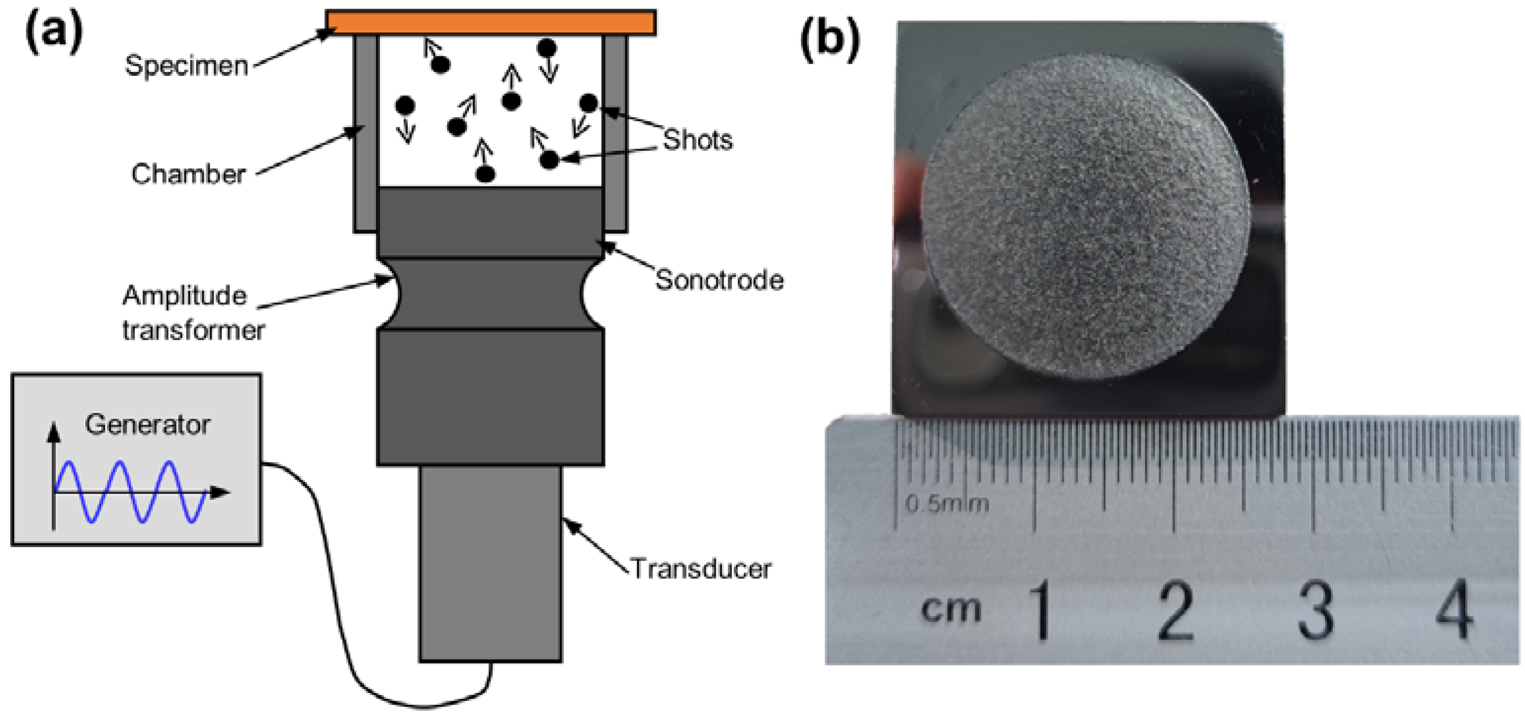
2.2. USP Treatment
2.3. Materials Characterizations
2.4. Wear Tests
3. Results
3.1. Surface Roughness
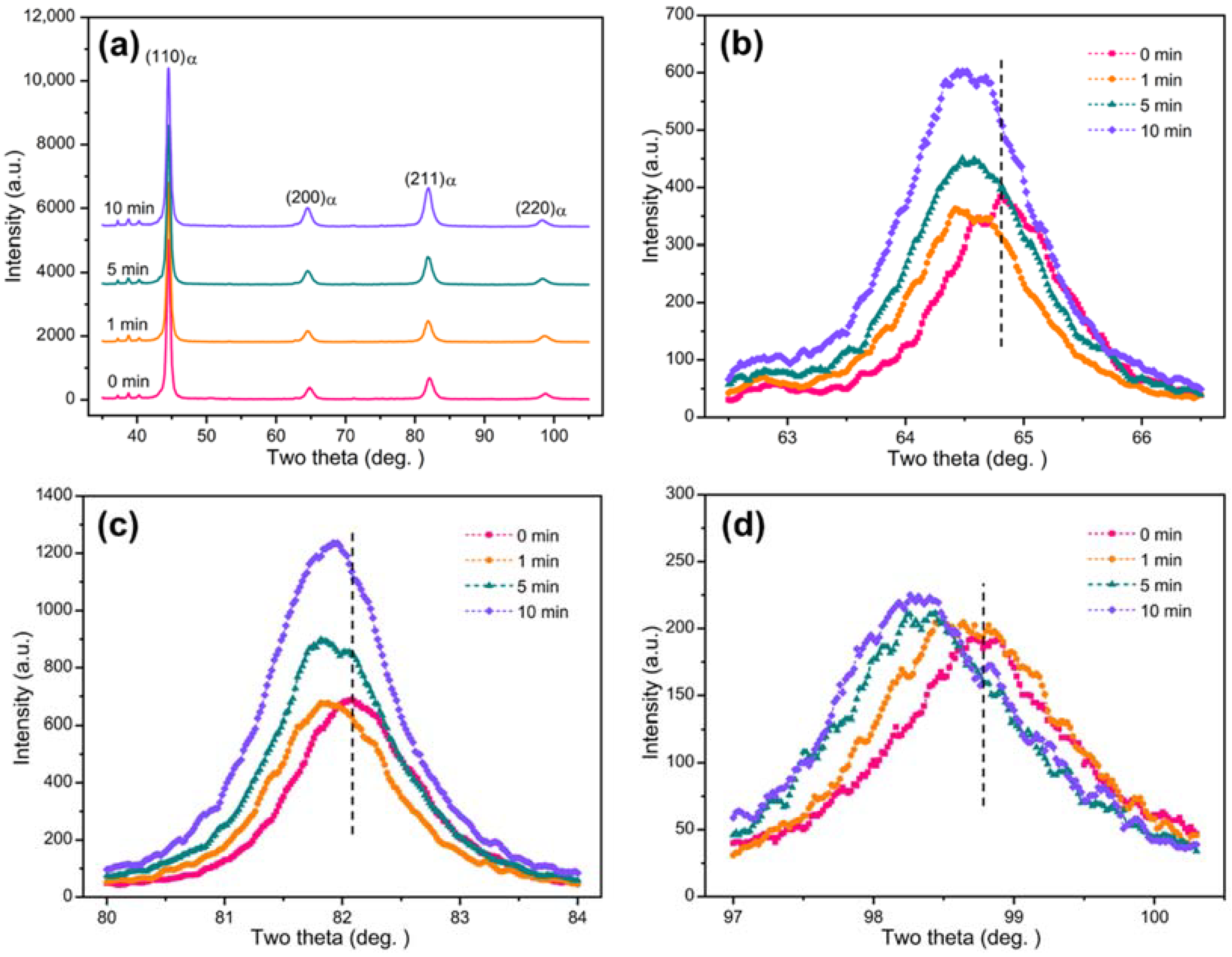
3.2. X-ray Diffractograms
3.3. Gradient Nanograined Structure
3.4. Microhardness and Residual Stress
3.5. Wear Behavior
4. Discussion
4.1. Microstructure Refinement Mechanism
4.2. Hardening Mechanism
4.3. Wear Mechanism
5. Conclusions
- (a)
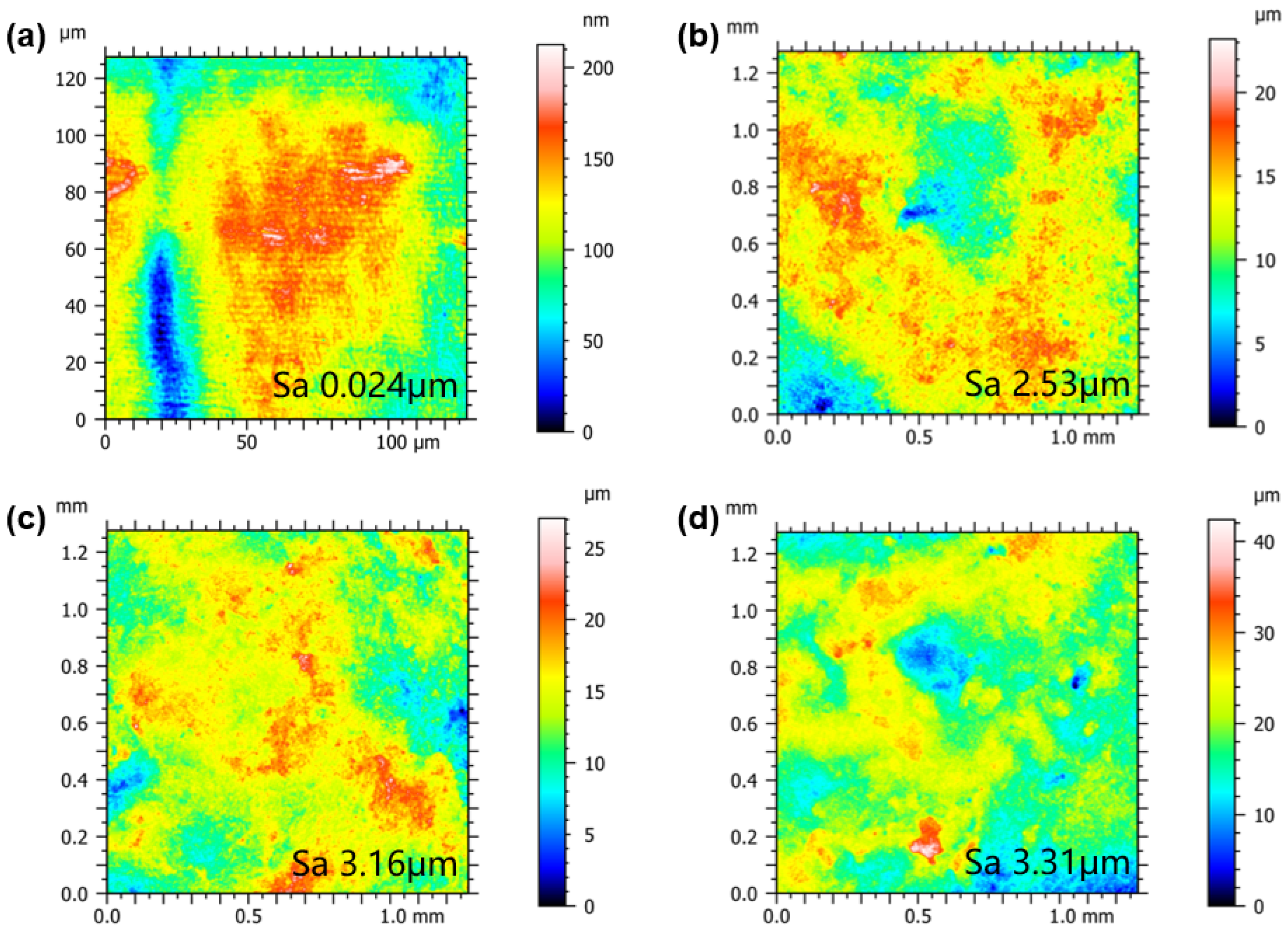
- USP treatment can increase the surface roughness of M50 steel, and the surface roughness increases with the duration of USP treatment (from Sa 2.53 μm at 1 min to Sa 3.31 μm at 10 min).
- (b)
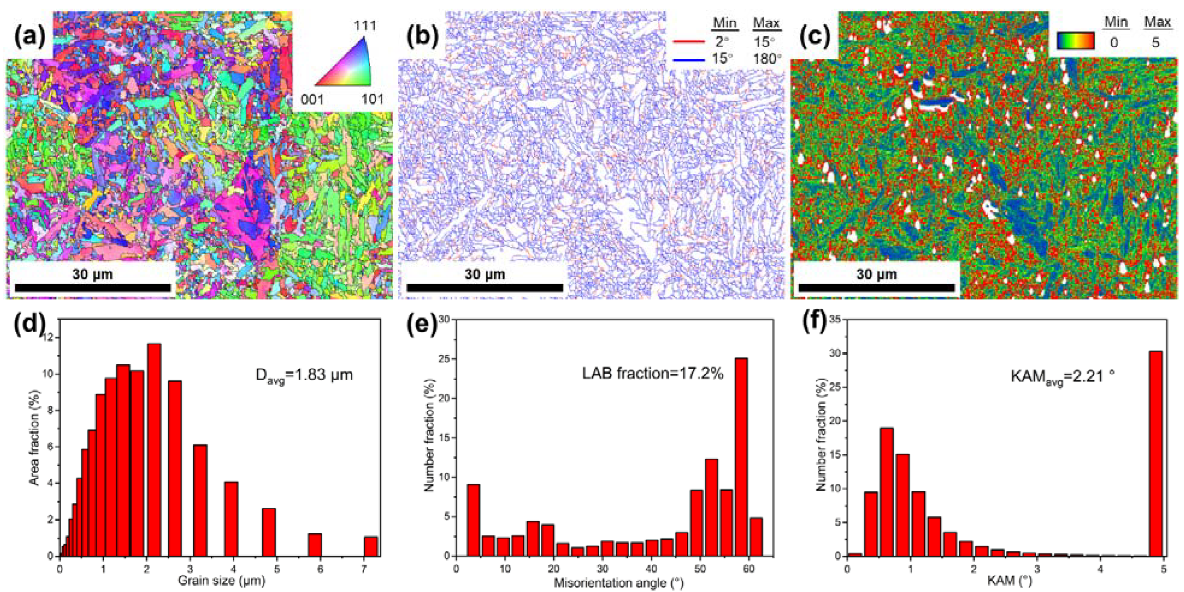
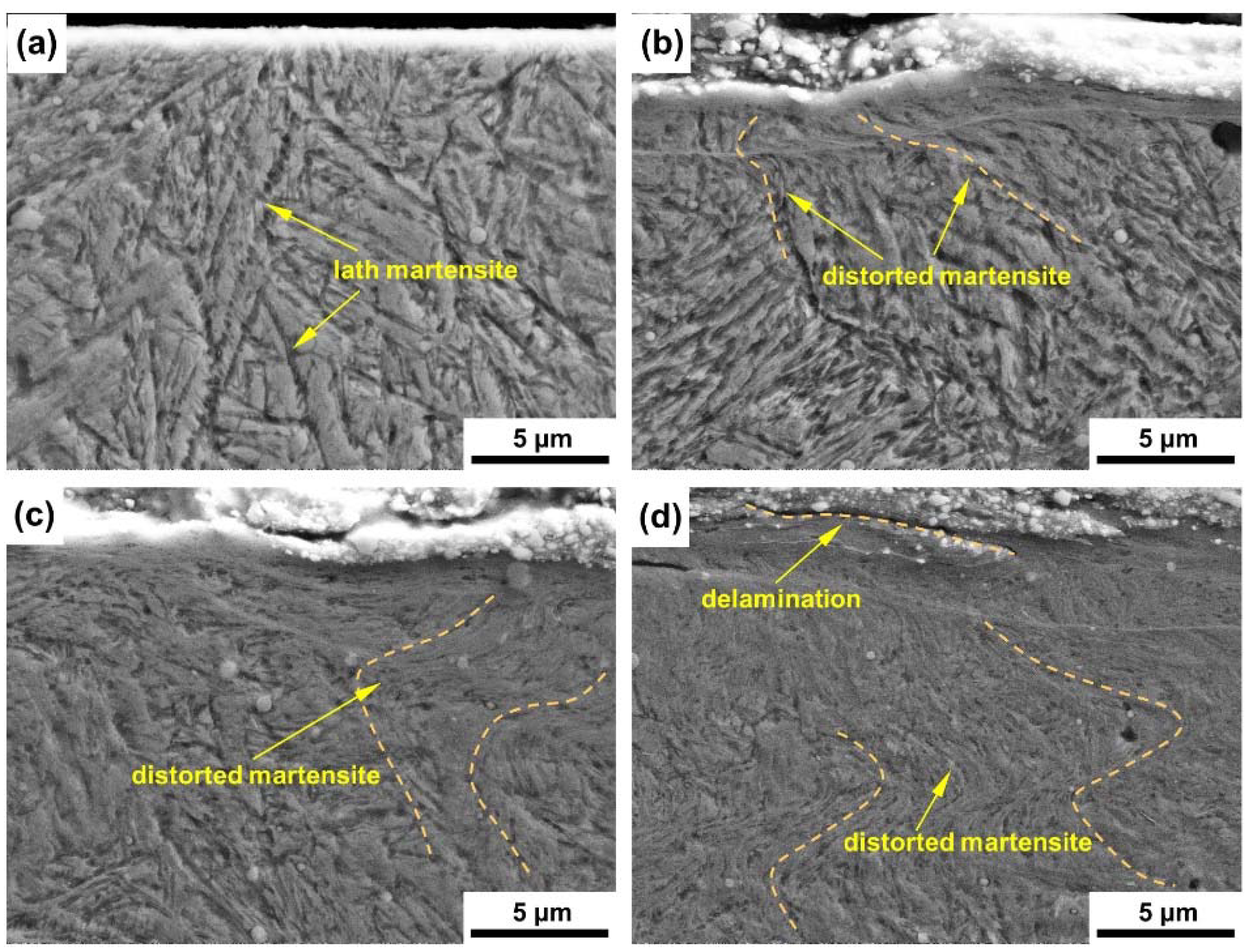
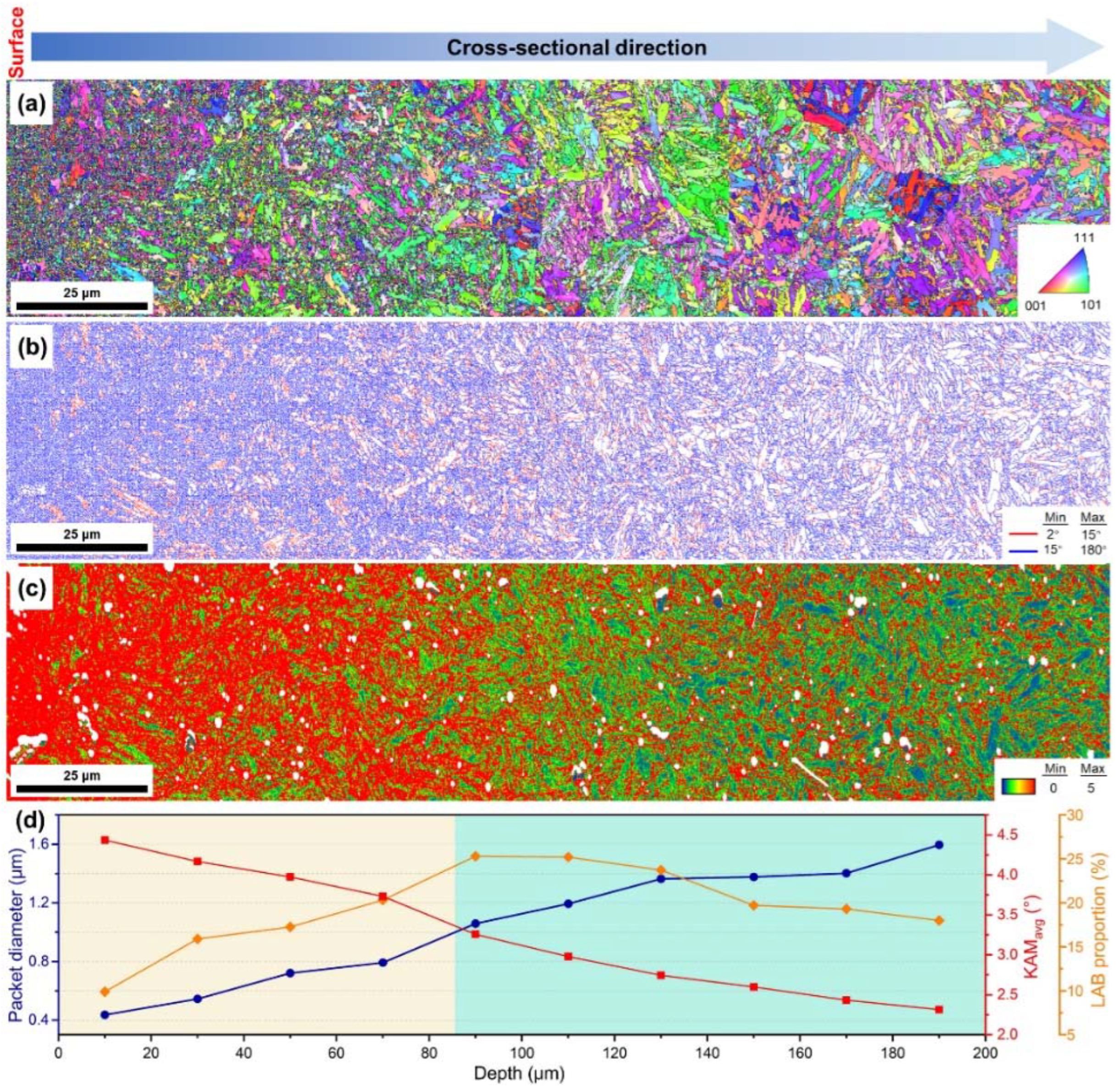
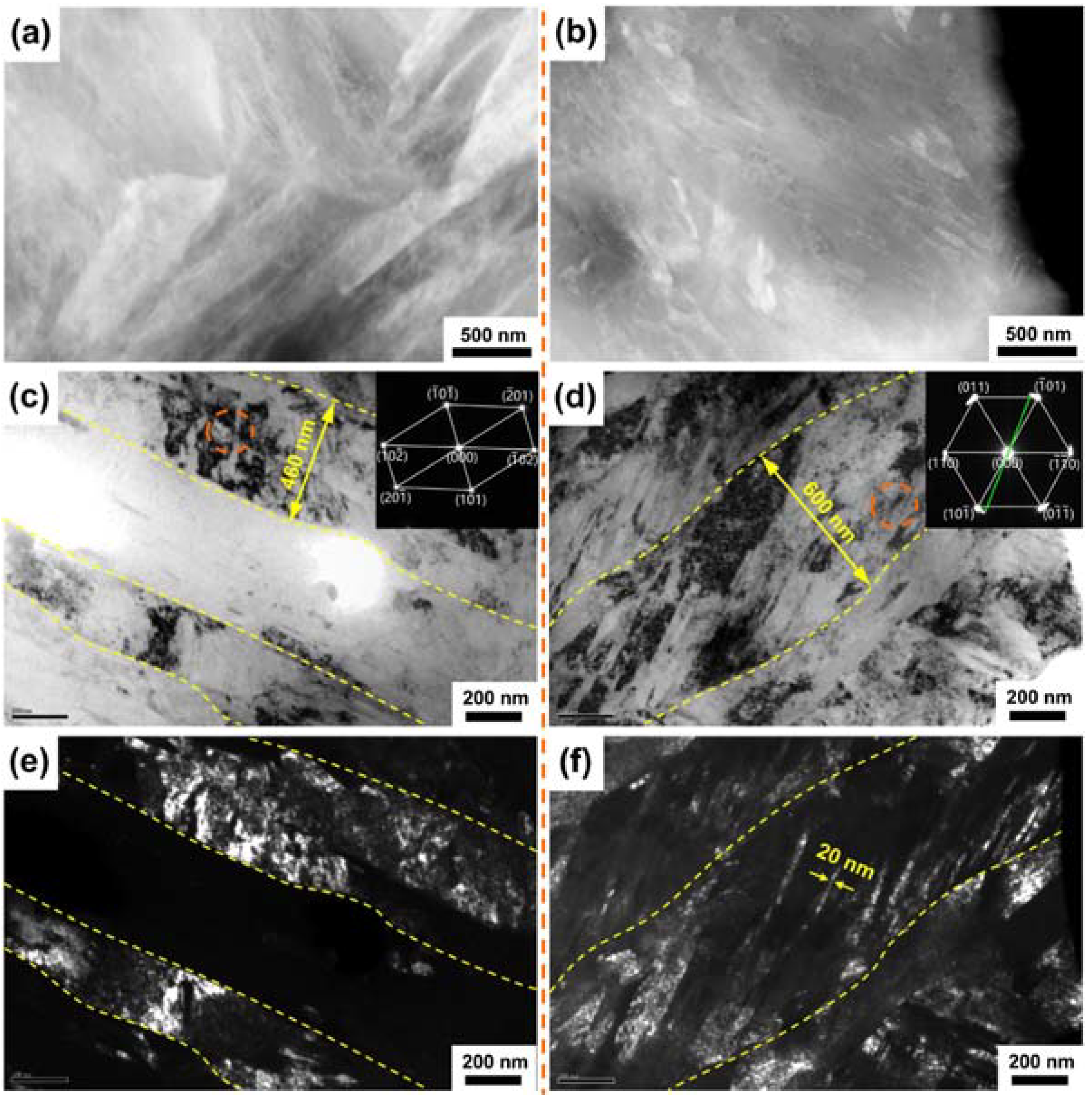
- The dislocation density of the M50 steel has been greatly increased after USP treatment. A gradient nanograined surface layer with a thickness of more than 200 μm was fabricated and the thickness of the lath martensite has refined down to 20~600 nm. The high KAM value proves the presence of high dislocation density in the near-surface layer in the USP-treated M50 steel, and the dislocation density gradually decreases with increasing depth.
- (c)
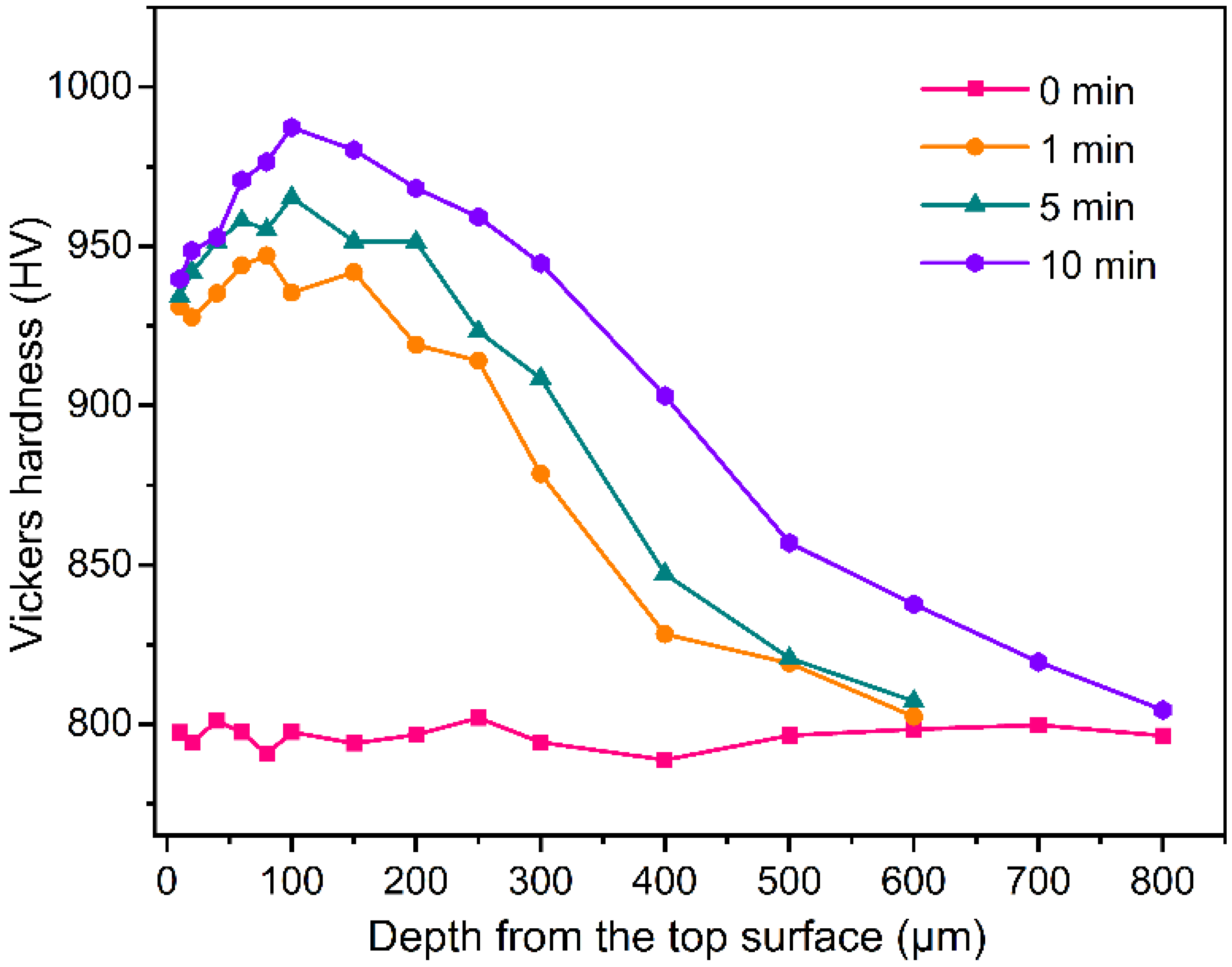
- The surface residual compressive stress is increased from 427.0 MPa to 1202.8 MPa. Additionally, the maximum hardness of the USP-treated M50 bearing steel is increased by 24% (from 795 HV to 987 HV) at a depth of around 100 μm. Beyond 100 μm, the hardness of USP treated M50 steel decreases with increasing depth. The trend follows that of the LABs proportion along the depth direction.
- (d)
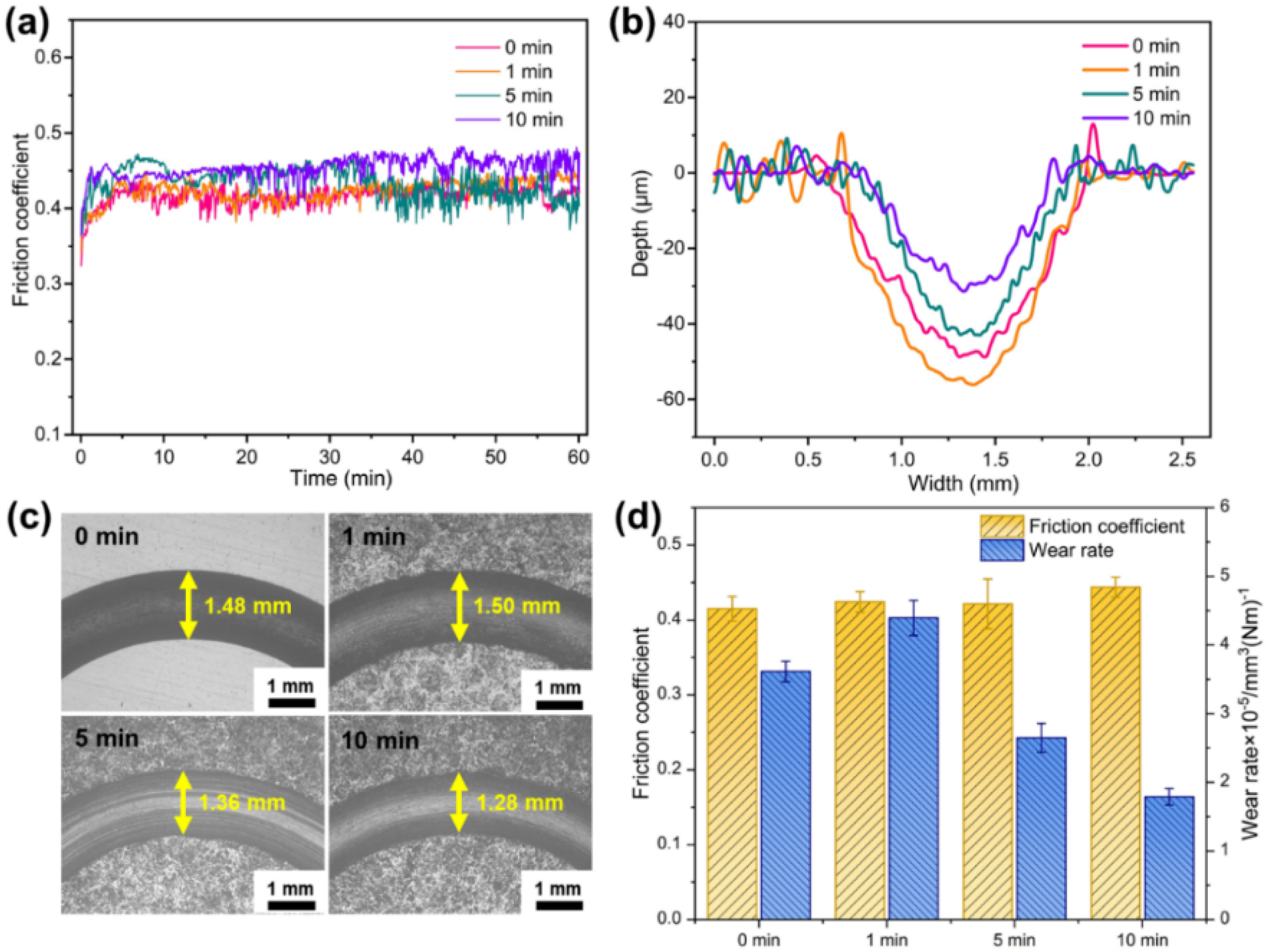
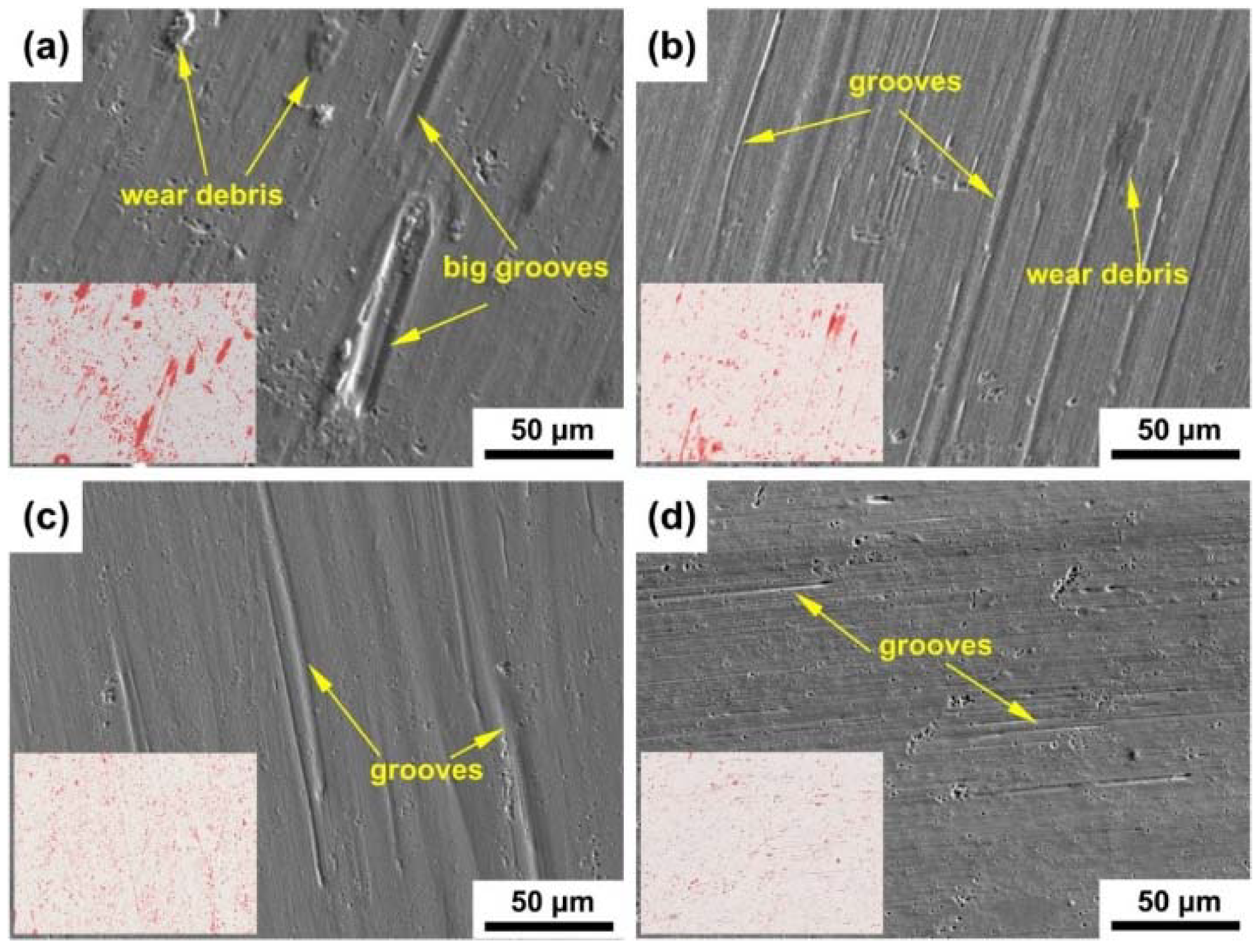
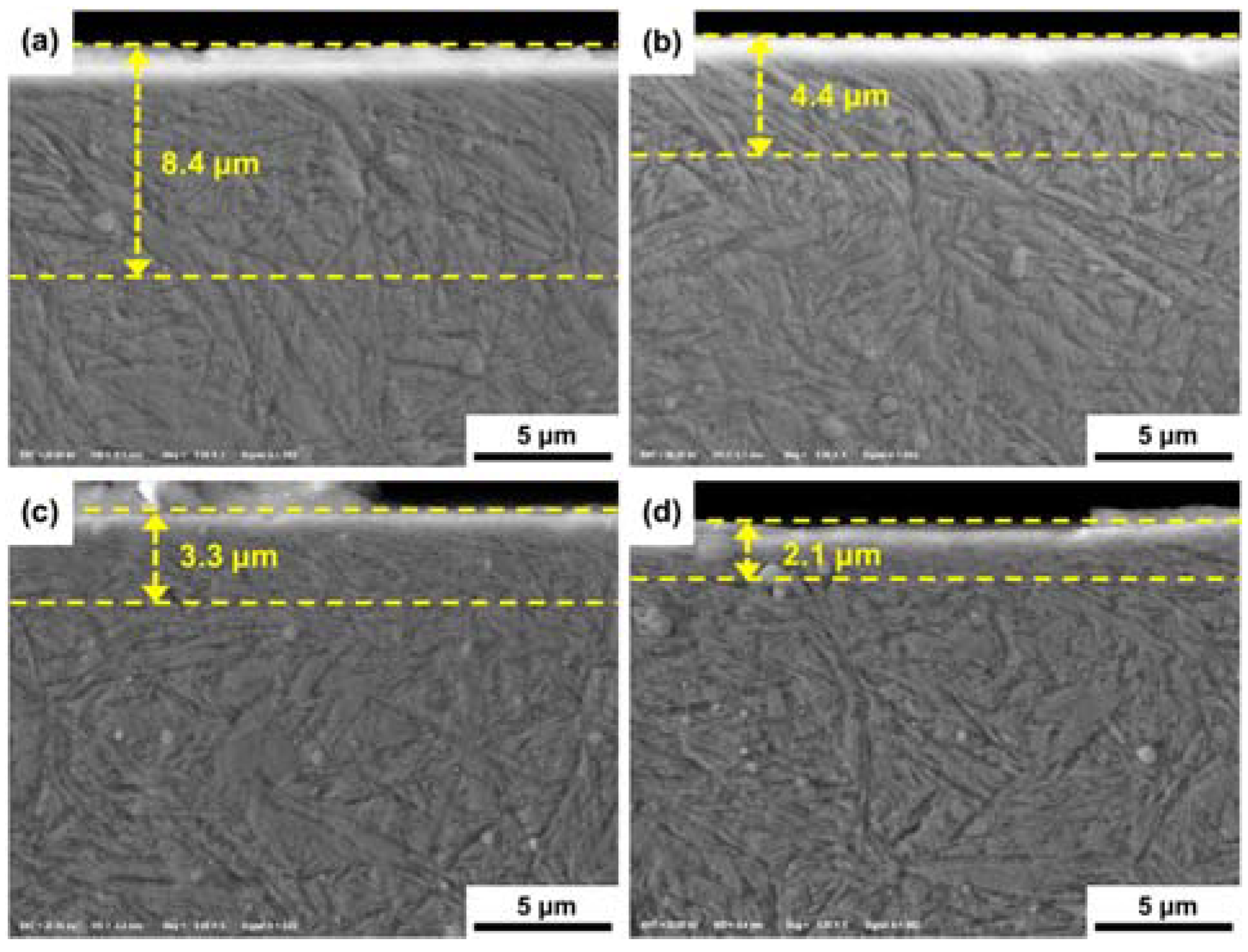
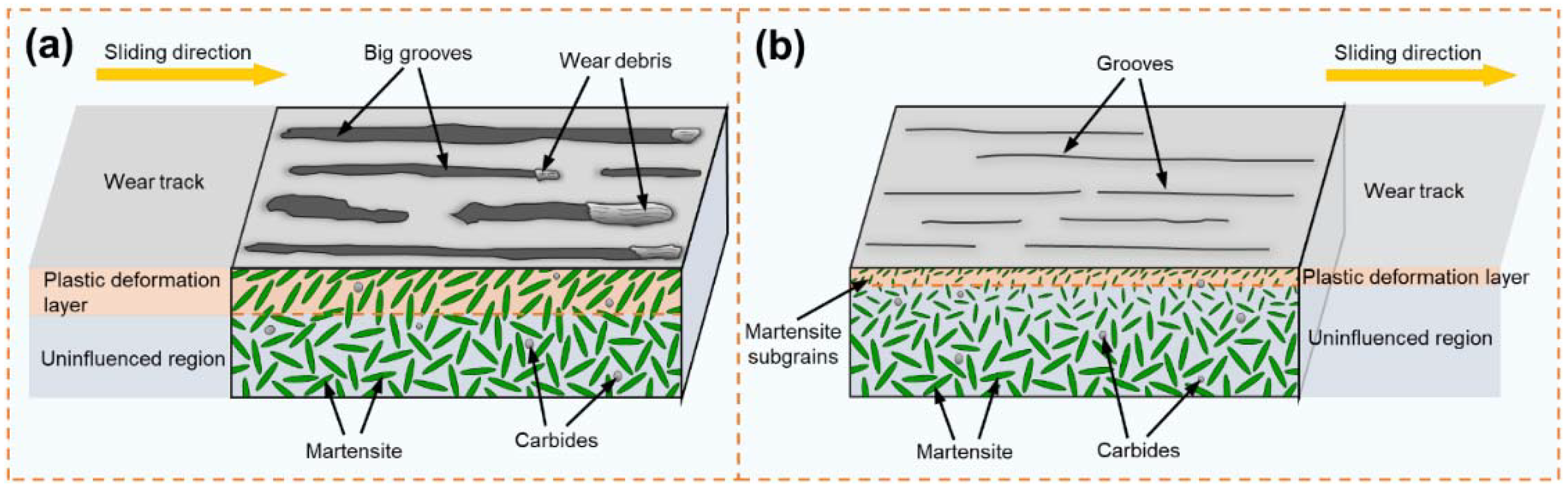
- The wear rate of the USP-treated M50 steel is reduced by 50.4% under sliding conditions compared to that of the untreated M50 steel, due to the ultrastrong surface layer with gradient nanograin. As the duration of USP treatment increases, the wear mechanism of the gradient nanostructured M50 bearing steel changes from oxidative wear and severe plowing wear to mild plowing wear, and the thickness of the plastic deformation layer generated during the friction process is reduced.
Author Contributions
Funding
Conflicts of Interest
Nomenclature
| HABs | High angle boundaries |
| IPF | Inverse pole figure |
| KAM | Kernel average misorientation |
| LABs | Low angle boundaries |
| POD | Pin-on-disk |
| QT | Quenching and tempering |
| SP | Shot peening |
| USP | Ultrasonic shot peening |
References
- Zaretsky, E.V. Rolling bearing steels–a technical and historical perspective. Mater. Sci. Technol. 2012, 28, 58–69. [Google Scholar] [CrossRef] [Green Version]
- Bhadeshia, H.K.D.H. Steels for bearings. Prog. Mater. Sci. 2012, 57, 268–435. [Google Scholar] [CrossRef]
- Babutskyi, A.; Chrysanthou, A.; Zhao, C. Effect of pulsed magnetic field pre-treatment of AISI 52100 steel on the coefficient of sliding friction and wear in pin-on-disk tests. Friction 2014, 2, 310–316. [Google Scholar] [CrossRef] [Green Version]
- Kovacı, H.; Hacısalihoğlu, İ.; Yetim, A.F.; Çelik, A. Effects of shot peening pre-treatment and plasma nitriding parameters on the structural, mechanical and tribological properties of AISI 4140 low-alloy steel. Surf. Coat. Technol. 2019, 358, 256–265. [Google Scholar] [CrossRef]
- Yan, M.F.; Zhang, C.S.; Sun, Z. Study on depth-related microstructure and wear property of rare earth nitrocarburized layer of M50NiL steel. Appl. Surf. Sci. 2014, 289, 370–377. [Google Scholar] [CrossRef]
- Yan, M.F.; Chen, B.F.; Li, B. Microstructure and mechanical properties from an attractive combination of plasma nitriding and secondary hardening of M50 steel. Appl. Surf. Sci. 2018, 455, 1–7. [Google Scholar] [CrossRef]
- Soady, K.A.; Mellor, B.G.; West, G.D.; Harrison, G.; Morris, A.; Reed, P.A.S. Evaluating surface deformation and near surface strain hardening resulting from shot peening a tempered martensitic steel and application to low cycle fatigue. Int. J. Fatigue 2013, 54, 106–117. [Google Scholar] [CrossRef]
- Gopi, R.; Saravanan, I.; Devaraju, A.; Loganathan, G.B. Investigation of shot peening process on stainless steel and its effects for tribological applications. Mater. Today Proc. 2020, 22, 580–584. [Google Scholar] [CrossRef]
- Shen, Y.; Moghadam, S.M.; Sadeghi, F.; Paulson, K.; Trice, R.W. Effect of retained austenite–Compressive residual stresses on rolling contact fatigue life of carburized AISI 8620 steel. Int. J. Fatigue 2015, 75, 135–144. [Google Scholar] [CrossRef]
- Macek, W. Fracture Areas Quantitative Investigating of Bending-Torsion Fatigued Low-Alloy High-Strength Steel. Metals 2021, 11, 1620. [Google Scholar] [CrossRef]
- Masoudi Nejad, R.; Berto, F. Fatigue fracture and fatigue life assessment of railway wheel using non-linear model for fatigue crack growth. Int. J. Fatigue 2021, 153, 106516. [Google Scholar] [CrossRef]
- Polonsky, I.A.; Chang, T.P.; Keer, L.M.; Sproul, W.D. An analysis of the effect of hard coatings on near-surface rolling contact fatigue initiation induced by surface roughness. Wear 1997, 208, 204–219. [Google Scholar] [CrossRef]
- Otsuka, A.; Fujii, Y.; Maeda, K. A new testing method to obtain mode 2 fatigue crack growth characteristics of hard materials. Fatigue Fract. Eng. Mater. Struct. 2004, 27, 203–212. [Google Scholar] [CrossRef]
- Wang, F.; Qian, D.; Hua, L.; Lu, X. The effect of prior cold rolling on the carbide dissolution, precipitation and dry wear behaviors of M50 bearing steel. Tribol. Int. 2019, 132, 253–264. [Google Scholar] [CrossRef]
- Yasnii, P.V.; Marushchak, P.O.; Hlad’o, V.B.; Nikiforov, Y.M.; Kovalyuk, B.P. Influence of laser shock-wave treatment on the impact toughness of heat-resistant steels. Mater. Sci. 2010, 46, 425–429. [Google Scholar] [CrossRef]
- Yin, M.-G.; Cai, Z.-B.; Li, Z.-Y.; Zhou, Z.-R.; Wang, W.-J.; He, W.-F. Improving impact wear resistance of Ti-6Al-4V alloy treated by laser shock peening. Trans. Nonferrous Met. Soc. China 2019, 29, 1439–1448. [Google Scholar] [CrossRef]
- Yin, F.; Hu, S.; Xu, R.; Xiang, S.; Hua, L.; Cheng, G.J. Ultrastrong medium entropy alloy with simultaneous strength-ductility improvement via heterogeneous nanocrystalline structures. Mater. Sci. Eng. A 2021, 823, 141631. [Google Scholar] [CrossRef]
- Yin, F.; Hu, S.; Xu, R.; Han, X.; Qian, D.; Wei, W.; Hua, L.; Zhao, K. Strain rate sensitivity of the ultrastrong gradient nanocrystalline 316L stainless steel and its rate-dependent modeling at nanoscale. Int. J. Plast. 2020, 129, 102696. [Google Scholar] [CrossRef]
- Yin, F.; Rakita, M.; Hu, S.; Han, Q. Overview of ultrasonic shot peening. Surf. Eng. 2017, 33, 651–666. [Google Scholar] [CrossRef]
- Yin, F.; Hua, L.; Wang, X.; Rakita, M.; Han, Q. Numerical modelling and experimental approach for surface morphology evaluation during ultrasonic shot peening. Comput. Mater. Sci. 2014, 92, 28–35. [Google Scholar] [CrossRef]
- Chen, H.; Guan, Y.; Zhu, L.; Li, Y.; Zhai, J.; Lin, J. Effects of ultrasonic shot peening process parameters on nanocrystalline and mechanical properties of pure copper surface. Mater. Chem. Phys. 2021, 259, 124025. [Google Scholar] [CrossRef]
- Wu, X.; Tao, N.; Hong, Y.; Xu, B.; Lu, J.; Lu, K. Microstructure and evolution of mechanically-induced ultrafine grain in surface layer of AL-alloy subjected to USSP. Acta Mater. 2002, 50, 2075–2084. [Google Scholar] [CrossRef]
- Yin, F.; Cheng, G.J.; Xu, R.; Zhao, K.; Li, Q.; Jian, J.; Hu, S.; Sun, S.; An, L.; Han, Q. Ultrastrong nanocrystalline stainless steel and its Hall-Petch relationship in the nanoscale. Scr. Mater. 2018, 155, 26–31. [Google Scholar] [CrossRef]
- Bagherifard, S.; Slawik, S.; Fernández-Pariente, I.; Pauly, C.; Mücklich, F.; Guagliano, M. Nanoscale surface modification of AISI 316L stainless steel by severe shot peening. Mater. Des. 2016, 102, 68–77. [Google Scholar] [CrossRef]
- Yin, F.; Liu, Y.; Xu, R.; Zhao, K.; Partin, A.; Han, Q. Nanograined surface fabricated on the pure copper by ultrasonic shot peening and an energy-density based criterion for peening intensity quantification. J. Manuf. Process. 2018, 32, 656–663. [Google Scholar] [CrossRef]
- Karimbaev, R.; Pyun, Y.-S.; Maleki, E.; Unal, O.; Amanov, A. An improvement in fatigue behavior of AISI 4340 steel by shot peening and ultrasonic nanocrystal surface modification. Mater. Sci. Eng. A 2020, 791, 139752. [Google Scholar] [CrossRef]
- Sun, Q.; Han, Q.; Xu, R.; Zhao, K.; Li, J. Localized corrosion behaviour of AA7150 after ultrasonic shot peening: Corrosion depth vs. impact energy. Corros. Sci. 2018, 130, 218–230. [Google Scholar] [CrossRef]
- Zou, Y.; Li, J.; Liu, X.; He, T.; Lu, J.; Li, D.; Li, Y. Effect of multiple ultrasonic nanocrystal surface modification on surface integrity and wear property of DZ2 axle steel. Surf. Coat. Technol. 2021, 412, 127012. [Google Scholar] [CrossRef]
- Archard, J.F. Contact and rubbing of flat surfaces. J. Appl. Phys. 1953, 24, 981–988. [Google Scholar] [CrossRef]
- Karademir, I.; Celik, M.B.; Husem, F.; Maleki, E.; Amanov, A.; Unal, O. Effects of constrained groove pressing, severe shot peening and ultrasonic nanocrystal surface modification on microstructure and mechanical behavior of S500MC high strength low alloy automotive steel. Appl. Surf. Sci. 2021, 538, 147935. [Google Scholar] [CrossRef]
- Patterson, A.L. The Scherrer Formula for X-Ray Particle Size Determination. Phys. Rev. 1939, 56, 978. [Google Scholar] [CrossRef]
- Shamsujjoha, M. Evolution of microstructures, dislocation density and arrangement during deformation of low carbon lath martensitic steels. Mater. Sci. Eng. A 2020, 776, 139039. [Google Scholar] [CrossRef]
- Wu, S.; Fan, K.; Jiang, P.; Chen, S. Grain refinement of pure Ti during plastic deformation. Mater. Sci. Eng. A 2010, 527, 6917–6921. [Google Scholar] [CrossRef] [Green Version]
- Lai, F.; Qu, S.; Lewis, R.; Slatter, T.; Fu, W.; Li, X. The influence of ultrasonic surface rolling on the fatigue and wear properties of 23-8N engine valve steel. Int. J. Fatigue 2019, 125, 299–313. [Google Scholar] [CrossRef]
- Zhang, J.; Li, W.; Wang, H.; Song, Q.; Lu, L.; Wang, W.; Liu, Z. A comparison of the effects of traditional shot peening and micro-shot peening on the scuffing resistance of carburized and quenched gear steel. Wear 2016, 368–369, 253–257. [Google Scholar] [CrossRef]
- Zhang, Y.; Lai, F.; Qu, S.; Ji, V.; Liu, H.; Li, X. Effect of shot peening on residual stress distribution and tribological behaviors of 17Cr2Ni2MoVNb steel. Surf. Coat. Technol. 2020, 386, 125497. [Google Scholar] [CrossRef]
- Sun, H.Q.; Shi, Y.N.; Zhang, M.X.; Lu, K. Plastic strain-induced grain refinement in the nanometer scale in a Mg alloy. Acta Mater. 2007, 55, 975–982. [Google Scholar] [CrossRef]
- Schouwenaars, R.; Seefeldt, M.; Houtte, P.V. The stress field of an array of parallel dislocation pile-ups: Implications for grain boundary hardening and excess dislocation distributions. Acta Mater. 2010, 58, 4344–4353. [Google Scholar] [CrossRef]
- Amanov, A.; Cho, I.S.; Pyoun, Y.S.; Lee, C.S.; Park, I.G. Micro-dimpled surface by ultrasonic nanocrystal surface modification and its tribological effects. Wear 2012, 286–287, 136–144. [Google Scholar] [CrossRef]
- Kocks, U.F.; Mecking, H. Physics and phenomenology of strain hardening: The FCC case. Prog. Mater. Sci. 2003, 48, 171–273. [Google Scholar] [CrossRef]
- Jia, K.; Fischer, T.E. Sliding wear of conventional and nanostructured cemented carbides. Wear 1997, 203, 310–318. [Google Scholar] [CrossRef]
- Cao, Y.J.; Sun, J.Q.; Ma, F.; Chen, Y.Y.; Cheng, X.Z.; Gao, X.; Xie, K. Effect of the microstructure and residual stress on tribological behavior of induction hardened GCr15 steel. Tribol. Int. 2017, 115, 108–115. [Google Scholar] [CrossRef]
- Li, G.; Chen, J.; Guan, D. Friction and wear behaviors of nanocrystalline surface layer of medium carbon steel. Tribol. Int. 2010, 43, 2216–2221. [Google Scholar] [CrossRef]


| C | Cr | Mo | V | Mn | W | Fe |
|---|---|---|---|---|---|---|
| 0.8–0.85 | 4–4.25 | 4–4.5 | 0.9–1.1 | 0.15–0.35 | ≤0.25 | Bal. |
Publisher’s Note: MDPI stays neutral with regard to jurisdictional claims in published maps and institutional affiliations. |
© 2022 by the authors. Licensee MDPI, Basel, Switzerland. This article is an open access article distributed under the terms and conditions of the Creative Commons Attribution (CC BY) license (https://creativecommons.org/licenses/by/4.0/).
Share and Cite
Dong, Z.; Wang, F.; Qian, D.; Yin, F.; Wang, H.; Wang, X.; Hu, S.; Chi, J. Enhanced Wear Resistance of the Ultrastrong Ultrasonic Shot-Peened M50 Bearing Steel with Gradient Nanograins. Metals 2022, 12, 424. https://doi.org/10.3390/met12030424
Dong Z, Wang F, Qian D, Yin F, Wang H, Wang X, Hu S, Chi J. Enhanced Wear Resistance of the Ultrastrong Ultrasonic Shot-Peened M50 Bearing Steel with Gradient Nanograins. Metals. 2022; 12(3):424. https://doi.org/10.3390/met12030424
Chicago/Turabian StyleDong, Zhaohua, Feng Wang, Dongsheng Qian, Fei Yin, Huiling Wang, Xiaokang Wang, Shan Hu, and Jie Chi. 2022. "Enhanced Wear Resistance of the Ultrastrong Ultrasonic Shot-Peened M50 Bearing Steel with Gradient Nanograins" Metals 12, no. 3: 424. https://doi.org/10.3390/met12030424