Article

Experimental Investigation of the Effects of Irradiating Schemes in Laser Tube Bending Process

by
Mehdi Safari
1,*,
Ricardo J. Alves de Sousa
2 and
Jalal Joudaki
1
1
Department of Mechanical Engineering, Arak University of Technology, Arak 38181-41167, Iran
2
Center for Mechanical Technology and Automation, Department of Mechanical Engineering, University of Aveiro, Campus de Santiago, 3810-183 Aveiro, Portugal
*
Author to whom correspondence should be addressed.
Metals 2021, 11(7), 1123; https://doi.org/10.3390/met11071123
Submission received: 30 March 2021 / Revised: 9 July 2021 / Accepted: 12 July 2021 / Published: 15 July 2021

Abstract

:
The laser tube bending process (LTBP) process is a thermal non-contact process for bending tubes with less springback and less thinning of the tube. In this paper, the laser tube bending process will be studied experimentally. The length of irradiation and irradiation scheme are two main affecting process parameters in the LTBP process. For this purpose, different samples according to two main irradiation schemes (Circular irradiating scheme (CIS) and axial irradiating scheme (AIS)) and different lengths of laser beam irradiation (from 4.7 to 28.2 mm) are fabricated. The main bending angle of laser-bent tube, lateral bending angle, ovality, and thickness variations is measured experimentally, and the effects of the irradiating scheme and the length of irradiation are investigated. An 18 mm diameter, 1 mm thick mild steel tube was bent with 1100 Watts laser beam. The results show that for both irradiating schemes, by increasing the irradiating length of the main and lateral bending angle, the ovality and thickness variation ratio of the bent tube are increased. In addition, for a similar irradiating length, the main bending angle with AIS is considerably higher than CIS. The lateral bending angle by AIS is much less than the lateral bending angle with CIS. The results demonstrate that the ovality percentage and the thickness variation ratio for the laser-bent tube obtained by CIS are much more than the values associated with by AIS laser-bent tube.

1. Introduction

Laser forming technology is an advanced forming process that is growing rapidly and which has been implemented in various industries in recent years [1]. The laser forming process is used widely in the fabrication of complex industrial parts such as curved tubes of billers, air conditioners, and motors [2]. Aerospace, shipbuilding, and automobile industries are some relevant industries in which laser tube forming can decrease the production cost and increase the flexibility of manufacturing [3,4,5,6]. In one of the interesting applications of laser tube bending, a micro-tube (outer diameter of 635 µm and wall thickness of 153 µm), where the optical fiber is mounted concentrically in the tube, is bent to align with small optical components with high precision after assembling the components [5]. In addition, the main defects such as distortion of cross-section, springback, thinning in the tube wall, and wrinkling, which appear in the traditional tube bending methods such as tube bending with the mechanical tool are much less common in the laser tube bending process (LTBP) [7]. The LTBP is more complicated than laser sheet bending and hence few researches have been conducted in the tube bending with the laser beam. The bending of tubes is more complicated than sheet bending. Comparing the studies of sheet and tube laser bending shows that more and deeper studies in the field of laser tube forming are still needed. The published papers draw our limited knowledge about tube bending characteristics. The laser beam irradiation length and scheme of irradiation is the most important affecting parameter in laser tube bending. Soon, laser tube forming will have a superior role in the industry. Khandandel et al. [8] proposed a new cooling strategy in LTBP with different irradiating schemes such as axial and circumferential patterns experimentally. The bending angle of the laser-bent tube is considerably increased up to 1.5 times by using the proposed cooling strategy. In another work, Khandandel et al. [6] proposed two irradiating schemes such as step-by-step and reverse patterns for the laser tube forming process to extract the irradiating paths for 2D and 3D shapes. Safari [9] investigated the effects of irradiating length and number of irradiating passes on the main and lateral bending angles, ovality, and thickness variations of laser-bent tubes experimentally. The results show that by increasing the irradiating length the main bending angle is increased while the lateral bending angle is decreased. In addition, an increase in the number of irradiating passes leads to an increase in main and lateral bending angles. Keshtiara et al. [10] studied the effects of process parameters on the bending angle in LTBP with an artificial neural network and genetic algorithm. Imhan et al. [11] investigated the LTBP based on experimental tests and analytical approaches. The changes of material characterizations in the laser-bent tube have been studied during the temperature rising. The results showed that increasing the laser output power directly leads to an increase in the bending angle in all conditions. The LTBP of micro-tubes made of Nickel alloy was investigated experimentally and numerically by Jamil et al. [12]. The numerical and experimental results showed that the bending angle of the laser-bent tube was noticeably increased by imposing a constraint at the free end of the tube in the heating step. The strategy of irradiating schemes for LTBP based on evaluating the curvatures of the tubes was conducted by Wang et al. [13]. In their work, first, 2D planes were obtained by projecting the 3D shape of the tube, and then the process parameters were calculated. Guan et al. [14] studied the LTBP numerically by developing a thermal-mechanical analysis by MSC/MARC software. The FEM results showed that there is a complexity in stress and strain fields of laser-bent tubes because of different temperatures on the scanning side and non-scanning side of the tube. Hao [15] suggested an equation for the prediction of the bending angle in LTBP and validated the equation by experimental tests. The bending angle of a laser-bent tube is related to laser output power, the angular speed of the laser, and material properties. Zhang et al. [16] studied the finite element simulation of LTBP based on various linear and circumferential irradiating schemes and concluded that the irradiating scheme has an important impact on LTBP. A thermo-mechanical analysis was used for finite element simulation of LTBP by Hsieh and Lin [17] with an uncoupled procedure between thermal and mechanical analysis. Li and Yao [18] investigated the LTBP experimentally and numerically and studied the relations between the geometry of laser-formed tubes and process parameters. Silve et al. [19] investigated the scanning sequences in the laser bending process of the tubes with square cross-sections experimentally. In another study, Kraus [20] studied the numerical simulation of the laser bending process for tubes with a square cross-section and studied the sequence of heating steps.
In this paper, a comprehensive study has been done on the effects of irradiating schemes on the main bending angle of the laser-bent tube. Two irradiating schemes, including circular irradiating scheme (CIS) and axial irradiating scheme (AIS), will be investigated for LTBP. According to the authors’ knowledge, a comprehensive study for considering the effects of irradiating schemes on the main defects of the bent tube (lateral bending angle, ovality, and thickness variations of the tube) has not been carried out. The main novelty of the current work is drawing the attention of readers to defects produced according to the irradiation scheme in laser tube bending. The goal of the current study is to consider the effect of irradiation schemes and different lengths of irradiation as the two main challenging process parameters in LTBP. In this paper, several tubes will be bent with different irradiation schemes (CIS and AIS), and irradiation length and the main bending angle, lateral bending angle, ovality, and wall thickness variation will be measured and discussed.

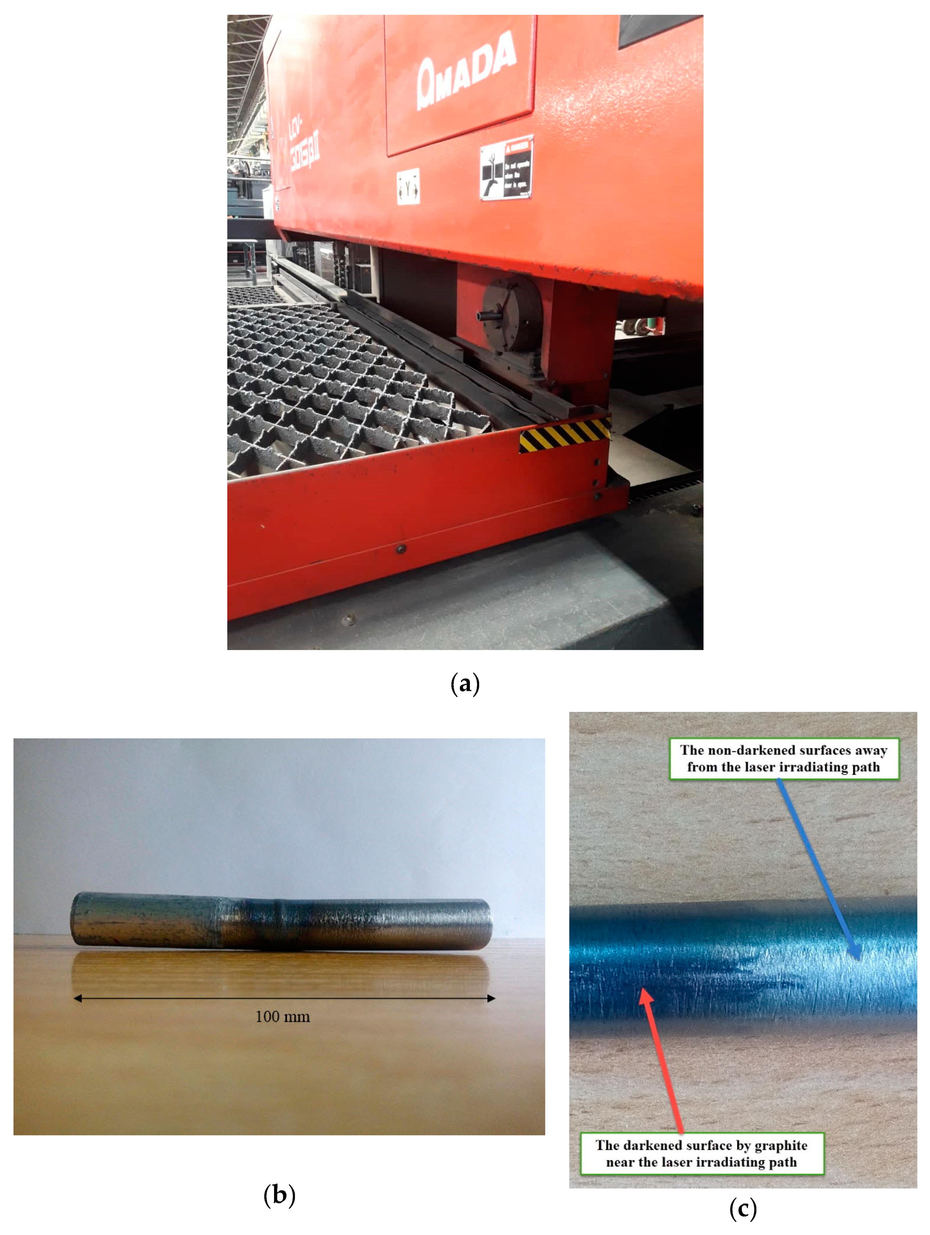
2. Experimental Work

Laser tube bending tests have been performed with an AMADA CO2 continuous laser (LASMAC LCV 3015, AMADA, Haan, Germany, model made in the USA). The maximum value of laser power is 4000 Watts. In the present work, mild steel tubes with a length of 144 mm, outer diameter of 18 mm, and thickness of 1 mm are bent with a laser beam. In Figure 1a, the laser machine employed in the laser tube bending experiments, and in Figure 1b, a sample of laser-bent tubes in the experimental tests, are shown. Due to increasing the absorptivity degree of the irradiated surface, the outer surface of the tube has been darkened by graphite (Figure 1c). A MITUTOYO coordinate measuring machine (CRYSTA-Apex V544 CMM CNC, MITUTOYO, Kawasaki, Japan) is employed for measuring the main and lateral bending angles, ovality percentage, and variations in the wall thickness of the laser-bent tubes. The tube is placed in a specified fixture and the coordinate of tube points is measured and the measured point cloud processed in CATIA software, P3 V5 R21, Dassault Systèmes, Vélizy-Villacoublay, France. In addition, the tube is cut by wire electrical discharge machine (WEDM, wire-cut, FANUC, Oshino, Japan) and the coordinate of cross-section is measured. The ovality and variation of wall thickness can be calculated by Equations (1) and (2). The ovality occurs due to the distribution of tensile and compressive stresses in the extrados and intrados surfaces of the laser-bent tube. The ovality percentage can be calculated from Equation (1) as follows:
O v a l i t y ( % ) = D max D min D × 100
In Equation (1), Dmax and Dmin are the maximum and minimum diameters in the cross-section of the bent tube and D is the initial diameter of the undeformed tube. In addition, the distribution of tensile and compressive stresses in extrados and intrados surfaces of laser-bent tubes leads to the appearance of a thickness distribution in the tube wall. The thickness variation ratio (TVR) of the laser-bent tube can be calculated from Equation (2) as follows:
T V R = T h i c k n e s s a t h i g h e s t p o i n t o f i n t r a d o s T h i c k n e s s a t h i g h e s t p o i n t o f e x t r a d o s
It should be noted that the lateral bending angle is an undesirable phenomenon that occurs due to unbalancing the temperature distribution at the start and endpoint of the irradiating path. It leads to a decrease in dimensional accuracy of the laser-bent tube and turbulence in fluid flow that passes through the tube.
In Figure 2a, the main and lateral bending angles for a laser-bent tube are shown schematically. Additionally, in Figure 2b, the main bending angle relevant to Y-displacement for a laser-bent tube is shown schematically. Accordingly, the main bending angle of each laser-bent tube can be calculated by Equation (3). The lateral bending angle can be calculated as being similar to the main bending angle.
B e n d i n g a n g l e = tan 1 ( Y d i s p l a c e m e n t ( m m ) 50 )
In the present work, the effects of the irradiating scheme on characterizations of the laser-bent tube such as main and lateral bending angles, ovality, and thickness variations at the cross-section of bending position are investigated. For this purpose, two irradiating schemes including circular and axial irradiating patterns are proposed. In the circular irradiating scheme (CIS), the circumferential paths with different arc lengths are irradiated with the laser beam in the middle of the tube length. In the axial irradiating scheme (AIS), the outer surface of the tube is irradiated from the middle of the tube to its free edge with lengths corresponding to the size of the arcs in the circular irradiating scheme. In Figure 3, the schematics of the circular irradiating scheme (CIS) and axial irradiating scheme (AIS) are shown. The length of irradiation (arc length and longitudinal length) varies from 4.7 mm to 28.2 mm (from 30° to 180° angular position). So, 10 samples were prepared according to the irradiation scheme and irradiation length of Table 1. It should be noted that the length of irradiation is equal in AIS and CIS.
It should be noted that in this paper, the aim is to compare CIS and AIS irradiating schemes in LTBP. Therefore the laser parameters in all experiments, and for both CIS and AIS irradiating schemes, are similar and equal to laser output power = 1100 W, laser scanning speed = 15 mm/min, and laser beam diameter = 6 mm. Additionally, the cooling conditions are similar for all the experiments. The tubes have been cooled to room temperature without forced convection and similar convection conditions have been used in both heating and cooling steps. Neither water jets nor gas jets were used for cooling. The tube material, laser power, scanning speed, and beam diameter were selected according to previously published articles of authors, which are kept constant to discuss the effects of the irradiation scheme in the current work.

3. Results and Discussion

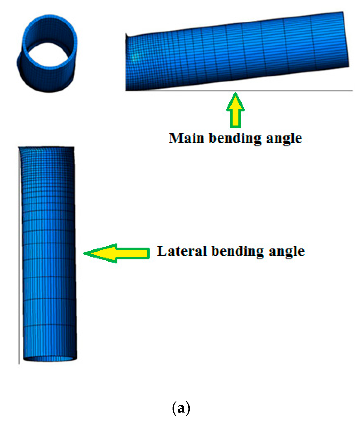
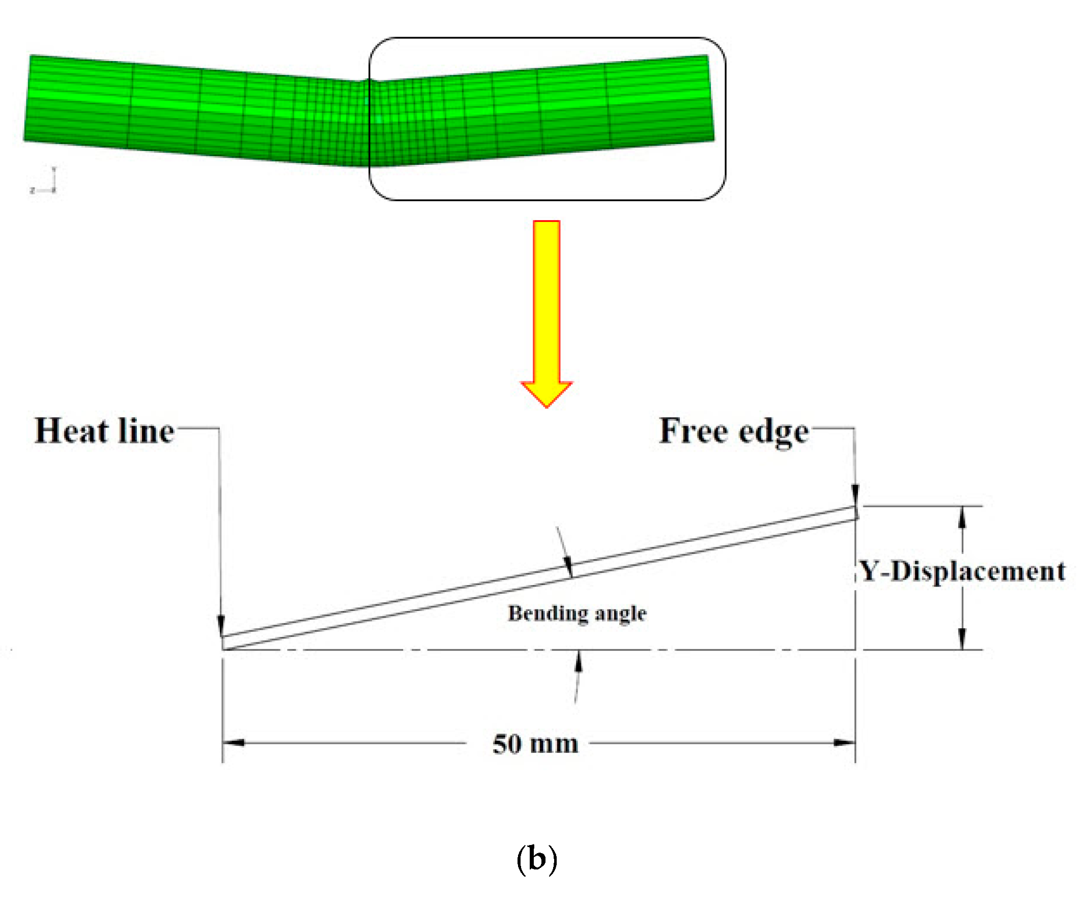
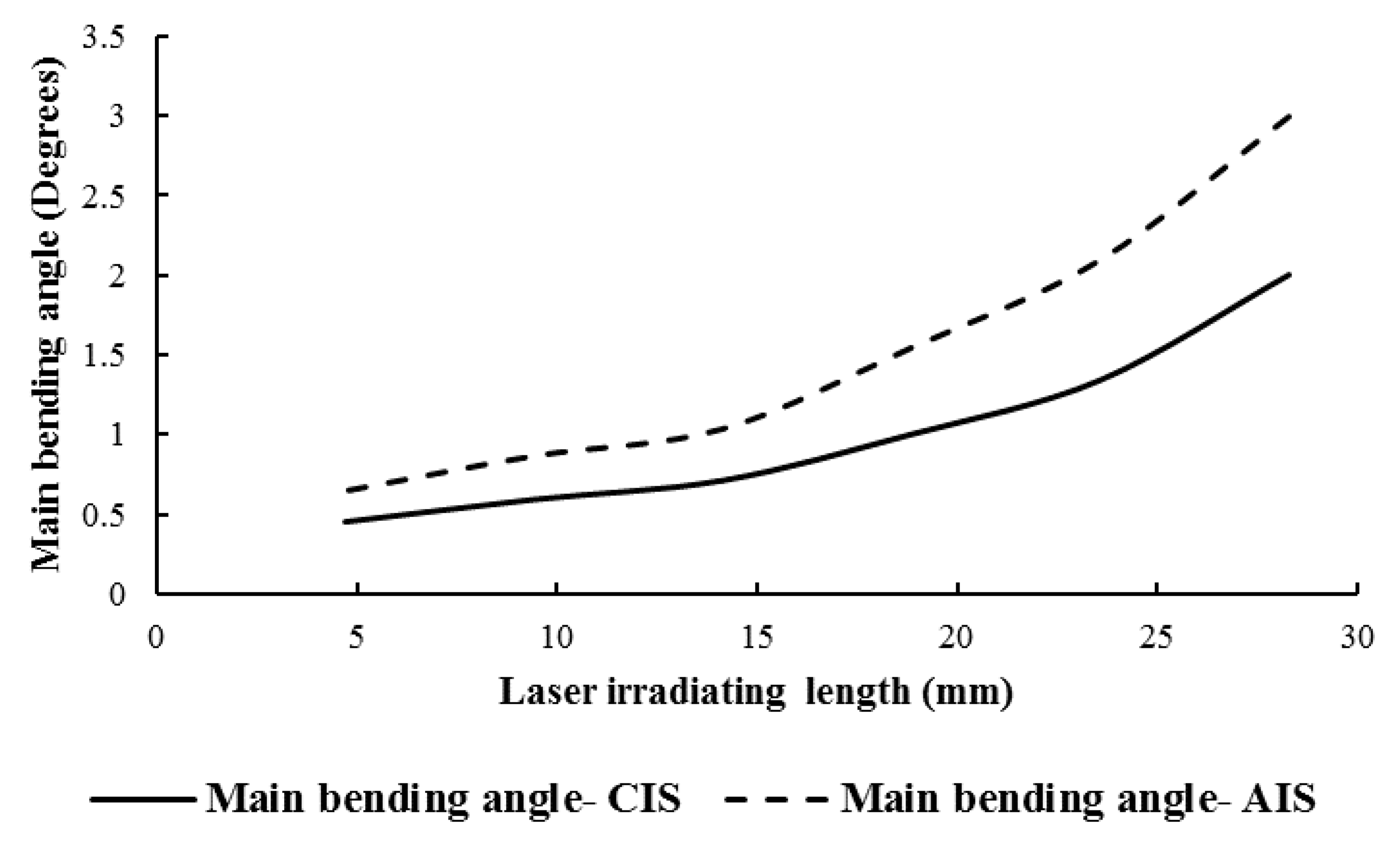
3.1. Effect of Irradiating Scheme on Main Bending Angle

In Figure 4, the effects of the circular irradiating scheme (CIS) and axial irradiating scheme (AIS) on the main bending angle of the laser-bent tube are presented. As it is seen, in both irradiating schemes, by increasing the irradiating length the main bending angle of the bent tube with the laser beam is increased. The reason is that by increasing the irradiating length, the plastic areas of the irradiated tube are noticeably increased and consequently the main bending angle is increased. In addition, it is concluded from Figure 4 that for a similar irradiating length, the obtained main bending angle with the axial irradiating scheme is considerably more than the obtained main bending angle with a circular irradiating scheme. This is because, in the circular irradiation scheme, the plastic strains are created in only one section through the tube length, while in the axial irradiation scheme, the plastic strains are created in different sections along the length of the tube. In other words, in the axial irradiation scheme, the sum of plastic strains created in different sections leads to the main bending angle in the laser-bent tube, while in the circular irradiation scheme, the plastic strains of one section lead to the main bending angle. Hence, the obtained main bending angle with the axial irradiating scheme is noticeably more than the bending angle associated with the circular irradiating scheme.

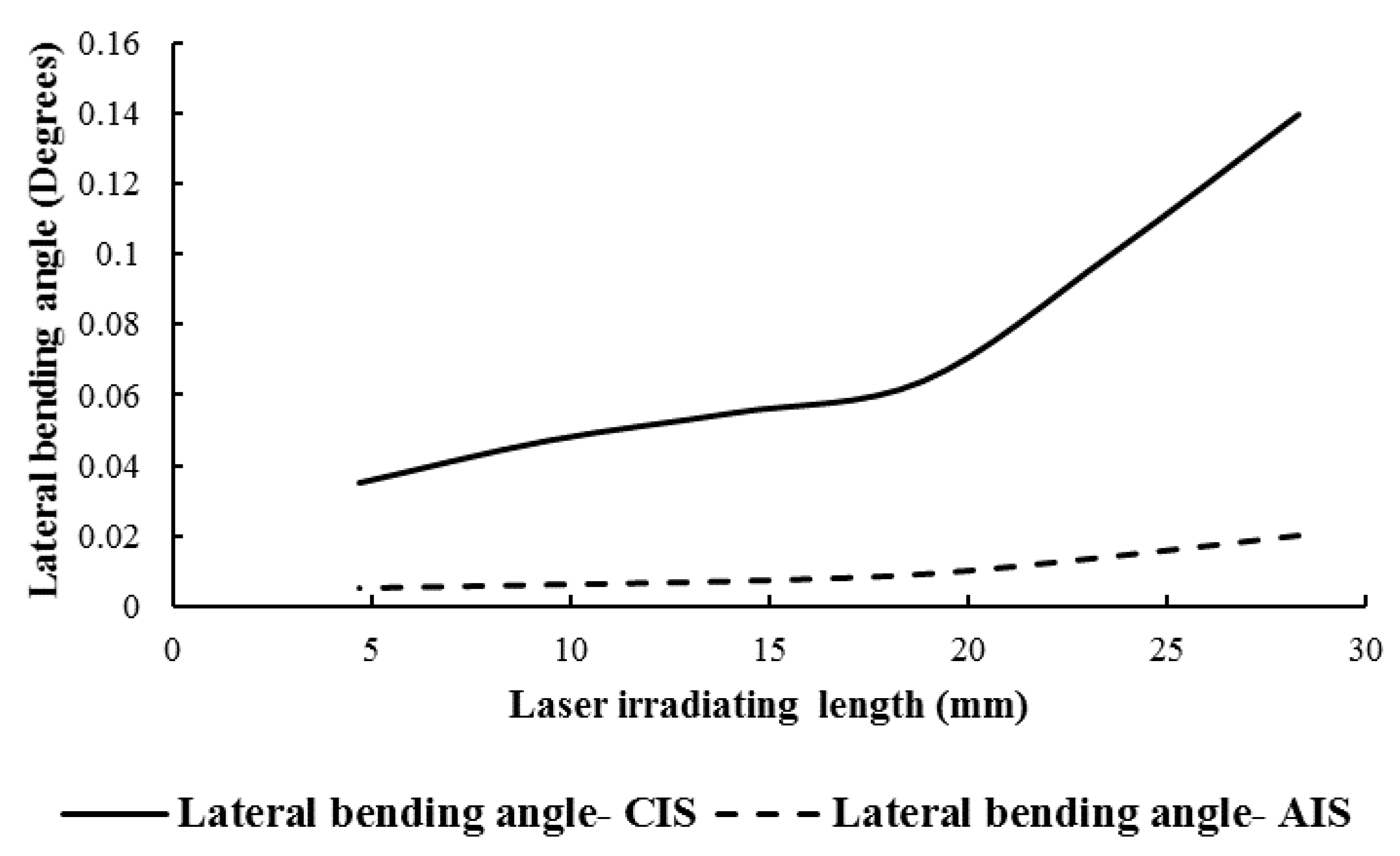
3.2. Effect of Irradiating Scheme on Lateral Bending Angle

The effects of the circular irradiating scheme (CIS) and axial irradiating scheme (AIS) on the lateral bending angle of the laser-bent tube are indicated in Figure 5. As it is shown in Figure 5, the associated lateral bending angles with both circular irradiating scheme and axial irradiating scheme are increased by increasing the irradiating length. For the circular irradiating scheme, the reason is that by increasing the irradiating length, more plastic areas are created in the middle cross-section of the tube, thus increasing the stiffness of the laser-bent tube and eventually increasing the lateral bending angle. For the axial irradiating scheme, it should be noted that irradiating each area leads to the appearance of the plastic strains in various directions. Therefore, in addition to the main bending angle, the tube is bent in other directions, and due to this bending in other directions, the lateral bending angle happens in the laser-bent tube. Increasing the irradiating length leads to more plastic strains in directions other than the main direction, and eventually the lateral bending angle increases. The deformation mechanism of the tube is plastic strain induced during heating and cooling. By increasing the temperature, softening happens in certain areas, as the plastic strain induced during heating and cooling leads to geometrical deformation of the tube. By increasing the length of laser beam radiation, more plastic deformation zones will be created and the shape of the final product depends on the irradiation scheme and laser source specification. More details can be found in [18]. In addition, it is proved from Figure 5, that the obtained lateral bending angle by axial irradiating scheme is much less than the obtained lateral bending angle with the circular irradiating scheme for all values of irradiating lengths. The reason for this is that in the circular irradiation scheme, the distance of the irradiated areas from the tube axis is much greater than the axial irradiation scheme, and therefore the effects of stiffness that lead to lateral bending of the tube are much more pronounced and finally, the lateral bending angle in the CIS is more than the AIS.

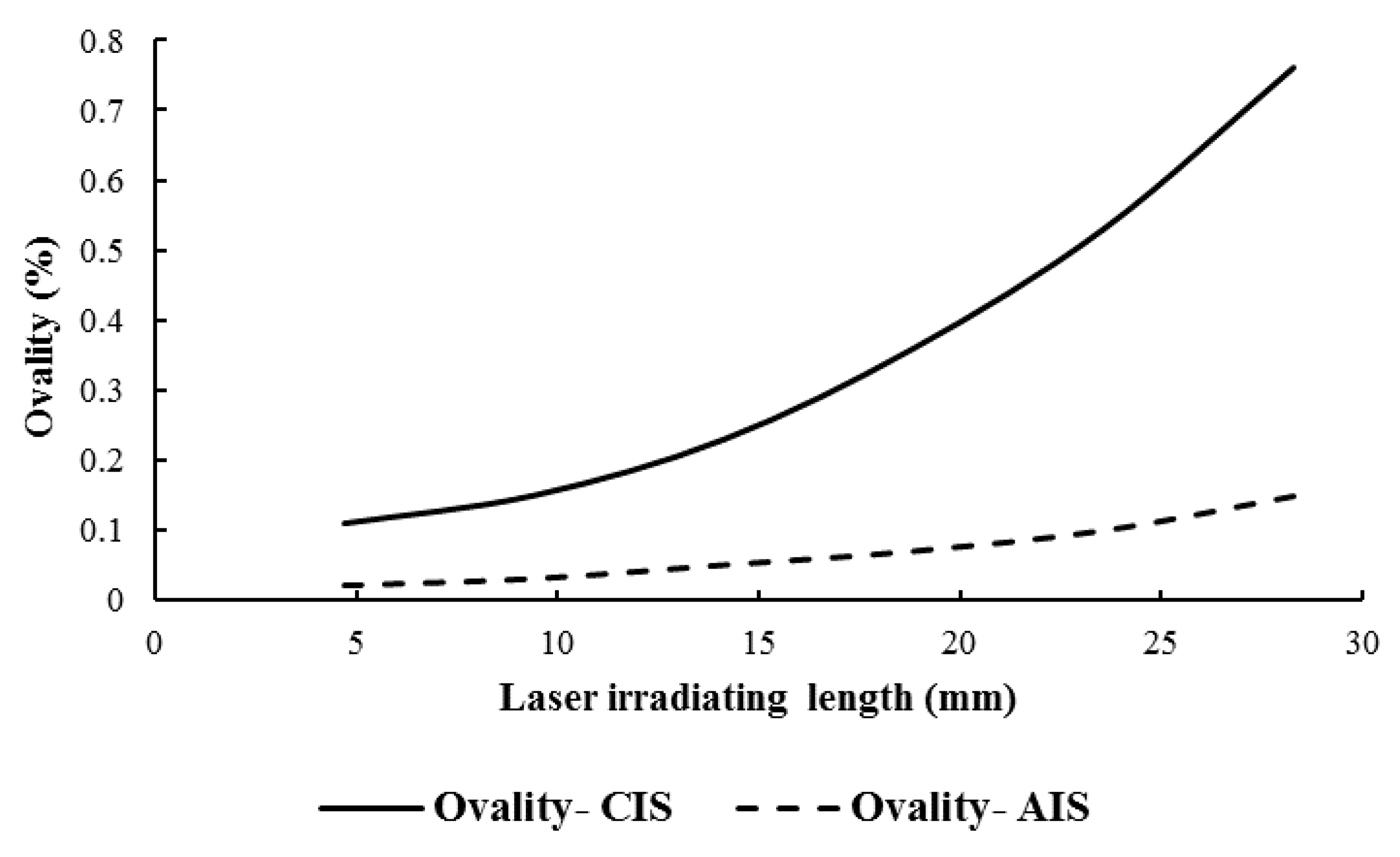
3.3. Effect of Irradiating Scheme on the Ovality of Laser-Bent Tube

In Figure 6, the effect of irradiating schemes on the ovality percentage of the fabricated tube by the laser beam is indicated. The ovality percentage of the laser-bent tube has been calculated from Equation (1). A precise tube was prepared for experimental testing and the ovality of the initial tube was 0.02 %. It is proved from Figure 6 that by increasing the irradiating length in the circular irradiating scheme (CIS), the ovality of the laser-bent tube is increased. This is because by increasing the irradiating length, more plastic deformations are created in the areas of the tube and consequently the variations in the tube diameter are noticeably increased. Hence, the ovality of the laser-bent tube is considerably increased. In addition, it is concluded from Figure 6 that the ovality percentage of the laser-bent tube is increased with an increase in the irradiating length by the axial irradiating scheme (AIS). The reason is that by increasing the irradiating length in AIS, several cross-sections will be affected during heating and cooling, and higher plastic deformation areas are produced and consequently the variations in the diameter of the tube are increased. More details about plastic deformation in laser bending are available in [18]. Therefore, the ovality percentage of the laser-bent tube is increased by increasing the irradiating length in the axial irradiating scheme.
In addition, from Figure 6 it is concluded that the ovality percentage for the laser-bent tube obtained by circular irradiating scheme is much more than the ovality percentage of the bent tube by a laser beam with the axial irradiating scheme for all values of irradiating lengths. The reason for this is that in the circular irradiating scheme, the irradiated areas in the central cross-section of the tube are much larger than the irradiated areas in the axial irradiating scheme. Therefore, the changes in the diameter of the tube that lead to the tube ovality are much greater, and finally, the ovality in the circular irradiating scheme is significantly greater than the axial irradiating scheme.

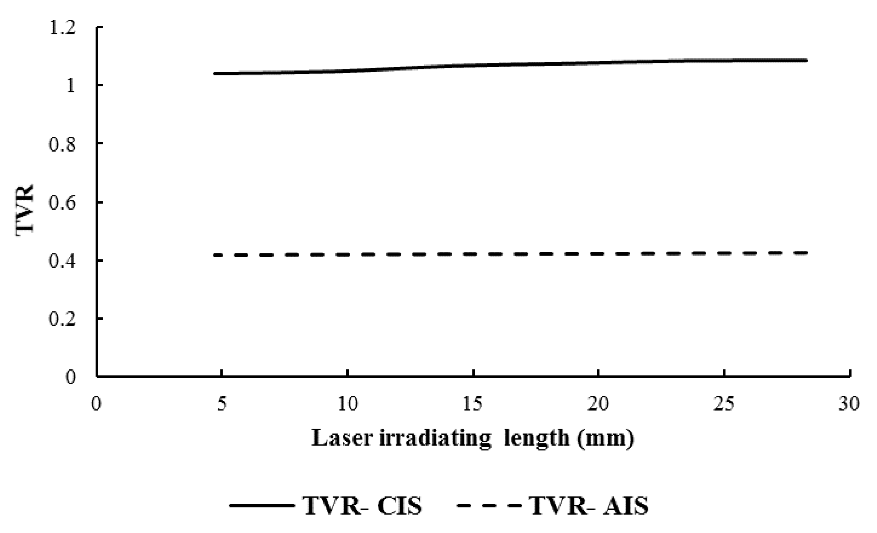
3.4. Effect of Irradiating Scheme on Thickness Variation Ratio of Laser-Bent Tube

In Figure 7, the effects of the irradiating scheme on the thickness variation ratio (TVR) of the laser-bent tube are presented. The thickness variation ratio has been calculated from Equation (2). It is proved from Figure 7 that for both CIS and AIS irradiating schemes with changes in the irradiating length, very little change is made in the thickness variation ratio of the laser-bent tube, while with changes in the irradiating length, the magnitude of ovality changes, as well as the main and lateral bending angles, were high. In addition, it is shown in Figure 7 that for similar irradiating lengths, the thickness variation ratio for the laser-bent tube with the circular irradiating scheme is considerably much more than the thickness variation ratio for the laser-bent tube with the axial irradiating scheme. The reason for this is that in the circular irradiating scheme, the irradiated areas in the central cross-section of the tube are much larger than the irradiated areas in the axial irradiating scheme. Therefore, the changes in the tube thickness are much greater in the circular irradiating scheme. For the measured thickness variation ratio of the laser-bent tube by the circular irradiating scheme, it can be concluded that by increasing the irradiating length the TVR is increased slightly. The reason for the increase relates to the formation of the plastic zones in the cross-section of the tube, which was discussed previously. For the measured thickness variation ratio of the laser-bent tube by the axial irradiating scheme, it can also be proved that by increasing the irradiating length the TVR is increased due to an increase in the plastic deformation areas.
In the circular irradiating scheme, the circumferential paths with different arc lengths were irradiated with the laser beam in the middle of the tube length. In the axial irradiating scheme, the outer surface of the tube was irradiated from the middle of the tube to its free edge with lengths corresponding to the size of the arcs in the circular irradiating scheme. In addition, the effects of irradiating schemes on some main defects of the laser-bent tube such as lateral bending angle, ovality, and thickness variations of the tube were studied.

4. Conclusions

In this paper, LTBP was investigated and the effects of the irradiating scheme and the irradiation length on the main bending angle of the laser-bent tube were studied. For this purpose, two irradiating schemes including circular irradiating scheme (CIS) and axial irradiating scheme (AIS) were proposed. The main outcome of this study can be emphasized as follows:
1. The main bending angle with AIS was considerably higher than the obtained bending angle with CIS for a similar irradiating length. This is due to inducing plastic strains in several sections in AIS compared to inducing the plastic strain in just one cross-section. In addition, the lateral bending angle with AIS was much less than the obtained lateral bending angle with CIS because of stiffness effects.
2. The main bending angle of the bent tube increased by increasing the irradiating length in both irradiating schemes because of the higher plastic deformation zone in the irradiated tube. In addition, a similar increase was observed for lateral bending angles because of higher stiffness and plastic strain effects.
3. The circular irradiating scheme leads to a higher ovality percentage and higher thickness variation ratio compared to AIS for similar irradiation length. The concentration of heat in one cross-section leads to higher deformations in the plastic areas and eventually more ovality and tube thickness changes for irradiating with CIS.
4. By increasing the irradiating length in both CIS and AIS, the ovality of the laser-bent tube was increased due to increasing the plastic deformation of irradiated areas and consequently the variations of the tube diameter. Very little change was made in the thickness variation ratio of the laser-bent tube, while with changes in the irradiating length, the magnitude of ovality changes as well as the main and lateral bending angles were high.
5. The authors believe that the main shortcoming in laser tube bending is the complexity of geometry and lack of investigations in different irradiation schemes. For example, a discontinuous helix irradiation scheme with different pitches leads to deformation in the tube. Most of the researchers focused on sheet bending. Mechanically assisted laser tube bending is another interesting topic for future studies by the authors.

Author Contributions

Conceptualization, investigation, and methodology, M.S.; formal analysis and funding acquisition, R.J.A.d.S.; validation and writing—original draft preparation, J.J.; writing—review, and editing, M.S., R.J.A.d.S. and J.J. All authors have read and agreed to the published version of the manuscript.

Funding

Ricardo J. Alves de Sousa acknowledges grants UID/EMS/00481/2019-FCT and CENTRO-01-0145- FEDER-022083-Centro2020, European Regional Development Fund (ERDF).

Institutional Review Board Statement

Not applicable.

Informed Consent Statement

Not applicable.

Data Availability Statement

Data available on request.

Conflicts of Interest

The authors declare no conflict of interest.

References

  1. Safari, M.; Alves de Sousa, R.; Joudaki, J. Fabrication of saddle-shaped surfaces by a laser forming process: An experimental and statistical investigation. Metals 2020, 10, 883. [Google Scholar] [CrossRef]
  2. Khandandel, S.E.; Seyedkashi, S.M.H.; Moradi, M. Numerical and experimental analysis of the effect of forced cooling on laser tube forming. J. Braz. Soc. Mech. Sci. 2021, 43, 338. [Google Scholar] [CrossRef]
  3. Wang, X.Y.; Wang, J.; Wang, L.J.; Xu, W.J.; Guo, D.M. Scanning path planning in laser bending of tube based on curvature. Adv. Mater. Res. 2011, 264, 6–11. [Google Scholar] [CrossRef]
  4. Li, F.; Liu, S.; Shi, A.; Shi, Q.; Li, Y. Research on laser thread form bending of stainless steel tube. Int. J. Precis. Eng. Manuf. 2019, 20, 893–903. [Google Scholar] [CrossRef]
  5. Folkersma, G.; Brouwer, D.; Römer, G. Microtube laser forming for precision component alignment. J. Manuf. Sci. Eng. 2016, 138, 081012-1–081012-6. [Google Scholar] [CrossRef]
  6. Khandandel, S.E.; Seyedkashi, S.M.H.; Moradi, M. A novel path strategy design for precise 2D and 3D laser tube forming process; experimental and numerical investigation. Optic 2020, 206, 164302. [Google Scholar] [CrossRef]
  7. He, Y.; Li, H.; Zhang, Z.; Guangjun, L. Advances and trends on tube bending forming technologies. Chin. J. Aeronaut. 2012, 25, 1–12. [Google Scholar] [CrossRef] [Green Version]
  8. Khandandel, S.E.; Seyedkashi, S.M.H.; Hoseinpour Gollo, M. Effect of cooling on bending angle and microstructure in laser tube bending with circumferential scanning. Iran. J. Mater. Form. 2020, 7, 14–23. [Google Scholar] [CrossRef]
  9. Safari, M. A study on the laser tube bending process: Effects of the irradiating length and the number of irradiating passes. Iran. J. Mater. Form. 2020, 7, 46–53. [Google Scholar] [CrossRef]
  10. Keshtiara, M.; Golabi, S.; Tarkesh Esfahani, R. Multi-objective optimization of stainless steel 304 tube laser forming process using GA. Eng. Comput. 2021, 37, 155–171. [Google Scholar] [CrossRef]
  11. Imhan, K.I.; Baharudin, B.T.H.T.; Zakaria, A.; Ismail, M.I.S.B.; Alsabti, N.M.H.; Ahmad, A.K. Investigation of material specifications changes during laser tube bending and its influence on the modification and optimization of analytical modeling. Opt. Laser Technol. 2017, 95, 151–156. [Google Scholar] [CrossRef]
  12. Che Jamil, M.S.; Imam Fauzi, E.R.; Juinn, C.S.; Sheikh, M.A. Laser bending of pre-stressed thin-walled nickel micro-tubes. Opt. Laser Technol. 2015, 73, 105–117. [Google Scholar] [CrossRef]
  13. Wang, X.Y.; Wang, J.; Xu, W.J.; Guo, D.M. Scanning path planning for laser bending of straight tube into curve tube. Opt. Laser Technol. 2014, 56, 43–51. [Google Scholar] [CrossRef]
  14. Guan, Y.; Yuan, G.; Sun, S.; Zhao, G. Process simulation and optimization of laser tube bending. Int. J. Adv. Manuf. Technol. 2013, 65, 333–342. [Google Scholar] [CrossRef]
  15. Hao, N. On the process parameter of laser tube bending. In Proceedings of the 2010 International Conference on. Mechanic Automation and Control Engineering (MACE), Wuhan, China, 26–28 June 2010; pp. 5880–5883. [Google Scholar] [CrossRef]
  16. Zhang, J.; Cheng, P.; Zhang, W.; Graham, M.; Jones, J.; Jones, M.; Yao, Y.L. Effects of scanning schemes on laser tube bending. J. Manuf. Sci. 2006, 128, 20–33. [Google Scholar] [CrossRef] [Green Version]
  17. Hsieh, H.S.; Lin, J. Study of the buckling mechanism in laser tube forming. Opt. Laser Technol. 2005, 37, 402–409. [Google Scholar] [CrossRef]
  18. Li, W.; Yao, Y.L. Laser bending of tubes: Mechanism, analysis, and prediction. J. Manuf. Sci. 2001, 123, 674–681. [Google Scholar] [CrossRef]
  19. Silve, S.; Steen, W.M.; Podschies, B. A Discussion of Principles. In Proceedings of the ICALEO on Laser Forming Tubes, Orlando, FL, USA, 16–19 November 1998; pp. 151–160. [Google Scholar]
  20. Kraus, J. Basic process in laser bending of extrusion using the upsetting mechanism. In Laser Assisted Net Shape Engineering 2, Proceedings of the LANE’97, Erlangen, Germany, 23–26 September 1997; Geiger, M., Vollertsen, F., Eds.; Meisenbach: Bamberg, Germany, 1997; Volume 2, pp. 431–438. [Google Scholar]
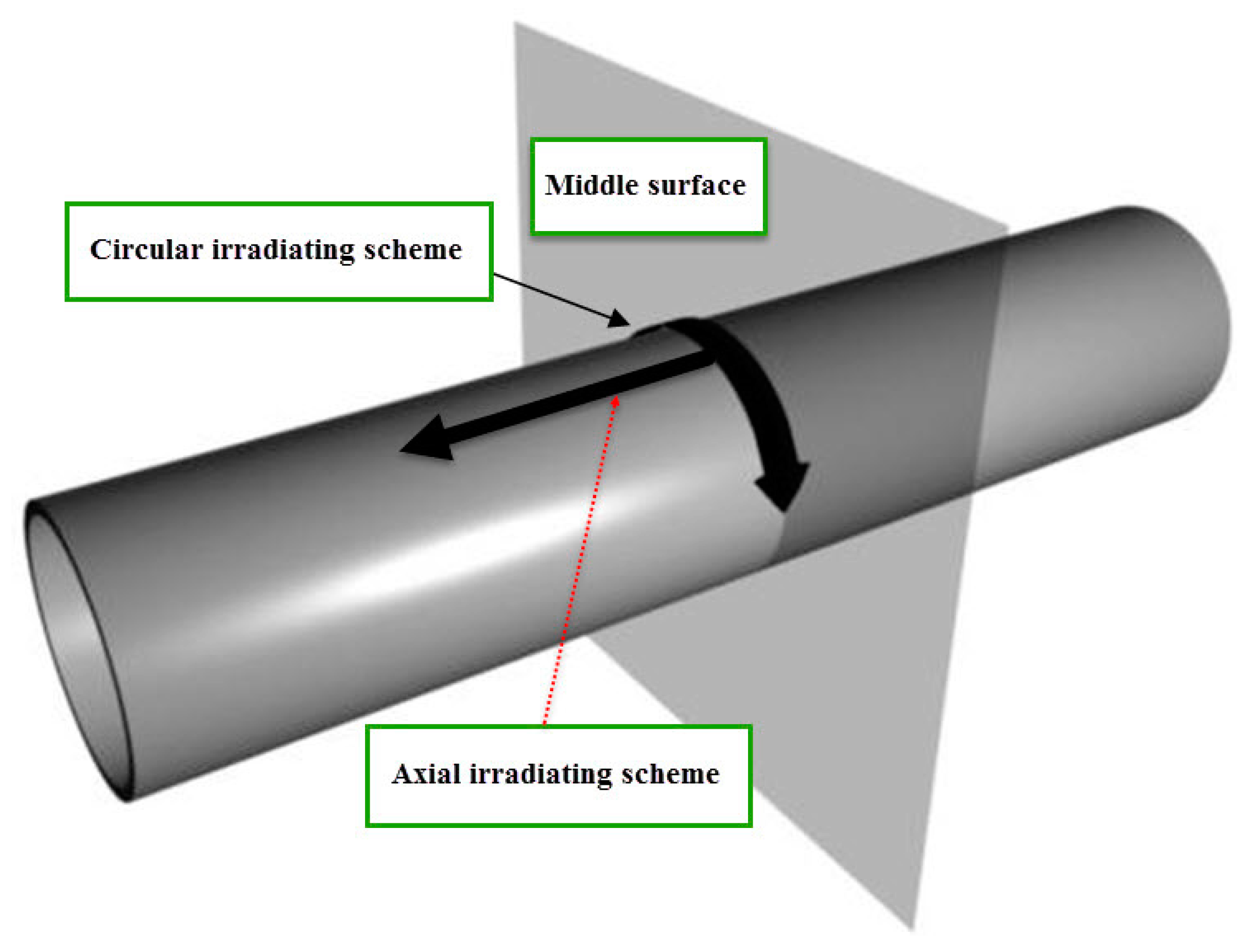
Figure 1. (a) The laser machine employed in the laser tube bending experiments; (b) a sample of laser-bent tubes in the experimental tests; (c) the darkened and non-darkened areas in a laser-bent tube.
Metals 11 01123 g001
Figure 2. (a) Schematic views of main and lateral bending angles, (b) Schematic view of the main bending angle relevant to Y-displacement for a laser-bent tube.
Metals 11 01123 g002aMetals 11 01123 g002b
Figure 3. The schematics of the circular irradiating scheme (CIS) and axial irradiating scheme (AIS).
Metals 11 01123 g003
Figure 4. The effects of the circular irradiating scheme (CIS) and axial irradiating scheme (AIS) on the main bending angle of the laser-bent tube.
Metals 11 01123 g004
Figure 5. The effects of the circular irradiating scheme (CIS) and axial irradiating scheme (AIS) on the lateral bending angle of the laser-bent tube.
Metals 11 01123 g005
Figure 6. The effect of irradiating schemes on the ovality percentage of laser-bent tubes.
Metals 11 01123 g006
Figure 7. The effects of irradiating scheme on thickness variation ratio (TVR) of the laser-bent tubes.
Metals 11 01123 g007
Table 1. The irradiation scheme and irradiation length in experimental tests.
Irradiation SchemeIrradiation Length (Irradiation Angle)
Circular Irradiating Scheme (CIS)4.7 mm (30°)
9.4 mm (60°)
14.1 mm (90°)
Axial Irradiating Scheme (AIS)21.15 mm (135°)
28.2 mm (180°)
Publisher’s Note: MDPI stays neutral with regard to jurisdictional claims in published maps and institutional affiliations.

