Article

Enhancing Heat Treatment Conditions of Joints in Grade P91 Steel: Looking for More Sustainable Solutions

by
Vitor F. C. Sousa
1,
Francisco J. G. Silva
1,2,3,*,
António P. Pinho
1,
António B. Pereira
3 and
Olga C. Paiva
1
1
ISEP—School of Engineering, Polytechnic of Porto, Rua Dr. António Bernardino de Almeida, 431, 4200-072 Porto, Portugal
2
INEGI—Instituto de Ciência e Inovação em Engenharia Mecânica e Engenharia Industrial, Rua Dr. Roberto Frias, 400, 4200-465 Porto, Portugal
3
TEMA—Centre for Mechanical Technology and Automation, Department of Mechanical Engineering, University of Aveiro, Campus Universitário de Santiago, 3810-193 Aveiro, Portugal
*
Author to whom correspondence should be addressed.
Metals 2021, 11(3), 495; https://doi.org/10.3390/met11030495
Submission received: 20 February 2021 / Revised: 11 March 2021 / Accepted: 15 March 2021 / Published: 17 March 2021
(This article belongs to the Special Issue Welding: State-of-the-Art 2021)

Abstract

:
Grade P91 is a relatively new class of steel, which has received special attention from designers because it presents extremely interesting characteristics for specific applications. This steel exhibits ideal properties for demanding applications, especially involving high temperature and pressure, being employed in facilities such as power plants and other equipment, such as heat exchangers. P91 welds usually need heat treatments, which are already parameterized in the codes. However, standardized treatments are time-consuming and harmful to the environment, as they massively consume energy. Some attempts have been made in the past to reduce the time and energy spent on these treatments. This work aims to extend this study, now presenting better solutions than those obtained previously. This work presents four new conditions for the heat treatment of joints carried out on P91 steel, with a view to reducing processing time, reducing energy consumption, and an even better balance between mechanical strength and elongation after failure. Heat treatment conditions were established in which there was a loss of about 14% in Ultimate Tensile Strength (UTS), but in which a gain of about 50% in elongation was obtained, compared to welding without any treatment, but also with 10% losses in the UTS and 30% gains in elongation when compared to the solution recommended as more correct in the codes, saving a lot of time and energy in the treatment process. Thus, these solutions may be adopted in the future with gains in terms of productivity and economic and environmental sustainability.

1. Introduction

Welding continues to be one of the most studied manufacturing techniques within the metalworking field. Due the diversity of materials that can be joined by this technique, the multiplicity of existing processes, the high range of parameters involved, and the high number of defects whose can be generated, this process requires proper planning and execution [1,2]. These studies assume particular relevance whenever a new welding process is developed, such as in the case of the Friction Stir Welding process [3], or some variant of them is explored, or even when any material assumes special importance in applications where welding becomes unavoidable. These studies can take on more experimental or simulation components, with the latter strand gaining more and more importance due to the fact that the software is increasingly evolved, and this technique allows significant gains in time and material resources [4]. Despite this, it is common for simulations to start from data obtained experimentally, or to proceed with the validation of the simulation through experimental results.
The first steels with 12% Cr date from the 1960s in the 20th century. However, these steels have traditionally presented creep problems when used under hard work conditions, which prevented their use in certain more demanding applications, such as power plants boiler construction, main steam pipelines, heat furnace piping in petrochemical industry and heat exchangers. This type of facilities usually works with temperatures between 570 and 600 °C, as well as pressures around 200 bar, which requires high mechanical strength and creep resistance. The loss of mechanical properties was essentially associated with the formation of modified Z-phase, due to the formation of nitrides of Cr (V, Nb) in steels with 9–12% Cr when exposed for a long time to temperatures in the range of 600–700 °C [5]. Previous studies proved that these modified phases were induced more easily the greater the content of Cr in the alloy. Thus, subsequent developments have undergone a reduction in Cr content from 12% to 9%, being originally developed by the Oak Ridge National Laboratory and initially designated as P9 [6,7]. Over the years, other alloying elements (V, Nb) were added since they are strong carbide formers, giving the designation P91 to the material [6]. In order to overcome the creep problems presented by that type of steels, the P91 steel grade has been developed, which consists of a chemical composition based on 9% Cr−1% Mo, enriched with molybdenum, vanadium and niobium, and in which the nitrogen content is strictly controlled, thus giving way to a new class of steels capable of withstanding the demanding working conditions required by the aforementioned applications [8]. Studies have shown that creep behavior is strongly governed by the content of some alloying elements, such as Cr, Mo, V, Nb and W. When the balance between the contents is not the most appropriate, there may be a formation of δ-ferrite, which is undesirable because it leads to the deterioration of the mechanical properties of the alloy [9]. However, the correct combination of these elements also promotes excellent resistance to oxidation and corrosion, as well as elevated fatigue life and creep resistance under relatively high temperature conditions [10]. P91 grade can be considered as an evolution of the P22 grade, which it came to replace, being able to assume different designations, such as T91 (corresponding to the seamless tube) and P91 (when in the form of seamless pipe), ASTM A335 for plates, according to ASTM, or X10CrMoVNb9-1 according to BS EN 10216-2 [11]. Indeed, P91 grade presents excellent properties, such as high strength even under elevated temperatures, good corrosion resistance, stress-corrosion crack resistance, low thermal expansion, high thermal conductivity, and good weldability, thus having the main properties required by the most demanding applications mentioned above [12,13]. In fact, the excellent mechanical strength at high temperatures comes from martensite transformation induced dislocations, tempered martensite lath structure, boundary strengthening, as well as the formation of M23C6 precipitates. These are induced by the presence of Cr, Mo, Fe and MX precipitates derived from the presence of V and Nb (M), and C and N (X), and solid solution strengthening from molybdenum [13]. It is these precipitates that can be subject to changes during prolonged exposure to elevated temperatures, which may cause some degradation of the microstructure initially constituted, and a degeneration in time of the properties that initially characterize this type of steel. Kim et al. [14] also refer that prolonged exposure to high temperatures leads to a progressive degradation of its microstructure, due to coarsening of carbide precipitates and also to the precipitation of Laves-phases and modified Z-phases, which deteriorates the excellent mechanical properties initially exhibited.
Equipment such as boiler superheat tubes, heat exchangers or power plants are equipment or facilities that contain immense piping, which is normally made of P91 steel and connected using welding and several welding processes have been used to joint P91 steel both in similar joints and dissimilar ones, mainly with P92. Indeed, Marzocca et al. [15] used flux cored arc welding (FCAW) process utilizing E91T1 and E91T1-G rutilic flux-cored wires as filler metals. In that study, M23C6 carbides and vanadium-based precipitates were found across the bead. Additionally, shielded metal arc welding (SMAW) and submerged arc welding (SAW) have also been used to increase the welding effectiveness of P91 steels, but the results were not satisfactory, with the detection of non-metallic inclusions in the weld beads, some loss of toughness, and excessively high oxygen content in the welds [16,17]. Trying to optimize productivity when welding this type of steel, the A-TIG (Activated Tungsten Inert Gas) technique has also been used by several researchers [18,19]. Indeed, the thin activated flow layer used in the A-TIG has proved to increase the productivity comparing it to the conventional TIG (Tungsten Inert Gas) process [18]. In fact, depending on the flux type used, also the penetration can be drastically improved, being reported values as 200% when CeO2 flux is used, or 300% when MoO3 flux is utilized. The use of the A-TIG technique has also been associated with a slight increase in Ultimate Tensile Strength (UTS) and in the hardness in the weld beads, compared to the base material. More advanced processes have also been used to weld P91 steels, such as autogenous laser beam [20] and electron beam [21], but some concerns have been reported in both cases, such as the formation of δ-ferrite in the first case, with consequent softening of the weal bead due to the strong heat input generated by the process, or high residual stresses in the second case, mainly when higher thicknesses are welded.
The instability and lack of homogeneity of the microstructure formed along the welds, as well as problems related to the formation of residual stresses, the diffusible hydrogen content in the joints, and the formation of intermetallic phases, has led to the need to carry out heat treatments to minimize the effects of these problems on the deterioration of welded joints [9]. Thus, several studies have been carried out trying to find the best conditions to weld P91 steels and achieve the best mechanical performance, keeping the remaining desirable properties, such as corrosion resistance and thermal conductivity. Pandey et al. [9] recently studied the weldability of P91 steels, concluding that one of the main problems in the deterioration of fatigue and creep resistance at high temperature is the amount of diffusible hydrogen carried to the welded joint. To avoid diffusible H in the joint, they suggested all the solutions already usually recommended and carried out in practice: pre-heating the base material, baking the electrodes and selecting low hydrogen electrodes. However, to eliminate problems related to the failure by creep due to microstructural instability in the joint, they found that the best solutions are to add B and W to the joint, perform a half-temper, or perform heat-treatments to normalize the microstructure. In another study also conducted by Pandey et al. [22], the dissimilar welding of P91 with P92 was tested, observing the formation of δ-ferrite agglomerates when the welding was used with TIG autogenous welding, different of the observed when using TIG with filler metal. δ-ferrite creates soft areas, with deterioration of mechanical properties, and is also insensitive to the performance of Post Weld Heat Treatment (PWHT). These authors also found that by increasing the duration of PWHT, there was a continuous decrease in hardness, since PWHT promotes a reduction in hardened and tempered martensite. It was also found that when the TIG process is accompanied by the addition of filler metal, the same temperature can be used for PWHT (760 °C), but the duration of the treatment must be much shorter, i.e., only 2 h, while welding TIG autogenous require treatment at the same temperature, but for 6 h, in order to reach the toughness level usually required, i.e., 47 J. Another study carried out by the same team [23], but this time using shielded metal arc welding (SMAW), allowed to quantify the maximum level of diffusible H that the P91 joints may contain without hydrogen embrittlement. This value was established at 6.21 mL/100 g. Higher values result in increased porosity in the joints and a progressive loss of toughness presented by the joints. The fractures took place essentially in areas where it was possible to detect MnS and secondary phase carbide particles. The authors also state that the normalization/tempering treatment, if carried out under conditions of low diffusible H, is that which promotes greater homogeneity of the microstructure throughout the weld, giving rise to better mechanical properties, and presenting better results than the treatment of PWHT. Another study [24] carried out with a view to determining the best type of treatment to be applied to P91 steel welds showed that better mechanical properties can be achieved using re-austenitizing at 1040 °C for 60 min and air-cooled and tempered at 760 °C for 2 h, followed by air cooling. This treatment was compared with a PWHT performed at 760 °C for 2 h and finally air cooled, verifying that the creep rupture life was about 600% higher than the second one (PWHT), and about 140% higher than the samples untreated (as-welded state). Different temperatures and times have been repositioned for the PWHT of P91 steels, varying between 760 °C and 770 °C, and lasting around 2 h [25,26]. Recently, a study was carried out in order to optimize the cycle of heat treatments to be applied to welds made of P91 steel [27], given that the treatments recommended by the metal building codes are complex and unfriendly to the environment, consuming immense energy and being a time-consuming task. Several strategies have been established and alternatives were pointed out to the set of complex treatments recommended in the building codes. This work aims to extend the knowledge brought by that work, establishing new conditions for heat treatments, and analyzing the advantages and drawbacks of these new strategies, taking into account the mechanical properties obtained, the time consumed by the heat treatment cycle and the energy consumed in those same treatments.

2. Materials and Methods

2.1. Materials

As in the previously performed work [27], the experimental work was conducted on a SA 355 P911 steel pipe, with 48.3 mm in diameter and 5 mm thickness, which was provided by Vallourec Brazil (Belo Horizonte, Brazil). The material’s mechanical properties and chemical composition are presented in Table 1 and Table 2, respectively.
From the pipe material 25 welds were produced, with 150 mm in length and one tip of the pipe chamfered. This number of samples was chosen to provide at least five samples per destructive test. Two sets of five samples were created from the material, one from Pipe 1 and the other Pipe 2; these were from the same material (P91), the chemical composition of which will be described later in this article. The welds were performed using a filler metal. A 2 mm diameter rod (reference ER90s-B9) was used, provided by Electro Portugal, Lda. (Porto, Portugal). The rod’s chemical composition can be observed in Table 3. This filler metal was selected as it is recommended by the ASME (The American Society of Mechanical Engineers) manufacturing code for this type of material.

2.2. Methods

The main objective of this paper remains the same as the one presented in the paper by Silva et al. [27], being the evaluation of the various heat treatment cycles on the grade P91 steel welded joints, looking for obtaining a more favorable thermal cycle and expanding the knowledge about this process with this base metal. The pipes were first cut in a circular sawing machine Kaltenbach KKS 450 S (Kaltenbach GmbH, Lorrach, Germany), and the chamfer was made using a conventional lathe, Knuth V-Turn Pro (Knuth Werkzeugmaschinen GmbH, Wasbek, Germany). After the initial preparation, the samples were then cleaned, avoiding the presence of contaminants and chips, resulting from the last step.
Regarding the welding process of these samples, GTAW has been used in the 2G position, using a Kemppi (Kemppi, Lahti, Finland) Master TIG MLS 400 multi-power source welding machine. Prior to the weld, the samples were properly aligned, furthermore, thermocouples were attached to the sample’s surface, close to the weld joint. Regarding the chosen parameters, these were the same as the ones used in the previously presented paper [27], with a heat input of 1.33 kJ/mm being selected and a current intensity of 95 A (this was selected taking the thickness of the filler-metal wire into account). Table 4 shows the welding parameters used for the conducted experimental work.
For the application of the various heat-treatments to the welded joints, a Weldotherm (Weldotherm, Esse, Germany) VAS 82-12 Digit 1000 Heat Treating Unit with 12-channel capacity was used, with half of these channels being capable of using electrical resistances consuming 135 A, and the rest of the channels being capable of using electrical resistances consuming 90 A.
In this paper, different thermal cycles were applied to the various welded samples in order to evaluate their influence in the joint’s mechanical properties. These different thermal cycles can be observed in Figure 1 (the reference coding of these cycles is also displayed in this figure, being the same as the one presented in [27]). Table 5 provides information on the temperature that was used in the different thermal cycles. This information was obtained from two thermal couples that were placed in two opposite extremities of the pipe (placed in the interior of the Pipes 1 and 2, during the welding procedure). These positions are A (for the top part of the pipe) and B (for the bottom part). Next, the different cycles will be presented, mentioning the main reasons for their application in this study:
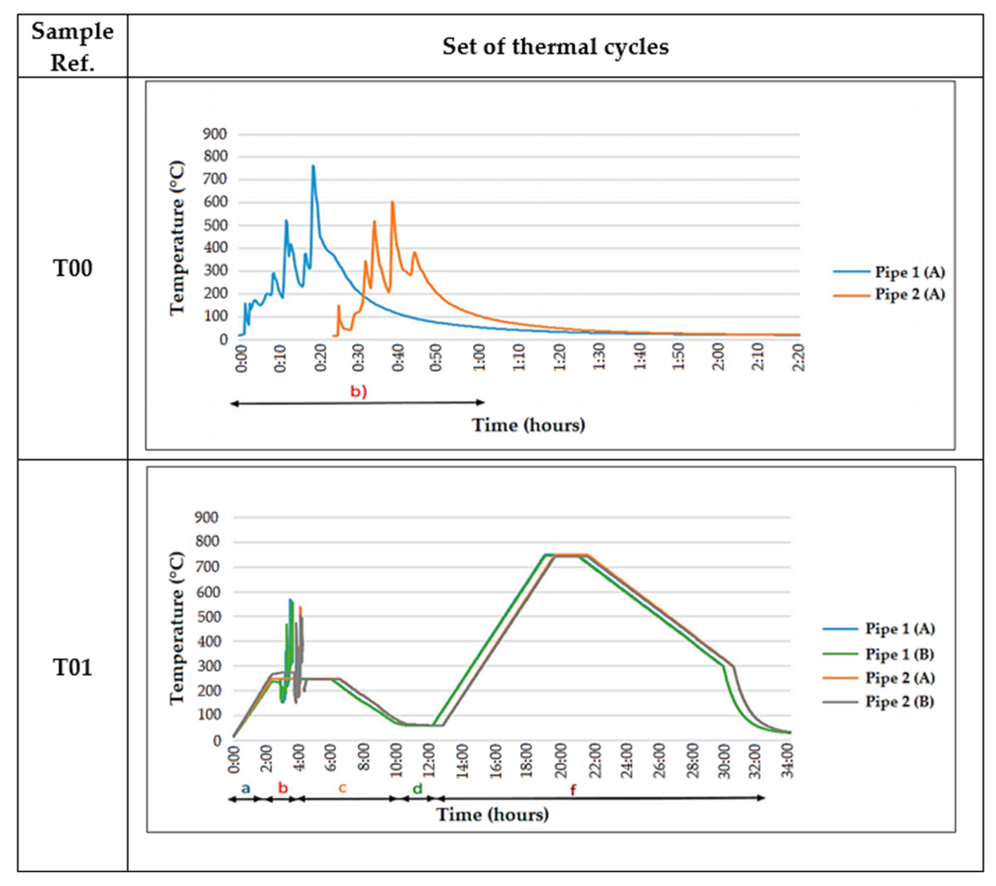
  • T00: These samples were used without any kind of heat-treatment. They were also used in the previously presented paper [27], as a means of comparison and as a way to evaluate what happens when the best practices are not applied. No heat-treatments have been made in these samples;
  • T01: Like the previous thermal cycle, this was also included in the paper [27]. This procedure is the one recommended by construction codes, standards, and manufacturers (that work with P91 steel welded joints). This cycle includes pre-heating, welding, post-heating, transformation time and finally, a PWHT. This procedure is very time and energy consuming, being classified as unproductive and environmentally unfriendly;
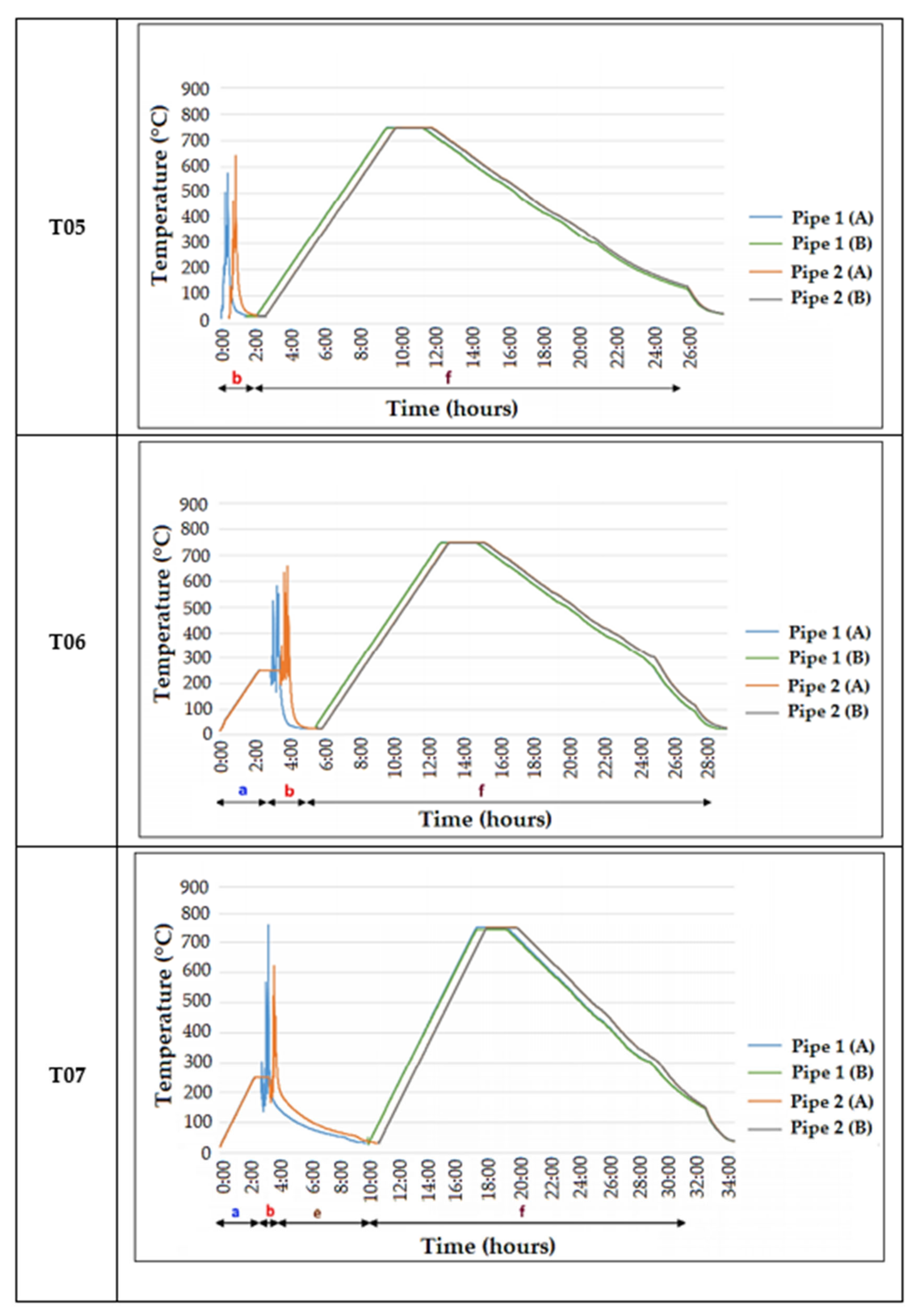
  • T05: This thermal cycle does not have any pre-heating, with only a PWHT being applied after cooling of the weld. The procedure was conducted as means to see if only a PWHT would be enough to improve the joint’s mechanical properties and behavior.
  • T06: The samples subjected to this thermal cycle were obtained by applying a pre-heating of the joint, followed by welding and, finally, the PWHT, similarly to the previous procedure, the weld was left to cool at room temperature;
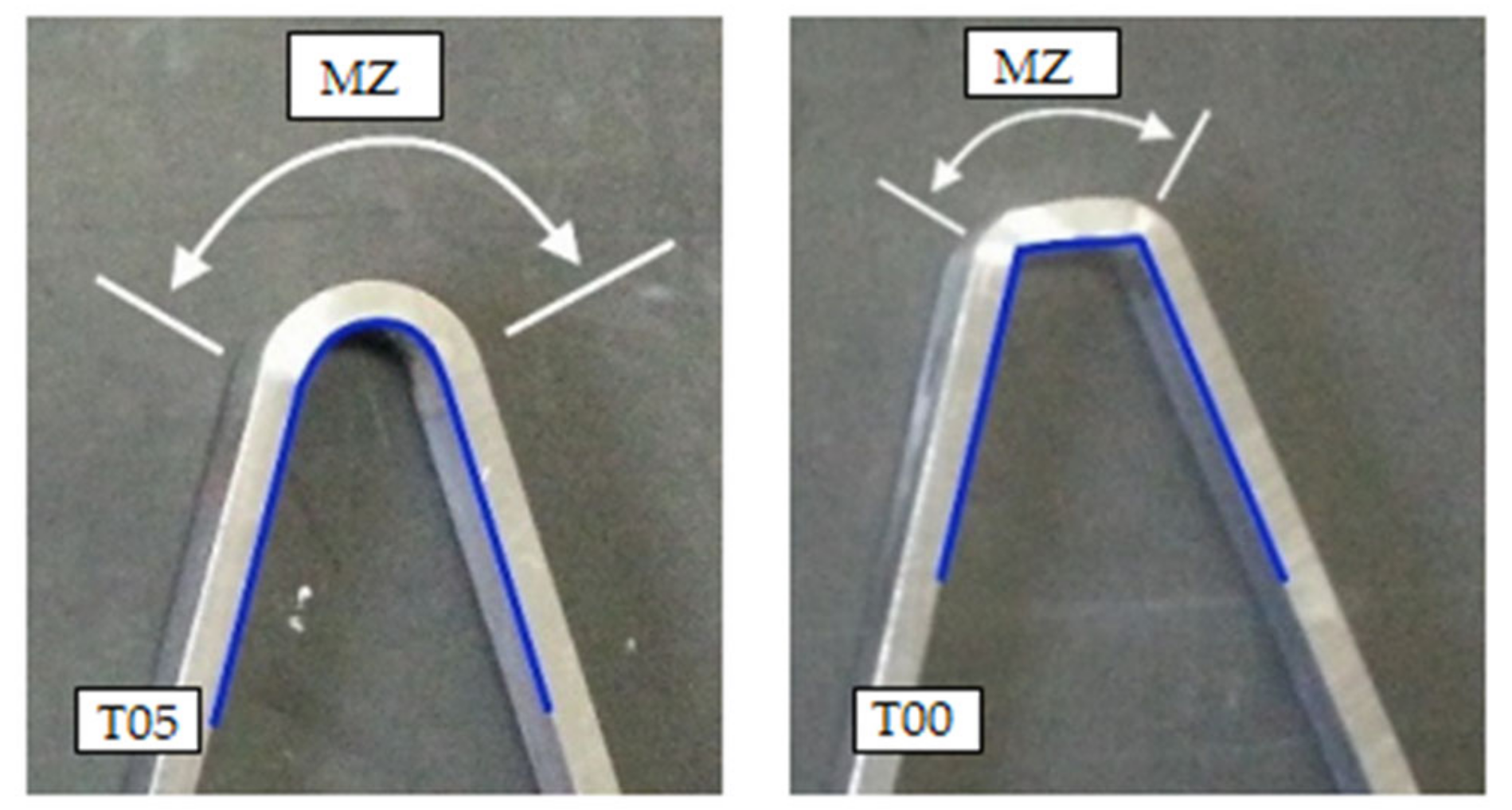
  • T07: This is a very similar procedure to that of the T06 samples, with the only difference being the cooling time after the weld. In this case, a ceramic fiber was used to envelop the welded tube, thus increasing the cooling time of the weld. This difference can be observed in Figure 1;
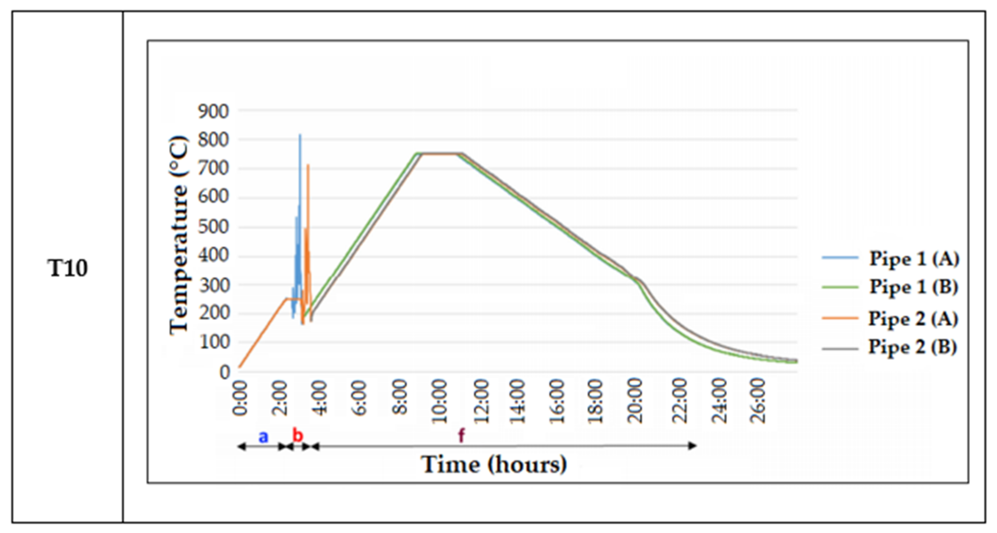
  • T10: In this procedure, the samples were submitted to a pre-heating and a PWHT, being very similar to the previously presented procedures. However, in this case, the samples were subjected to the PWHT immediately after welding, essentially skipping the weld cooling step. Furthermore, by performing the PWHT right after welding, there is no need for a post-heating step (as seen in T01), which is usually preformed to remove the Hydrogen that is present in the weld. This “skip” would reduce the heat-treatment of these welds by around 10 h, making this thermal cycle very appealing for the treatment of these steels, provided that the mechanical properties exhibited by the weld are satisfactory.
The setups associated with the different thermal cycles have already been described and shown in the previously presented paper [27]. This is also the case for the welding setup.
Following the application of the various thermal cycles to the welded samples, these were characterized. The characterization approach was equal to those of [27], where the various procedures are described in more detail. These samples were subjected to several analyses, from non-destructive to destructive testing. All of these tests and the equipment used to carry them out are presented below:
  • Liquid penetrant testing: Used after the chamfer preparation, it was used to check for superficial defects, following the standard ISO 3452-1:2013 [28];
  • Visual testing: This test was carried out immediately after the welding process, checking for external defects and following the standard ISO-17637:2003 [29]
  • X-ray analysis: Analysis carried out to check for internal defects, using a ICM machine (RAYZORXPRO-X23, Saint-Aubin-les-Elbeuf, France) with 300 kVA. The standard ISO 20769-2:2018 was followed for this procedure.
  • Hardness surface testing: Initial hardness assessment was performed with portable equipment Krautkramer—MIC 10 (Kastllaun, Germany), provided with a MIC 205-A probe, following the standard ASTM E110 [30];
  • Bending tests: Tests were performed using a CIATA press machine, model P-115/HP (Vila Nova de Gaia, Portugal), following the standard ASME IX-QW136 [31]
  • Tensile testing at 20 °C: For the mechanical characterization of the samples, tensile tests were performed on a universal testing machine, Instron 4208 (Norwood, MA, USA), according to the standard ASME IX: 2015-QW 150 [32]
  • Tensile testing at 600 °C: For the mechanical characterization of the samples tensile tests were performed on a universal testing machine, Instron 4208 (Norwood, MA, USA), according to the standard ISO 6892-2:2018 [33]
  • Hardness profile (preformed along the cross-section of the welds): hardness characterization of the welds was performed with the equipment Krautkramer—MIC 10 (Kastllaun, Germany), provided with a MIC 205-A probe.
  • Chemical composition analysis: To analyze the chemical composition of the welded samples, an optical emission spectrometer Spectro was used, model Spectrolab M8 (Spectographic, Leeds, UK);
  • Electronic and optical microscopy: Microstructural analysis was carried out using an optical microscope model Axioskop 2 Mat (Carl Zeiss, Oberkochen, Germany); For electronic microscopy, the equipment used was a scanning electronic microscope FEI QUANTA (FEI, Hillsboro, OR, USA);
  • Microhardness testing: These hardness tests were carried out using a Shimadzu HSV-20 equipment (Shimadzu, Kyoto, Japan), following the NP EN 1043-1 [34] and the ISO 6507:2018 [35] standards.
Regarding the hardness assessment, three different tests were performed: hardness tests with portable equipment to carry out a first evaluation of the welded joints, a microhardness cross-section evaluation to assess the hardness reached in each zone of the joint, and finally another microhardness test allowing the detection of soft spots. A Krautkramer—MIC 10 equipment provided with a MIC 205-A probe was used because it was portable and easy to handle, providing results accurate enough regarding the level required at this stage, which was just a general previous evaluation. The load used to perform these tests was 49 N (5 kgf) with a dwell time of 30 s, and a diamond Vickers indenter with 136° was used to perform the indentations. To obtain more accurate results, further microhardness tests were carried out using Shimadzu HSV-20 equipment, following the NP EN 1043-1 [34] standard, using as load 98.1 N (10 kgf) and a Vickers diamond indenter. However, to do that, it was necessary to improve the surface roughness through a new polishing process with diamond slurry of 1 µm over 10 min to decrease the Rz roughness to values under 2 µm. Two rows of indentations were produced. Finally, the opposite surface of the same samples was prepared following the same procedure as well, to identify soft spots, close to the base material. These soft points are responsible for a decrease in creep resistance and are formed mainly in the fine grain region of the HAZ. Using the same microhardness equipment and indenter, these tests have been carried out using just 1 kgf (HV1) and a dwell time of 30 s, still following the ISO 6507:2018 standard [35]. Three rows of indentations were produced, one close to the weld root, another in the middle of the cross-section, and the last one close to the surface of the base material; all the indentations were distanced 0.5 mm each other, which is the minimum distance recommended by the standard.

3. Results and Discussion

3.1. Non-Destructive Test Results

The nondestructive tests performed served to evaluate the state of the samples, providing information on what sample would deserve a deeper analysis (such as destructive testing). All the samples analyzed by these non-destructive tests also underwent the destructive tests, listed above.

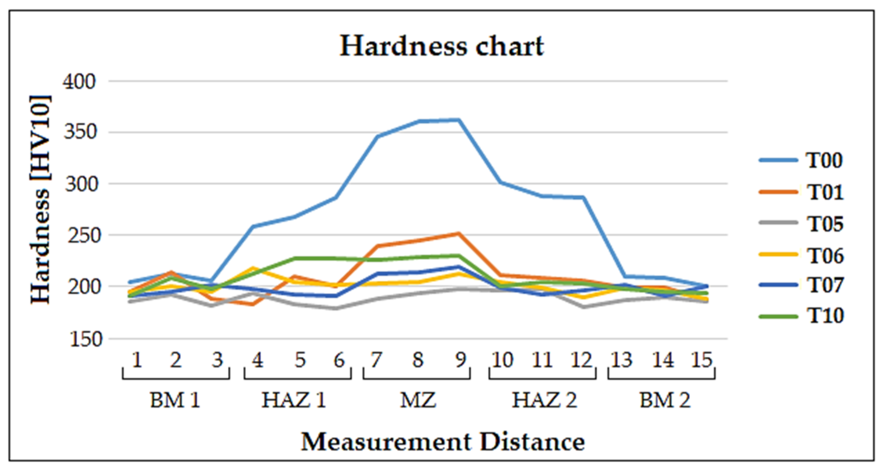
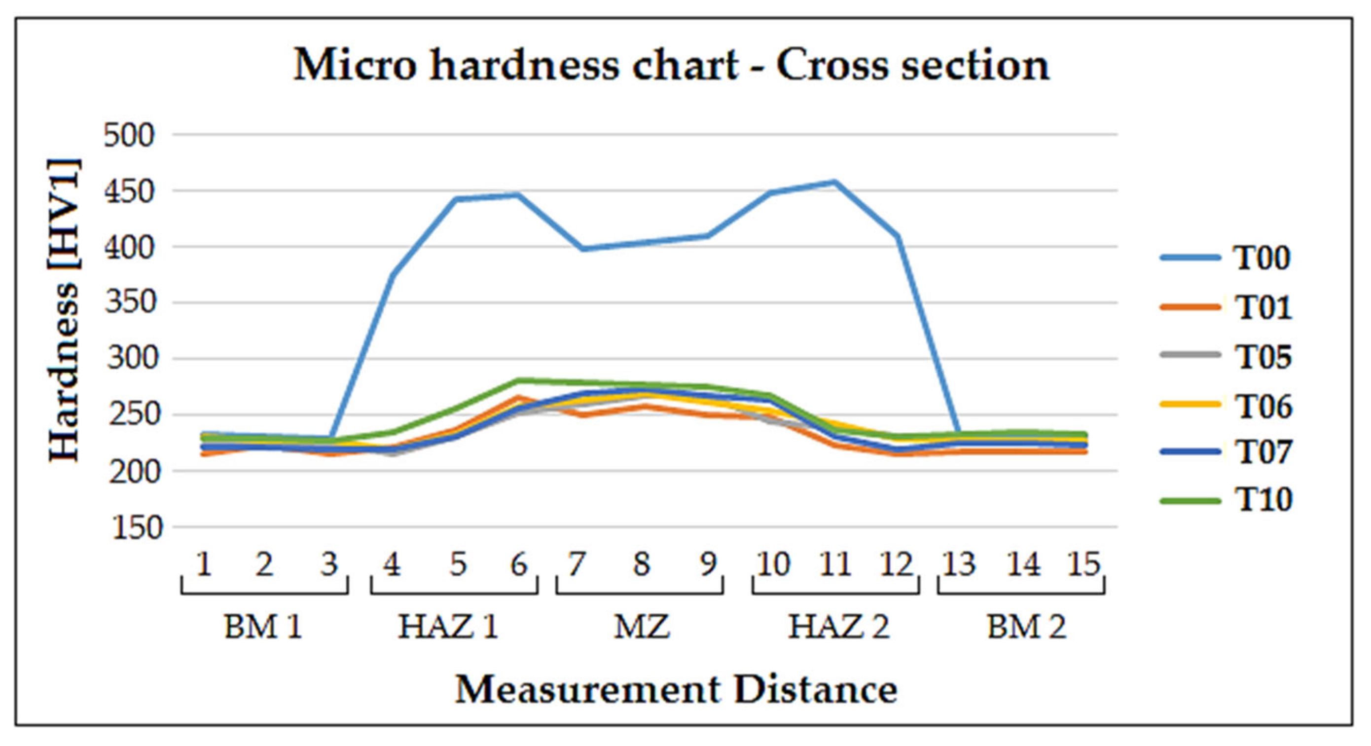
3.2. Hardness and Microhardness Analyses

These hardness tests allowed for the assessment of hardness values of the profile across the joint, from the base material 1 (BM 1) to the base material 2 (BM 2), passing through both the heat-affected zones 1 and 2 (HAZ 1 and HAZ 2) and the melted zone (MZ). The surface hardness registered values can be observed in Table 6 and the corresponding hardness profiles can be observed in Figure 2. Regarding the values displayed in Table 6, these were obtained from the average value of hardness registered per zone, whereas in Figure 2 (regarding the hardness profile) the hardness values are divided into three measurements per zone. These were the average values registered for both tested samples (Pipe 1 and 2). It can be observed that the hardness values in the HAZ and MZ were higher before PWHT, as the martensite was not yet tempered, being extremely hard and brittle in that state. This can be seen in the sample T00, where there was no application of a PWHT and the hardness values can be observed to be very high, especially in the HAZ and MZ, making these samples unsuitable for application [23]. Due to the accuracy of the equipment (explained in detail in [27]), microhardness tests were carried out. The hardness profile obtained from these tests can be seen in Figure 3, showing a clear example of the high hardness values of the T00 sample (in the HAZ and MZ).
These microhardness tests were also performed as means to identify possible soft spots in the cross-section of the welds. These soft spots are very small areas with a lower hardness than the base material or in the fine grain region of the HAZ (intercritical region). The hardness results obtained from the samples are summarized in Table 7. This intercritical region is located at the border of the HAZ, very close to the base material. This is where there is a possibility to occur Type IV cracks during the manufacturing stage or during the life of the welded component.

3.3. Weld’s Chemical Analysis

In order to verify the final composition of the weld, optical spectroscopy was used. However, as the chemical composition of the filler metal and the base material were very similar, it was expected that the weld exhibited a very similar composition to the base material and filler metal. The results from this analysis are displayed in Table 8.
It can be observed that the weld composition, both in the face and the root, were very similar to the compositions provided by the suppliers of the base and filler metal, thus concluding that the dilution of the welding process did not significantly impact the composition of the weld itself.

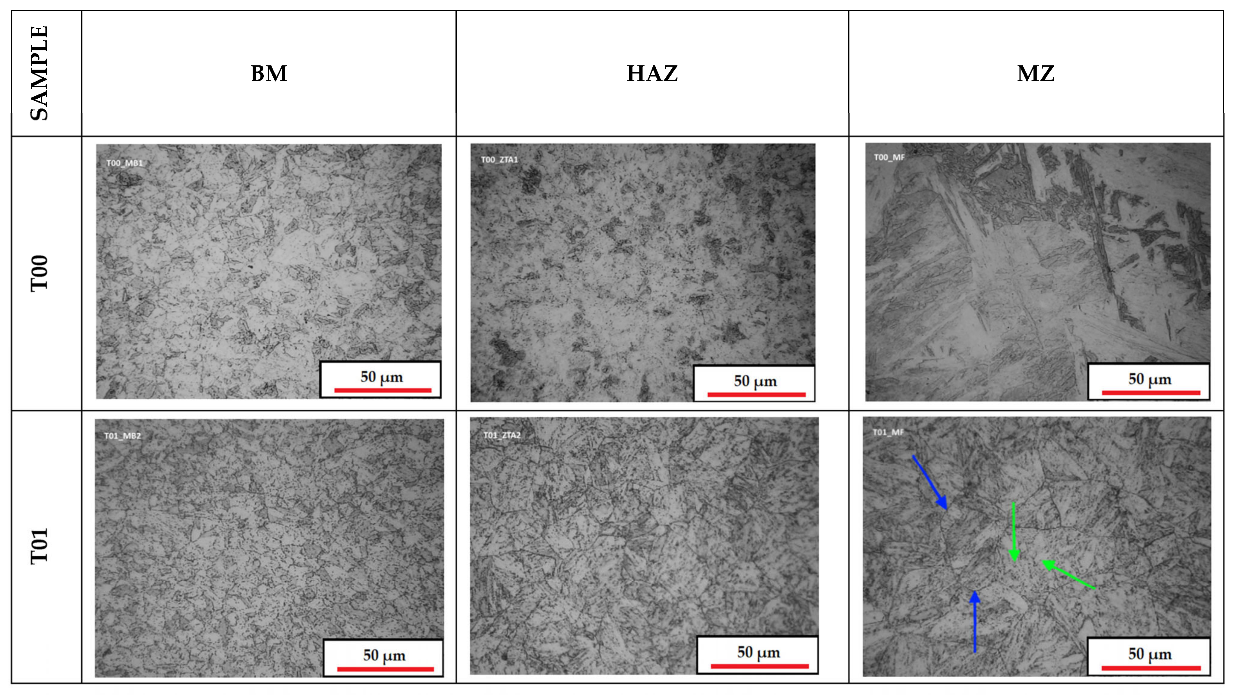
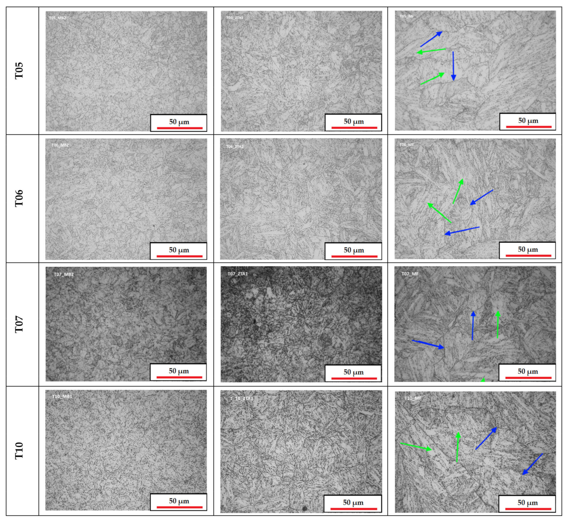
3.4. Microstructural Analysis

The various samples’ microstructures were analyzed using optical and electron microscopy. Assorted images of the different zones of the weld were taken with the most representative micrographs being presented in Figure 4. Studying the microstructure of these welds gives relevant information about the behavior of all the different weld zones.
As seen in the previous article [27], the microstructures of all samples consisted of tempered martensite, conferring excellent joint properties, except for the untreated sample (T00). The sample that underwent the recommended treatment had a typical grain size in the HAZ of about 20–30 µm, with this grain being larger in the MZ, with a size of about 60–70 µm. Moreover, in this sample the grains were well defined with clear areas of tempered martensite. Regarding sample T05, the microstructure was well defined as well, registering a change in grain size from the HAZ (finer) to the MZ (coarser), similar to what was seen in the sample T01; there was also the clear presence of precipitates such as M23C6, which is related to good mechanical properties [13]. The microstructure of the sample T06 was very similar to the one observed in T05, however, in this case there were zones of undefined grain boundaries registered in the microstructure, especially in the MZ. For the sample T07, the microstructure was also like the last two samples. However, there were more areas of undefined grain boundaries present in the MZ when compared to the T05. Moreover, grain coarsening was registered in HAZ 2, which is undesirable for the usual application targeted by this material. As for the last sample of this batch, T10, the grain size was observed to be quite regular throughout both HAZ, however, in the MZ there registered grains that ertr too big or too small, resulting in an abnormal discrepancy in grain size. Furthermore, there were some zones of undefined grain boundaries in the MZ of this sample.

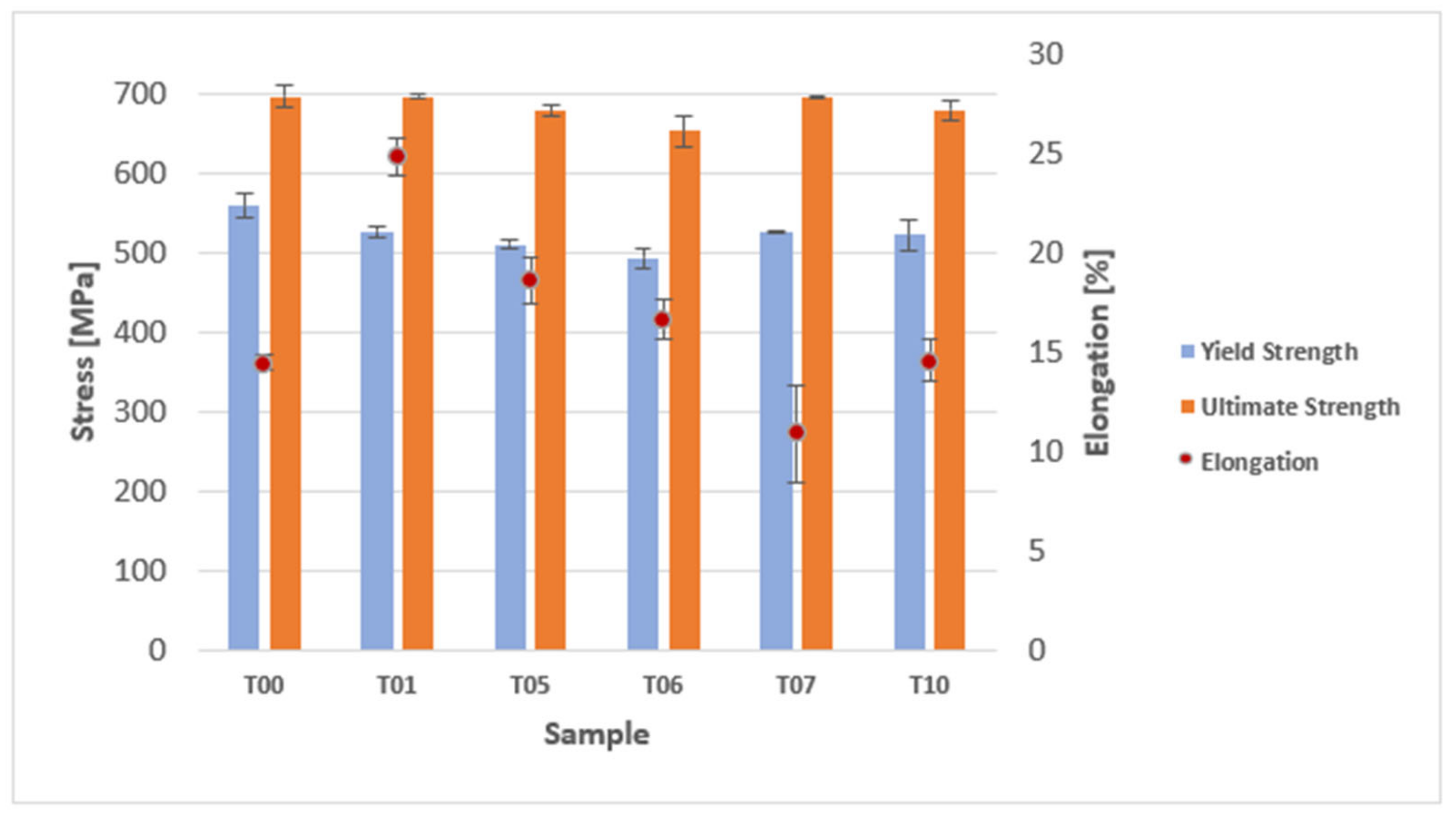
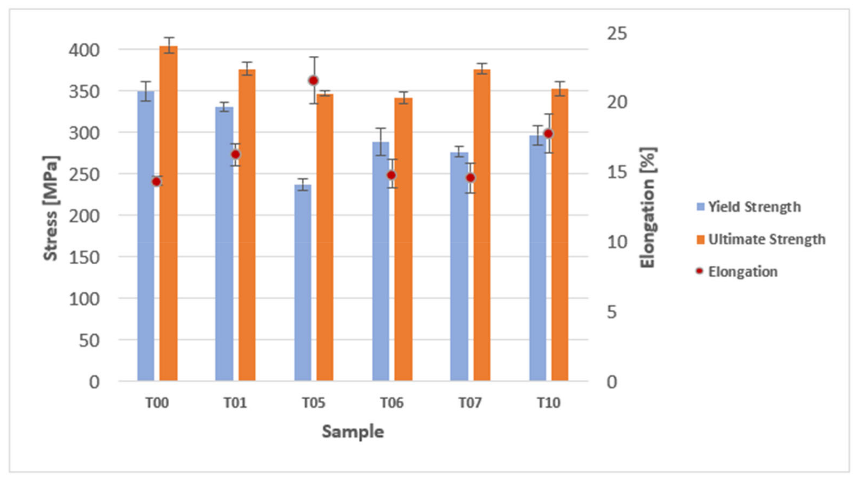
3.5. Tensile Tests at Room and High Temperature

As mentioned in the previously conducted paper [27], there is a minimum value for yield strength and ultimate tensile strength of welds of this material, determined by the ASME code B31.3—Process piping [36]. The values are: 413 MPa for minimum yield strength and 586 MPa for minimum ultimate tensile strength. These values are determined for room temperature tensile tests, the results from all the tests performed to the welded samples can be observed in Table 9.
It can be observed that all the tested samples surpassed the minimum values, and they all ruptured by the base material after testing. The values of yield strength and ultimate tensile strength for the T00 sample were quite high, this was expected as this sample was not heat treated [22]. However, this sample exhibited very low values of elongation. The results of the tensile tests performed at room temperature can be observed in Figure 5, under the form of a bar graph.
In terms of yield strength and ultimate tensile strength, it can be observed that the new samples exhibited values very close to that of the T01 sample, which was the reference for comparison (as it was the recommended treatment). The three samples that exhibited the values that were closer to the reference were T07, T05 and lastly T10. In terms of elongation, however, sample T07 exhibited a very low value, being lower than that of the untreated sample. The best sample in this regard was T05, exhibiting the highest value of elongation of all the new thermal cycles. Due to this, the sample T05 had a very high potential as a new way to heat treat this material, as it produced very close properties to those of the recommended heat-treatment, while skipping many steps of the procedure, also saving time and energy.
Regarding the tensile tests performed at high temperature (600 °C), there was also a minimum value for the yield strength, this being 71 MPa, with all the tested samples satisfying this requirement, as seen in Table 9. Furthermore, like in the tensile tests performed at room temperature, the samples exhibited rupture at the base material, away from the MZ and HAZ. In Figure 6, the results of these tensile tests are depicted in graphic form.
Similar to what was observed in the tensile tests performed at room temperature, the samples exhibited close values of yield strength and ultimate tensile strength to the sample that underwent the recommended thermal cycle. However, in this case, the value for elongation was also close, for most of the newly tested samples. Samples T07 and T10 showed the most similar values in terms of these three properties, however, in the case of the T05 sample, the value for elongation surpassed the one that underwent the recommended treatment, while exhibiting values for yield strength and ultimate tensile strength that were very similar. This highlights once again the potential of the T05 thermal cycle, as it can produce welds capable of withstand extreme condition, while retaining good mechanical properties.

3.6. Bending Tests

The bending tests followed the same procedure of the ones performed on the previous work [27]. After the bending tests, the samples were inspected and subjected to penetrant liquid tests to identify possible cracks. As seen in the previous work, the samples exhibited no cracks and, after bending, the new samples T05, T06, T07 and T10 described a perfect curvature, unlike the one described by the untreated sample (T00), in Figure 7 a comparison between the curvature of the treated sample, T05, and the untreated sample, T00, could be observed.

3.7. Discussion about the Results and Corresponding Thermal Cycles

In this section the results from all tests performed to the samples that underwent different thermal cycles are going to be presented, giving a summary of these results, and offering a comparison between these new thermal cycles performed in this work.
As seen from the previously conducted experiments [27], the untreated samples are unsuitable for application, due to their high hardness values, low ductility, and high residual stresses. As expected, the recommended thermal cycle T01 produced the best results, with a good macro and microstructure, hardness values and good mechanical properties at room and high temperatures. However, this procedure as a big disadvantage, which is the high amount of time and energy consumed, negatively impacting the productivity of this process and its environmental sustainability.
The T05 sample was prepared with the sole application of the PWHT, not requiring any pre- or post-heating, nor transformation time. This thermal cycle produced highly satisfactory results, exhibiting good hardness values and a good microstructure. Regarding the sample’s mechanical properties, the values for these were lower than that of the recommended treatment, especially yield strength and ultimate tensile strength, however, this sample exhibited excellent values of elongation, even surpassing the T01 sample for the tensile tests performed at high temperature; there was, however, a reduction of mechanical properties when these tests were performed. These high values of elongation promote higher fatigue resistance, making the weld suitable for applications that are subject to a high number of loading cycles. This thermal cycle presents tremendous potential, as it is capable to produce welds with properties very close to the recommended treatment, while saving a lot of time and energy consumption, as only the PWHT is required.
Regarding the sample T06, it was obtained by performing a pre-heating, welding and finally the PWHT. The hardness values registered in this sample were very close to those registered in sample T05, however, in terms of microstructure, this sample exhibited some areas of undefined grain boundaries, whereas sample T05 exhibited a better microstructure. These undefined grain zones and irregular grain size are detrimental to the overall quality of the welded joint [9]. Regarding the tensile tests results, although the values registered for yield strength and ultimate tensile strength were also close to those of the reference sample, these were the lowest of all the analyzed samples.
Sample T07 was obtained by applying a pre-heating, followed by the welding of the joint, with it being wrapped in ceramic fiber and left to cool slowly, until reaching room temperature, finally, a PWHT was applied to the welded sample. This sample produced some interesting results, being very similar in terms hardness and homogeneity of microstructure to the sample T06. However, during microstructural analysis it was noted that there was a higher number of zones exhibiting undefined grain boundaries than the T06 sample. In terms of yield strength and ultimate tensile strength at room temperature, this sample exhibited higher values than all the other samples, being the closest to the reference sample. However, the elongation was the lowest of all the samples, including T00. The value for elongation at high temperature was, also, the lowest of all samples.
Lastly, the sample T10 was achieved by performing a pre-heating, welding and then applying the PWHT immediately after this last step. The hardness values for this sample were slightly higher than that of the T01 sample, which is somewhat undesirable. However, these still were within the acceptable range. This sample exhibited the highest hardness of all the other tested samples (only the new thermal cycles). Regarding its microstructure, although the grain size is relatively constant throughout the HAZ, in the MZ there are some zones that show irregular grain size, outside what is considered normal, this can lead to an early deterioration of the weld [9]. Furthermore, there are some zones that exhibit some undefined grain boundaries. Regarding the results of the tensile tests, this sample exhibited values for yield strength and ultimate tensile strength close to the reference sample at room temperature. This sample also exhibited the best values for these properties at high temperature, which highlights that this treatment can produce joints for extreme applications, although the analyzed samples did not display the optimal properties for room temperature application. The elongation values that were registered for this sample were also satisfactory for both room and high temperature tensile testing, which indicates a high potential for applications that require high fatigue resistance. It is important to note that this sample exhibited the second-best values in terms of elongation values for high temperature tensile testing, and, as with the T05 sample, these values surpass those of the reference sample.
In Table 10 and Table 11, the summary of the thermal cycles applied to the samples, and the summary of the tensile tests results are going to be presented. Table 11 displays the ranking of all the tested samples based on the property registered values. The ranking consists of attributing a qualitative number of 1 to 5 (1 being the worst and 5 being the best). This was done as a mean to quickly evaluate the performance of these samples in these tests. The results of Table 11 should be paired with the information present in Table 10, to make the best choice of thermal cycle to apply to the welded joint (besides de T01).
From Table 11, it can be observed that the thermal cycle that exhibited the best score (excluding T01) was T10, being followed by T07 and T05, respectively. However, this score is not enough to determine the best thermal cycle to apply, by analyzing Table 10 (and as mentioned in the previous sections), both T07 and T10 exhibit some problems regarding microstructure. Furthermore, these two thermal cycles have more steps than T05, making this procedure a good alternative to the recommended one, being followed by the sample T10, which yielded excellent results in the high temperature tensile test, exhibiting high mechanical properties, and surpassing the reference sample in terms of elongation as well.
It is also important to mention the energy consumption, as the recommended treatment’s main disadvantage is its consumption, being classified as environmentally unfriendly. Making the processes sustainable is a big focus of today’s industry [37,38], and by reducing the energy consumption, the process’ impact on the environment is also being reduced. The strategies that were presented were more energy efficient than the recommended one, however, the most environmentally friendly procedure is the T05, as it basically consists of the PWHT. This reduction of steps also benefits the overall productivity of the process, by reducing the time that is required to produce a heat-treated joint. In terms of time, the sample T05 is the one that is achieved faster, being followed by the T10, in which the PWHT is applied immediately after welding.

4. Conclusions

Thermal cycles are usually applied in difficult-to-weld materials, being a very useful tool to improve the weldability of these materials [39,40]. New thermal cycles for the heat treatment of grade P91 steel welded joints, produced by GTAW and using a filler metal rod (ER 90S B9—with similar composition to grade P91 steel) were developed, to improve on those that were previously developed. Faster and more environmentally friendly strategies were developed, all yielding satisfactory results, with mechanical property values being very close to the reference sample (T01—recommended heat treatment procedure), furthermore, all these procedures produced welds suitable for application, these were named T05, T06, T07 and T10. Furthermore, the strategy that was previously selected [27] still had a high energy consumption, which was overcome with these new strategies, where there is a focus on saving energy and time (reducing the overall environmental impact of the process and improving productivity). The main conclusions drawn from this work are presented below:
  • Samples T05 and T10 stood out, as they exhibit values of yield strength and ultimate tensile strength very close to those of the reference sample. It is also worth to note that these samples exhibited very high values of elongation, which contributes to an increase in the samples’ fatigue resistance;
  • Sample T05 produced highly satisfactory results for room temperature application, seeing only a slight decrease in yield strength and ultimate tensile strength (both 3% at room temperature). There was also registered only a slight reduction in elongation of about 25%, which is expected and within reasonable values. Regarding the results from the high-temperature tests, it was registered a decrease in values for yield strength and ultimate tensile strength that were superior to the other samples (28% and 8% respectively), however, it was registered and increase in elongation of about 35%;
  • Regarding the sample T10, although it was not the most suited for room temperature applications, this sample exhibited high values for high-temperature testing, registering only a reduction in yield strength and ultimate tensile strength of about 9% and 4%, respectively. It also registered an increase in elongation values when compared to the reference sample, this being 2% higher than the reference sample;
  • In terms of energy and time consumption, sample T05 was the quickest and energy efficient strategy, followed by T10. Highlighting the environmentally friendliness of these two treatments, when compared to the base T01 treatment.
  • Regarding the sample T06, the values for yield strength, ultimate tensile strength and elongation values were not the best from all the evaluated samples. Furthermore, in terms of microstructure, this sample exhibited some areas of undefined grain. However, this sample also satisfies the minimal requirements for application.
These two strategies (T05 and T10) can be considered as additional alternatives to the recommended heat-treatment for welded P91 steel joints, T05 for room temperature applications and T10 for high temperature applications, producing welded joints with very close mechanical properties, in terms of yield strength and ultimate tensile strength, and even surpassing the reference sample in terms of elongation. These elongation values are related to fatigue resistance and good overall long-term performance; however, the long-term performance of these joints was not studied. This leaves room for future work to be conducted, evaluating in a more detailed manner the fatigue resistance of these welded samples.

Author Contributions

A.P.P.: investigation, conceptualization and writing—review and editing; F.J.G.S.: conceptualization, supervision, writing—review and editing; A.B.P.: supervision, formal analysis and writing—review and editing; O.C.P.: supervision and formal analysis, writing—review and editing; V.F.C.S.: investigation, writing—original draft and formal analysis. All authors have read and agreed to the published version of the manuscript.

Funding

This research received no external funding.

Institutional Review Board Statement

Not applicable.

Informed Consent Statement

Not applicable.

Data Availability Statement

Data regarding this work is not available.

Acknowledgments

The authors would like to thank Eng. Fátima Andrade and Rui Rocha due to the laboratorial support in preparing the samples and helping in the first analysis. Authors also would like to thank to ARSOPI due to its support in providing the material and some experimental resources.

Conflicts of Interest

The authors declare no conflict of interests regarding this paper.

References

  1. Marques, E.S.V.; Silva, F.J.G.; Paiva, O.C.; Pereira, A.B. Improving the Mechanical Strength of Ductile Cast Iron Welded Joints Using Different Heat Treatments. Materials 2019, 12, 2236. [Google Scholar] [CrossRef] [Green Version]
  2. Sousa, V.; Silva, F.J.G.; Fecheira, J.S.; Campilho, R.D.S.G.; Vandermeulen, V. A Novel Modular Design of an Equipment to Produce “T”-Profiles by Laser Welding. Procedia Manuf. 2020, 51, 446–453. [Google Scholar] [CrossRef]
  3. Silva, F.J.G.; Pereira, A.B.; Fecheira, J.S.; Sousa, V.F.C. Recent advances on Friction Stir Welding of Aluminium Alloys: A comprehensive review. In Recent Advances in Welding; Silva, F.J.G., Pereira, A.B., Eds.; Nova Science Publishers: New York, NY, USA, 2020; pp. 93–146. ISBN 9781536183429. [Google Scholar]
  4. Marques, E.S.V.; Silva, F.J.G.; Pereira, A.B. Comparison of Finite Element Methods in Fusion Welding Processes—A Review. Metals 2020, 10, 75. [Google Scholar] [CrossRef] [Green Version]
  5. Di Gianfrancesco, A.; Vipraio, S.T.; Venditti, T. Long term microstructural evolution of 9-12% Cr steel grades for steam powergeneration plants. Procedia Eng. 2013, 55, 27–35. [Google Scholar] [CrossRef] [Green Version]
  6. Danielsen, H.K.; Hald, J. A thermodynamic model of the Z-phase Cr(V, Nb)N. Calphad Comput. Coupling Phase Diagr. Thermochem. 2007, 31, 505–514. [Google Scholar] [CrossRef]
  7. Marietta, M.E. Systems, ORNL/tm—9045 de85 012618. 1984. Available online: https://inis.iaea.org/collection/NCLCollectionStore/_Public/17/007/17007091.pdf (accessed on 1 February 2021).
  8. Sirohi, S.; Pandey, C.; Goyal, A. Characterization of structure-property relationship of martensitic P91 and high alloy ferritic austenitic F69 steel. Int. J. Press. Vessel. Pip. 2020, 188, 104179. [Google Scholar] [CrossRef]
  9. Pandey, C.; Mahapatra, M.M.; Kumar, P.; Saini, N. Some studies on P91 steel and their weldments. J. Alloys Compd. 2018, 743, 332–364. [Google Scholar] [CrossRef]
  10. Das, B.; Singh, A. Influence of hydrogen on the low cycle fatigue performance of P91 steel. Int. J. Hydrog. Energy 2020, 45, 7151–7168. [Google Scholar] [CrossRef]
  11. Standard, B. Seamless Steel Tubes for Pressure Purposes. Technical Delivery Conditions. Non-Alloy and Alloy Steel Tubes with Specified Elevated Temperature Properties; BS EN 10216-2:2013; British Standards Institution: London, UK, 2013. [Google Scholar]
  12. Krishna, A.R.S.; Krishna, B.V.; Sashank, T.; Harshith, D.; Subbiah, R. Influence and assessment of mechanical properties on treated P91 steel with normalizing processes. Mater. Today 2020, 27, 1555–1558. [Google Scholar] [CrossRef]
  13. Sakthivel, T.; Sasikala, G.; Vasudevan, M. Role of microstructures on heterogeneous creep behaviour across P91 steel weld joint assessed by impression creep testing. Mater. Charact. 2020, 159, 109988. [Google Scholar] [CrossRef]
  14. Kim, W.-G.; Lee, H.-Y.; Hong, H.-U. Evaluation of tension and creep rupture behaviors of long-term exposed P91 steel in a supercritical plant. Eng. Fail. Anal. 2020, 116, 104736. [Google Scholar] [CrossRef]
  15. Marzocca, A.L.; Luppo, M.I.; Zalazar, M. Identification of Precipitates in Weldments Performed in an ASTM A335 Gr P91 Steel by the FCAW Process. Procedia Mater. Sci. 2015, 8, 894–903. [Google Scholar] [CrossRef] [Green Version]
  16. Arivazhagan, B.; Sundaresan, S.; Kamaraj, M. A study on influence of shielding gas composition on toughness of flux-cored arc weld of modified 9Cr–1Mo (P91) steel. J. Mater. Process. Technol. 2009, 209, 5245–5253. [Google Scholar] [CrossRef]
  17. Sireesha, M.; Albert, S.K.; Sundaresan, S. Importance of filler material chemistry for optimising weld metal mechanical properties in modified 9Cr–1Mo steel. Sci. Technol. Weld. Join. 2001, 6, 247–254. [Google Scholar] [CrossRef]
  18. Dhandha, K.H.; Badheka, V.J. Effect of activating fluxes on weld bead morphology of P91 steel bead-on-plate welds by flux assisted tungsten inert gas welding process. J. Manuf. Process. 2015, 17, 48–57. [Google Scholar] [CrossRef]
  19. Vidyarthy, R.S.; Dwivedi, D.K. Microstructural and mechanical properties assessment of the P91A-TIG weld joints. J. Manuf. Process. 2018, 31, 523–535. [Google Scholar] [CrossRef]
  20. Shanmugarajan, B.; Padmanabham, G.; Kumar, H.; Albert, S.K.; Bhaduri, A.K. Autogenous laser welding investigations on modified 9Cr–1Mo (P91) steel. Sci. Technol. Weld. Join. 2011, 16, 528–534. [Google Scholar] [CrossRef]
  21. Kundu, A.; Bouchard, P.J.; Kumar, S.; Venkata, K.A.; Francis, J.A.; Paradowska, A.; Dey, G.K.; Truman, C.E. Residual stresses in P91 steel electron beam welds. Sci. Technol. Weld. Join. 2013, 18, 70–77. [Google Scholar] [CrossRef]
  22. Pandey, C.; Mahapatra, M.M.; Kumar, P.; Mulik, R.S.; Saini, N.; Thakre, J.G. Effect of welding process and PWHT on δ-ferrite evolution in dissimilar P91 and P92 steel joint. Mater. Today 2018, 5, 17080–17088. [Google Scholar] [CrossRef]
  23. Pandey, C.; Mahapatra, M.M.; Kumar, P.; Saini, N.; Srivastava, A. Microstructure and mechanical property relationship for different heat treatment and hydrogen level in multi-pass welded P91 steel joint. J Manuf. Process 2017, 28, 220–234. [Google Scholar] [CrossRef]
  24. Pandey, C.; Mahapatra, M.M.; Kumar, P. Effect of post weld heat treatments on fracture frontier and type IV cracking nature of the crept P91 welded sample. Mater. Sci. Eng. A 2018, 731, 249–265. [Google Scholar] [CrossRef]
  25. Venkata, K.A.; Kumar, S.; Dey, H.C.; Smith, D.J.; Bouchard, P.J.; Truman, C.E. Study on the Effect of Post Weld Heat Treatment Parameters on the Relaxation of Welding Residual Stresses in Electron Beam Welded P91 Steel Plates. Procedia Eng. 2014, 86, 223–233. [Google Scholar] [CrossRef] [Green Version]
  26. Sharma, A.; Verma, D.K.; Kumaran, S. Effect of post weld heat treatment on microstructure and mechanical properties of Hot Wire GTA welded joints of SA213 T91 steel. Mater. Today Proc. 2018, 5, 8049–8056. [Google Scholar] [CrossRef]
  27. Silva, F.J.G.; Pinho, A.P.; Pereira, A.B.; Paiva, O.C. Evaluation of Welded Joints in P91 Steel under Different Heat-Treatment Conditions. Metals 2020, 10, 99. [Google Scholar] [CrossRef] [Green Version]
  28. Non-Destructive Testing—Penetrant Testing—Part 1: General Principles; ISO 3452-1; International Organization for Standardization: Geneva, Switzerland, 2013.
  29. Metallic Materials—Conversion of Hardness Values; ISO 18265; International Organization for Standardization: Geneva, Switzerland, 2013.
  30. ASTM. Standard Test Method for Indentation Hardness of Metallic Materials by Portable Hardness Testers; ASTM Internationa: West Conshohocken, PA, USA, 2014. [Google Scholar]
  31. ASME. Boiler and Pressure Vessel Code An. International Code—Qualification Standard for Welding, Brazing, and Fusing Procedures; Welders; Brazers; and Welding, Brazing, and Fusing Operators; IX: 2015, QW 163; The American Society of Mechanical Engineers: New York, NY, USA, 2015. [Google Scholar]
  32. ASME. ASME Boiler and Pressure Vessel Code An International Code—Qualification Standard for Welding, Brazing, and Fusing Procedures; Welders; Brazers; and Welding, Brazing, and Fusing Operators; IX: 2015, QW 150; The American Society of Mechanical Engineers: New York, NY, USA, 2015. [Google Scholar]
  33. Metallic Materials—Tensile Testing—Part 2: Method of Test at Elevated Temperature; ISO 6892-2; International Organization for Standardization: Geneva, Switzerland, 2018.
  34. NP EN 1043-1. Ensaio de Dureza das ligações Soldadas Por Arco; CEN (Comité Europeu de Normalização): Lisboa, Portugal, 1999. [Google Scholar]
  35. Metallic Materials—Vickers Hardness Test—Part 1: Test Method; ISO 6507-1; International Organization for Standardization: Geneva, Switzerland, 2018.
  36. Process Piping; ASME B31.3; The American Society of Mechanical Engineers: New York, NY, USA, 2010.
  37. Silva, F.; Gouveia, R. Cleaner Production—Toward a Better Future, 1st ed.; Springer Nature Switzerland AG: Cham, Switzerland, 2020; ISBN 978-3-030-23164-4. [Google Scholar]
  38. Santos, J.; Gouveia, R.M.; Silva, F.J.G. Designing a new sustainable approach to the change for lightweight materials in structural components used in truck industry. J. Clean Prod. 2017, 164, 115–123. [Google Scholar] [CrossRef]
  39. Gouveia, R.M.; Silva, F.J.G.; Paiva, O.C.; Andrade, M.F.; Silva, L.; Moselli, P.C.; Papis, K.J.M. Study of the Heat-Treatments Effect on High Strength Ductile Cast Iron Welded Joints. Metals 2017, 7, 382. [Google Scholar] [CrossRef] [Green Version]
  40. Gouveia, R.M.; Silva, F.J.G.; Paiva, O.C.; Andrade, M.F.; Pereira, L.A.; Moselli, P.C.; Papis, K.J.M. Comparing the Structure and Mechanical Properties of Welds on Ductile Cast Iron (700 MPa) under Different Heat Treatment Conditions. Metals 2018, 8, 72. [Google Scholar] [CrossRef] [Green Version]
Figure 1. Different sets of thermal cycles used for each sample set, with the various steps identified: (a) pre-heating; (b) welding; (c) post-heating; (d) transformation time; (e) controlled cooling; (f) post-welding heat-treatment (PWHT). Pipe 1 and 2 refers to the material sample name, and A and B refers to the position of the thermocouple.
Metals 11 00495 g001aMetals 11 00495 g001bMetals 11 00495 g001c
Figure 2. Hardness profile of the differently treated welded samples across all zones of the weld (BM 1, HAZ 1, MZ, HAZ 2 and BM 2 respectively).
Metals 11 00495 g002
Figure 3. Microhardness profile of the differently treated welded samples across all zones of the weld (BM 1, HAZ 1, MZ, HAZ 2 and BM 2, respectively).
Metals 11 00495 g003
Figure 4. Micrographs for all the different zones for the samples with distinct heat-treatments. Green arrows highlight the presence of M23C6 precipitates, and the blue arrows indicate the grain boundaries.
Metals 11 00495 g004aMetals 11 00495 g004b
Figure 5. Results of the tensile tests performed at room temperature.
Metals 11 00495 g005
Figure 6. Results of the tensile tests performed at high temperature.
Metals 11 00495 g006
Figure 7. Curvature of the untreated welded sample T00 and the sample T05.
Metals 11 00495 g007
Table 1. Chemical composition (wt %) of the base material, SA 355 P91 steel.
CSiMnPSAlCrNiMoVCuWNbN
0.100.290.500.0170.0010.0098.600.170.980.230.120.030.080.052
Table 2. Mechanical properties of the SA 355 P91 steel base material (by Vallourec company).
Rp0.2
(20 °C)
Rm
(20 °C)
Elong.
(20 °C)
Rp0.2
(600 °C)
Rm
(600 °C)
Hardness
521 MPa693 MPa25.2%320 MPa365 MPa221 HV30
Table 3. Chemical composition (wt %) of the filler metal (ER90s-B9).
CSiMnPSCrNiMoVCu
0.0950.2350.5450.0070.0038.9800.5450.9100.2100.125
Table 4. Main parameters used in the welding process.
ParameterValueParameterValue
ProcessGTAWCurrent/PolarityDC (Direct polarity)
Shielding gasAr+Current intensity95 A
Gas flow14 L/minVoltage14 V
Welding position2 GTraveling speed42 mm/min
Groove typeVHeat input1.33 kJ/min
Groove angle60°Filler metal diameter2 mm
Root gap3 mmTungsten electrodeØ2.4 mm (EWCE-2)
Root face1 mmNumber of passes2
Table 5. Different thermal cycles applied to the various welded samples.
Sample CodePre-Heating and Global PWHTLocalized PWHT
Heating RateTemp.Time after WeldingCooling RateTemp.TimeHeating RateTemp.Time after WeldingCooling RateTemp.
(°C/h)(°C)(min)(°C/h)(°C)(min)(°C/h)(°C)(min)(°C/h)(°C)
T00As receivedAs welded
T01100250120506012010075012050300
T05------10075012050300
T06100250----10075012050300
T07100250Protected until reaching room temp.10075012050300
T10100250Immediately treated after welding10075012050300
Table 6. Surface hardness of the differently treated welded samples (HV10).
Sample Ref.BM1HAZ1MZHAZ2BM2
HV10
T00207 ± 5271 ± 12356 ± 16292 ± 8211 ± 12
T01199 ± 17198 ± 20245 ± 12208 ± 16196 ± 14
T05187 ± 12185 ± 11194 ± 15191 ± 14188 ± 8
T06197 ± 8209 ± 20207 ± 5198 ± 7195 ± 9
T07196 ± 7193 ± 8216 ± 9197 ± 5198 ± 8
T10199 ± 9222 ± 11228 ± 13203 ±7196 ± 6
Table 7. Microhardness values for the cross-section of the differently treated welded samples.
Sample Ref.BM1HAZ1MZHAZ2BM2
HV1
T00231 ± 2422 ± 45404 ± 12439 ± 23221 ± 4
T01219 ± 6242 ± 19253 ± 6230 ± 15218 ± 2
T05224 ± 2233 ± 15266 ± 6238 ± 9227 ± 1
T06229 ± 2237 ± 16265 ± 7242 ± 12227 ± 2
T07221 ± 3236 ± 17271 ± 4238 ± 19226 ± 2
T10229 ± 2258 ± 19278 ± 2245 ± 18234 ± 2
Table 8. Chemical analysis of the materials used in the welding and weld composition (wt %).
MaterialReferenceCSiMnPSAlCrNiMoV
Pipe 1SA 213 T910.0910.350.520.0160.00110.0068.710.280.950.21
Pipe 2SA 213 T910.1020.290.500.0170.00230.0098.600.170.980.23
Filler metalER 90S B90.0920.220.540.0080.0020-8.900.460.900.22
Weld face-0.0950.290.550.0070.00060.0058.880.480.890.22
Weld root-0.0910.300.530.0100.00080.0058.900.420.890.22
Table 9. Yield strength, ultimate tensile strength and elongation values for tensile tests carried out at room and high temperature (20 °C and 600 °C).
SamplesRoom Temperature (20 °C)High Temperature (600 °C)
Rp0.2RmElong.Rp0.2RmElong.
MPaMPa%MPaMPa%
T00559 ± 16696 ± 1514.5 ± 0.4350 ± 12405 ± 914.4 ± 0.3
T01526 ± 7696 ± 324.8 ± 0.9331 ± 6377 ± 816.3 ± 0.8
T05510 ± 5678 ± 618.6 ± 1.2283 ± 7347 ± 321.6 ± 1.7
T06493 ± 13652 ± 1916.6 ± 1.0289 ± 16342 ± 714.9 ± 1.0
T07525 ± 1696 ± 110.9 ± 2.4277 ± 6377 ± 614.6 ± 1.1
T10522 ± 19679 ± 1314.6 ± 1.1297 ± 12353 ± 817.8 ± 1.4
Table 10. Summary of the thermal cycles applied and corresponding results by test type.
SamplesThermal CyclesPerformed Tests
Pre-HeatingPost-HeatingTime Transf.PWHTHardnessMacroMicroTensile RTTensile HTBend
T00NoNoNoNoNot AcceptableAcceptableNot AcceptableGoodGoodGood
T01YesYesYesYesVery GoodVery GoodVery GoodVery GoodGoodVery Good
T05NoNoNoYesGoodVery GoodGoodGoodGoodVery Good
T06YesNoNoYesGoodAcceptableGoodAcceptableAcceptableVery Good
T07YesNo (1)NoYesGoodAcceptableGoodGoodAcceptableVery Good
T10YesNoNoYes (2)AcceptableAcceptableGoodGoodGoodVery Good
(1) Slow cooling until reaching room temperature; (2) PWHT performed immediately after welding; Rating Scale: Not Acceptable–Acceptable–Good–Very Good.
Table 11. Summary of the sample’s results for the tensile tests.
SamplesRoom Temperature (20 °C)High Temperature (600 °C)Pts. Total
(Room + High)
Rp0.2 (MPa)Rm (MPa)Elong. (%)Pts. TotalRp0.2 (MPa)Rm (MPa)Elong. (%)Pts. Total
ValuePts.ValuePts.ValuePts.ValuePts.ValuePts.ValuePts.
T015265696524.854.003315377516.333.607.60
T055102678218.642.302381347221.652.204.50
T064931652116.631.302893342114.921.652.95
T075254696410.912.552772377414.613.055.60
T105223679314.622.852974353317.843.406.25
Pts—Score points considering the samples’ values for yield strength (25% weight), UTS (60% weight) and elongation (15% weight).
Publisher’s Note: MDPI stays neutral with regard to jurisdictional claims in published maps and institutional affiliations.

