
Feasibility Study of the Cranial Implant Fabricated without Supports in Electron Beam Melting


Abstract
:1. Introduction
2. Methodology
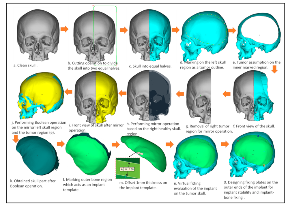
2.1. Creation of Artificial Defect
2.2. Design of Customized Implant
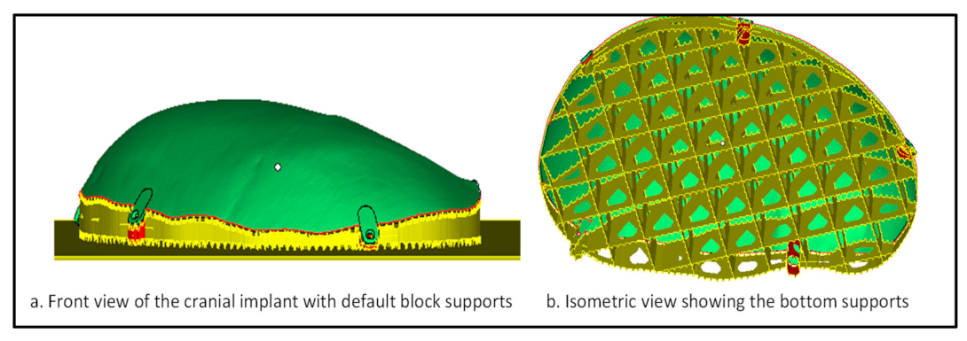
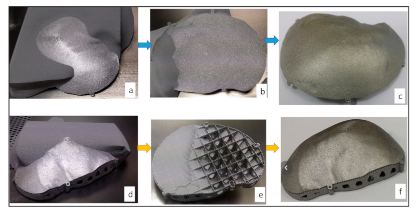
2.3. Fabrication
2.4. Evaluation
2.4.1. Implant Cost and Time Analysis
2.4.2. Accuracy Analysis
3. Results and Discussion
4. Conclusions
Author Contributions
Funding
Institutional Review Board Statement
Informed Consent Statement
Acknowledgments
Conflicts of Interest
References
- van de Vijfeijken, S.E.C.M.; Münker, T.J.A.G.; Spijker, R.; Karssemakers, L.H.E.; Vandertop, W.P.; Becking, A.G.; Ubbink, D.T. CranioSafe group autologous bone is inferior to alloplastic cranioplasties: Safety of autograft and allograft materials for cranioplasties, a systematic review. World Neurosurg. 2018, 117, 443–452. [Google Scholar] [CrossRef]
- Kim, B.; Hong, K.-S.; Park, K.-J.; Park, D.-H.; Chung, Y.-G.; Kang, S.-H. Customized cranioplasty implants using three-dimensional printers and polymethyl-methacrylate casting. J. Korean Neurosurg. Soc. 2012, 52, 541–546. [Google Scholar] [CrossRef]
- Unterhofer, C.; Wipplinger, C.; Verius, M.; Recheis, W.; Thomé, C.; Ortler, M. Reconstruction of large cranial defects with Poly-Methyl-Methacrylate (PMMA) using a rapid prototyping model and a new technique for intraoperative implant modeling. Neurol. Neurochir. Pol. 2017, 51, 214–220. [Google Scholar] [CrossRef]
- Chang, S.C.N.; Tobias, G.; Roy, A.K.; Vacanti, C.A.; Bonassar, L.J. Tissue engineering of autologous cartilage for craniofacial reconstruction by injection molding. Plast. Reconstr. Surg. 2003, 112, 793–799, discussion 800–801. [Google Scholar] [CrossRef]
- Brown, A.E.; Banks, P. Late extrusion of alloplastic orbital floor implants. Br. J. Oral Maxillofac. Surg. 1993, 31, 154–157. [Google Scholar] [CrossRef]
- Wolfaardt, J.F.; Coss, P. An impression and cast construction technique for implant-retained auricular prostheses. J. Prosthet. Dent. 1996, 75, 45–49. [Google Scholar] [CrossRef]
- Gibson, I.; Rosen, D.; Stucker, B. Additive Manufacturing Technologies: 3D Printing, Rapid Prototyping, and Direct Digital Manufacturing, 2nd ed.; Springer: New York, NY, USA, 2015; ISBN 978-1-4939-2112-6. [Google Scholar]
- Vandenbroucke, B.; Kruth, J.-P. Selective laser melting of biocompatible metals for rapid manufacturing of medical parts. Rapid Prototyp. J. 2007, 13, 196–203. [Google Scholar] [CrossRef]
- 3D Printing Industry (3DPI). Arcam Announces FDA Clearance of Implants Produced with Additive Manufacturing. Available online: http://www.arcam.com/arcam-announces-fda-clearance-of-implants-produced-with-additive-manufacturing (accessed on 31 March 2015).
- Chua, C.K.; Wong, C.H.; Yeong, W.Y. Standards, Quality Control, and Measurement Sciences in 3D Printing and Additive Manufacturing; Academic Press: Cambridge, MA, USA, 2017; ISBN 978-0-12-813490-0. [Google Scholar]
- Ameen, W.; Al-Ahmari, A.; Mohammed, M.K.; Abdulhameed, O.; Umer, U.; Moiduddin, K. Design, Finite Element Analysis (FEA), and fabrication of custom titanium alloy cranial implant using electron beam melting additive manufacturing. Adv. Produc. Engineer. Manag. 2018, 13, 267–278. [Google Scholar] [CrossRef] [Green Version]
- Al-Ahmari, A.; Nasr, E.A.; Moiduddin, K.; Anwar, S.; Kindi, M.A.; Kamrani, A. A comparative study on the customized design of mandibular reconstruction plates using finite element method. Adv. Mech. Eng. 2015, 7. [Google Scholar] [CrossRef] [Green Version]
- Ginestra, P.; Ferraro, R.M.; Zohar-Hauber, K.; Abeni, A.; Giliani, S.; Ceretti, E. Selective laser melting and electron beam melting of Ti6Al4V for orthopedic applications: A comparative study on the applied building direction. Materials 2020, 13, 5584. [Google Scholar] [CrossRef]
- Murr, L.E.; Gaytan, S.M.; Martinez, E.; Medina, F.; Wicker, R.B. Next Generation Orthopaedic Implants by Additive Manufacturing Using Electron Beam Melting. Available online: https://www.hindawi.com/journals/ijbm/2012/245727 (accessed on 3 February 2021).
- Kotzem, D.; Ohlmeyer, H.; Walther, F. Damage tolerance evaluation of a unit cell plane based on Electron Beam Powder Bed Fusion (E-PBF) manufactured Ti6Al4V alloy. Procedia Struct. Integr. 2020, 28, 11–18. [Google Scholar] [CrossRef]
- Cheng, B.; Chou, K. Geometric consideration of support structures in part overhang fabrications by electron beam additive manufacturing. Comput. Aided Des. 2015, 69. [Google Scholar] [CrossRef] [Green Version]
- Umer, U.; Ameen, W.; Abidi, M.H.; Moiduddin, K.; Alkhalefah, H.; Alkahtani, M.; Al-Ahmari, A. Modeling the effect of different support structures in electron beam melting of titanium alloy using finite element models. Metals 2019, 9, 806. [Google Scholar] [CrossRef] [Green Version]
- Tran, T.Q.; Chinnappan, A.; Lee, J.K.Y.; Loc, N.H.; Tran, L.T.; Wang, G.; Kumar, V.V.; Jayathilaka, W.A.D.M.; Ji, D.; Doddamani, M.; et al. 3D printing of highly pure copper. Metals 2019, 9, 756. [Google Scholar] [CrossRef] [Green Version]
- Shiomi, M.; Osakada, K.; Nakamura, K.; Yamashita, T.; Abe, F. Residual stress within metallic model made by selective laser melting process. CIRP Ann. 2004, 53, 195–198. [Google Scholar] [CrossRef]
- Hussein, A.; Hao, L.; Yan, C.; Everson, R.; Young, P. Advanced lattice support structures for metal additive manufacturing. J. Mater. Process. Technol. 2013, 213, 1019–1026. [Google Scholar] [CrossRef]
- Ameen, W.; Al-Ahmari, A.; Mohammed, M.; Mian, S. Manufacturability of overhanging holes using electron beam melting. Metals 2018, 8, 397. [Google Scholar] [CrossRef] [Green Version]
- Wang, D.; Mai, S.; Xiao, D.; Yang, Y. Surface quality of the curved overhanging structure manufactured from 316-L stainless steel by SLM. Int. J. Adv. Manuf. Technol. 2016, 86, 781–792. [Google Scholar] [CrossRef]
- Wang, D.; Yang, Y.; Zhang, M.; Lu, J.; Liu, R.; Xiao, D. Study on SLM fabrication of precision metal parts with overhanging structures. In Proceedings of the 2013 IEEE International Symposium on Assembly and Manufacturing (ISAM), Xi’an, China, 30 July–2 August 2013; pp. 222–225. [Google Scholar]
- Ford, S.; Despeisse, M. Additive manufacturing and sustainability: An exploratory study of the advantages and challenges. J. Clean. Prod. 2016, 137, 1573–1587. [Google Scholar] [CrossRef]
- Jiang, J.; Xu, X.; Stringer, J. Support structures for additive manufacturing: A review. J. Manuf. Mater. Process. 2018, 2, 64. [Google Scholar] [CrossRef] [Green Version]
- Morgan, D.; Agba, E.; Hill, C. Support structure development and initial results for metal powder bed fusion additive manufacturing. Procedia Manuf. 2017, 10, 819–830. [Google Scholar] [CrossRef]
- Samant, R.; Ranjan, R.; Mhapsekar, K.; Anand, S. Octree data structure for support accessibility and removal analysis in additive manufacturing. Addit. Manuf. 2018, 22, 618–633. [Google Scholar] [CrossRef]
- Jhabvala, J.; Boillat, E.; André, C.; Glardon, R. An innovative method to build support structures with a pulsed laser in the selective laser melting process. Int. J. Adv. Manuf. Technol. 2012, 59, 137–142. [Google Scholar] [CrossRef] [Green Version]
- Yan, C.; Hao, L.; Hussein, A.; Raymont, D. Evaluations of cellular lattice structures manufactured using selective laser melting. Int. J. Mach. Tools Manuf. 2012, 62, 32–38. [Google Scholar] [CrossRef]
- Park, S.; Rosen, D.; Duty, C. Comparing mechanical and geometrical properties of lattice structure fabricated using electron beam melting. In Proceedings of the 2014 Annual International Solid Freeform Fabrication Symposium—An Additive Manufacturing Conference, Austin, TX, USA, 6 August 2014; Volume 1, pp. 1359–1370. [Google Scholar]
- Li, Z.; Zhang, D.Z.; Dong, P.; Kucukkoc, I. A lightweight and support-free design method for selective laser melting. Int. J. Adv. Manuf. Technol. 2017, 90, 2943–2953. [Google Scholar] [CrossRef] [Green Version]
- Langelaar, M. Topology optimization of 3D self-supporting structures for additive manufacturing. Addit. Manuf. 2016, 12, 60–70. [Google Scholar] [CrossRef] [Green Version]
- Calignano, F. Design optimization of supports for overhanging structures in aluminum and titanium alloys by selective laser melting. Mater. Des. 2014, 64, 203–213. [Google Scholar] [CrossRef]
- Ruffo, M.; Tuck, C.; Hague, R. Cost estimation for rapid manufacturing-laser sintering production for low to medium volumes. Proc. Inst. Mech. Eng. Part B 2006, 220, 1417–1427. [Google Scholar] [CrossRef] [Green Version]
- Hopkinson, N.; Dicknes, P. Analysis of rapid manufacturing—Using layer manufacturing processes for production. Proc. Inst. Mech. Eng. Part C 2003, 217, 31–39. [Google Scholar] [CrossRef] [Green Version]
- Syam, W.; Al-Ahmari, A.; Mannan, M.; Al-Shehri, H.; Al-Wazzan, K. Metallurgical, accuracy and cost analysis of Ti6Al4V dental coping fabricated by electron beam melting process. In Proceedings of the 5th International Conference on Advanced Research in Virtual and Rapid Prototyping, Leiria, Portugal, 28 September–1 October 2011; ISBN 978-0-415-68418-7. [Google Scholar]
- Lindemann, C.; Jahnke, U.; Habdank, M.; Koch, R. Analyzing product lifecycle costs for a better understanding of cost drivers in additive manufacturing. In Proceedings of the 23th Annual International Solid Freeform Fabrication Symposium—An Additive Manufacturing Conference, Austin, TX, USA, 6–8 August 2012. [Google Scholar]
- Baumers, M.; Dickens, P.; Tuck, C.; Hague, R. The cost of additive manufacturing: Machine productivity, economies of scale and technology-push. Technol. Forecast. Soc. Chang. 2016, 102, 193–201. [Google Scholar] [CrossRef]
- Priarone, P.C.; Robiglio, M.; Ingarao, G.; Settineri, L. Assessment of cost and energy requirements of Electron Beam Melting (EBM) and machining processes. In International Conference on Sustainable Design and Manufacturing, Bologna, Italy, 26–28 April 2017; Campana, G., Howlett, R.J., Setchi, R., Cimatti, B., Eds.; Smart Innovation, Systems and Technologies; Springer: Cham, Switzerland, 2017; Volume 68, pp. 723–735. ISBN 978-3-319-57077-8. [Google Scholar]
- Choi, J.-Y.; Choi, J.-H.; Kim, N.-K.; Kim, Y.; Lee, J.-K.; Kim, M.-K.; Lee, J.-H.; Kim, M.-J. Analysis of errors in medical rapid prototyping models. Int. J. Oral Maxillofac. Surg. 2002, 31, 23–32. [Google Scholar] [CrossRef]
- Mostafa Elkatatny, A.A.A.; Eldabaa, K.A. Cranioplasty: A new perspective. Open Access Maced. J. Med. Sci. 2019, 7, 2093–2101. [Google Scholar] [CrossRef] [PubMed] [Green Version]
- Höhne, J.; Brawanski, A.; Gassner, H.; Schebesch, K.-M. Feasibility of the custom-made titanium cranioplasty CRANIOTOP®. Surg. Neurol. Int. 2013, 4, 88. [Google Scholar] [CrossRef] [PubMed]
- Brown, D.A.; Wijdicks, E.F.M. Decompressive craniectomy in acute brain injury. Handb. Clin. Neurol. 2017, 140, 299–318. [Google Scholar] [CrossRef] [PubMed]
- Toth, B.A.; Ellis, D.S.; Stewart, W.B.; Jeffrey, L.; Marsh, D.; Vannier, M.W. Computer-designed prostheses for orbitocranial reconstruction. Plast. Reconstr. Surg. 1988, 81, 323–3241. [Google Scholar] [CrossRef]
- Joffe, J.M.; McDermott, P.J.; Linney, A.D.; Mosse, C.A.; Harris, M. Computer-generated titanium cranioplasty: Report of a new technique for repairing skull defects. Br. J. Neurosurg. 1992, 6, 343–350. [Google Scholar] [CrossRef]
- Webb, P.A. A Review of Rapid Prototyping (RP) techniques in the medical and biomedical sector. J. Med. Eng. Technol. 2000, 24, 149–153. [Google Scholar] [CrossRef]
- Moreira-Gonzalez, A.; Jackson, I.T.; Miyawaki, T.; Barakat, K.; DiNick, V. Clinical outcome in cranioplasty: Critical review in long-term follow-up. J. Craniofac. Surg. 2003, 14, 144–153. [Google Scholar] [CrossRef]
- Maravelakis, E.; David, K.; Antoniadis, A.; Manios, A.; Bilalis, N.; Papaharilaou, Y. Reverse engineering techniques for cranioplasty: A case study. J. Med. Eng. Technol. 2008, 32, 115–121. [Google Scholar] [CrossRef]
- Moiduddin, K.; Hammad Mian, S.; Umer, U.; Ahmed, N.; Alkhalefah, H.; Ameen, W. Reconstruction of complex zygomatic bone defects using mirroring coupled with EBM fabrication of titanium implant. Metals 2019, 9, 1250. [Google Scholar] [CrossRef] [Green Version]
- Alsing, L.; Storm, S.J. Sustainability of Additive Manufacturing—Electron Beam Melting of IN718. Ph.D. Thesis, University West, Trollhättan, Sweden, 2019. [Google Scholar]
- Arcam A2 Setting the Standard for Additive Manufacturing. Available online: http://www.arcam.com/wp-content/uploads/Arcam-A2.pdf (accessed on 12 July 2019).


| Influencing Factors | Description | Values | Estimation |
|---|---|---|---|
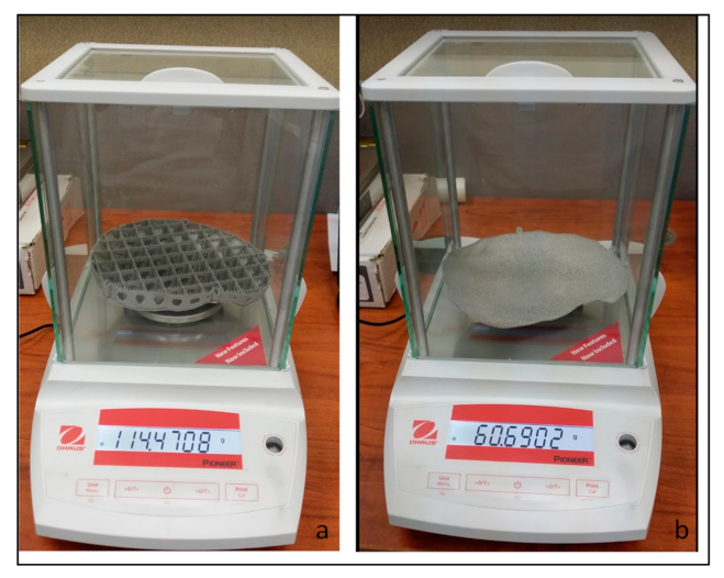
| Material consumption (grams) MConsumption | Weight of implant with supports | 114.47 g | |
| Weight of Implant without supports | 60.69 g | ||
| Material wastage including support structures [50] | 10% of built mass | ||
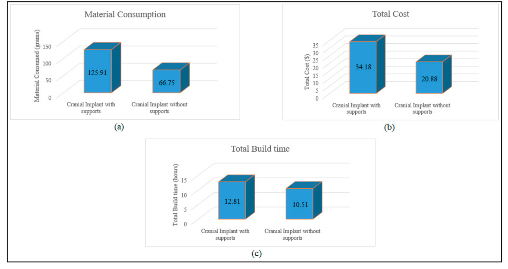
| Mconsumption (Material consumed for cranial implant with supports) | 125.91 g | Total mass of EBM built implant = (Implant mass + 10% material wastage of built mass) = 114.47 + 11.44 | |
| Mconsumption (Material consumed for cranial implant without supports) | 66.75 g | 60.69 + 6.06 | |
| Material cost (per gram) | CRaw (Ti6Al4V ELI cost price) | $0.22/g | =$220/kg |
| (Mconsumption × CRaw) Supports | Implant with supports | $27.70 | (125.91 g × $0.22/g) |
| ((Mconsumption × CRaw) Without supports | Implant without supports | $14.68 | (66.75 g × $0.22/g) |
| TFabrication (cranial implants with supports) | Time to obtain desired vacuum level | 0:3 hh:mm | |
| Time to heat start plate | 0:45 hh:mm | ||
| EBM cool down time | 4:00 hh:mm | ||
| Build time for cranial implant with supports | 5:39 hh:mm | ||
| TFabrication Time for completion of cranial build with supports | 10.9 h | Time for desired vacuum level + heating start plate + EBM cool down time + part build time (0:30 + 0:45 + 4:00 + 5:39) = 10:54 hh:mm = 10.9 h | |
| TFabrication (cranial implants without supports) | Build time for cranial implant without supports | 5.11 hh:mm | |
| TFabrication Time for completion of cranial build without supports | 10.43 h | Time for desired vacuum level + heating start plate + EBM cool down time + part build time (0:30 + 0:45 + 4:00 + 5:11) = 10:26 hh:mm = 10.43 h | |
| TFabrication (with supports) | Implant with support | 10.90 h | |
| TFabrication (without supports) | Implant without support | 10.43 h | |
| EBM energy consumption (KW) for Implant fabrication EBuild | EBM Power supply | 7 KW [51] | |
| EBM Electricity cost (Per hour) PEnergy | PEnergy (EBM energy consumption cost) | $0.085/KWh | Electricity tariff = SAR 0.32/KWh(https://www.se.com.sa/en-us/customers/Pages/TariffRates.aspx (accessed on 18 August 2020)) Conversion of SAR to $ = $0.085/KWh |
| EBuild × TFabrication (with supports) × PEnergy | Cranial implant with supports | $6.48 | =(EBM power consumption x EBM build time for cranial implant with supports x EBM energy consumption cost) = 7 KW × 10.9 hours’ × $0.085/KWh |
| EBuild × T Fabrication (without supports) × PEnergy | Cranial implant without supports | $6.20 | =7 KW × 10.43 h × $0.085/KWh |
| Total Cost for building implant | Implant with supports | $34.18 | (material cost + Energy consumption cost) = $27.70 + $6.48 |
| Implant without support | $20.88 | =$14.68 + $6.20 | |
| Percentage Difference in cost | 39% | =(13.3/34.18) × 100 |
| Factors | Description | Values | Estimation |
|---|---|---|---|
| Build Time (Hours) | BHours (Build Hours for Cranial Implant with Supports) | 10:54 hh:mm | Time Taken for the Fabrication of Cranial Implant with Supports- (0:3 + 0:45 + 4:00 + 5:39) = 10:54 hh:mm |
| BHours (Build Hours for Cranial Implant without Supports) | 10:26 hh:mm | =(0:3 + 0:45 + 4:00 + 5:11) =10:26 hh:mm | |
| EBM Post-Processing Time (Hours) PPTime | Post processing time for implant with supports | 1:55 hh:mm | Post processing time includes the removal of supports + removal of semi-centered powder (1:45 + 0:10) hh:mm |
| Post processing time for implant without supports | 0:05 hh:mm | Removal of semi-centered powder. | |
| Total Build time for Cranial implant | Total build time for cranial implant with support after post-processing | 12:49 hh:mm | Total Build time = (fabrication time + post-processing time) (10:54 + 1:55) hh:mm =12:49 hh:mm = 12.81 h |
| Total build time for cranial implant without support after post-processing | 10:31 hh:mm | (10:26 + 0:05) hh:mm | |
| Percentage difference in build time | 18% | =(12:49–10:31) =2:18 hh:mm (2.30 h) =(2.30/12.81) × 100 |
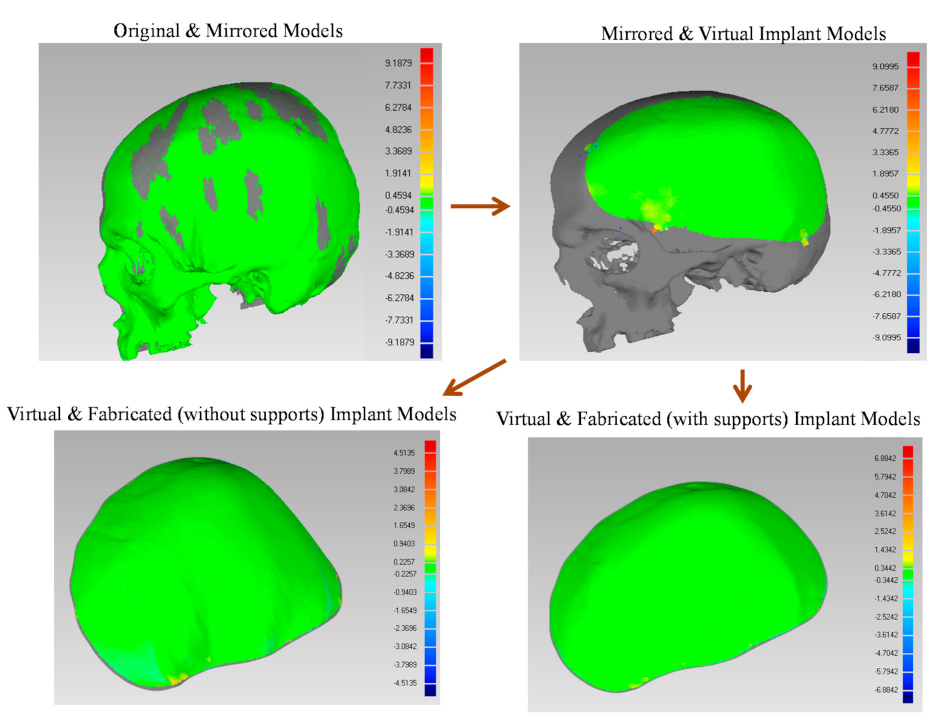
| Models Combination | Notations | Deviation (mm) |
|---|---|---|
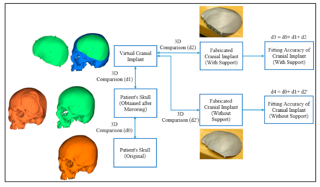
| Original (Reference) and Mirroring (Test) | d0 | 0.1458 |
| Mirroring (Reference) and Virtual Implant (Test) | d1 | 0.0182 |
| Virtual Implant (Reference) and Fabricated Implant with Supports (Test) | d2 | 0.0904 |
| d3 | 0.2544 | |
| Virtual Implant (Reference) and Fabricated Implant without Supports (Test) | d2′ | 0.0973 |
| d4 | 0.2613 |
Publisher’s Note: MDPI stays neutral with regard to jurisdictional claims in published maps and institutional affiliations. |
© 2021 by the authors. Licensee MDPI, Basel, Switzerland. This article is an open access article distributed under the terms and conditions of the Creative Commons Attribution (CC BY) license (http://creativecommons.org/licenses/by/4.0/).
Share and Cite
Moiduddin, K.; Mian, S.H.; Ameen, W.; Alkhalefah, H.; Sayeed, A. Feasibility Study of the Cranial Implant Fabricated without Supports in Electron Beam Melting. Metals 2021, 11, 496. https://doi.org/10.3390/met11030496
Moiduddin K, Mian SH, Ameen W, Alkhalefah H, Sayeed A. Feasibility Study of the Cranial Implant Fabricated without Supports in Electron Beam Melting. Metals. 2021; 11(3):496. https://doi.org/10.3390/met11030496
Chicago/Turabian StyleMoiduddin, Khaja, Syed Hammad Mian, Wadea Ameen, Hisham Alkhalefah, and Abdul Sayeed. 2021. "Feasibility Study of the Cranial Implant Fabricated without Supports in Electron Beam Melting" Metals 11, no. 3: 496. https://doi.org/10.3390/met11030496