Article

Study on Inclusions Distribution and Cyclic Fatigue Performance of Gear Steel 18CrNiMo7-6 Forging

1
State Key Laboratory of Advanced Metallurgy, University of Science and Technology Beijing, Beijing 100083, China
2
CISDI Engineering Co. Ltd., Chongqing 400013, China
*
Author to whom correspondence should be addressed.
Metals 2020, 10(2), 201; https://doi.org/10.3390/met10020201
Submission received: 12 December 2019 / Revised: 24 January 2020 / Accepted: 25 January 2020 / Published: 31 January 2020
(This article belongs to the Special Issue 10th Anniversary of Metals: Metallurgy and Metal Technology)

Abstract

:
The three-dimensional morphologies of inclusions in gear steel 18CrNiMo7-6 forging were investigated by a non-destructive extraction method, and the cleanliness of radial positions was analyzed, mainly including the variation of total oxygen content and the distribution of size and quantity of inclusions. In addition, fatigue performance was tested using an ultrasonic fatigue machine to investigate the fatigue characteristics of the steel. The results show that the quantity density of inclusions per unit volume in gear steel 18CrNiMo7-6 decreases exponentially with increasing size, oxide inclusions with a size less than 8 μm account for more than 90%, while sulfide inclusions account for more than 85%. The average value of the oxygen content can reflect the level of inclusions that were evenly distributed in the molten steel, and the accumulative total oxygen content increases significantly with increasing inclusion size. The fatigue specimen failed after the stress exceeded the critical value, and fatigue failure hardly occurred when the stress was below the critical value. Meanwhile, large-sized nondeformable inclusions such as Al2O3-CaO in gear steel 18CrNiMo7-6 are closely related to fatigue failure. It is recommended that the area from the center to the 1/2 radius with low cleanliness should be avoided, while the area from the 3/4 radius to the edge with high cleanliness should be selected during the machining of the gear.

1. Introduction

As a necessary transmission part of mechanical equipment, different kinds of high-alloy gears have been widely applied and popularized in industrial production to meet the requirements of aerospace, metallurgical manufacturing, automobile production, mining, lifting transportation and building materials machinery, etc. [1,2]. Among them, the application of 18CrNiMo7-6 according to the standard of DIN (German Institute for Standardization) in Germany has become increasingly widespread with the expansion of high-alloy gear steel production, and the predecessor of this steel is 17CrNiMo6 gear steel [2].
Carburizing gear steel 18CrNiMo7-6 is a surface-hardened steel with high strength, high toughness and high hardenability, which is widely used in mining, transportation, locomotive traction, lifting and internal power, and other industrial fields [3]. JFE steel corporation has developed a new carburizing steel that realizes an intermediate heat treatment-free process (omission of annealing before cold forging and normalizing before carburizing) in the manufacture of carburized gear parts, which makes it possible to reduce the cost and improve the fatigue life of gear parts [4]. The mechanical properties in relation to fracture toughness are often governed by the independent or conjoint influences of the following [5,6]: (a) chemical composition, (b) steel cleanness including inclusions and harmful elements in the matrix, (c) processing history and development of intrinsic microstructural features, (d) service conditions and circumstances of the components including loading-rate, working temperature and the presence of constraints at the crack tip. High surface quality was the essential condition to meet the requirement of harsh working conditions of the gear steel, so it is necessary to control the steel cleanliness and inclusions characterization, including morphologies, size, number and distribution, for guaranteeing the fatigue property of the steel [7,8,9,10]. An et al. [11] studied the inclusions evolution of gear steel in the refining process, and discovered the formation mechanism of oxide-sulfide duplex inclusion. Dong et al. [12,13] found that the large inclusions in gear steel are mainly external during the refining process. Nordin et al. [14] summarized that there were three main factors from shot peening that influence the fatigue life of gear steel: residual stresses, microstructure and surface roughness. However, previous studies did not cover the in-depth study of the relationship between inclusions distribution and the fatigue property of final products of gear steel. It is necessary to discover an optimum method to evaluate the fatigue life under various manufacturing conditions because of the long duration of fatigue life of high-quality steel. Recently, the ultra-sonic method has been one of the available methods for the testing of cracks and fatigue life of steel.
In this paper, gear steel 18CrNiMo7-6 forging is studied. The three-dimensional morphologies of inclusions in the gear steel were determined by the non-destructive extraction method of inclusions, and the variation of total oxygen content as well as the size, quantity and composition of inclusions in different radial positions were also investigated to clarify the distribution of the cleanliness of the gear steel and the area where the inclusions accumulate. In addition, fatigue tests were also carried out using an ultrasonic fatigue testing machine to investigate the fatigue characteristics of the steel. This provides theoretical guidance for avoiding areas of poor cleanliness in follow-up processing, thereby laying the foundation for further improving the quality of gears [15].

2. Experimental Materials and Methods

2.1. Experimental Materials

The smelting technological process of gear steel 18CrNiMo7-6 is as follows: EAF→LF→VD→Ingot cast. The ingot was forged into a piece for the gear process. The following steps are required for the forge piece to be processed into a gear: normalizing→rough turning→quenching and tempering→finish turning→cutting teeth→carburizing, quenching and tempering→making spline→gear grinding. A forge piece with a diameter of 280 mm was prepared before cutting teeth for the experiment. The chemical composition of the steel is listed in Table 1.
Different types of samples as described in Figure 1 were prepared for total oxygen testing, inclusions extraction, inclusions quantitative analysis and cyclic fatigue performance evaluation. Fourteen rod-like specimens with sizes of ϕ10 mm × 80 mm were machined along the edge of the forging ingot for the fatigue performance test. Cubic specimens with sizes of 15 mm × 15 mm × 15 mm were machined in the locations of center, 1/2 radius, 3/4 radius, and outer edge of the forge piece for inclusions quantitative analysis by automatic scanning technology. Rod-like specimens for total oxygen testing were cut from the center, 1/4 radius, 1/2 radius, 3/4 radius and outer edge of the forge piece.

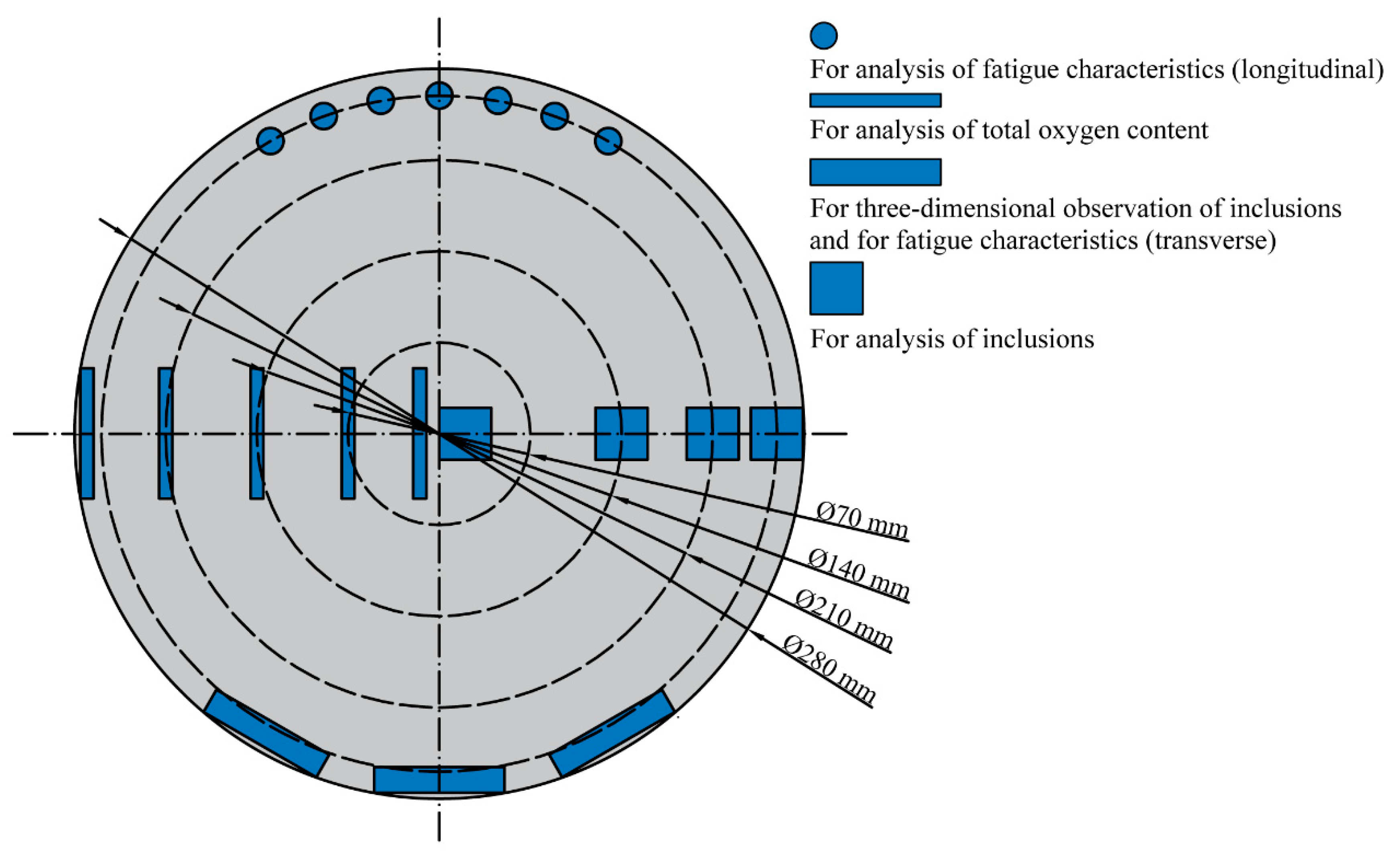
2.2. Experimental Methods

The total oxygen in radial positions of the gear steel was analyzed using the infrared absorption method. Inclusions were extracted from the steel matrix using a non-destructive method with aqueous solution (deionized water + potassium chloride + citric acid) and collected on the conductive adhesive after separating with a filter membrane to observe the three-dimensional morphologies of the inclusions under a scanning electron microscope [16]. The Oxford INCA System (EVO18, Zeiss, Oberkochen, Germany) was adopted to analyze the sizes, shapes and chemical compositions of inclusions on a scanning area of 53.5 mm2. Cycle fatigue performance was tested using an ultrasonic fatigue system (CSPL-20, Chengdu MCT Technology Co. Ltd., Chengdu, China) with 20 KHz frequency under fully reversed tension-compression (R = −1) loading condition. The stability diagram of the Fe-Si-Al-Mg-O system inclusions was calculated in liquid steel at 1600 °C by using FactSage 7.2 (The Integrated Thermodynamic Databank System, GTT-Technologies, Herzogenrath, Germany).

3. Results and Discussion

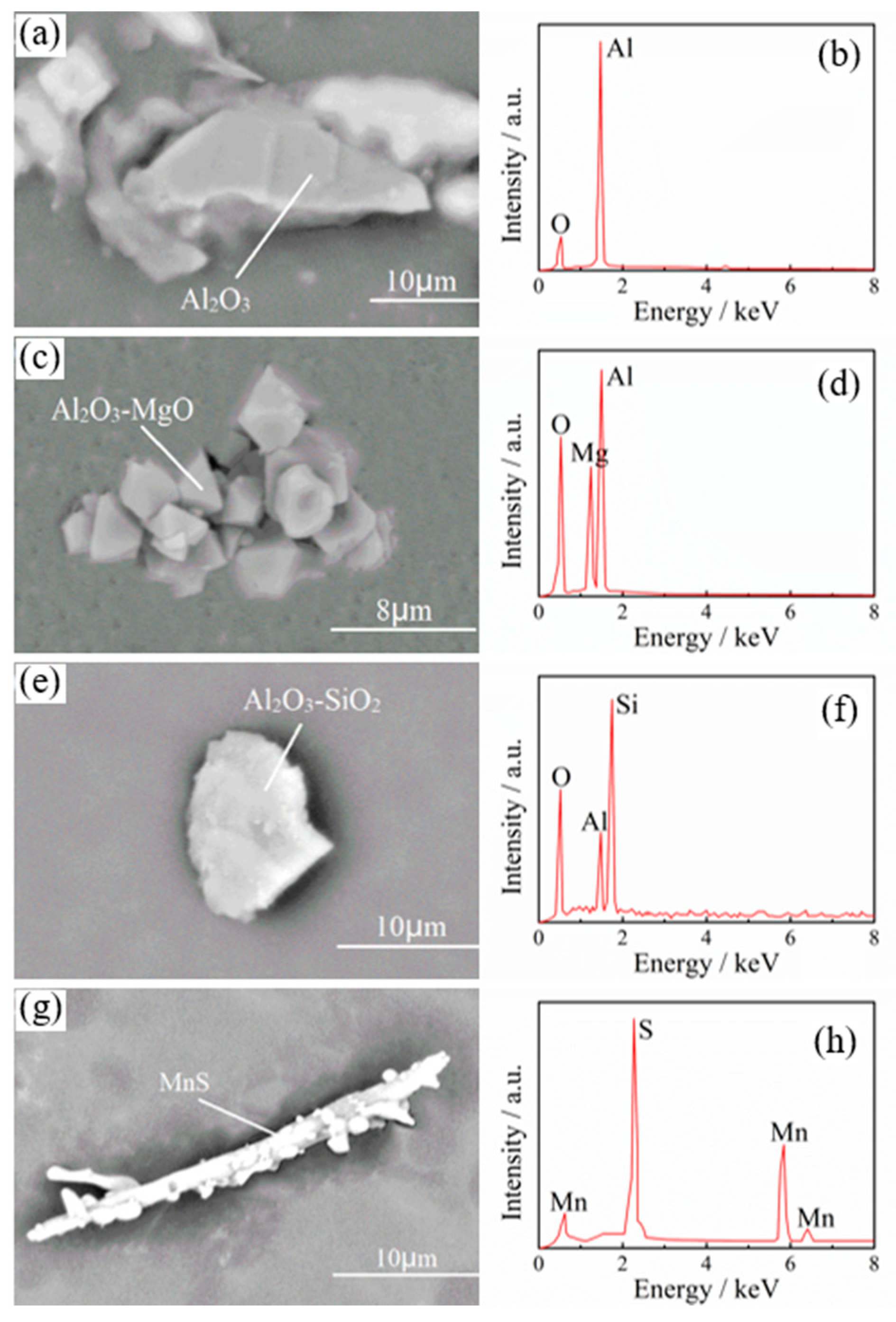
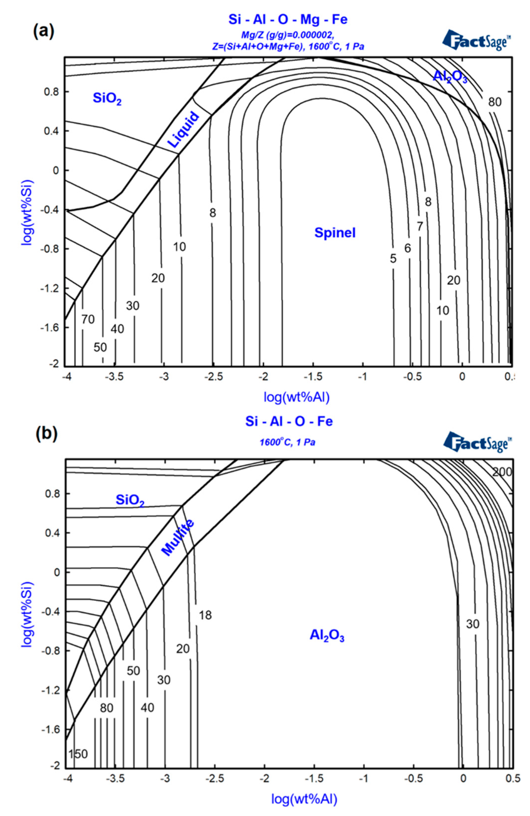
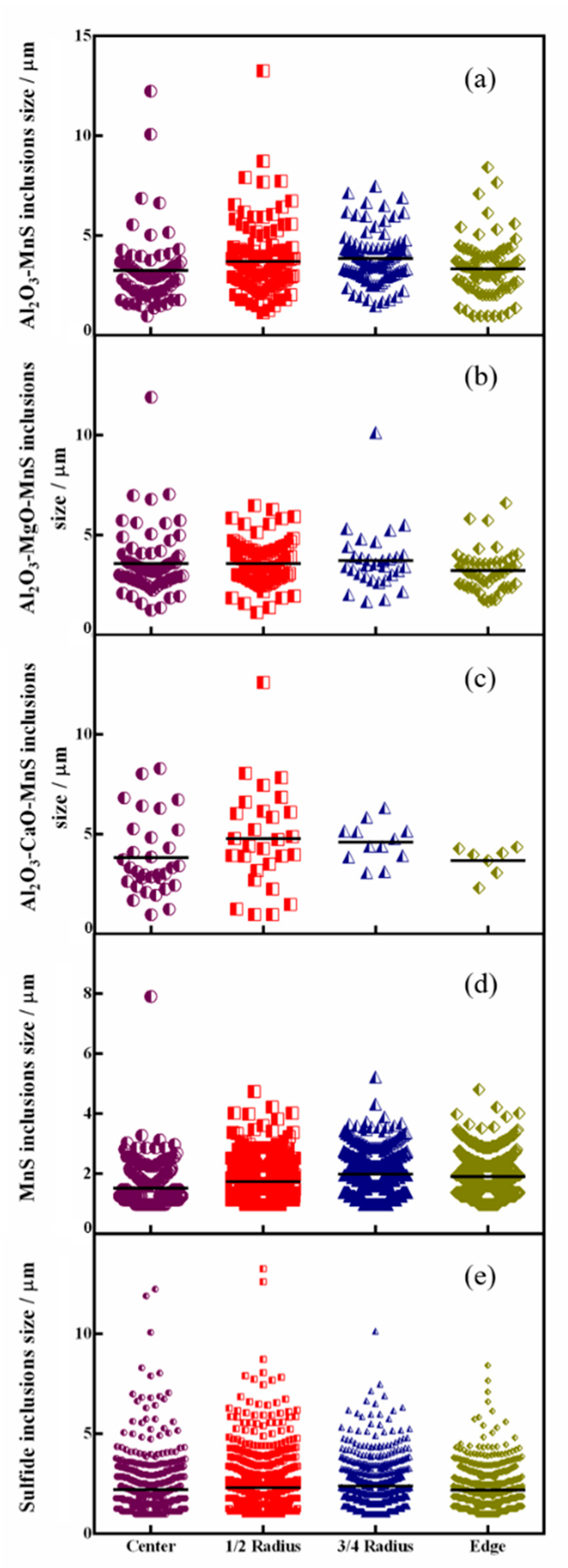
3.1. Morphological Characteristics of Inclusions in the Gear Steel

As showed in Figure 2, four different types of inclusions, namely, MnS, Al2O3, Al2O3-MgO, and Al2O3-SiO2, are found on the forging cross-section after the treatment of non-destructive extraction.
The morphology of Al2O3 is mostly massive, with a diameter of 5–15 μm, and it is a common deoxidization product in the steelmaking process with a large quantity. The Al2O3-MgO spinel is similar to the Al2O3 inclusions with small clusters, and both of them are harmful to the fatigue life of steel due to the high hardness and low deformability [17,18,19]. Additionally, some spherical and spheroidal silicates, which possessed relatively low hardness and good formability compared with the Al2O3 and spinel, were also found.
MnS inclusions in the steel matrix are mostly elongated or spindle-shaped after the rolling process due to their good plasticity. It has been pointed out that spindle MnS inclusions are beneficial to the mechanical properties and free-cutting properties of steel, but have almost no effect on the quality of steel [20].
In Figure 3, inclusion stability diagrams of the Fe-Si-Mg-O system (a) and the Fe-Si -O system (b) at 1600 °C were calculated. It can be seen that Al2O3-MgO (spinel) and Al2O3 can be formed and exist stably in molten steel after the deoxidization. The formation time of sulfide inclusions is later than that of oxide inclusions, most of which are formed during the solidification of molten steel. Therefore, the oxide inclusions can easily provide nucleation conditions for the formation of sulfide inclusions. It has been pointed out that the MnS inclusion can almost precipitate [21] on any kind of oxide when w(S) is more than 0.01%. The content of S in the forging of gear steel 18CrNiMo7-6 is more than 0.01%, resulting in complex inclusions with oxide inclusions as the core and MnS forming wraps around the periphery. Due to the better plasticity and softer texture of MnS inclusions, the harmful effects of Al2O3, Al2O3-MgO, silicate and other oxide inclusions on the steel matrix can be reduced to a certain extent. Moreover, there is a small amount of high-melting CaS inclusions in gear steel 18CrNiMo7-6. These inclusions are also easily deformed during rolling, and the three-dimensional morphology is basically in a regular strip shape. The formation of such inclusions is caused by excessive calcium content during the refining process [22,23].

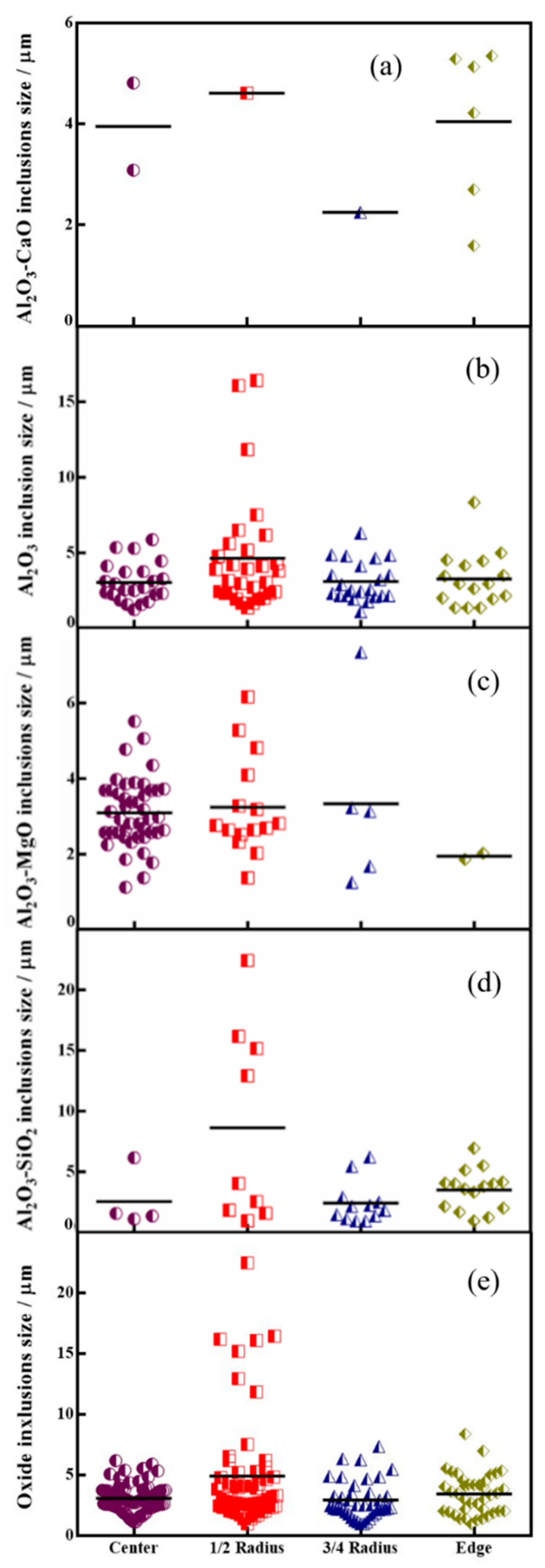
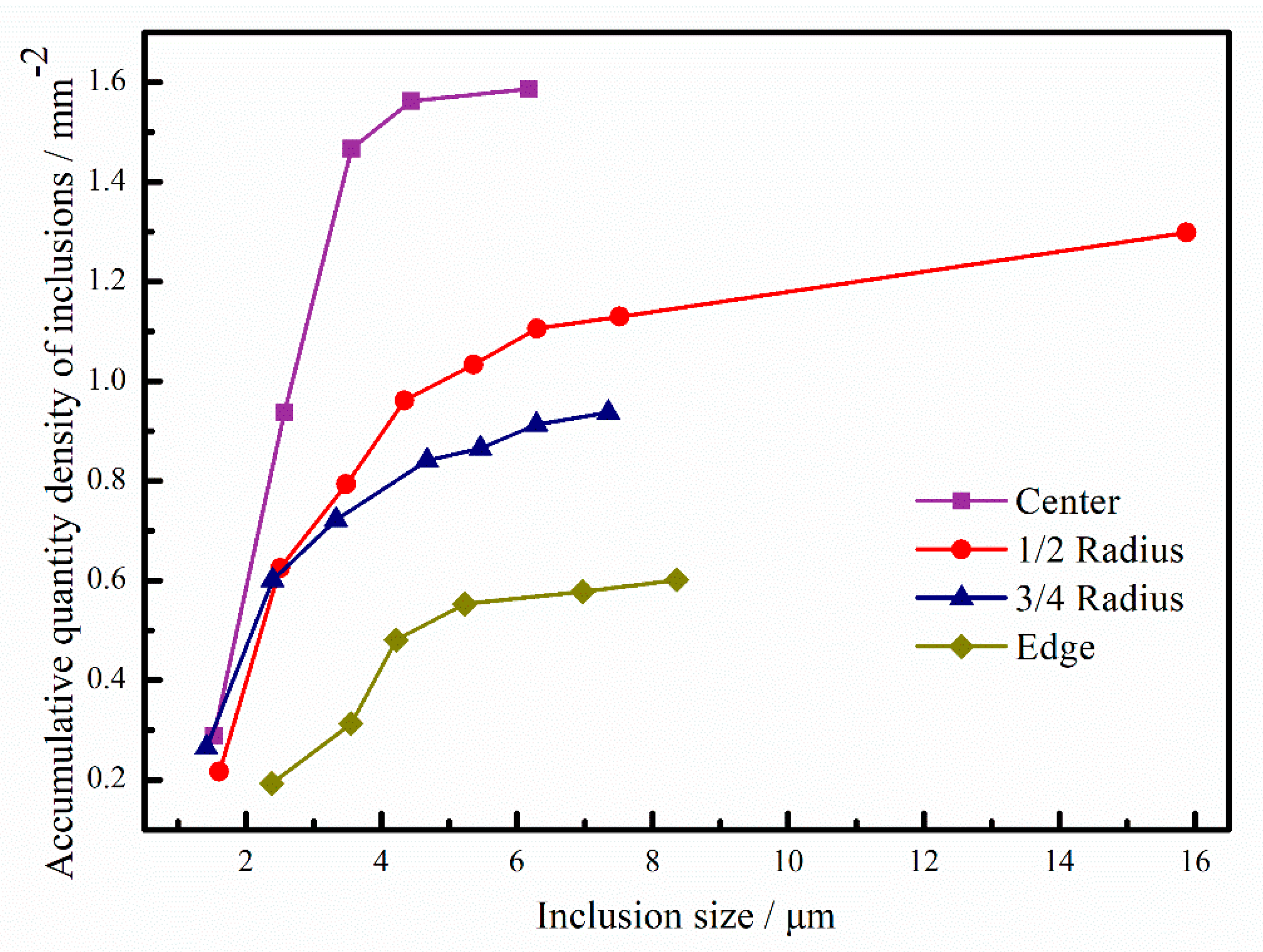
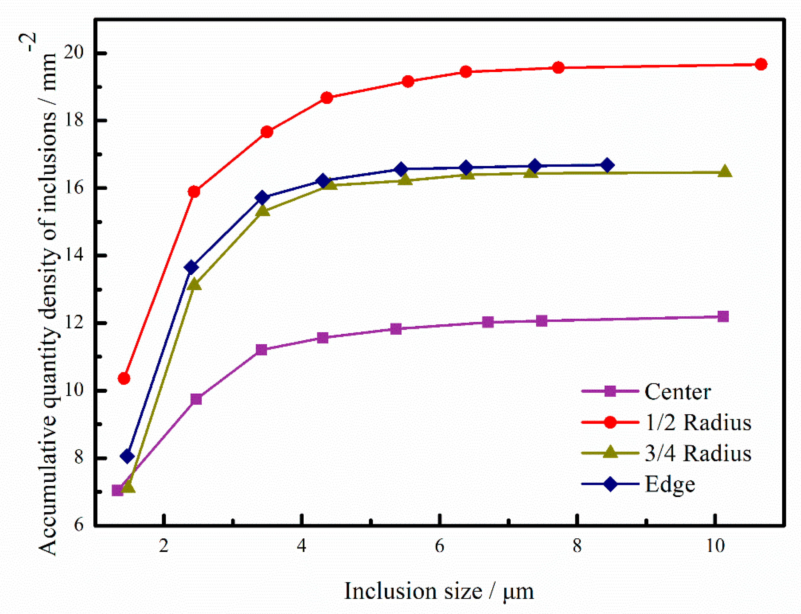
3.2. Distribution of Inclusions in Radial Directions

The quantitative distribution of the main inclusions in the center, 1/2 radius, 3/4 radius and edge of the forging were analyzed using the Oxford INCA System. Four different types of oxide inclusions, mainly including Al2O3-CaO, Al2O3, Al2O3-MgO and silicates, existed in the steel matrix. Figure 4a shows the distribution of Al2O3-CaO inclusions. The total amount of such inclusions is small, but a large proportion of such inclusions are distributed on the edge of the forge piece, which is very damaging for the working condition of the gear because this area is very close to the service face of the gear. Figure 4b shows the size distribution of Al2O3 inclusions. The Al2O3 inclusions with sizes of 2–4 μm occupy the largest proportion of 50.7%. With increasing size, the proportion of inclusions decreases gradually. The largest proportions of inclusions with sizes below 4 μm from the center to the edge reach 78.3%, 60.0%, 72.7% and 68.8%, respectively. Large-sized inclusions above 10 μm only appear at the location of the 1/2 radius and account for 10% of the total. The sizes of Al2O3-MgO inclusions are all below 10 μm, and the number of 2–4 μm reaches 59.6%. The largest proportions of inclusions with sizes below 4 μm from the center to the edge reach 100.0%, 90.9%, 73.3%, and 80.0%, respectively. Figure 4d shows the size distribution of silicate inclusions, and large silicate inclusions with sizes above 10 μm appear at the location of the 1/2 radius, accounting for 44.4% of the total silicate inclusions.
The relationship between the accumulative oxide density and the size in per unit volume is shown in Figure 5, indicating that the quantity of inclusions with a size less than 8 μm accounts for more than 90%. With increasing inclusion size, the quantity density tends to decrease. The quantity density of Al2O3 inclusions along the radius shows little change. The quantity densities of Al2O3-MgO and silicate inclusions reach the highest at 0.82/mm2 and 0.36/mm2, respectively.
Figure 6 shows the size distribution of sulfide inclusions. The largest proportion of inclusions with sizes below 2 μm reaches 50.5%. From the center to the edge, the number of sulfide inclusions decreases gradually, and the average sizes increase slightly, which is due to the segregation of sulfur during the solidification.
Figure 7 shows the distribution of sulfide inclusions per unit volume. It is found that the quantity of inclusions decreases exponentially with increasing size. As can be seen from Figure 6, the quantity of sulfide inclusions with a size less than 8 μm accounts for more than 85%.
The machinability of gear steel is caused by a large amount of sulfide inclusions in the steel. Compared with oxide inclusions, the size distribution of sulfide inclusions is similar to the former, and their range is wider. As for the distribution of inclusions, the amount of sulfide inclusions in each position is much larger than that of oxide inclusions. Owing to the fact that the sulfide inclusions contained some composite inclusions of oxides and sulfides, it is well explained that the cumulative total oxygen content of the oxide inclusions is significantly lower than the total oxygen content measured by the infrared absorption method.
Based on the above analysis, inclusions with sizes above 10 μm mainly exist in a band area from the center to the 1/2 radius. Actually, the band with large sizes of inclusions is far from the working face of the gear, and that is also good for the fatigue life of the gear. So, it is critical to control both the sizes and distribution of inclusions on the section of the forging [24].
In summary, considering the distribution of total oxygen content, inclusion quantity distribution and size distribution of gear steel 18CrNiMo7-6 forging, the area from the 3/4 radius to the edge with high cleanliness is more reasonable to be selected for the machining of the gear face.

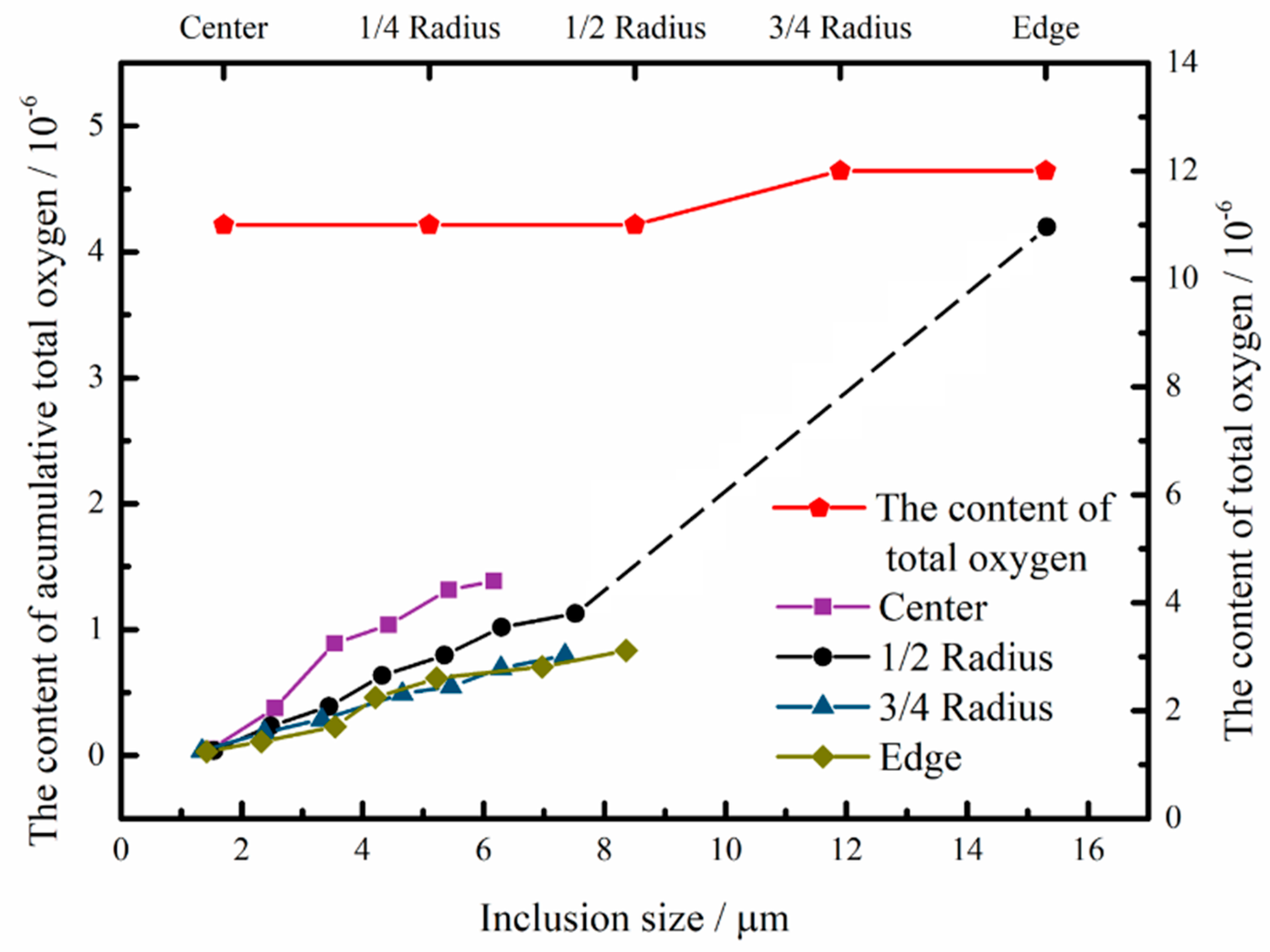
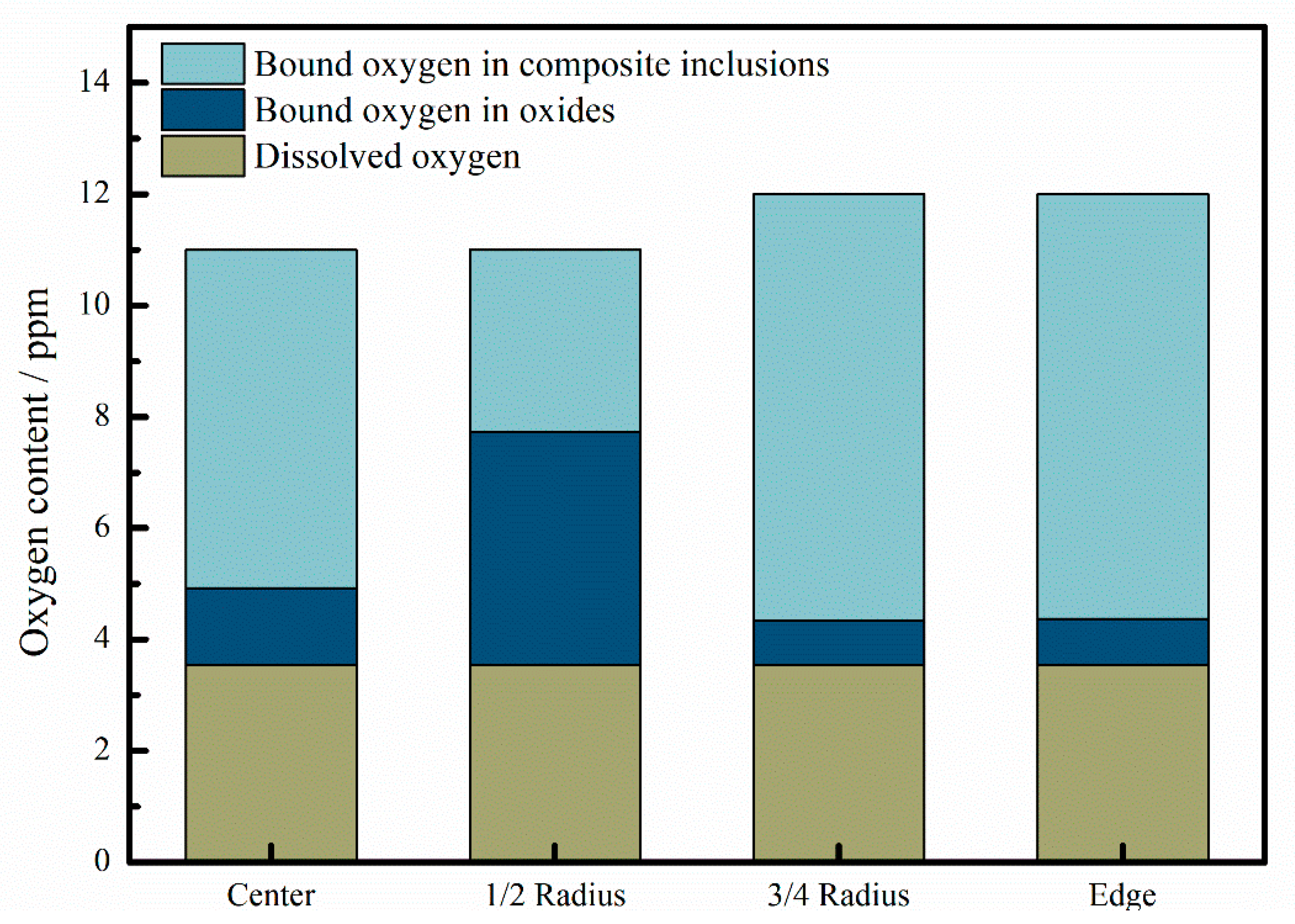
3.3. Relationship between Total Oxygen and Inclusions

The accumulative oxygen content in oxide inclusions with different sizes can be calculated by Equations (1)–(4) [25,26,27] to estimate the contributions of oxides inclusions to the total oxygen in the steel. In these equations, DeHoff’s formulas are expressed by Equations (1) and (2), the volume fraction of oxides can be obtained by Equation (3), and the oxygen content in oxide inclusions is described by Equation (4).
N v = 2 π · N a d ¯ ,
1 d ¯ = 1 n 1 d i ,
V = π 6 d ¯ 3 · N v ,
[ O ] ox =   ( ρ ox ρ Fe ) · V · ( O ) ox ,
where NV is the number of oxide inclusions per unit volume in the specimen, in m−3; Na is the number density of oxide inclusions per unit area in the specimen, in m−2; di is the apparent particle size of the i-th oxide inclusions among n oxides, in m; d ¯ is the harmonic mean of oxide inclusions’ particle size, in m; V is the volume fraction of oxide inclusions; [O]ox is the oxygen content in oxide inclusions in the steel; ρox is the density of oxide inclusions, in kg∙m−3; ρFe is the density of the steel, in kg∙m−3; (O)ox is the oxygen content of oxide inclusions.
Figure 8 shows the relationship between oxide sizes and the accumulative oxygen in oxides per unit volume. It was reported by [21] that the proportion of bound oxygen in oxides with diameters smaller than 5 μm exceeded 80% of the total oxygen in Al-killed steel. Under the present results, the oxygen in oxide inclusions with sizes below 8 μm occupies less than 13% of the total oxygen in the steel.
The accumulative total oxygen content increases with increasing inclusion size when the size is less than 8 μm. The quantity of inclusions with a size less than 8 μm accounts for more than 90%, making a vital contribution to total oxygen. Except for the sharp increase in the oxygen content due to the large-sized inclusions appearing at the 1/2 radius, the oxygen content increases steadily as the size of inclusions increases at other positions, and the cumulative oxygen content is stabilized at a fixed value.
In Al-deoxidization liquid steel, the dissolved oxygen content depends on the Al content. The reaction between [Al] and [O] can be expressed by
2[Al] + 3[O] = Al2O3(s)
GѲ = −1218799 + 394.13T
Considering fAl = fO = 1, and when T = 1873 K, there are
[ % A l ] [ % O ] 1 . 5 =   2.00   ×   10 7
In this steel, the Al content is 0.03%, as showed in Table 1. Thus, the dissolved oxygen content is 3.5 ppm, as calculated by Equation (7).
The total oxygen content of gear steel 18CrNiMo7-6 forging is 11 to 12 ppm, with an average of 11.4 ppm.
Figure 9 describes the relationship among dissolved oxygen, bound oxygen in oxides, and bound oxygen in composite inclusions at different locations. It can be seen that a large proportion of oxygen exists in the composite inclusions, which means that a large proportion of oxides is wrapped by sulfides. Higher bound oxygen in oxides than that in composite inclusions at the location of the 1/2 radius indicated that large oxides are difficult to be wrapped by sulfide.
Since the quantity and the size of single oxide inclusions in gear steel 18CrNiMo7-6 are small, the accumulative total oxygen content has a certain difference from the total oxygen content measured by the infrared absorption method, but the change in the oxygen content at the four positions is relatively stable. Therefore, the average value of the oxygen content can reflect the level of inclusions that are evenly distributed in the molten steel.

3.4. Cyclic Fatigue Performance

The S-N curve of fatigue tests for the material is shown in Figure 10. The S-N curve of fatigue cycles at the directions of the transverse and longitudinal specimens reaches 109 when the loading stress is below 530 and 410 MPa, respectively, and the two types of fatigue specimens will fail when the loading stress is higher than the above values, respectively.
Combined with the fatigue test results, when the loading stress of the specimens is higher than the critical value, the specimens tend to fail, while if it is lower than the critical value, the fatigue cycle can reach more than 109, which means the specimens possess good anti-fatigue characteristics.
Figure 11 shows the fracture morphologies of some specimens. As can be seen in the figure, some specimens were tested under a load higher than the critical value; as a result, fatigue failure occurs rapidly during the experiment, and the fatigue source has not been fully expanded due to the interruption of the fatigue test.
Among them, Al2O3-CaO composite inclusions are found in some fatigue sources as showed in Figure 11d. It has been pointed out [28] that fatigue fracture for Al2O3-CaO inclusions occurred at lower stress amplitudes than that for TiN or CaO-type inclusions, and no failure occurred for Al2O3-CaO inclusions when fatigue life was far beyond 107 cycles, while TiN and CaO-type inclusions, fractures were still caused at nearly 109. This indicates that the gear steel 18CrNiMo7-6 contained inclusions such as Al2O3-CaO, which is prone to fatigue failure at a critical value due to the effect of Al2O3-CaO composite inclusions on the matrix.
In summary, different from the general fatigue test results, there is a critical value in the relationship between the fatigue life and the loading stress of 18CrNiMo7-6 gear steel. The specimen will fail after the stress exceeds the critical value, and fatigue failure hardly occurs when the stress is below the critical value. Meanwhile, the gear steel 18CrNiMo7-6 contained inclusions such as Al2O3-CaO, which is prone to fatigue failure after reaching the critical value.

4. Conclusions

(1)
The main inclusions in the steel contain oxides and sulfides, where oxides contain Al2O3-CaO, Al2O3, Al2O3-MgO and silicates, and sulfides contain MnS and composite inclusions of oxides and sulfides.
(2)
The quantity density of inclusions per unit volume in gear steel 18CrNiMo7-6 decreases exponentially with increasing size, and the inclusions are mainly less than 8 μm. Oxide inclusions with a size less than 8 μm account for more than 90%, while sulfide inclusions with a size less than 8 μm account for more than 85%.
(3)
As the size of inclusions increases, the accumulative total oxygen content increases significantly. The accumulative total oxygen content has a certain difference from the total oxygen content measured by the infrared absorption method, but the change in the oxygen content at the four positions is relatively stable, and there are a great deal of sulfide inclusions, including some composite inclusions of oxides and sulfides. As a result, the average value of the oxygen content can reflect the level of inclusions that were evenly distributed in the molten steel.
(4)
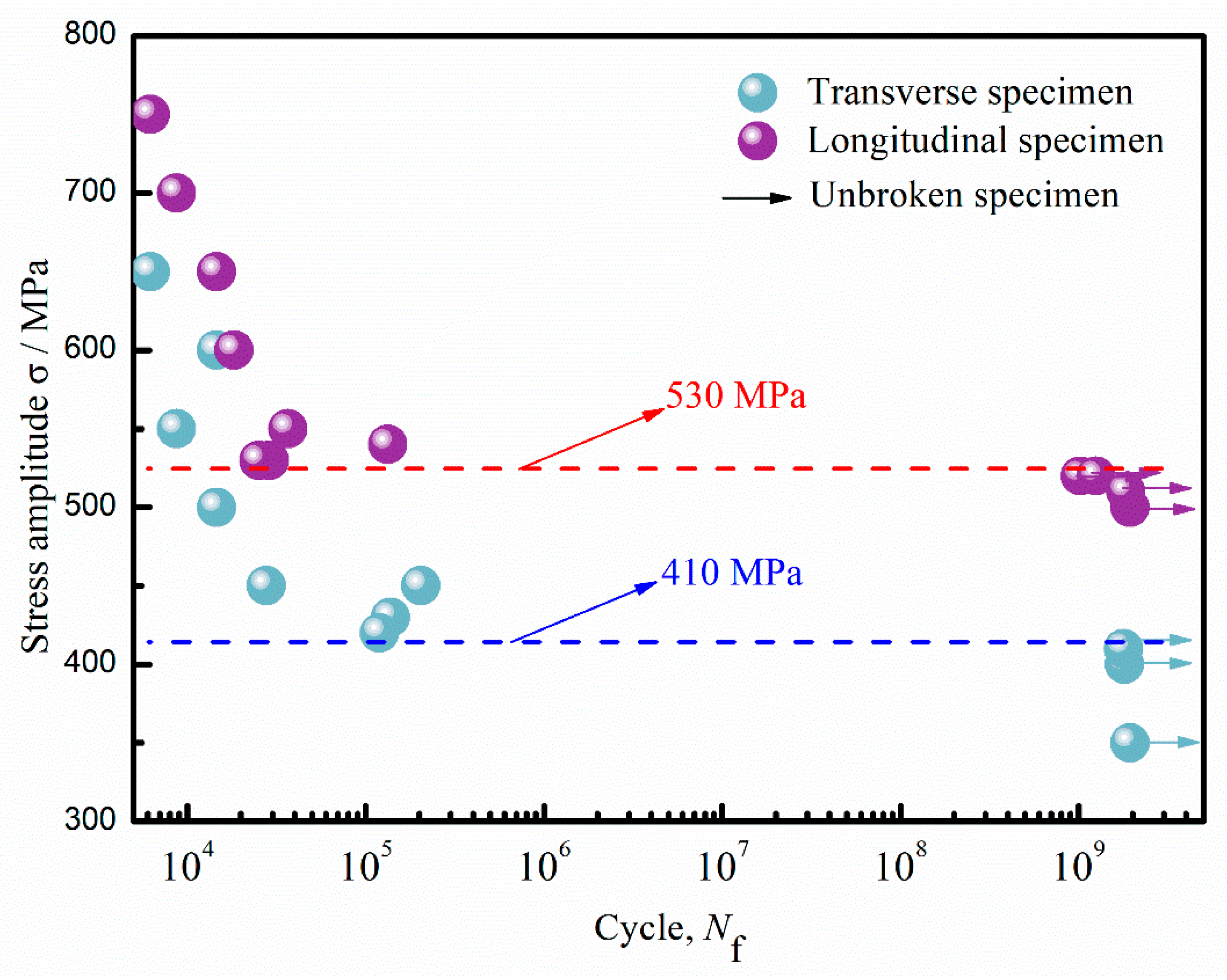
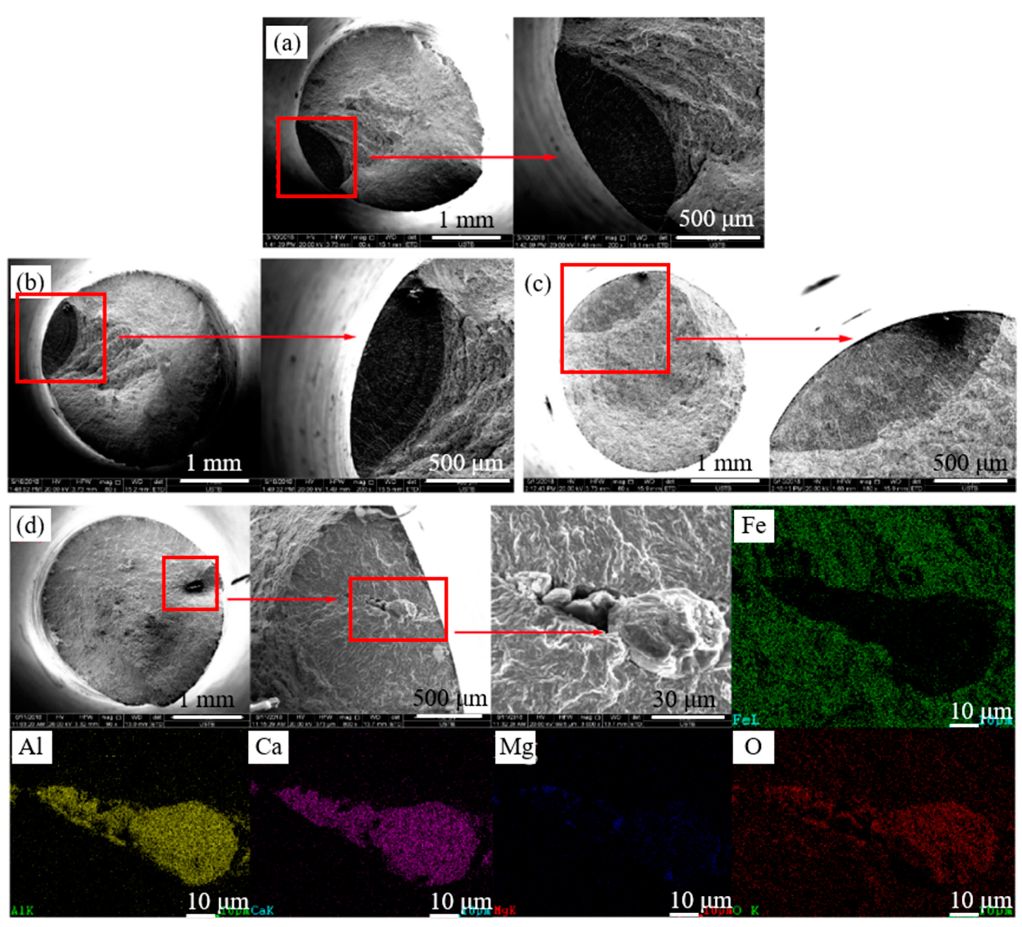
Different from the general fatigue test results, there is a critical value in the relationship between the fatigue life and the loading stress of 18CrNiMo7-6 gear steel. The specimen will fail after the stress exceeds the critical value. However, fatigue failure hardly occurs when the stress is below the critical value. Meanwhile, the gear steel 18CrNiMo7-6 contained inclusions such as Al2O3-CaO, which is prone to fatigue failure.

Author Contributions

Data curation, M.W., P.G. and C.G.; writing—original draft preparation, M.W. and W.X.; writing—review and editing, W.X., M.W. and Y.-P.B.; supervision, Y.-P.B. All authors have read and agreed to the published version of the manuscript.

Funding

This research was funded by the National Natural Science Foundation of China (No. 51774031).

Acknowledgments

The authors wish to express their gratitude to the foundation for providing financial support.

Conflicts of Interest

The authors declare no conflict of interest.

References

  1. Farfán, S.; Rubio-González, C.; Cervantes-Hernández, T.; Mesmacque, G. High cycle fatigue, low cycle fatigue and failure modes of a carburized steel. Int. J. Fatigue 2004, 26, 673–678. [Google Scholar] [CrossRef]
  2. Mohammad, A.; Alahmari, M.A.; Moiduddin, K.; Mohammed, K.M.; Alomar, A.; Renganayagalu, K.R. Porous γ-TiAl structures fabricated by electron beam melting process. Metals 2016, 6, 25. [Google Scholar] [CrossRef] [Green Version]
  3. Luo, C. Development and application of high strength automotive carburizing gear steels. Steelmaking 2006, 22, 56–59. [Google Scholar]
  4. Yuta, I.; Kunikazu, T.; Kimihiro, N. Development of carburizing steel for innovation in parts manufacturing process. JFE Tech. Rep. 2018, 23, 36–42. [Google Scholar]
  5. Manigandan, K.; Srivatsan, T.S. On the specific role of microstructure in governing cyclic fatigue, deformation, and fracture behavior of a high-strength alloy steel. JMEPEG 2015, 24, 2451–2463. [Google Scholar] [CrossRef]
  6. Garrison, W.M. The effect of Toughness of a 0.4 Carbon Low Alloy Steel. Metall. Trans. 1986, 17A, 669–678. [Google Scholar] [CrossRef]
  7. Tanaka, H.; Nishihara, R.; Miura, R.; Tsujino, R.; Kimura, T.; Nishi, T.; Imoto, T. Technology for cleaning of molten steel in tundish. ISIJ Int. 1994, 34, 868–875. [Google Scholar] [CrossRef]
  8. Donzella, G.; Faccoli, M.; Mazzù, A.; Petrogalli, C.; Desimone, H. Influence of inclusion content on rolling contact fatigue in a gear steel: Experimental analysis and predictive modelling. Eng. Fract. Mech. 2011, 78, 2761–2774. [Google Scholar] [CrossRef]
  9. Furuya, Y.; Abe, T.; Matsuoka, S. Inclusion-controlled fatigue properties of 1800 MPA-class spring steels. Metal. Mater. Trans. A 2004, 35, 3737–3744. [Google Scholar] [CrossRef]
  10. Cho, J.W.; Emi, T.; Shibata, H.; Suzuki, M. Heat Transfer across mold flux film in mold during initial solidification in continuous casting of steel. ISIJ Int. 1998, 38, 834–842. [Google Scholar] [CrossRef]
  11. An, J.; Wang, Z.; Li, R.; Li, T.; Ding, K.; Li, R. Cleanliness of automobile gear steel 8620RH. China Metal. 2016, 26, 33–37. [Google Scholar]
  12. Dong, Y.; Jiang, Z.; Gong, W. Source analysis of inclusions in gear steel of 20CrNiMoH. J. Mater. Metal. 2003, 2, 253–256. [Google Scholar]
  13. Payandeh, Y.; Soltanieh, M. Oxide inclusions at different steps of steel production. J. Iron Steel Res. Int. 2007, 14, 39–46. [Google Scholar] [CrossRef]
  14. Nordin, E.; Alfredsson, B. Experimental Investigation of Shot Peening on Case Hardened SS2506 Gear Steel. Exp. Tech. 2017, 41, 433–451. [Google Scholar] [CrossRef]
  15. Qiao, X.; Sun, P. Quantitative study of Ca content and sulfide morphology in the free cutting steel. J. Huazhong Uni. Ofence Technol. 1995. [Google Scholar] [CrossRef]
  16. Bao, Y.; Wang, M.; Jiang, W. A method for observing the three-dimensional morphologies of inclusions in steel. Int. J. Min. Metal. Mater. 2012, 19, 111–115. [Google Scholar] [CrossRef]
  17. Yang, S.; Li, J.; Zhu, L.; Chen, Y.; Zhang, L. Status quo of research on MgAl2O4 spinel inclusion in steel and trend of its development. Steelmaking 2010, 26, 74–78. [Google Scholar]
  18. Deng, Z.; Zhu, M.; Zhong, B.; Gao, X. Effect of deoxidation methods on inclusions in steel. J. Univ. Sci. Technol. Beijing 2012, 34, 1256–1261. [Google Scholar]
  19. Dong, W.; Ni, H.; Zhang, H.; Lv, Z.; Wu, Y. Control of magnesia-alumina spinel inclusions in the ultra-low-oxygen gear steel 28MnCr5. J. Iron Steel Res. 2015, 27, 14–18. [Google Scholar]
  20. Hu, Q.; Zhao, J.; Zhu, S. On Formation and prevention of non-metallic inclusion of heavy forgings. J. Netshape Form. Eng. 2011, 3, 69–71. [Google Scholar]
  21. Wakoh, M.; Sawai, T.; Mizoguchi, S. Effect of S content on the MnS precipitation in steel with oxide nuclei. ISIJ Int. 1996, 36, 1014–1021. [Google Scholar] [CrossRef] [Green Version]
  22. Guo, B.; Bao, Y.; Wang, M.; Lin, L. Effects of w(Ca)/w(Al) on transformation of inclusions in the calcium treatment in 20Mn2 steel. Steelmaking 2015, 31, 36–44. [Google Scholar]
  23. Gong, J.; Wang, Q. Thermodynamic analysis of calcium treatment on liquid steel. Steelmaking 2003, 19, 56–59. [Google Scholar]
  24. Li, X.; Yang, M.; Zhou, X.; Guo, J. Torsion fatigue characteristics and crack propagation behavior of 15Cr14Co12Mo5Ni2 gear steel. Iron Steel 2017, 52, 84–91. [Google Scholar]
  25. Wang, M.; Bao, Y.P.; Cui, H.; Wu, H.J.; Wu, W.S. The composition and morphology evolution of oxide inclusions in Ti-bearing ultra low-carbon steel melt refined in the RH process. ISIJ Int. 2010, 50, 1606–1611. [Google Scholar] [CrossRef] [Green Version]
  26. Gu, C.; Wang, M.; Bao, Y.; Wang, F.; Lian, J. Quantitative analysis of inclusion engineering on the fatigue property improvement of bearing steel. Metals 2019, 9, 476. [Google Scholar] [CrossRef] [Green Version]
  27. Xiao, W.; Wang, M.; Bao, Y. The research of low-oxygen control and oxygen behavior during RH process in silicon-deoxidization bearing steel. Metals 2019, 9, 812. [Google Scholar] [CrossRef] [Green Version]
  28. Spriestersbach, D.; Grad, P.; Kerscher, E. Influence of different non-metallic inclusion types on the crack initiation in high-strength steels in the VHCF regime. Int. J. Fatigue 2014, 64, 114–120. [Google Scholar] [CrossRef]
Figure 1. Sampling preparation of 18CrNiMo7-6 forge piece.
Metals 10 00201 g001
Figure 2. Three-dimensional morphologies, (a) Al2O3, (c) Al2O3-MgO, (e) Al2O3-SiO2, and (g) MnS; and compositions of inclusions, (b) Al2O3, (d) Al2O3-MgO, (f) Al2O3-SiO2, and (h) MnS.
Metals 10 00201 g002
Figure 3. Calculated inclusion stability diagrams of the Fe-Si-Mg-O system (a) and the Fe-Si-O system (b) at 1600 °C.
Metals 10 00201 g003
Figure 4. Size distribution of (a) Al2O3-CaO, (b) Al2O3, (c) Al2O3-MgO, (d) Al2O3- SiO2, and (e) all oxide inclusions at different locations.
Metals 10 00201 g004
Figure 5. Accumulative quantity density of different sizes of oxide inclusions.
Metals 10 00201 g005
Figure 6. Size distribution of (a) Al2O3-MnS, (b) Al2O3-MgO-MnS, (c) Al2O3-CaO-MnS, (d) MnS, and (e) all sulfide inclusions at different locations.
Metals 10 00201 g006
Figure 7. Accumulative density of different sizes of sulfide inclusions.
Metals 10 00201 g007
Figure 8. Relationship between oxide sizes and accumulative oxygen in oxides per unit volume.
Metals 10 00201 g008
Figure 9. Relationship among dissolved oxygen, bound oxygen in oxides, and bound oxygen in composite inclusions at different locations.
Metals 10 00201 g009
Figure 10. S-N curve of the internal crack initiation.
Metals 10 00201 g010
Figure 11. Fracture surfaces of the failed specimens, (ac); and Al2O3-CaO inclusions in the fatigue source (d).
Metals 10 00201 g011
Table 1. Chemical composition of gear steel 18CrNiMo7-6 (wt %).
CSiMnPSCrNiMoAlMg
0.15–0.20≤0.400.50–0.90≤0.020.01–0.021.50–1.801.40–1.700.25–0.350.030.0003

