Article

High Velocity Oxygen Liquid-Fuel (HVOLF) Spraying of WC-Based Coatings for Transport Industrial Applications

1
Faculty of Mechanical Engineering, Technical University of Košice, Mäsiarska 74, 040 01 Košice, Slovakia
2
Research Centre of the University of Žilina, University of Žilina, Univerzitná 8215/1, 010 26 Žilina, Slovakia
3
Department of Industrial Automation, Ternopil Ivan Puluj National Technical University, 46001 Ternopil, Ukraine
4
Department of Mobile Machinery and Railway Transport, Vilnius Gediminas Technical University, Plytinės g. 27, LT-10105 Vilnius, Lithuania
*
Author to whom correspondence should be addressed.
Metals 2020, 10(12), 1675; https://doi.org/10.3390/met10121675
Submission received: 2 November 2020 / Revised: 9 December 2020 / Accepted: 11 December 2020 / Published: 14 December 2020
(This article belongs to the Special Issue Application of Alloys in Transport)

Abstract

:
In this article, we analyse five types of coatings, in terms of their microstructure, hardness, porosity, and wear resistance, in the as-sprayed state. The coatings are WC-based (WC-FeCrAl, WC-WB-Co, and WC-NiMoCrFeCo), alloy-based (Co-MoCrSi), or nanoWC coating-based (nanoWC-CoCr). Two tests were applied to assess the wear resistance of the coatings: a dry-pot wear test with two impact angles and an abrasive test using an abrasive cloth with two grit sizes. Porosity was determined by image analysis. Vickers impression was performed on cross-sections of the coatings, in order to determine their indentation fracture toughness. The highest hardness of the tested coatings was recorded for the nanoWC coating, followed by the rest of the WC-based coatings; meanwhile, the lowest hardness was recorded for the alloy coating. Minimal porosity was achieved by the alloy coating, due to its different nature and the absence of hard particles with a higher melting point. The NanoWC coating and other WC-based coatings had a higher porosity; however, porosity did not exceed 1% for each coating. The best wear resistance was achieved by the nanoWC coating, followed by the other WC-based coatings, with the lowest obtained by the alloy coating. The same tendency was recorded when determining the indentation fracture toughness. From a microscopic point of view, the structure of the evaluated coatings is not compact; nevertheless, their properties are excellent, and they act as compact coatings under load.

1. Introduction

The transport industry (i.e., aerospace, marine, and automotive) is in need of new materials and developments. In addition to higher fuel efficiency and a broader range of new applications, these are expected to contribute to higher safety, environmental compatibility, lower costs, lower weight, reduced maintenance, and extended durability [1]. Thermal spraying of coatings is an important surface engineering technique used in all industrial areas (including transport), for primary production as well as the renovation of parts. A wide range of metals or ceramics can be sprayed onto the surface of various materials, including steel, aluminium alloys, and magnesium or titanium alloy substrates. In this way, the choice of a proper coating—primarily for wear and corrosion protection, the repair of worn components, or hard chrome replacement—is of great importance and can lead to a technically superior and commercially competitive solution [2,3]. Current coating materials and techniques are able to fulfil the required goals for various kinds of hydro, industrial heavy vessel, automobile, and aircraft components [4]. However, improvements are still expected, such as in the coating deposition in narrow areas or complex parts/geometries, either internally or externally, and with the application of sensors, used in the harsh environment of spray booths, to improve the reproducibility and reliability of coatings sprayed with hot or cold gases. One way to obtain higher or new value coatings is the possibility of applying tailored coatings which allow for the adjustment of surface properties, such as: (I) mechanical (wear, friction), (II) chemical (corrosion, permeation, temperature insulation, biocompatibility, wettability), (III) electrical (conductivity), and (IV) optical (transmission, reflection, absorption, colour) properties [5]. Properly selected and applied coatings significantly increase the life and reliability of the coated materials [6]. Advanced surface treatments of materials, such as the coatings used currently, may be able to carry out multiple functions in devices where two bodies are in relative movement (e.g., to support the load, lower friction, provide self-healing capability, or facilitate energy absorption), enabling the design of products, machinery, vehicles, and services for use in our daily lives [7]. The expansion of thermal spray techniques—including the High Velocity Oxy-Fuel (HVOF) technique—has taken place recently, thanks to the development of materials, equipment, and diagnostic tools, as well as understanding of the processes with the aim to green tribology applications [8]. Among the ways that materials research can contribute to the green deal is the possibility to tailor the tribological behaviour of the surface treatments for products and processes [7].
Trends in the HVOF thermal spraying technique [1] field can be characterized by the following:
  • Development of Nanoparticles and Nanocoatings
As stated in [9,10,11], thermally sprayed nanocoatings mainly include three types:
  • Nanocrystalline coatings, composed of only one material;
  • Nanocrystalline composite coatings, consisting of two or more nanomaterials;
  • Composite coatings reinforced with nanoparticles.
The addition of nanoparticles to traditional coatings can significantly improve the properties and functions of the coating at low cost [12,13,14,15,16].
  • Development of Thermal Spraying Processes Using Suspensions and Solution Precursors
Thermal spray coatings from liquid feedstocks, such as suspensions and solution precursors, have attracted increased attention from the scientific community, due to the unique properties of the coating that can be achieved by the use of such processes. Some research teams have carried out their work based on plasma, as well as using HVOF processes in the production of advanced nano-structured and nano-phased materials [17,18].
  • Ecologization
In terms of the ecologization of thermal spraying, innovations are generally represented by so-called “green carbides”. Recently, cermet coatings containing hard WC particles in a metal matrix applied by HVOF technology have been considered as a less dangerous and more environmentally friendly alternative to hard chromium plating [19,20,21,22,23]. As WC-based powders contain heavy metals, such as Co and Ni, there are very strict logistics of the powders used to form the coatings in the HVOF process. At present, the efforts of materials scientists are focused on the development of new powders, in which elements such as Co and Ni in the metal matrix are eliminated and replaced by other alloys. One such replacement is powder WC-FeCrAl, called “green carbides” [24,25].
  • Development of a New Generation of HVOF Systems
A new generation of HVOF systems, the so-called high-pressure HVOF systems (HP-HVOF), enable the efficient production of very dense carbide layers. The pressure in the combustion chamber (as one of the options to increase the efficiency of the system) needs to be regulated, in order to meet existing safety standards for oxygen supply. Kerosene/oxygen combustion is still the most environmentally friendly and the simplest solution for designing a new generation of high-performance HP-HVOF systems. As particle acceleration is determined mainly by particle size and momentum, the system design must be carried out hand-in-hand with the powder design [26]. As published in [27], newly developed HVOF spray guns operating at elevated pressure in the combustion chamber have shown high potential for spraying metal coatings that do not present the high ductility of pure copper or aluminium.
  • Post-treatment of the HVOF Coating
Thermally applied coatings have high surface roughness, often above the required limit for many industrial applications. Such coatings need to be completed, in order to achieve the required surface quality and shape accuracy. Post-processing techniques are also needed, in order to remove the applied defects and to improve the properties of the coating [28,29]. The laser remelting technique is considered a promising and effective method to improve the surface of coatings, remove microstructural defects such as pores and cracks, and increase component and equipment life by enhancing microhardness and increasing adhesion between the coating and substrate [30,31,32]. Laser remelted coatings have a much denser and more homogeneous structure with excellent metallurgical bonding between particles. Significant reduction in surface roughness has also been observed on the surface of laser post-treated coatings [30].
  • Process Maps for Thermal Spraying (TS Maps)
The relationships between process, structure, and properties can be presented using process maps, which can be used as a design tool for coating processing. Process maps represent the relationships between process variables and output effects [33]. The process map methodology has been developed for process control and optimization of coating properties. In the process mapping concept, diagnostic tools are used to understand the basic relationships in the thermal spraying process, from the powder through to the thermal spraying process, the formation of the coating, the characteristics of the coating and, finally, to the effectiveness of the coating. TS maps are based on critical coating characteristics (i.e., the microhardness, adhesive strength, and modulus of elasticity) of hot spray coatings [34]. The process optimization mapping tool has been widely used for the plasma spray process [33,35], but can also be successfully used for the HVOF process [36,37,38].

Application of HVOF and nanoHVOF Coatings in Transport Industry

New thermal spray techniques, coatings, and materials are expected to have impacts in many industries, such as aerospace, automotive, marine, renewable/alternative energy, semiconductors, biomedicine, and metal production, ensuring the required properties of coated components with less wear and friction, corrosion, and oxidation, while enhancing their hardness and operating temperatures [1,39,40]. For example, cermet coatings sprayed with HVOF, such as 75Cr3C225 (Ni20Cr), can be applied to protect low weight aluminium components against wear without reducing their fatigue strength. Such coatings can be designed to meet modern environmental requirements for non-ferrous engine blocks, hybrid solutions for self-propelled aluminium engines, and coatings for engine cylinder bores for both petrol and diesel engines. Reinforced metal matrix composite (MMC) hard coatings, which are produced by thermal spray processes, can be used for various automotive parts, such as piston rings and cylinder liners. Generally, WC-CoCr coatings are deposited using the HVOF process, improving the surface resistance of low alloyed steels [41]. There is also a need for the development and implementation of tests and characterization methods specially adapted to ensure the higher reliability of heavy equipment and industrial tool coatings [42]. Typical thermal spray coatings used in different transport industries [1] are summarized in Table 1, while typical HVOF surface applications in transport industries [43] are summarized in Table 2.
Powders based on iron, nickel, cobalt, chromium carbide, tungsten carbide, and mixtures of these materials are generally used in nanoHVOF technology. NanoHVOF technology can solve problems relating to the replacement of hard chrome plating, corrosion, thermal barrier, fatigue, erosive, abrasive, vibrating, adhesive and cavitation wear, and electrical conductivity or non-conductivity. Compared to welding and chrome plating, nanoHVOF technology is a cheaper and faster renovation technology. New, advanced thermal spray technologies make it possible to deposit wear-resistant coatings on the cylindrical surfaces of aluminium or magnesium engines [40].
In this paper, we focus on the quality evaluation of five types of coatings applied by HVOF technology. Coatings suitable for application in the transportation field were selected. The WC-FeCrAl coating, with an environmentally friendly matrix without harmful elements of Co and Ni, as well as the WC-CoCr coating based on nanoparticles and coatings with WC particles were evaluated. The quality of the cermet coatings was compared with a commercially used Co-MoCrSi alloy coating. The quality of the coatings was evaluated in terms of porosity, hardness, indentation fracture toughness, and wear resistance.

2. Materials and Methods

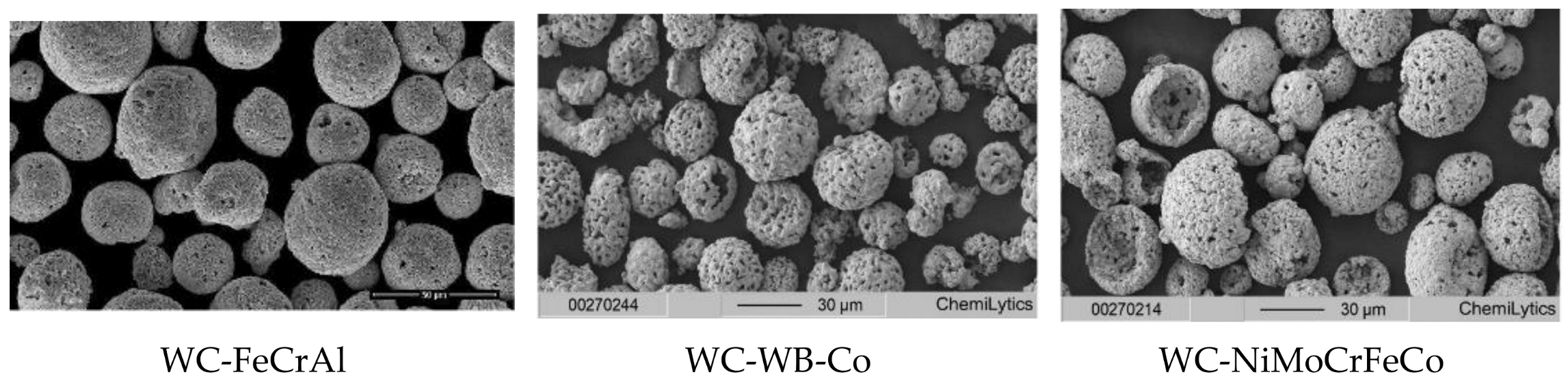
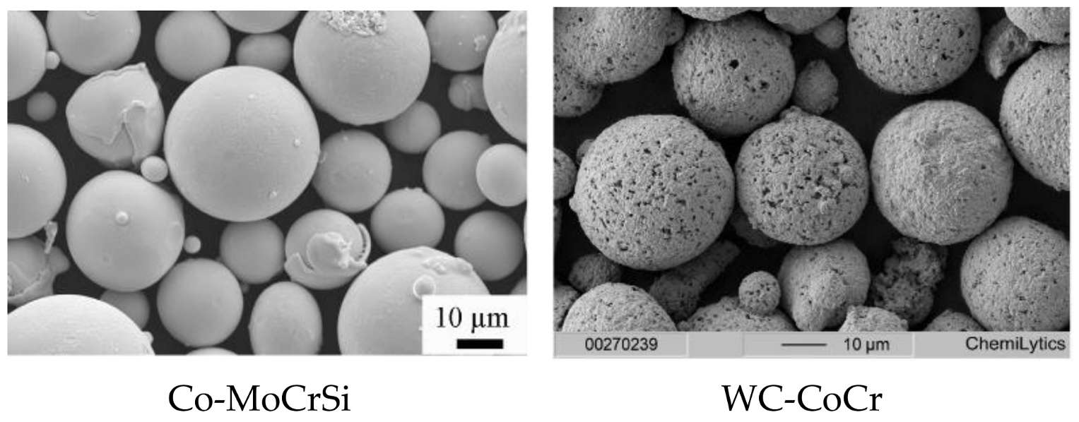
2.1. Base Materials and Powders for Coating Formation

Coatings were formed by HVOF spraying on a substrate made of 1.4404 steel: austenitic, low-carbon stainless steel, resistant to non-oxidizing environments, and designated for parts subject to high chemical stress. Table 3 shows the chemical composition of the substrate, as given by the steel producer (Acerinox, Germany).
The substrate has a cylindrical shape (ø 25 mm, length of 50 mm) with the coating sprayed on the head of the cylinder. The substrate material was prepared by degreasing and abrasive cleaning (abrasive: white corundum with particle size 0.56 mm, air pressure: 0.4 MPa, blasting distance: 300 mm, impact angle: 90°). Table 4 shows the chemical composition of the feedstock powders used, as given by the powder producer, while Figure 1 shows SEM imagery of the individual powders.
WC-FeCrAl (Höganäs, Sweden) has particle size −45/+15 µm and carbide/matrix ratio 85/15. This powder was developed especially for spraying with HVOF technology. The density and wear resistance of coatings made from this powder are comparable to that of a WC-Co coating. In NaCl solution, it exhibits better corrosion resistance than the WC-Co-Cr coating. It is environmentally friendly, without the presence of cobalt or nickel. It belongs to a group of new “green” carbides. It is characterized by excellent corrosion and erosion resistance in seawater and in neutral environments and environments with high pH. It is also characterized by good resistance to abrasive and cavitation wear.
WC-WB-Co (Höganäs, Sweden) has particle size −45/+15 µm and WC/WB/Co ratio 60/30/10. This powder can be applied using HVOF technology. It creates very dense and malleable coatings with good resistance to erosion, abrasion, cavitation, and corrosion. It is intended for the surface protection of parts used in marine environments, as well as rollers leading steel strips to a zinc bath.
WC-NiMoCrFeCo (Höganäs, Sweden) has particle size −45/+15 µm and carbide/matrix ratio 82/18. This is an innovative powder based on tungsten carbide with a highly corrosion-resistant matrix. It has been specially developed for HVOF application, forming coatings with high corrosion resistance, compared to standard coatings such as WC-Co-Cr or WC-Ni. It has improved performance when exposed to highly corrosive environments, such as seawater or diluted mineral and organic acids, while maintaining good wear resistance.
Co-MoCrSi (Praxair Surf. Technologies, Manchester, CT, USA) has particle size −45/+10 µm. This is an alloy, carbide-free powder, which is suitable for application by HVOF technology. It is characterized by good sliding properties and is resistant to corrosion and oxidation.
nanoWC-CoCr (Thermico, Dortmund, Germany) has particle size −15/+5 µm and carbide/matrix ratio 86/14. This coating is applied to hydraulic cylinders with high resistance to corrosion and wear, as well as to compressor shafts, valves, and rollers in the paper industry. The hardness of such coatings exceeds 1200 HV0.3.
The coatings were applied by HVOF technology, using the PRAXAIR TAFA JP 5000 (Praxair Surface Technologies Inc., Indianapolis, IN, USA) coating application system with HP/HVOF and Powder Feeder 1264 (Praxair Surface Technologies Inc., Indianapolis, IN, USA). The spraying parameters are shown in Table 5.

2.2. Microstructure of Coatings

Coatings deposited on face of steel cylinders were cut, ground, and polished to prepare metallographic cross-sections. Cross-sections were used for determination of the thickness of the coatings (ISO 1463: 2004-10, Olympus BXFM, Hamburg, Germany), indentation fracture toughness, microhardness of coatings (ISO 4516, Shimadzu HMV-2, Tokyo, Japan; load of 980.7 mN, dwell 15 s, 20 indentations per sample), and structure of coatings (Tescan Vega 3, TESCAN ORSAY HOLDING, a.s., Brno, Czech Republic). The internal structure of the coatings, remelting, and distribution of hard particles in the matrix were evaluated from the fracture surfaces.
The porosity of the coatings was also evaluated using the metallographic cross-sections, as a percentage of the pore area to the total evaluated coating area through image analysis using the Quick PHOTO Camera 2.3 software (Promicra, s.r.o., Prague, Czech Republic). The porosity was evaluated from micrographs taken at the same magnification, as an average from ten different cross-sectional areas of each coating.

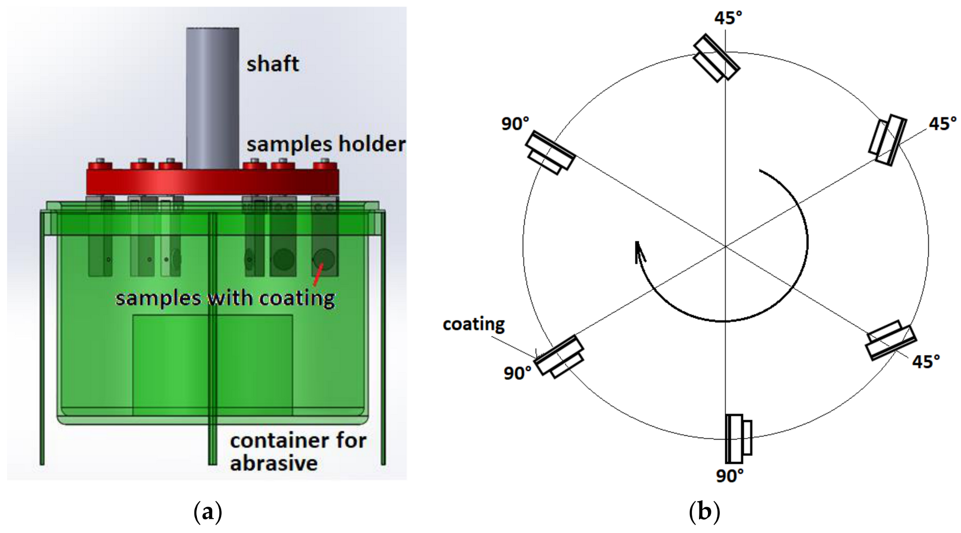
2.3. Dry-Pot Erosive Wear Test

The test coatings were in relative motion with respect to the dry abrasive placed in the vessel, being specifically oriented with respect to the axis of rotation such that the angle of contact of the coating with the abrasive was 45° and 90°, respectively; see Figure 2. The wear resistance was determined based on weight loss. Brown corundum with particle size 0.75 mm was used as the abrasive. The total duration of the test was 480 min. The test was repeated three times on each coating and at each contact angle.

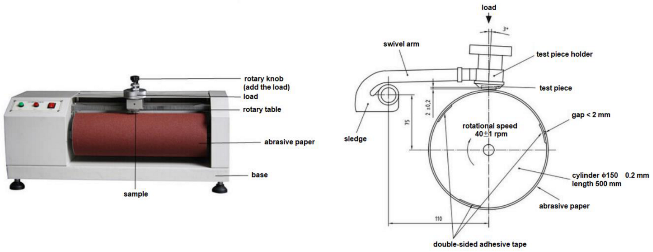
2.4. Abrasive Wear Test with Abrasive Cloth

An abrasive wear test of the coatings was performed on a laboratory test device APGi (VEB Leipzig, Germany), using an abrasive cloth; see Figure 3. The grit sizes of the corundum cloths were # 80 and # 120, respectively. The test parameters were: load, 10 N; peripheral speed, 0.33 m·s−1; and length of contact track between the sample and the cloth, 40 m. The wear resistance of the coatings was evaluated based on weight loss, and the test was repeated three times on each coating, using a new abrasive cloth for each test.

2.5. Indentation Fracture Toughness of Coatings

The Indentation Fracture Toughness (IFT) test was based on the indentation of a brittle material, usually by a Vickers pyramid which, when loaded more than critical, causes cracks to emerge at the corners of the impression. The value of the indentation fracture toughness can then be determined, depending on the magnitude of the applied load and the length of the induced cracks [44,45,46,47,48]. With a sufficiently high load, radial cracks form in the diagonals of the impression. These cracks can be of two types (Figure 4): radial central (central: having the shape of a semi-ellipse) or Palmqvist. Ten indentations were made on the cross section of each coating.
Several authors have dealt with the evaluation of fracture toughness. In 1957, the first study was carried out by Palmqvist, who determined failure resistance as the work required to create cracks. Exner, Lawn, Fuller, Charles, Clauer, Miranza, Moya, and others have also dealt with the determination of the IFT model [49,50,51,52], establishing a number of empiric formulas for the determination of IFT with respect to the assumed crack geometry.
The IFT of the evaluated coatings was determined on metallographic cross-sections of coatings. For indentation, a Bruker CETR UMT-2 test device (Billerica, MA, USA) equipped with a Vickers indentor with a load force of 40 N was used. The indentation size and crack length were measured using a Keyence VHX 5000 digital microscope (Osaka, Japan). As we did not measure the true E value of the coating and the use of a representative value of E would contribute to the overall error in the IFT calculation, we decided to use the LF model, which does not include the E/H (modulus to hardness) ratio.
Therefore, the indentation fracture toughness, KIc, was determined using the LF (Lawn and Fuller) model, according to the formula:
K I c = 0.0515 L a c 3 2 ,
where L is the test load, c is the sum of the crack length and half the diagonal indentation, a is half the indentation.

3. Results and Discussion

3.1. Microstructure of Coatings

The microstructures of the evaluated coatings, as determined by their metallographic cross-sections, are shown in Figure 5.
Based on the abovementioned methodology, the internal structures of the coatings and their chemical properties were evaluated. From Figure 5, it follows that the structures of the coatings, observed in terms of cross-sections, were dense, with no visible presence of pores or defects. The coatings were well-bonded to the substrate, mechanically anchored in the micro-irregularities created by the previous operation (abrasive blasting). At higher magnifications, the hard particles of WC or WB are visible, homogeneously dispersed in the matrix. The Co-MoCrSi alloy-based coating had a different structure from the others, with a distinct pattern of individual splats as a sign of sufficient melting during spraying. Due to manual operation of the spraying nozzle, the thickness of coatings varied between 200 and 420 µm
Figure 6 shows the fracture surfaces of the WC-FeCrAl coating at magnifications of 2000×, 5000×, and 10,000×. Figure 7 shows the chemical analysis of the WC-FeCrAl coating.
On the fracture surface of the WC-FeCrAl coating in as-sprayed state, it is possible to see non-melted tungsten carbide particles, the imperfections of the coating, and the presence of small pores. The sandwich structure typical of this type of coating—due to particle deformation during impact and splat formation—is also evident.
Spectrum 12 shows the detail of the darker component of the coating. In this spectrum, chromium had the highest content (36.2%), while the lowest content was aluminium (0.5%). Spectrum 13 shows a detail of the light area of the coating. In this spectrum, tungsten had the highest content, up to 84.5%. The lowest content was again aluminium (0.4%). Based on the structural analysis, it can be stated that the lighter areas of the coating consisted of tungsten carbide, while the darker areas also contained tungsten carbide, as well as the FeCrAl alloy, which formed the coating matrix.
Figure 8 shows the fracture surfaces of the WC-WB-Co coating at magnifications of 2000×, 5000×, and 10,000×. Figure 9 shows the chemical analysis of the coating.
For the WC-WB-Co coating in the as-sprayed state, a spongy structure and a lack of compactness of the coating can be observed. Harder tungsten particles can be seen in the softer metal matrix, which were mostly non-melted.
Spectrum 14 shows the detail of the light area of the WC-WB-Co coating. Tungsten had the highest content (92.5%). The lowest content was aluminium (0.6%). Spectrum 15 shows a detail of the darker area of the coating. In this spectrum, chromium had the lowest content (0.3%), while tungsten showed the highest content (88.5%). Based on the analysis, it can be stated that both the lighter and darker areas had a high content of tungsten.
Figure 10 shows the fracture surfaces of the WC-NiMoCrFeCo coating at different magnifications. Figure 11 shows chemical analysis of the WC-NiMoCrFeCo coating.
A spongy structure can be observed on fracture surface of the WC-NiMoCrFeCo coating. Non-melted tungsten particles are present.
In spectrum 21, tungsten exhibited the highest content (85.3%), while the lowest content was aluminium (0.7%). This spectrum shows a detail of the light part of the coating. Spectrum 24 shows the detail of the darker region of the coating. In this spectrum, cobalt showed the lowest content (0.6%), while tungsten had the highest content (62.5%). Based on the analysis, we can state that the lighter areas of the coating contained tungsten and the darker areas corresponded to the coating matrix, composed of the NiMoCrFeCo alloy.
Figure 12 shows the fracture surfaces of the Co-MoCrSi alloy coating at various magnifications. Figure 13 shows the chemical analysis of the Co-MoCrSi coating.
The most pronounced inhomogeneity was observed on the Co-MoCrSi alloy coating, where a pronounced drawing of the molten particles that made up the coating itself was visible. It is possible to observe a significant sandwich structure and the formation of splats with the presence of pores.
Spectrum 43 shows the detail of the light part of the Co-MoCrSi coating. Cobalt had the largest share in this spectrum (60.4%), while the lowest content was exhibited by oxygen (1.4%). In spectrum 39, cobalt also had the largest share (45.8%), while aluminium had the lowest content (0.1%). This spectrum shows the detail of the darker region of the Co-MoCrSi coating. Based on the analysis, we can state that, in the darker and lighter areas, cobalt—which is the main component of this coating—had the largest share.
Figure 14 shows the fracture surfaces of the WC-CoCr coating at different magnifications. Figure 15 shows chemical analysis of the WC-CoCr coating.
The finest structure was observed on the WC-CoCr coating; nevertheless, pores and non-melted tungsten particles were still visible on this coating.
In spectrum 31, tungsten had the highest content (74.0%), while the lowest content was that of iron (1.0%). This spectrum shows the detail of the light part of the WC-CoCr coating. Spectrum 34 shows the detail of the darker area of the coating. Again, tungsten had the highest content in this spectrum (82.4%), while aluminium had the lowest content (0.4%).
The porosity of the coatings was evaluated in the metallographic cross-sections, as a percentage of the pore area to the total evaluated coating area; see Figure 16 and Figure 17. The porosity and hardness of HVOF-sprayed coatings depend on the oxygen flow rate (O), kerosene flow rate (L), powder feed rate (F), and spray distance (S); so, can be expressed as: Responses = f (O;L;F;S).
The highest occurrence of porosity was measured in the WC-FeCrAl coating, which had the lowest hardness value of the evaluated coatings containing WC particles; see Figure 17. The lowest porosity of all evaluated coatings was shown by the Co-MoCrSi coating. This is a different type of coating: an alloy coating without the presence of hard carbide particles. This coating also exhibited the lowest hardness value. The WC-CoCr nanocoat showed the highest hardness value of the evaluated coatings, while its porosity was the lowest of the group of coatings containing WC particles.
These measurements clearly show that the porosity of metallic–ceramic coatings, in addition to the technological parameters of coating spraying, depends on their hardness. However, this does not apply to alloy coatings, for which the mechanism of coating formation is different. It has been stated that the porosity values of the coatings applied by HVOF technology do not exceed 1%, which was confirmed for the evaluated coatings. The different porosity of the evaluated coatings was due to the different matrices, the type and distribution of hard carbide particles in the matrix, and the volume fraction of particles in the matrix. Our experiment demonstrated the high quality of coatings applied by HVOF technology.

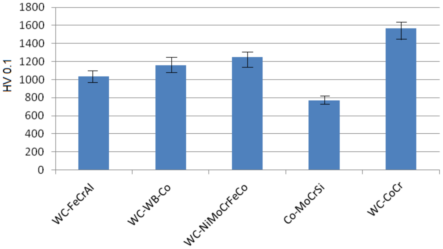
3.2. Hardness of the Coating

The microhardness values of the base material ranged from 278 to 304 HV 0.1. Between the evaluated coatings, the highest hardness value was obtained with the WC-CoCr nanoparticle coating. The lowest hardness was exhibited by the Co-MoCrSi alloy coating, as shown in Figure 18.

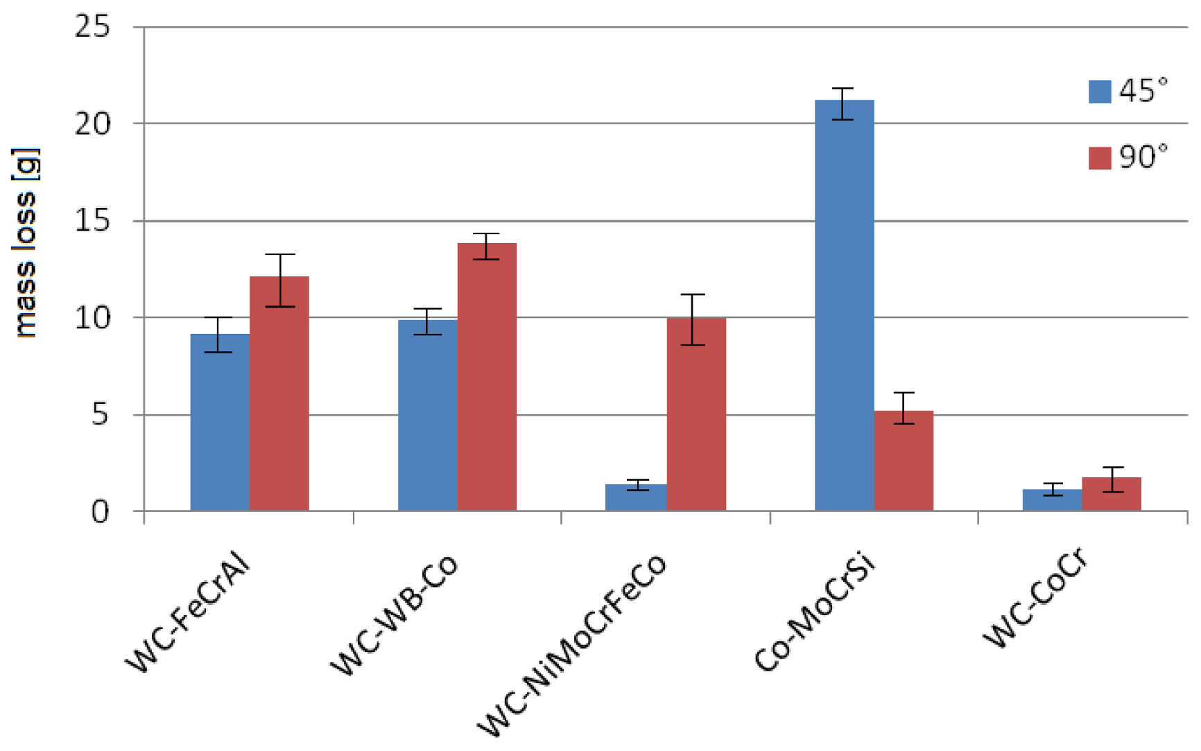
3.3. Dry-Pot Erosive Wear Test

The resistance of the coatings under erosive wear conditions was evaluated by the dry-pot erosive wear test at the two impact angles of 45° and 90°; see Figure 19. Based on the measured values of mass loss of WC-containing coatings, a larger weight loss was recorded in samples with an impact angle of 90°, in agreement with the literature, concerning the wear of hard materials [53,54]; however, the Co-MoCrSi coating showed greater wear at an impact angle of 45°, compared to that at 90°. This is another type of coating, without hard WC particles, and its hardness reached the lowest value (767 HV 0.1). At lower abrasive impact angles, the grooving effect of the particles predominates in relatively softer materials; thus, the mechanism of wear is microcutting. The lowest value of wear within all evaluated coatings was achieved by the coating with WC-CoCr nanoparticles at both impact angles.

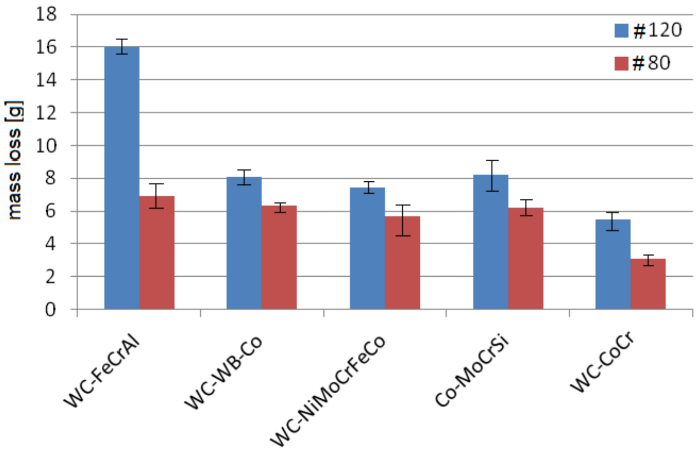
3.4. Abrasive Test with Abrasive Cloth

In the abrasive wear test using abrasive cloth, the coatings were subjected to dry friction with two abrasive cloths of different grit sizes, # 120 and # 80; see Figure 20. In the test, hard SiC particles acted against another body, that is, the coating. In practice, the damage is investigated in relation to the real functional surfaces of machine parts. As can be seen from previous research, the worn volume is directly proportional to the load and the length of the track, and indirectly proportional to the hardness of the worn surface. During the test, abrasive particles fixed on the cloth come into contact with the surface of the coating and (firstly elastic, later plastic) contact occurs at the contact point. Gradually, the number of contact points that transmit external forces increases. Obviously, the abrasive cloth cannot be considered as a perfectly rigid body and, so, it is relatively difficult to analyse the exact conditions in the contact area. Higher wear in all evaluated coatings was achieved with abrasive cloth with a larger number of grains per unit area and smaller grain size, that is, with the # 120 grit size. Although the abrasives were smaller in size, the wear was caused by a larger number of abrasive grains. Of the evaluated coatings, the lowest wear was obtained by the WC-CoCr nanocoating. The reason for this lies in the general fact that the mechanical properties and wear resistance of WC-based coatings generally increase with the decrease in WC particle size [55].

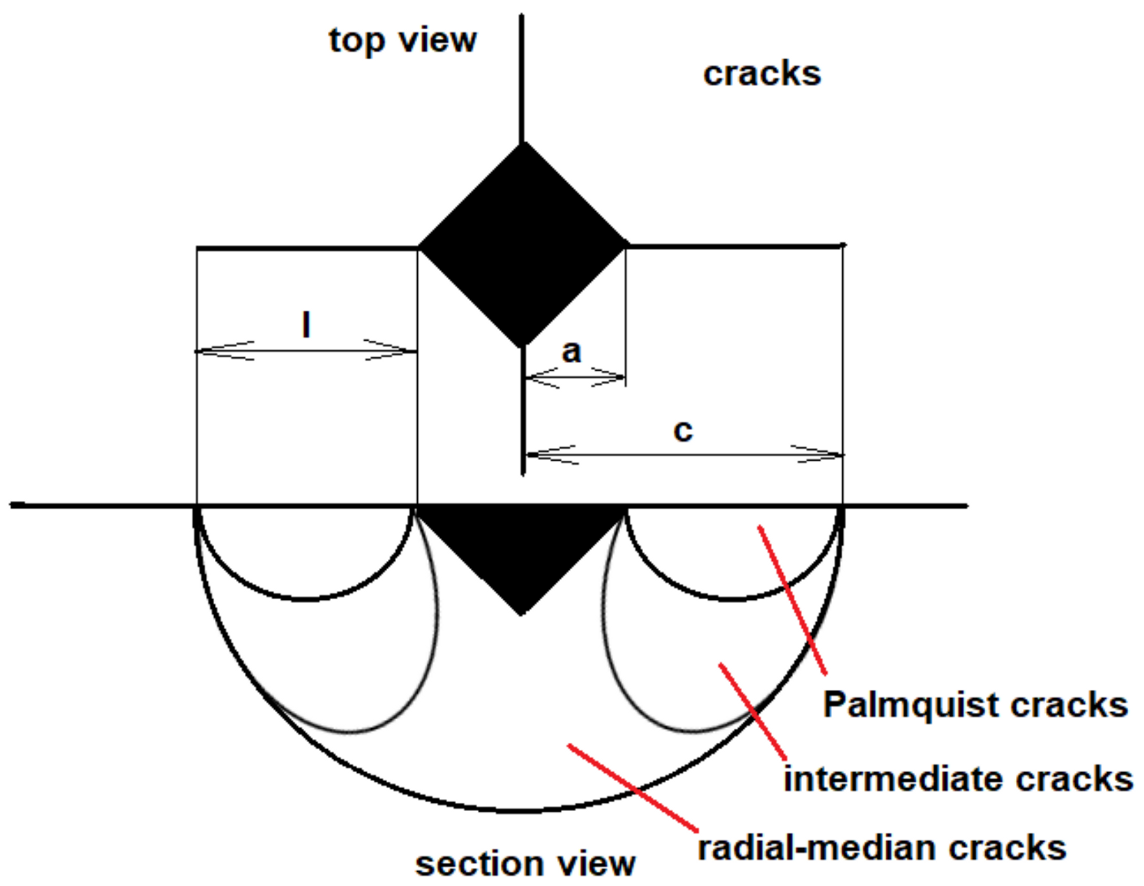
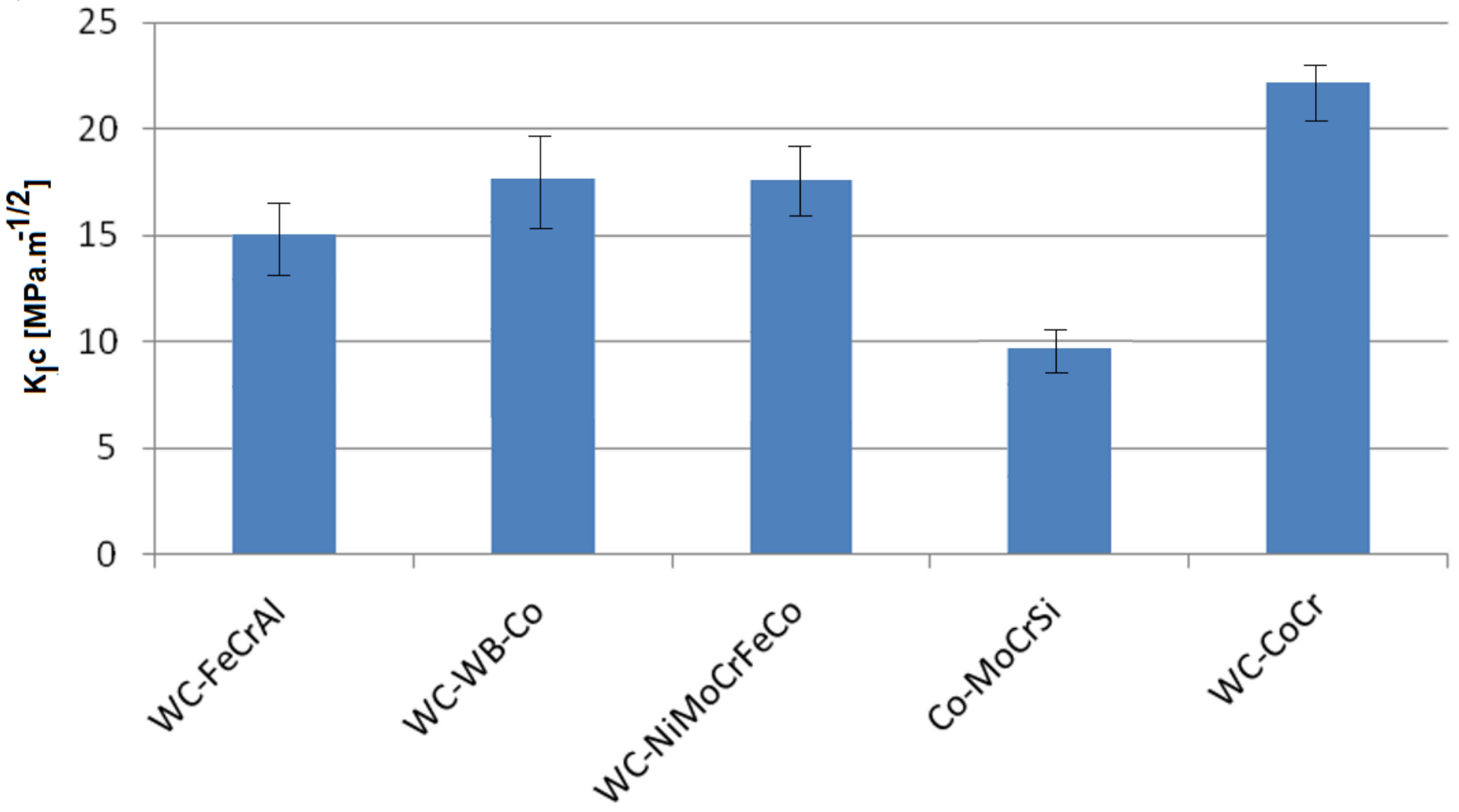
3.5. Indentation Fracture Toughness of Coatings

The evaluation of the fracture toughness of thermally sprayed coatings is especially important in the case of wear-resistant materials. Together with the hardness, modulus of elasticity, and Poisson’s constant, it characterizes the ability of the material to withstand the stresses caused by wear. Due to their structure, the fracture toughness of thermally sprayed coatings differs from that of bulk materials of the same composition. Its value depends on the degree of porosity, the presence of oxides, and the shape, size, and distribution of the reinforcing particles. The lamellar structure of the coating causes significant anisotropy in the resistance to crack propagation in the coating [55,56].
Based on the calculated values of the indentation fracture toughness of the coatings, it was found that the highest resistance to crack propagation was achieved by the WC-CoCr nanocoating; see Figure 21. Lower values were achieved by the cermet coatings containing WC particles, while a significantly lower value was achieved by the Co-MoCrSi alloy coating. In the case of cermet coatings, the resistance to crack propagation is determined primarily by the proportion and material of the matrix. The homogeneity of the structure and porosity also play significant roles. In this respect, the more porous coatings, such as WC-FeCrAl and WC-WB-Co, are more prone to crack propagation. Thus, cermet coatings cannot be considered a suitable material for applications requiring resistance to crack propagation, such as erosion at high angles.

4. Conclusions

This research focused on the characterization of cermet coatings based on WC applied by HVOF technology. The properties of the coatings were compared with a commercially used Co-MoCrSi alloy coating. The quality of the environmentally friendly WC-FeCrAl coating without cobalt and nickel was determined. The WC-CoCr coating was based on nanopowders. The aim of this work was to determine the possibility of replacing coatings containing carcinogenic elements, such as cobalt and nickel, with new types of green carbides, as well as to determine the quality of the coating using nanopowders.
The experimental work led to the following conclusions:
-
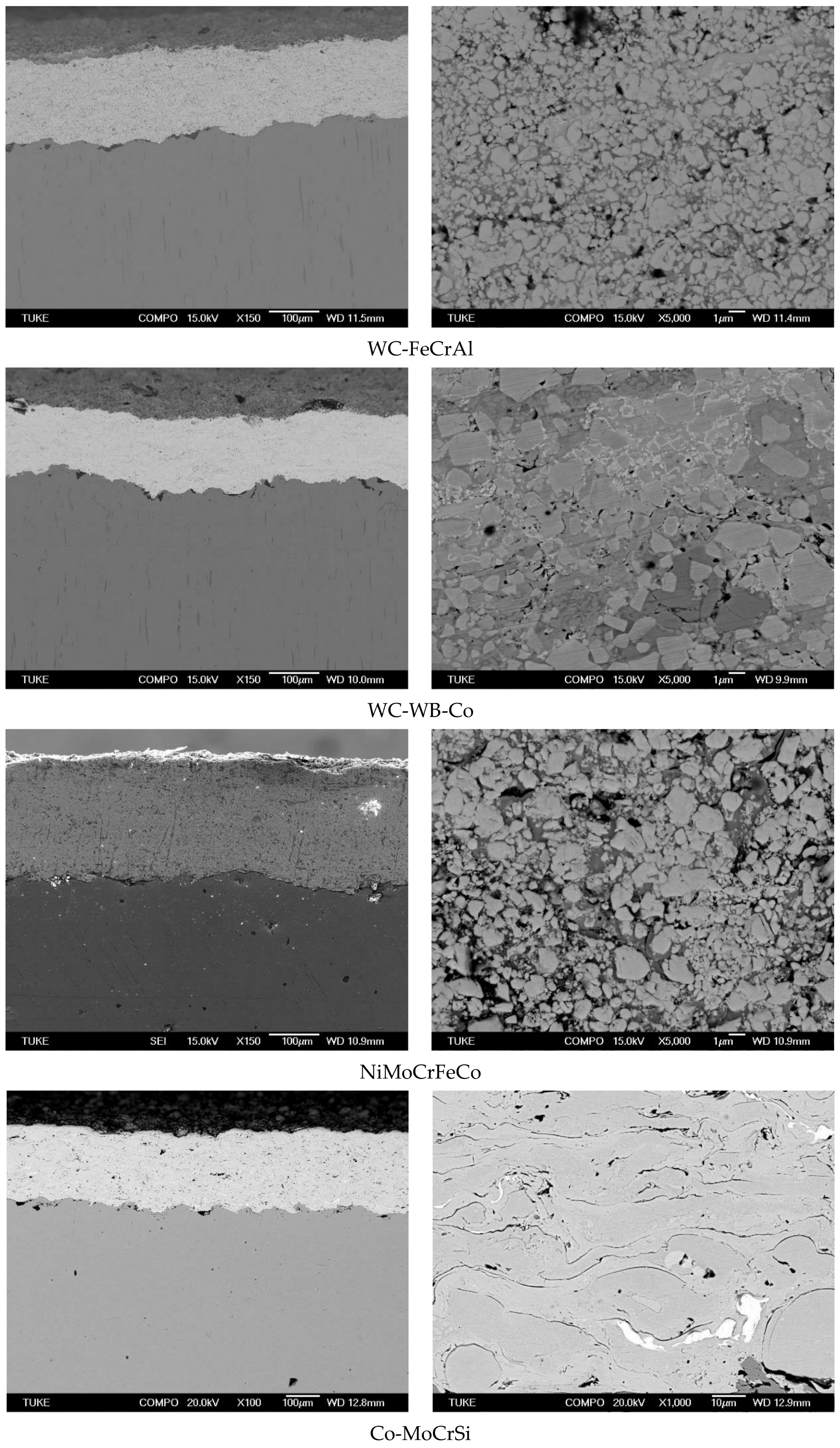
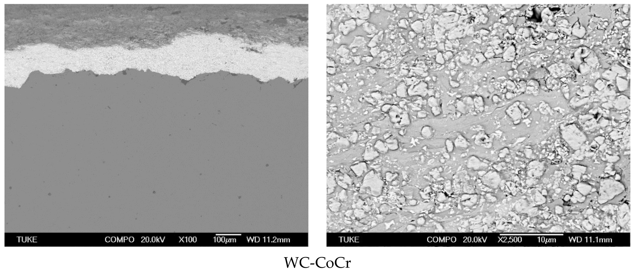
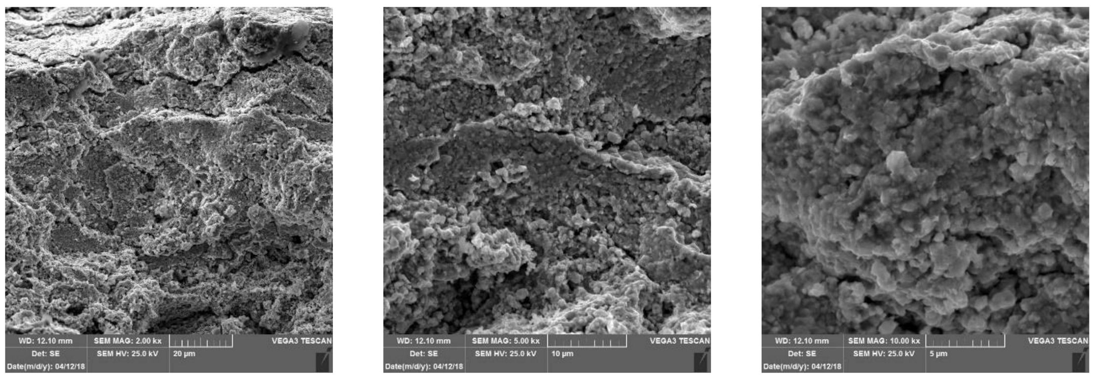
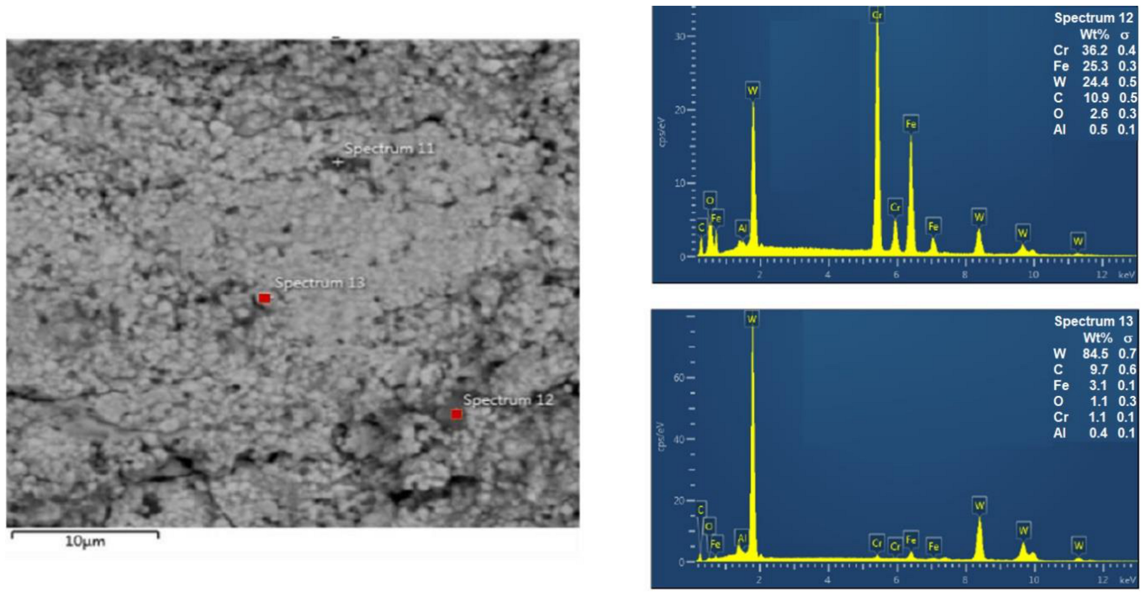
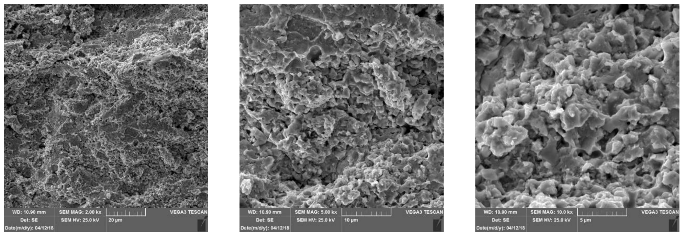
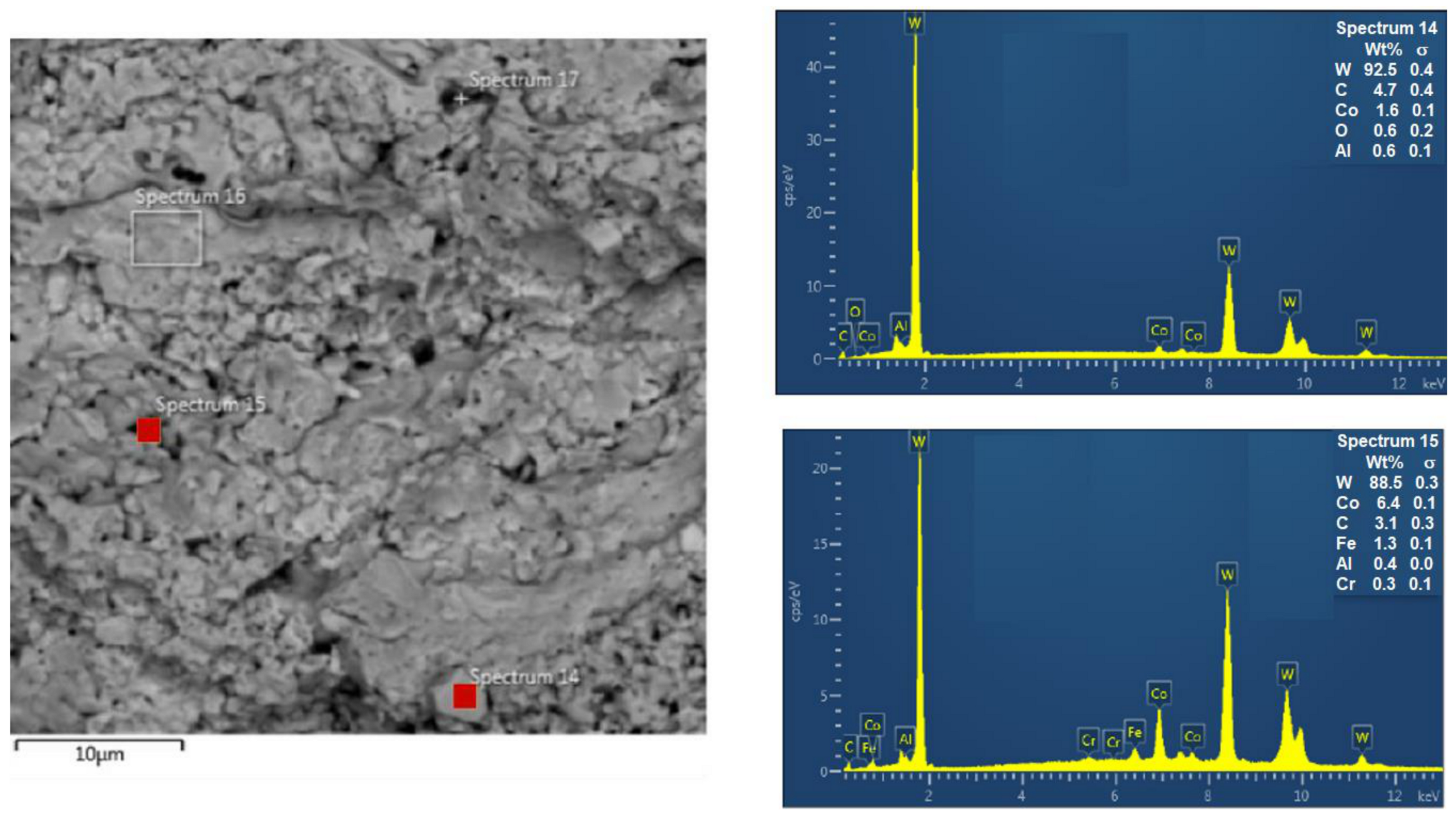
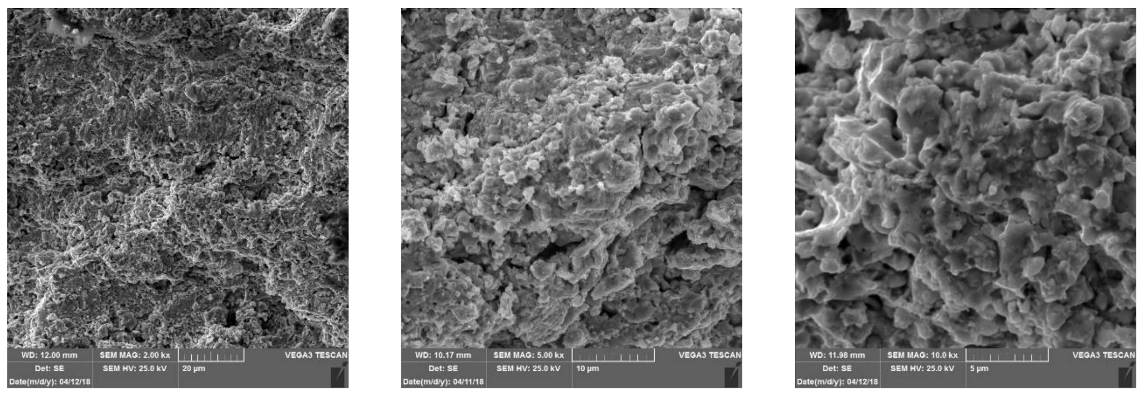
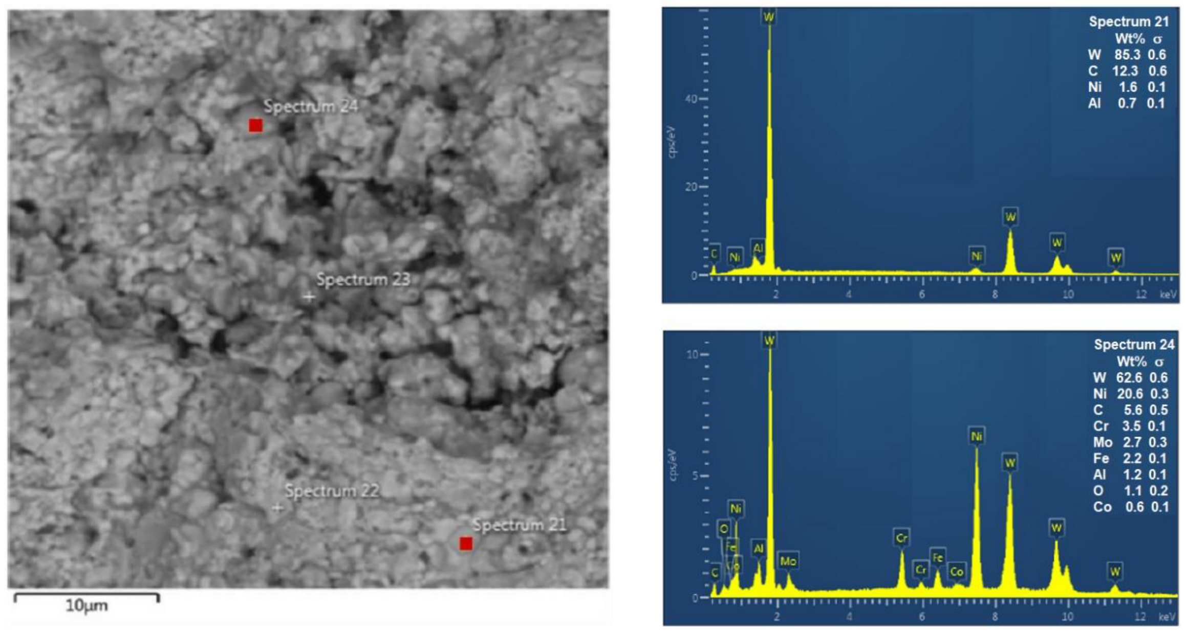
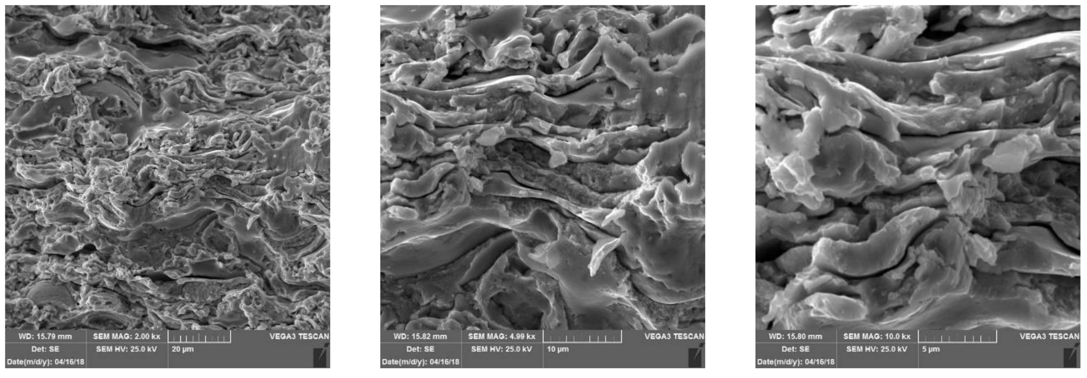
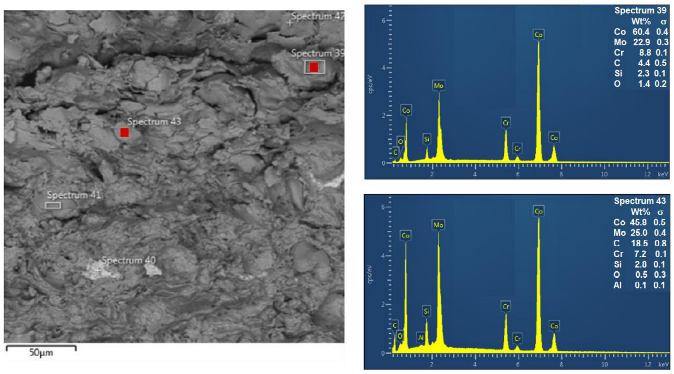
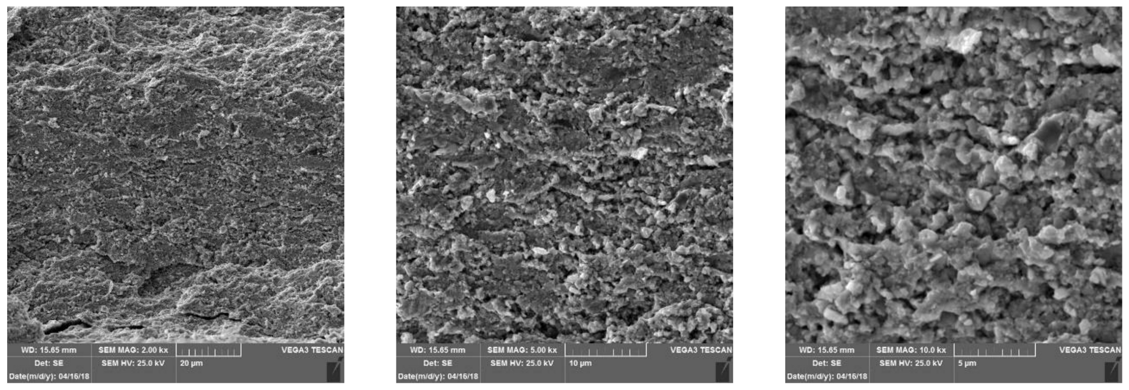
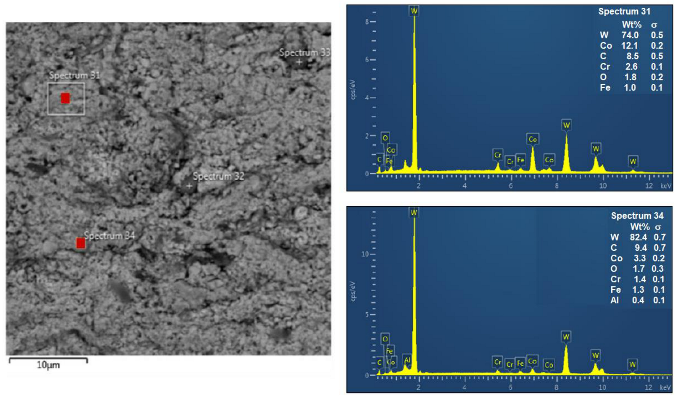
The microstructures of the coatings, as determined by their cross-sections, were dense, with no visible presence of pores and defects. The coatings were well-bonded to the substrate, being mechanically anchored in its micro-irregularities. In the case of cermet coatings, hard WC, as well as WB particles, were homogeneously dispersed in the matrix. In the alloy (hard carbide-free) coating, a typical sandwich structure was visible, with a significant deformation of splats forming at the moment of incidence on the surface, indicating a sufficient remelting of the powder. From a microscopic point of view, the structures of the evaluated coatings were not compact but, nevertheless, their properties were excellent and they can act as compact coatings under load.
-
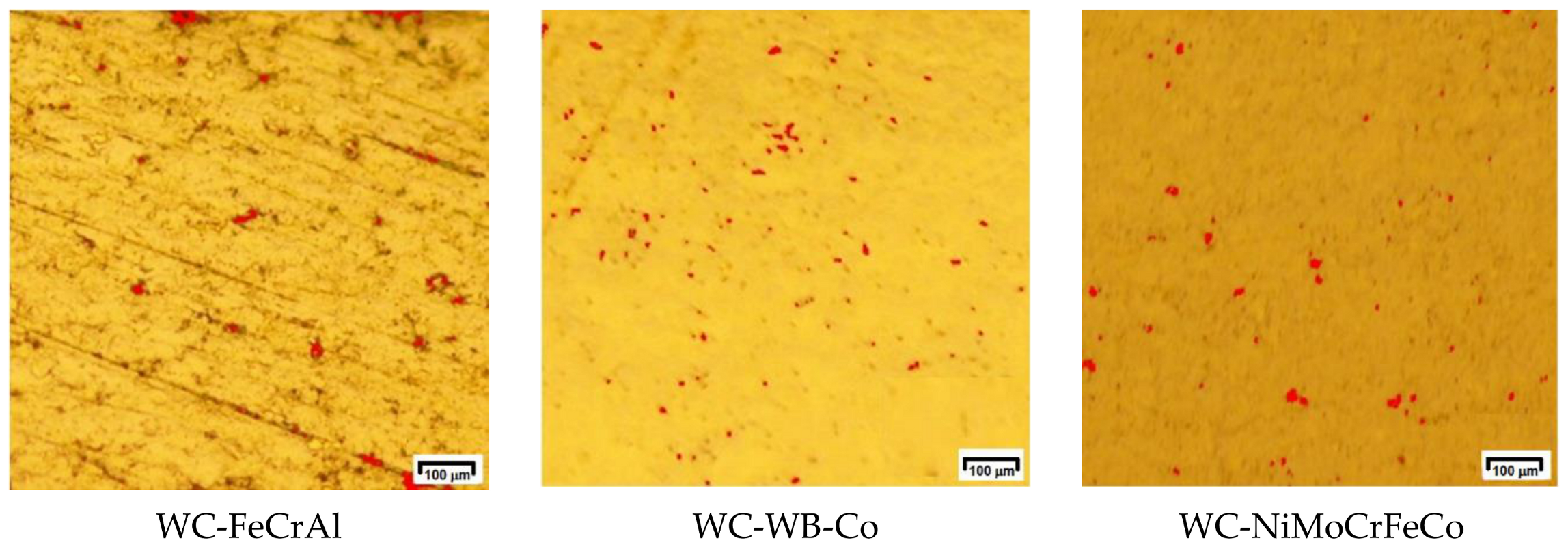
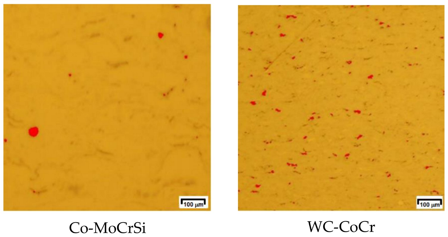
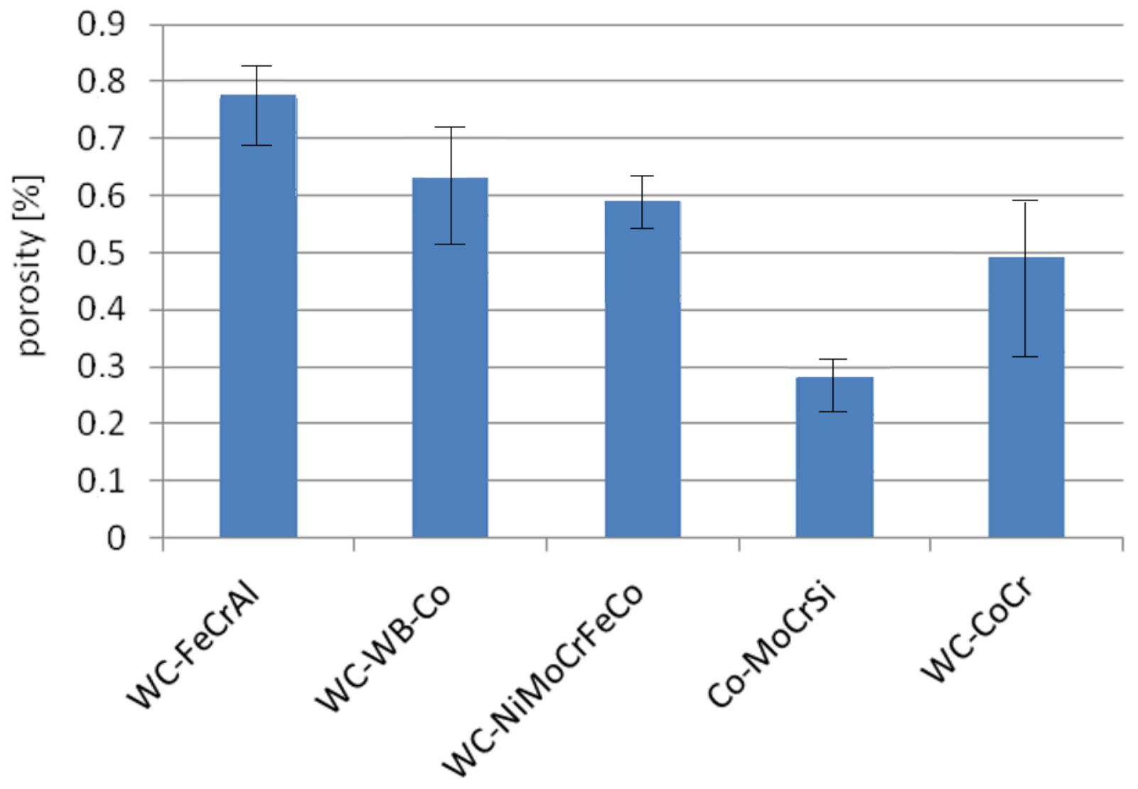
The highest hardness value was obtained by the WC-CoCr coating based on nanoparticles; while its porosity was the lowest within the group of coatings with WC particles. The lowest hardness value was achieved by the Co-MoCrSi alloy coating, which did not contain hard carbide particles. The highest occurrence of porosity was found in the WC-FeCrAl coating, which also had the lowest hardness value among the evaluated coatings containing WC particles. The lowest porosity of all evaluated coatings was obtained by the Co-MoCrSi alloy coating.
-
The resistance of coatings under erosive wear conditions was evaluated by the dry-pot wear test at two impact angles, 45° and 90°. Greater weight loss of the coatings was recorded at an impact angle of 90°. The lowest value of wear of all evaluated coatings was achieved by the coating with WC-CoCr nanoparticles for both impact angles. The Co-MoCrSi alloy coating achieved greater wear at an impact angle of 45° than at an impact angle of 90°, which could be caused by the grooving effect predominating at lower abrasive impact angles in relatively softer materials.
-
Higher wear was achieved among the evaluated coatings when using abrasive cloth with a larger number of grains per unit area and smaller dimensions, that is, with grit size # 120. Within the evaluated coatings, the lowest wear was achieved by the WC-CoCr nanocoat.
-
Based on the calculation of the indentation fracture toughness of the coatings, it was shown that the highest resistance to crack propagation was achieved by the WC-CoCr nanocoat.
The expanding family of HVOF-sprayed protective coatings has presented high potential for the transport industry, in order to meet the unique specifications from the viewpoint of the production of components (increased resistance to sliding wear, abrasion, adhesion, corrosion, erosion, galling, and thermal insulation), as well as with respect to their environmental impact (environmentally friendly coatings).

Author Contributions

Conceptualization, methodology, investigation, J.B. (Janette Brezinová), O.P., and P.M.; investigation, writing—review and editing, A.G. and D.D.; formal analysis, writing—review and editing, J.T. and F.P.; investigation, J.B. (Jakub Brezina) and K.Ľ. All authors have read and agreed to the published version of the manuscript.

Funding

This research was funded by the Ministry of Education, Science, Research and Sport of the Slovak Republic, VEGA 1/0497/20 and by Slovak Research and Development Agency, APVV-16-0359.

Acknowledgments

The authors are grateful to the Slovak Academy of Sciences for technical support.

Conflicts of Interest

The authors declare no conflict of interest.

References

  1. Espallargas, N. Future trends and applications of thermal spray coatings. In Future Development of Thermal Spray Coatings; Espallargas, N., Ed.; Elsevier Ltd.: Amsterdam, The Netherlands, 2015; pp. 10–13. [Google Scholar]
  2. Harder, B.J.; Zhu, D. Plasma Spray-Physical Vapour Deposition (PS-PVD) of Ceramics for Protective Coatings. In Advanced Ceramic Coatings and Materials for Extreme Environments: Ceramic Engineering and Science Proceedings, NASA Glenn Research Center, Cleveland OH 44135; John Wiley & Sons, Inc.: Hoboken, NJ, USA, 2011; Volume 32. [Google Scholar]
  3. Smith, G.M.; Resnick, M.; Flynn, K.; Dwivedi, G.; Sampat, S. Nature inspired, multi-functional, damage tolerant thermal spray coatings. Surf. Coat. Technol. 2016, 297, 43–50. [Google Scholar] [CrossRef] [Green Version]
  4. Tailor, S.; Modi, A.; Modi, S.C. High-Performance WC-based Coatings for Narrow and Complex Geometries. In Advanced Coating Materials; WILEY-Scrivener Publishing LLC: Salem, MA, USA, 2019; Chapter 6. [Google Scholar]
  5. Upadhyaya, R.; Tailor, S.; Shrivastava, S.; Modi, S.C. High performance thermal-sprayed WC-10Co-4Cr coatings in narrow and complex areas. Surf. Eng. 2017, 34, 412–421. [Google Scholar] [CrossRef]
  6. Bewilogua, K.; Bräuer, G.; Dietz, A.; Gäbler, J.; Goch, G.; Karpuschewski, B.; Szyszka, B. Surface technology for automotive engineering. CIRP Ann. Manuf. Technol. 2009, 58, 608–627. [Google Scholar] [CrossRef]
  7. Igartua, A.; Mendoza, G.; Fernandez, X.; Zabala, B.; Alberdi, A.; Bayon, R.; Aranzabe, A. Surface Treatments Solutions to Green Tribology. Coatings 2020, 10, 634. [Google Scholar] [CrossRef]
  8. Chattopadhyay, R. Green Tribology, Green Surface Engineering, and Global Warming; ASM International: Novelty, OH, USA, 2014; p. 336. [Google Scholar]
  9. Xu, B.; Zhang, W. Progress and application of nano-surface engineering in China. Novel Materials Processing by Advanced Electromagnetic Energy Sources. In Proceedings of the International Symposium on Novel Materials Processing by Advanced Electromagnetic Energy Sources, Osaka, Japan, 19–22 March 2004; pp. 339–343. [Google Scholar] [CrossRef]
  10. Tejero-Martin, D.; Rezvani Rad, M.; McDonald, A.; Hussain, T. Beyond Traditional Coatings: A Review on Thermal-Sprayed Functional and Smart Coatings. J. Therm. Spray Technol. 2019, 28, 598–644. [Google Scholar] [CrossRef] [Green Version]
  11. Shafique, M.; Luo, X. Nanotechnology in Transportation Vehicles: An Overview of Its Applications, Environmental, Health and Safety Concerns. Materials 2019, 12, 2493. [Google Scholar] [CrossRef] [Green Version]
  12. Guzanová, A.; Brezinová, J.; Draganovská, D.; Maruschak, P.O. Properties of coatings created by HVOF technology using micro-and nano-sized powder. Koroze Ochr. Mater. 2019, 63, 86–93. [Google Scholar] [CrossRef] [Green Version]
  13. Brezinová, J.; Guzanová, A.; Tkáčová, J. Determining the quality of renovation layers by using nano HVOF coatings. Mach. Technol. Mater. 2020, 14, 154–158. Available online: https://stumejournals.com/journals/mtm/2020/4/154.full.pdf (accessed on 5 August 2020).
  14. Lima, R.S.; Marple, B.R. Thermal Spray Coatings Engineered from Nanostructured Ceramic Agglomerated Powders for Structural, Thermal Barrier and Biomedical Applications: A Review. J. Therm. Spray Technol. 2007, 16, 40–63. [Google Scholar] [CrossRef] [Green Version]
  15. Matthäus, G.; Molnar, M. Advanced coating solutions, nanoHVOF-for the most demanding OD and ID applications with WC-CoCr 86 10 4 Thermico. Available online: https://www.slideshare.net/jonsebastianhenry/36877575-nano-hvofthermico11 (accessed on 2 November 2020).
  16. Makhlouf, A.S.H.; Tiginyanu, I. Nanocoatings and Ultra-Thin Films. In Technologies and Applications, 1st ed.; Woodhead Publishing Ltd.: Cambridge, UK, 2011; 448p. [Google Scholar]
  17. Killinger, A.; Gadow, R.; Mauer, G.; Guignard, A.; Vaßen, R.; Stöver, D. Review of New Developments in Suspension and Solution Precursor Thermal Spray Processes. J. Therm. Spray Technol. 2011, 20, 677–695. [Google Scholar] [CrossRef]
  18. Bai, M.; Kazi, H.; Zhang, X.; Liu, J.; Hussain, T. Robust Hydrophobic Surfaces from Suspension HVOF Thermal Sprayed Rare-Earth Oxide Ceramics Coatings. Sci. Rep. 2018, 8, 6973. [Google Scholar] [CrossRef] [PubMed] [Green Version]
  19. Bolelli, G.; Börner, T.; Bozza, F.; Cannillo, V.; Cirillo, G.; Lusvarghi, L. Cermet coatings with Fe-based matrix as alternative to WC–CoCr: Mechanical and tribological behaviours. Surf. Coat. Technol. 2012, 206, 4079–4094. [Google Scholar] [CrossRef]
  20. Aguero, A.; Camón, F.; García de Blas, J.; del Hoyo, J.C.; Muelas, R.; Santaballa, A.; Ulargui, S.; Vallés, P. HVOF-Deposited WCCoCr as Replacement for Hard Cr in Landing Gear Actuators. J. Therm. Spray Technol. 2010, 20, 1292–1309. [Google Scholar] [CrossRef]
  21. Brezinová, J.; Guzanová, A.; Draganovská, D.; Brezina, J. Characterization of selected properties of WC–WB–Co and WC–FeCrAl coatings applied by HVOF technology. Koroze Ochr. Mater. 2019, 63, 167–173. [Google Scholar] [CrossRef] [Green Version]
  22. Wang, H.; Yan, X.; Zhang, H.; Gee, M.; Zhao, C.; Liu, X.; Song, X. Oxidation-dominated wear behaviors of carbide-based cermets: A comparison between WC-WB-Co and Cr3C2-NiCr coatings. Ceram. Int. 2019, 45, 21293–21307. [Google Scholar] [CrossRef]
  23. Testa, V.; Morelli, S.; Bolelli, G.; Benedetti, B.; Puddu, P.; Sassatelli, P.; Lusvarghi, L. Alternative metallic matrices for WC-based HVOF coatings. Surf. Coat. Technol. 2020, 402, 126308. [Google Scholar] [CrossRef]
  24. Guzanová, A.; Brezinová, J.; Landová, M. Green carbides—innovation in thermal spraying coatings. Innovations 2018, 6, 68–71. [Google Scholar]
  25. AMPERIT®Thermal Spray Powders. Available online: www.hcstarck.com (accessed on 2 February 2020).
  26. Fisher, F.; Dvorak, M.; Siegmann, S. Development of Ultra-Thin Carbide Coatings for wear and Corrosion Resistance. In Proceedings of the International Thermal Spray Conference on new surfaces for a new millennium 2001 (Thermal spray 2001), Singapore, 28–30 May 2001; pp. 1131–1135. [Google Scholar]
  27. Wielage, B.; Wank, A.; Pokhmurska, H.; Grund, T.; Rupprecht, C.; Reisel, G.; Friesen, E. Development and trends in HVOF spraying technology. Surf. Coat. Technol. 2006, 201, 2032–2037. [Google Scholar] [CrossRef]
  28. Ghosh, G.; Sidpara, A.; Bandyopadhyay, P.P. Post-processing of HVOF sprayed WC-Co coating to enhance its performance. Encycl. Renew. Sustain. Mater. 2020, 1, 658–673. [Google Scholar] [CrossRef]
  29. Ghosh, G.; Sidpara, A.; Bandyopadhyay, P.P. High efficiency chemical assisted nanofinishing of HVOF sprayed WC-Co coating. Surf. Coat. Technol. 2018, 334, 204–214. [Google Scholar] [CrossRef]
  30. Panziera, R.C.; Costa de Oliveira, A.C.; Pereira, M.; Ratszunei, F. Study of the effects of the laser remelting process on the microstructure and properties of the WC–10Co–4Cr coating sprayed by HVOF. J. Brazil. Soc. Mech. Sci. Eng. 2020, 42, 119. [Google Scholar] [CrossRef]
  31. Zdravecká, E.; Ondáč, M.; Tkáčová, J. Tribological Behavior of Thermally Sprayed Coatings with Different Chemical Composition and Modified by Remelting. Tribol. Ind. 2019, 41, 463–470. [Google Scholar] [CrossRef]
  32. La Rosa, M. Cost-efficient advanced coating solutions. German Mongolian Corporate Days 2015, Ulaanbaatar, 13 October 2015. Available online: https://www.researchgate.net/publication/283421041 (accessed on 2 November 2020).
  33. Sampath, S.; Srinivasan, V.; Valarezo, A.; Vaidya, A.; Streibl, T. Sensing, control, and in situ measurement of coating properties: An integrated approach toward establishing process-property correlations. J. Therm. Spray Technol. 2009, 18, 243–255. [Google Scholar] [CrossRef]
  34. Ang, A.; Sanpo, N.; Sesso, M.L.; Kim, S.Y.; Berndt, C. Thermal Spray Maps: Material Genomics of Processing Technologies. J. Therm. Spray Technol. 2013, 22, 1170–1183. [Google Scholar] [CrossRef]
  35. Vaidya, A.; Streibl, T.; Li, L.; Sampath, S.; Kovarik, O.; Greenlaw, R. An integrated study of thermal spray process-structure-property correlations: A case study for plasma sprayed molybdenum coatings. Mater. Sci. Eng. A 2005, 403, 191–204. [Google Scholar] [CrossRef]
  36. Oksa, M.; Turunen, E.; Suhonen, T.; Varis, T.; Hannula, S.P. Optimization and Characterization of High Velocity Oxy-fuel Sprayed Coatings: Techniques, Materials, and Applications. Coatings 2011, 1, 17–52. [Google Scholar] [CrossRef] [Green Version]
  37. Valarezo, A.; Choi, W.B.; Chi, W.; Gouldstone, A.; Sampath, S. Process control and characterization of NiCr coatings by HVOF-DJ2700 system: A process map approach. J. Therm. Spray Technol. 2010, 19, 852–865. [Google Scholar] [CrossRef]
  38. Turunen, E.; Varis, T.; Hannula, S.P.; Vaidya, A.; Kulkarni, A.; Gutleber, J.; Sampath, S.; Herman, H. On the role of particle state and deposition procedure on mechanical, tribological and dielectric response of high velocity oxy-fuel sprayed alumina coatings. Mater. Sci. Eng. A 2006, 415, 1–11. [Google Scholar] [CrossRef]
  39. Surface Technology. Available online: http://www.surfacetechnology.co.uk/automotive-surface-coatings/ (accessed on 7 July 2020).
  40. Picas, J.A.; Forn, A.; Rilla, R.; Martin, E. HVOF thermal sprayed coatings on aluminium alloys and aluminium matrix composites. Sur. Coat. Technol. 2005, 200, 1178–1181. [Google Scholar] [CrossRef]
  41. Uzun, A.; Altuncu, E.; Ustel, F.; Türk, A.; Ozturk, S. Investigation of wear behaviour of HVOF sprayed WC-Co coatings for automotive parts in different working conditions. Int. J. Surf. Sci. Eng. 2011, 5, 180–192. [Google Scholar] [CrossRef]
  42. High Velocity Oxy-Fuel (HVOF) Solutions. Sulzer Metco. Available online: https://www.upc.edu/sct/en/documents_equipament/d_323_id-804-1.pdf (accessed on 14 September 2020).
  43. Shetty, D.K.; Wright, I.G.; Mincer, P.N.; Clauer, A.H. Indentation fracture of WC-Co cermets. J. Mater. Sci. 1985, 20, 1873–1882. [Google Scholar] [CrossRef]
  44. Houdková, Š.; Kašparová, M. Experimental study of indentation fracture toughness in HVOF sprayed hardmetal coatings. Eng. Fract. Mech. 2013, 110, 468–476. [Google Scholar] [CrossRef]
  45. Feng, Y.; Zhang, T. Determination of fracture toughness of brittle materials by indentation. Acta Mech. Solida Sin. 2015, 28, 221–234. [Google Scholar] [CrossRef]
  46. Ponton, C.B.; Rawlings, R.D. Vickers indentation fracture toughness test Part 1: Review of literature and formulation of standardised indentation toughness equations. Mater. Sci. Technol. 1989, 5, 865–872. [Google Scholar] [CrossRef]
  47. Chicot, D.; Pertuz, A.; Roudet, F.; Staia, M.H.; Lesage, J. New developments for fracture toughness determination by Vickers indentation. Mater. Sci. Technol. 1985, 20, 877–884. [Google Scholar] [CrossRef]
  48. Lawn, B.R.; Swain, M.V. Microfracture beneath Point Indentations in Brittle Solids. J. Mater. Sci. 1975, 10, 113–122. [Google Scholar] [CrossRef]
  49. Lawn, B.R.; Fuller, E.R. Equilibrium penny-like cracks in indentation fracture. J. Mater. Sci. 1975, 10, 2016–2024. [Google Scholar] [CrossRef]
  50. Evans, A.G.; Wilshaw, T.R. Quasi-static solid particle damage in brittle solids—I. Observations analysis and implications. Acta Metall. 1976, 24, 939–956. [Google Scholar] [CrossRef]
  51. Evans, A.G.; Charles, E.A. Fracture Toughness Determinations by Indentation. J. Am. Ceram. Soc. 1976, 59, 371–372. [Google Scholar] [CrossRef]
  52. Shibe, V.; Chawla, V. Erosion Studies of D-Gun-Sprayed WC-12%Co, Cr3C2-25%NiCr and Al2O3-13%TiO2 Coatings on ASTM A36 Steel. J. Therm. Spray Tech. 2019, 59, 2015–2028. [Google Scholar] [CrossRef]
  53. Somasundaram, B.; Jegadeeswaran, N.; Madhu, G.; Ramesh, M.R. Erosion behaviour of HVOF sprayed (Cr3C2-35%NiCr) + 5%Si coatings. IJMET 2017, 8, 1124–1134. [Google Scholar]
  54. Ding, X.; Cheng, X.D.; Yuan, C.Q.; Shi, J.; Ding, Z.X. Structure of Micro-nano WC-10Co4Cr Coating and Cavitation Erosion Resistance in NaCl Solution. Chin. J. Mech. Eng. 2017, 30, 1239–1247. [Google Scholar] [CrossRef] [Green Version]
  55. Geng, Y.; Konovalov, S.V.; Chen, X. Research status and application of the high-entropy and traditional alloys fabricated via the laser cladding. Prog. Phys. Met. 2020, 21, 26–45. [Google Scholar] [CrossRef]
  56. Hutsaylyuk, V.; Student, M.; Dovhunyk, V.; Posuvailo, V.; Student, O.; Maruschak, P.; Koval’chuck, I. Effect of hydrogen on the wear resistance of steels upon contact with plasma electrolytic oxidation layers synthesized on aluminum alloys. Metals 2019, 9, 280. [Google Scholar] [CrossRef] [Green Version]
Figure 1. SEM micrographs of powders used.
Metals 10 01675 g001aMetals 10 01675 g001b
Figure 2. (a) Fixing of test samples in the testing device and (b) scheme of contact geometry.
Metals 10 01675 g002
Figure 3. Scheme of test device for abrasive resistance test using abrasive cloth.
Metals 10 01675 g003
Figure 4. Basic types of cracks.
Metals 10 01675 g004
Figure 5. Microstructures of coating cross-sections; SEM.
Metals 10 01675 g005aMetals 10 01675 g005b
Figure 6. Microstructure of the WC-FeCrAl coating at different magnifications.
Metals 10 01675 g006
Figure 7. Chemical analysis of the WC-FeCrAl coating.
Metals 10 01675 g007
Figure 8. Microstructure of the WC-WB-Co coating at different magnifications.
Metals 10 01675 g008
Figure 9. Chemical analysis of the WC-WB-Co coating.
Metals 10 01675 g009
Figure 10. Microstructure of the WC-NiMoCrFeCo coating at different magnifications.
Metals 10 01675 g010
Figure 11. Chemical analysis of the WC-NiMoCrFeCo coating.
Metals 10 01675 g011
Figure 12. Microstructure of the Co-MoCrSi coating at different magnifications.
Metals 10 01675 g012
Figure 13. Chemical analysis of the Co-MoCrSi coating.
Metals 10 01675 g013
Figure 14. Microstructure of the WC-CoCr coating at different magnifications.
Metals 10 01675 g014
Figure 15. Chemical analysis of the WC-CoCr coating.
Metals 10 01675 g015
Figure 16. Occurrence of pores in evaluated coatings (marked red).
Metals 10 01675 g016aMetals 10 01675 g016b
Figure 17. Porosity found in coatings.
Metals 10 01675 g017
Figure 18. The results of HV 0.1 measurements.
Metals 10 01675 g018
Figure 19. Mass loss of coatings in dry pot wear test at two impact angles.
Metals 10 01675 g019
Figure 20. Mass loss of coatings in abrasive wear test with abrasive cloth.
Metals 10 01675 g020
Figure 21. Indentation fracture toughness, KIc, of coatings.
Metals 10 01675 g021
Table 1. Summary of coatings for different applications [1].
Utilization of CoatingsAerospaceAutomobileIndustrial Gas TurbinesMaritime
Thermal barrier coatings
ZrO2-Y2O3 (YSZ)

ZrO2-25CeO2-Y2O3
CeO2-YSZ
CaTiO3


MCrAlY (M=Co, Ni)
Turbine components


Bond coats
Piston crowns, cylinder heads, valves, exhaust ports, manifolds, turbochargers, backing plates of brakes

Bond coat
Combustor liner, transition rings, splash plate, and fuel injector


Bond coat
Seals/abradables
Ni-graphite

MCrAlY (M=Co, Ni)

Polyesters
NiAl-polyesters
Al, bronze, babbitt
AlSi with polyester, polyimide or BN
Rotating vane assemblies of aircraft turbines Compressor case

Compressor case


Compressor case
Oxidation and corrosion resistance
MCrAlY (M=Co, Ni)

Hastelloy (NiCrMo)
Tribaloys (Co-Cr-Si-Mo)

Al

Zn, Zn-Al
Engine components


Exhaust systems
Compressor section carrying moisture and chlorides and parts of the turbine in contact with fuelsNon-sacrificial thermal spray coatings


Cathodic protection
Wear resistance and repair
WC-Co, WC-CoCr and WC-Ni


Ni-Al, CuNiIn


Cr3C2-NiCr


Triballoys
(Co-Cr-Si-Mo),
NiCr,NiCrMo, NiMoAl,
alloy 625 and 718
Mo
Hydraulic systems, rebuilding/repair of worn or corroded components
Bond coats, anti-fretting, and clearance control
Seals at high temperature
Prevention of galling in cylinder liners


Rebuilding of crankshaft

Drop erosion in pistons
Galling in cylinder liners
Rotating shafts


High-temperature parts of the turbine section
Compressor

Build-up and repair
Erosion–corrosion of water turbines
Table 2. Common High Velocity Oxy-Fuel (HVOF) surface applications in transport industries [43].
Common HVOF Surface Applications in Transport Industry
Aviation Turbine engine fan blade mid-spans, compressor blades, turbine blade roots, bearing journals, stator and rotor disk snap diameters, landing gears, actuators, flap tracks, helicopter rotor joint´s and sleeves
Automotive Transmission shifter forks
Transportation/Heavy Equipment Hydraulic rods, pistons, ship steering rams
Table 3. Chemical composition of base material (wt. %).
Base MaterialCSiMnPSCrMoNiFe
1.4404 0.03120.40.0316.5–18.52–2.511–14Balance
Table 4. Chemical composition of feedstock powders (wt. %).
ElementsWC-FeCrAlWC-WB-CoWC-NiMoCrFeCoCo-MoCrSiWC-CoCr
C5.4–5.93.5–4.05–5.6-4.8–5.6
Fe10–12-0.8–1.5--
Cr2.5–3.8-2–3.58.53.4–4.6
Al0.6–1.2----
B-1.5–2.5---
Co-9–110.3–0.6Bal.8.5–11.5
WBal.Bal.Bal.-Bal.
Ni--10–12.5--
Mo--2–3.528.5-
O--max. 2.5--
Si---2.6-
Fe----0.2
Table 5. Spraying parameters.
ParameterValue
Nozzle diameter25.4 mm
Kerosene flow6.0 g·h−1/22.7 L·h−1
Oxygen flow800 L·min−1
Stand-off distance380 mm
Powder flow rate80 g·min−1
Publisher’s Note: MDPI stays neutral with regard to jurisdictional claims in published maps and institutional affiliations.

