Article

Study of the Combined Severe Plastic Deformation Techniques Applied to Produce Contact Wire for High-Speed Railway Lines

by
Rashid N. Asfandiyarov
1,2,*,
Georgy I. Raab
1 and
Denis A. Aksenov
1,2
1
Institute of Physics of Advanced Materials, Ufa State Aviation Technical University, 12 K. Marx St., 450008 Ufa, Republic of Bashkortostan, Russia
2
Institute of Molecule and Crystal Physics UFRC RAS, 151 pr. Oktyabrya, 450075 Ufa, Republic of Bashkortostan, Russia
*
Author to whom correspondence should be addressed.
Metals 2020, 10(11), 1476; https://doi.org/10.3390/met10111476
Submission received: 28 September 2020 / Revised: 25 October 2020 / Accepted: 2 November 2020 / Published: 5 November 2020
(This article belongs to the Special Issue Application of Alloys in Transport)

Abstract

:
This work considers the development and the application of combined severe plastic deformation (SPD) techniques to produce contact wire with an enhanced complex of physical, mechanical, and service properties used for high-speed railway lines. This type of processing can be used as an alternative to most conventional production methods, including rolling and drawing. The proposed technique is based on the combination of radial swaging and equal-channel angular pressing, bundled with the wire-forming process. Laboratory contact wire samples with an enhanced complex of physical, mechanical, and service properties were produced during physical experiments. The composition of processed alloy samples meets modern requirements for contact wires for high-speed railways. Ultimate tensile strength of 560 ± 20 MPa, electrical conductivity of 76 ± 2% IACS, and relative tensile elongation of 20 ± 2% are achieved through the formation of a band structure. Fragments of 300 ± 20 nm were formed inside strips with the precipitation of secondary phase particles of 20–100 nm along the fragment boundaries, mainly during the aging process.

Graphical Abstract

1. Introduction

The most common method for producing contact wires [1,2,3] is combined processing, including several separate technological processes: continuous casting and rolling to obtain wire rod, drawing or rolling of wire rod to form a profile, and a finishing hardening heat treatment [4,5,6,7,8,9,10]. Recently, drawing or rolling operations have been replaced by the continuous pressing of wire rods on extruders according to the traditional Conform scheme, which provides economic advantages due to the quick changeover of the line, reduction in production areas, and the range of equipment when receiving contact wires [11,12,13,14,15,16,17]. As an alternative to the combined approaches, continuous methods for producing products with a finite geometry, from the stage of continuous casting to the stage of product forming, can be used, applying modern methods of deformation processing such as SPD, for example [18,19,20,21,22]. The most promising applications for obtaining long products can be quite productive SPD processes with alternating forging (radial) and/or the method of equal channel angular pressing according to the Conform scheme (ECAP-C). In this regard, in this paper, we propose and study a method for continuously producing a contact wire under conditions of continuous casting of a billet, its crystallisation, and forming, using alternating (radial) forging and ECAP-C methods. One should take into account that the use of large deformations during SPD also leads to large thermal effects from deformation.

2. Materials and Methods
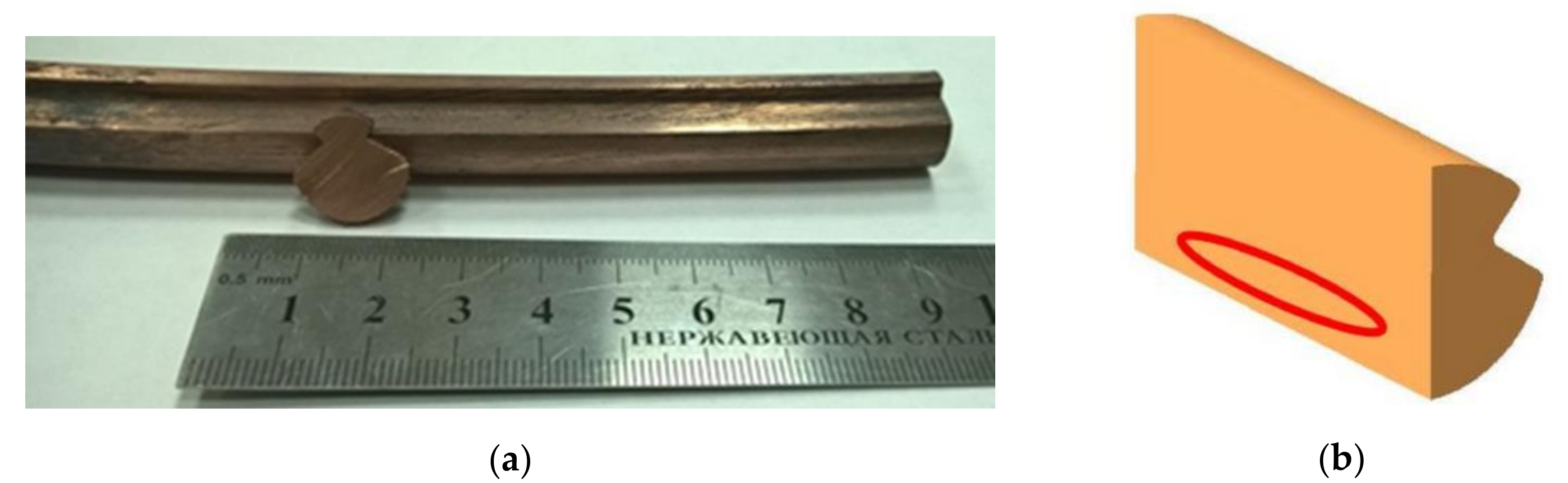
An important difference between the developed technology and the existing solutions is the fixation of a solid solution by cooling in water, from a temperature of at least 1000 °C, after crystallization of the workpiece. The deformation processing consists of two alternating radial swagings (forgings) with a true accumulated strain of e~1.5 at a final temperature of 300 °C, and ECAP-C with the forming of the wire at the temperature of the initial billet, 300 °C, and a noticeable increase from subsequent deformation heating. The total calculated true cumulative deformation at treatment was e~4. Of greatest interest and complexity for analysis is the ECAP-C operation combined with extrusion, considering precisely the factor of the mutual influence of the existing deformation conditions on the formation properties.

2.1. Material

A heat-hardenable low-alloyed Cu-0.65%Cr, which is widely used in electrical engineering, was selected as the research material. This alloy was subjected to high-temperature treatment at 1000 °C for 1 h in a Nabertherm L15/11 furnace (Nabertherm GmbH, Lilienthal, Germany). As a result, a coarse-grained structure with an average grain size of 140 ± 3 μm was obtained. In a state of supersaturated solid solution, Cu-0.65%Cr alloy has the following physical and mechanical characteristics: tensile strength 240 ± 10 MPa, electrical conductivity 45% IACS, tensile elongation 40%.

2.2. Computer Simulation

To study the stress–strain state (SSS), finite element computer modelling in the Deform 3D environment was used. The rheological characteristics of the material were taken from the literature and the Deform 3D database. The workpiece was a plastic body. The dimensions of the rectangular cross-section of the original billet were 26 mm × 26 mm. After processing, the profile of the shaped contact wire was like that for high-speed rail with a nominal area of 150 mm2 [23].
The number of finite elements was 50,000 (tetrahedrons). The stamping tool was an absolutely rigid body. The angular speed of rotation of the wheel was chosen as constant and equal to 1 rad/s (10 rpm). The simulation was performed considering the increase in metal temperature due to the thermal effect of the deformation. The heat transfer coefficient of the punch tool with the workpiece was taken to be 5000 W/m2·°C. The temperature of the instrument during modeling was constant and amounted to 300 °C. The friction factor was taken to be equal to f = 0.4, between the wheel and the workpiece, and f = 0.2, between the workpiece and the rest of the tooling elements [24].

2.3. Structural Studies

Modern techniques and metallographic examination devices (Olympus GX51F, Olympus Corporation, Tokyo, Japan), as well as scanning electron microscope (SEM, Jeol JSM-6390, JEOL Ltd., Tokyo, JAPAN), were applied for analysis of the structure of the processed samples.
Scanning electron microscopy with electron back scatter diffraction (EBSD) was performed employing a field emission microscope TESCAN MIRA 3 LMH (TESCAN ORSAY HOLDING a.s., Brno, Czech Republic) equipped with the Oxford Instruments HKL Channel 5 system (Oxford Instruments, Abingdon, UK) with a scanning step of 0.4 microns. Maps of misorientation of grains were constructed, the size of grains and subgrains was estimated, and quantitative analysis of low and high angle boundaries was carried out.
Foils with a thickness of 10–11 microns were prepared for microstructural studies. Electrochemical polishing was carried out using a TenuPol 5 setup (Struers Inc., Detroit Rd. Westlake Cleveland, USA). The analysis of the structure was carried out on a Jeol JEM 2100 transmission microscope (JEOL Ltd., Tokyo, JAPAN) at an accelerating voltage of 200 kV in bright and dark fields.
Diffraction patterns for X-ray analysis were obtained using a Rigaku Ultima IV (RIGAKU CORPORATION, Tokyo, JAPAN) by the Bragg-Brentano pattern with the application of Cu Kα radiation, generated at a voltage of 40 kV and a current of 40 mA. A graphite monochromator was placed in front of the detector. X-ray patterns were obtained within the range from 35° to 145° in the continuous scanning regime with a rate of 0.25°/s.
The lattice parameter, CSR size distribution, edge and screw dislocation density, and effective dislocation radius were calculated by analyzing diffraction patterns within the WPPM approach implemented in the PM2K program [25].

2.4. Study of Physical Mechanical Properties

Static tensile tests were performed to study the mechanical characteristics of the contact wire samples made from Cu-0.65%Cr, using an Instron 5982 (Instron, Norwood, MA, USA). At least 3 samples were investigated for each condition to be studied.
Electrical conductivity (EC) was determined using a VE-27NC eddy-current meter (Sigma LLC, Ekaterinburg, Russia), converting the obtained values to IACS (International Annealed Copper Standard).

3. Research Results and Discussion

Following the radial swaging, a billet up to 350 mm in length and with a cross-section of 24 mm × 24 mm (Figure 1) was processed from an initial cast bar.
Structural analysis at the mesoscale showed that during radial pressing, a fragmented structure with shear bands (longitudinal section) was formed in the workpiece. The mean cross dimension of the bands was 50 ± 3 µm (Figure 2). The ultimate tensile strength upon the radial swaging was 365 ± 10 MPa, with a relative tensile elongation of 17 ± 2% and an electrical conductivity of 33 ± 2% IACS.
Below, we present the findings of the research of the ECAP combined with the wire forming and final thermal treatment, i.e., ageing.

3.1. Computer Simulation of ECAP-C Processes

Figure 3a shows the strain distribution fields in the billet during ECAP-C combined with the wire forming. The accumulated strain in the wire averages ~5 with the highest level observed in the peripheral areas.
Figure 3b demonstrates the mean stress fields in the deformation region formed during ECAP-C combined with the wire forming. The computer simulation findings show that compressive stress prevails in the deformation region.
It is a well-known fact that the ageing temperature of chromium bronze is within 450–500 °C [19,20,21,22], which places certain limitations on treatment processes.
ECAP-C with the wire forming is associated with a notable heat formation. The deformation zone has an inhomogeneous temperature, which reaches 600 °C in the peripheral zone at a steady state. At the same time, the wire billet temperature does not exceed 500 °C when exiting the deformation zone (Figure 3c).
Thus, the performed computer simulation shows the feasibility of this technological approach from the point of view of deformation processing and principles of SPD.

3.2. Physical Experiment

Figure 4 shows the laboratory sample processed during a physical experiment.

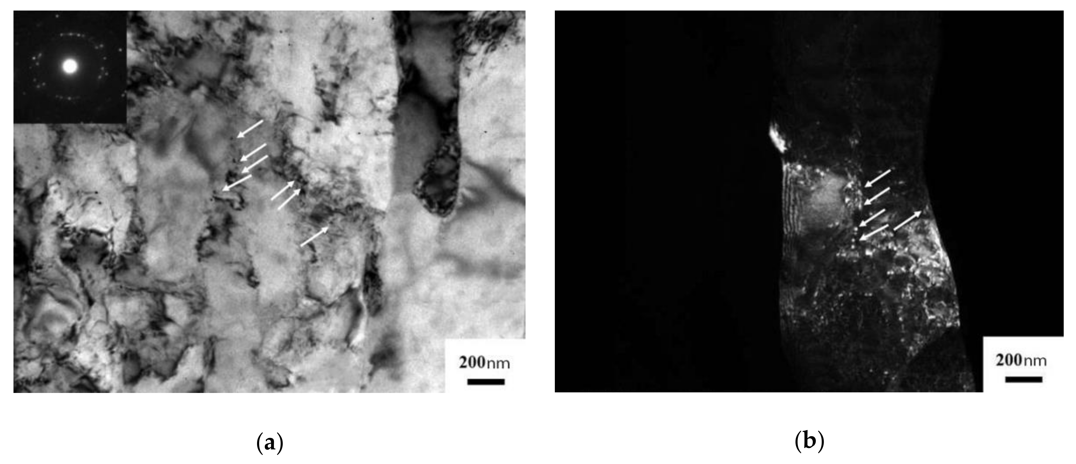
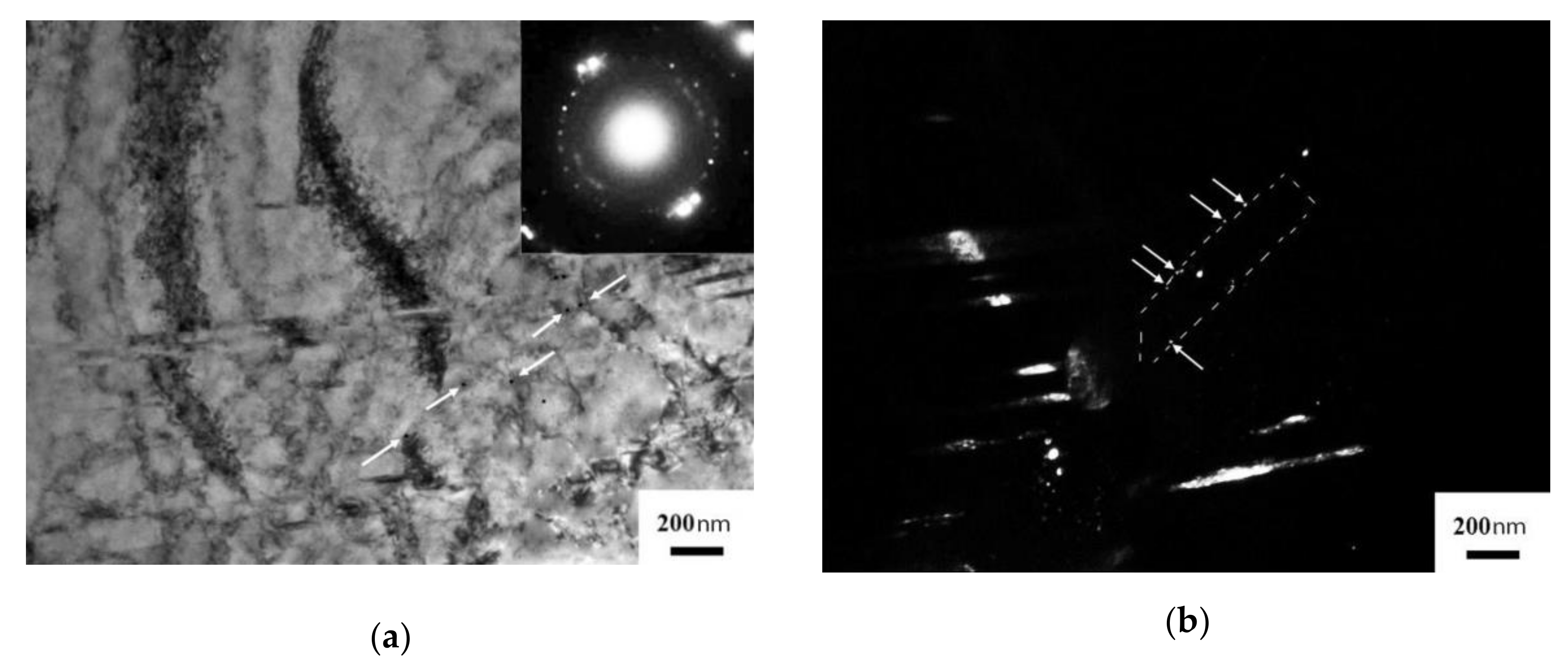
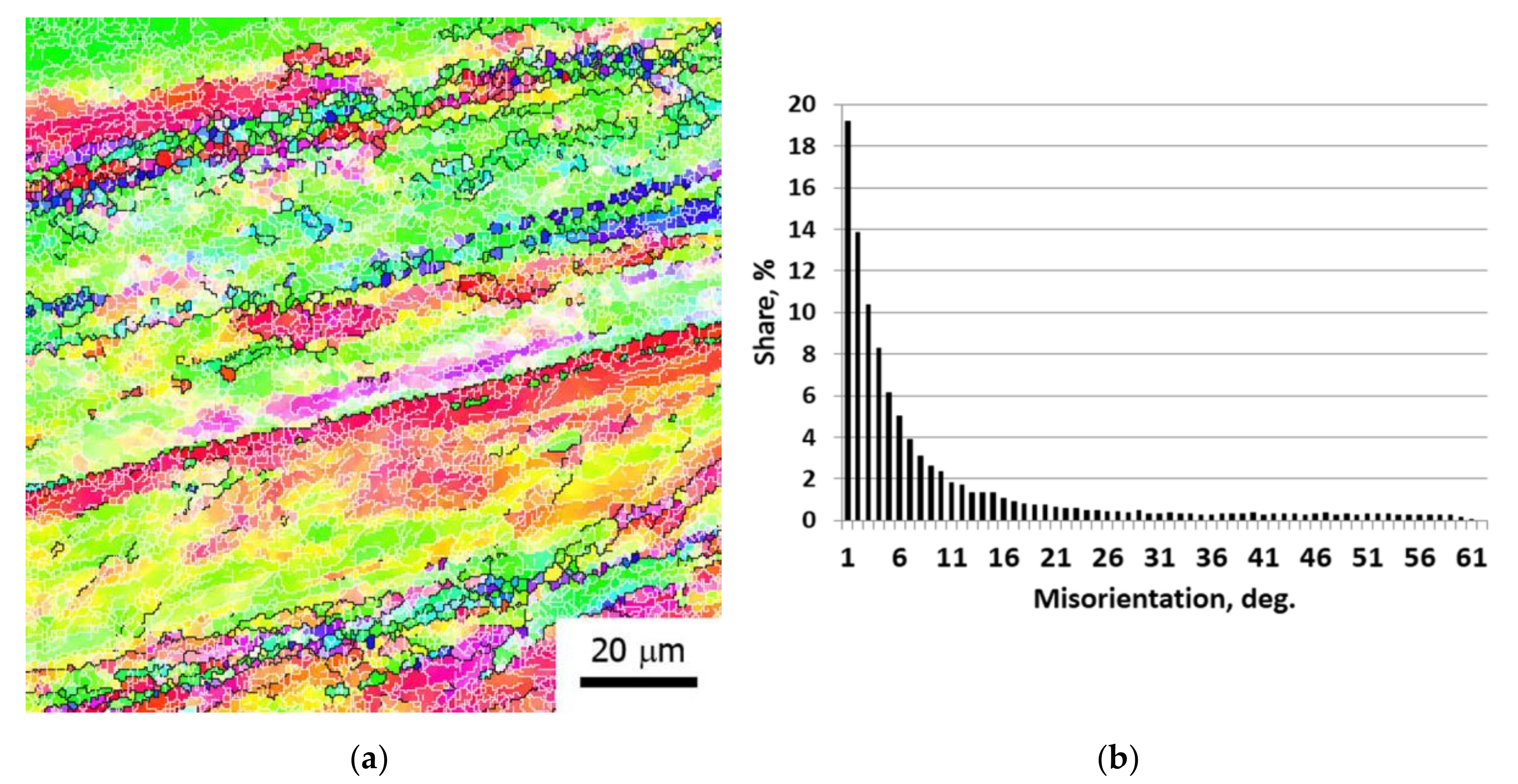
3.2.1. Microstructural Analysis

TEM microstructure analysis revealed the formation of a band structure (Figure 5) with the size of fragments inside the bands of 300 ± 20 nm, and the precipitation of secondary strengthening particles, with an average size of 20 ± 2 nm, mainly along the boundaries. The distance between the centers of the particles was 160 ± 15 nm.
After ECAP with wire forming, the samples were heat treated (ageing) [21,22,23,26]. Ageing was performed at 450 °C, with a holding time of 1 h and further air cooling.
Upon ageing (Figure 6), the mean fragment size increased up to 360 ± 17 nm. Diffraction contrasts were observed at band boundaries, which points to the occurrence of relaxation of the boundary areas during ageing. Well-developed dislocation networks are preserved with fixed secondary phase particles. The precipitated particles have the size of 30 ± 3 nm, which agrees well with the data on the ageing of ultrafine-grained chromium bronze [19,20,22]. The average distance between the centers of the particles decreased to 110 ± 10 nm, which indicates an increase in the density of the arrangement of particles in the material.
Analysis of the misorientation map (EBSD) (Figure 7) of the Cu-0.65%Cr alloy after the final treatment with ECAP-C with wire forming and subsequent aging at 450 °C for 1 h indicates the formation of structural regions bounded by elongated high-angle boundaries (black lines, > 15°), which can be characterized as stripes. A developed substructure is observed inside the stripes, characterized by a network of low-angle boundaries (white lines, < 15°), the proportion of which is 80%. At the border of the stripes, a microtexture is observed in the (001) direction. In addition, there are microsections bounded by high-angle boundaries and lined up along high-angle boundaries of stripes. The grain (areas bounded by black lines) and subgrain (areas bounded by white lines) size obtained using the EBSD method were 1.7 ± 0.1 and 3.2 ± 0.6 μm, respectively. The smaller grain size in comparison with the subgrain is associated with structural features. The main contribution to the quantitative analysis of grains is made by microsections of the structure limited by high-angle boundaries, which were most likely formed in the process of dynamic recrystallization, since the temperature of deformation processing exceeded 600 °C.

3.2.2. X-ray Structural Analysis

Table 1 (near here) presents the results of the X-ray structure analysis. The coherent scattering region (CSR) was 220 ± 12 nm in the initial state. The value of the lattice parameter indicates that a supersaturated solid solution is present in this state.
ECAP with wire forming resulted in the reduction in the CSR. The lattice parameter decreased, which points to the strain-induced decay of the supersaturated solid solution. The dislocation density reaches the value of 2.65 ± 0.04 × 10¹⁴ m−2.
In the process of aging, two main processes are realized: relaxation of stresses—a decrease in the density of dislocations in the material and decomposition of a supersaturated solid solution. Despite the fact that fine particles formed during the decomposition of the solid solution are effective stoppers for the movement of dislocations, we observe a decrease in the value of the dislocation density after aging to 1.65 ± 0.02 × 10¹⁴ m−2. CSR increases, which can be associated with the transition of boundaries to a steady-state. The lattice parameter also decreases, testifying to the thermally stimulated decay of the solid solution of the alloying elements in the Cu matrix.

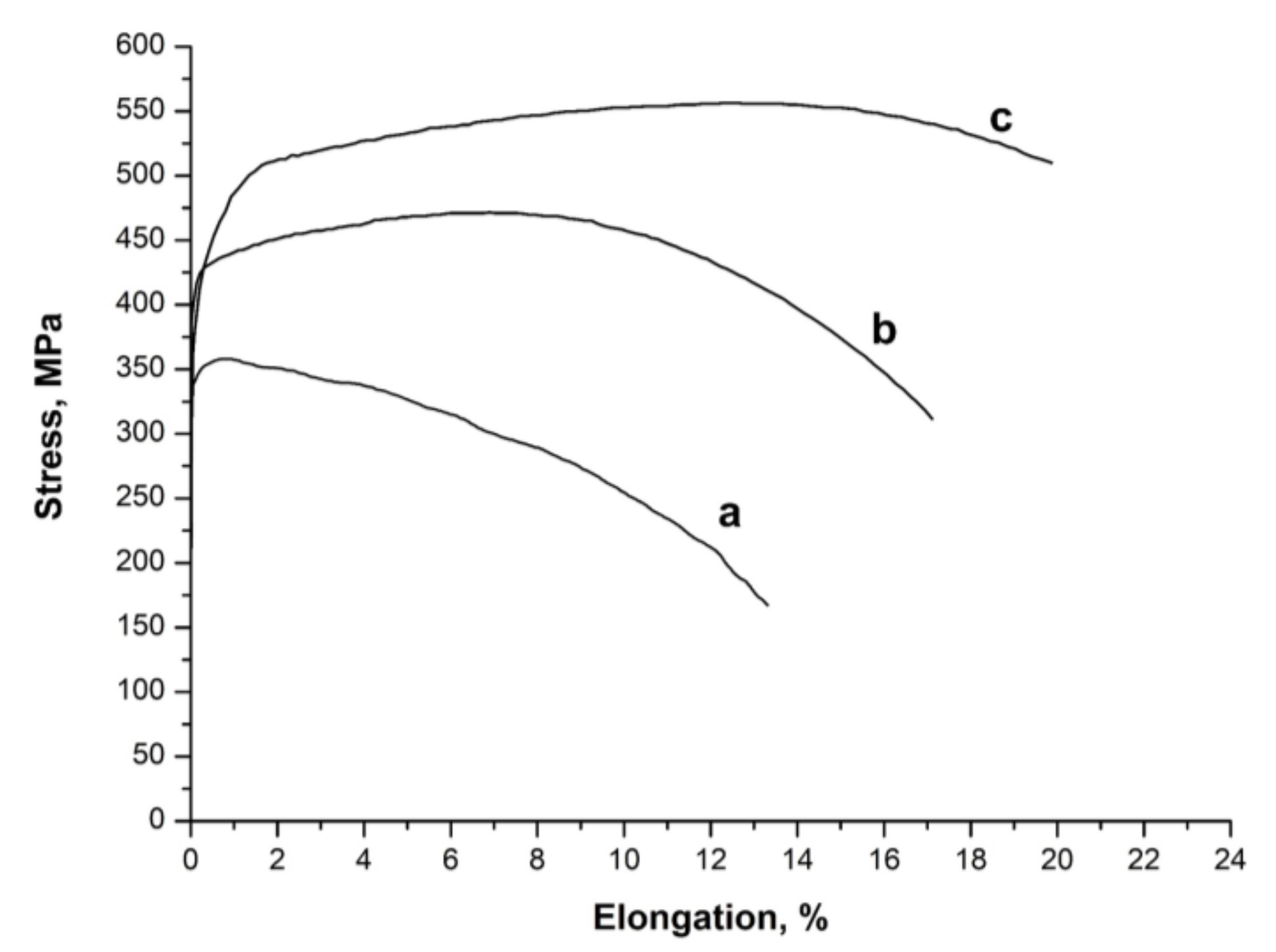
3.2.3. Physical Mechanical Properties

The tensile strength of the Cu-0.65%Cr alloy after forging was 365 ± 10 MPa (Figure 8). The conductivity at the forging stage was maintained at 33% IACS. One cycle of ECAP with wire forming significantly strengthened the material. The tensile strength increased by 115 MPa to 480 ± 20 MPa, while the yield strength was 410 ± 20 MPa. The increase in strength at this stage is associated with the occurrence of several structural phase processes, namely, the refinement of the structure and an increase in the dislocation density, with the simultaneous occurrence of the process of strain-induced decomposition of the solid solution with the formation of fine particles of the second phase. In this case, a complex interaction of the dislocation structure with the particles occurs [19]. Subsequent dispersion hardening at the ageing stage led to an even more substantial increase in the tensile strength, up to 560 ± 20 MPa, the yield strength, up to 465 ± 20 MPa, and the electrical conductivity, up to 76% IACS.
The main fragmentation mechanism is the formation of shear microbands. The radial and tangential direction of the resulting stripes, especially at the ECAP stage, leads mainly to a significant refinement of the structure due to the intersection, separation, and rotation of oppositely directed stripes [27]. The 1 pass of ECAP with wire forming contributes to the formation of stripes with high-angle boundaries. However, the observed small structural areas lined up along high-angle boundaries may be the result of the dynamic recrystallization process. This assumption is supported by the high temperature of deformation processing at 480 °C. Given the high voltages and local heating along the boundaries of microbands, the temperature in these regions can reach the level of the onset of recrystallization processes (> 600 °C) [28]. The presence of a strip structure with recrystallized grains distributed along the strip boundaries leads to a relative elongation of ~20%. The number of twists was 6, and the number of bends was 4. The resulting set of properties significantly exceeds the requirements for contact wires for high-speed railway lines.

4. Conclusions

A continuous process of thermomechanical treatment is proposed, based on a combination of SPD techniques for producing contact wires from a heat-hardenable alloy of the Cu-Cr system for high-speed railways. In the course of the work, laboratory samples of contact wire were produced, and the parameters of the deformation-thermal treatment, the structure and physicomechanical properties were investigated:
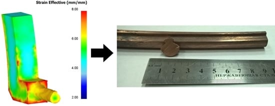
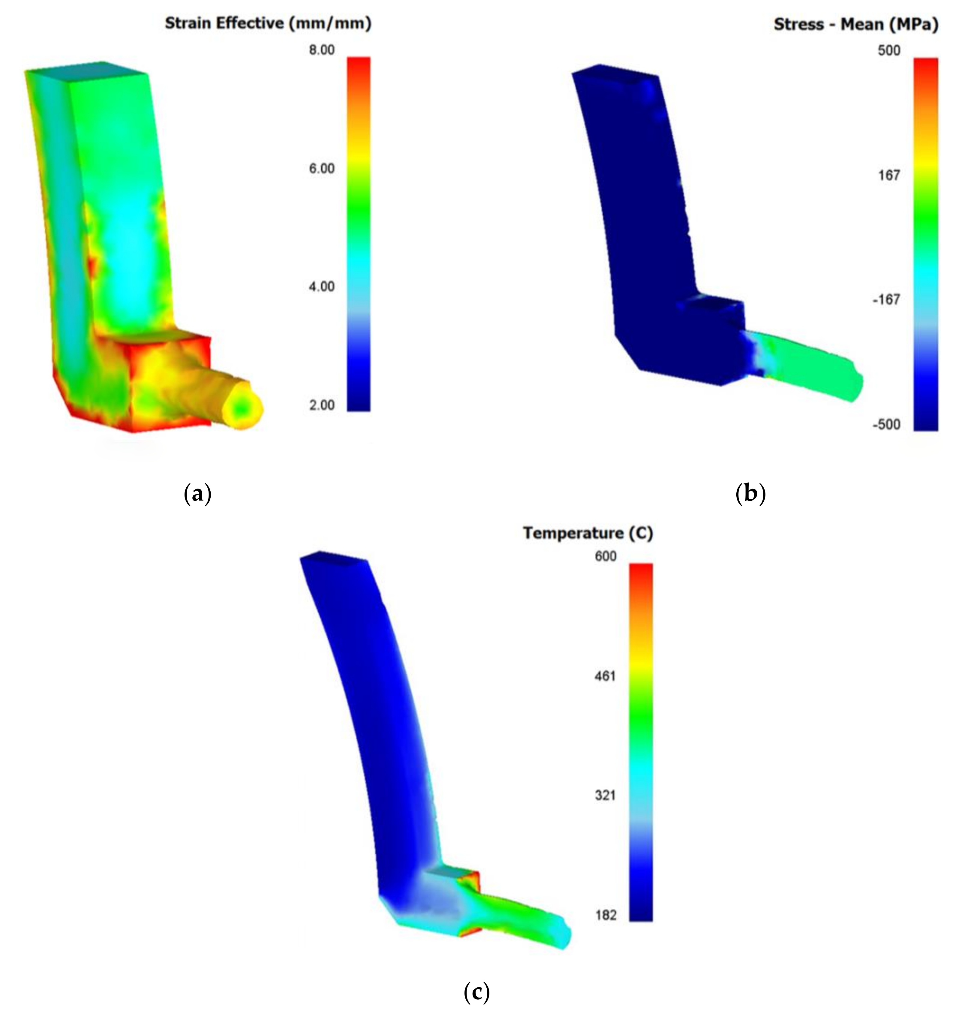
  • A computer simulation was found that during ECAP-C with wire forming a compressive stress of ≥ 500 MPa prevailed in the deformation region, which is known to be beneficial for the material workability.
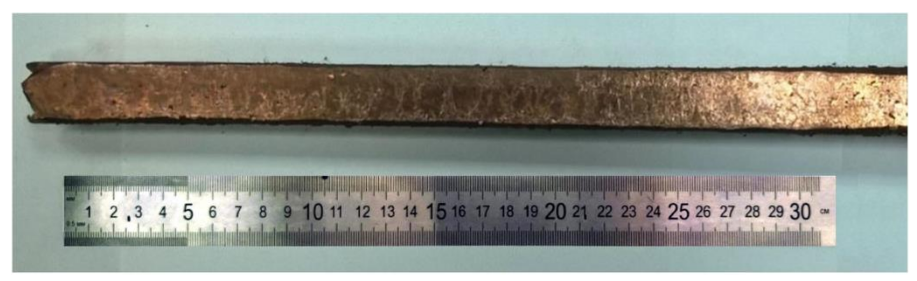
  • Physical experiments enabled the processing of contact wire samples for HS railway lines with complex of physical, mechanical, and service properties that meet modern requirements. The ultimate tensile strength was 560 ± 20 MPa, with an electrical conductivity of 76 ± 2% IACS and a relative tensile elongation of 20 ± 2%.
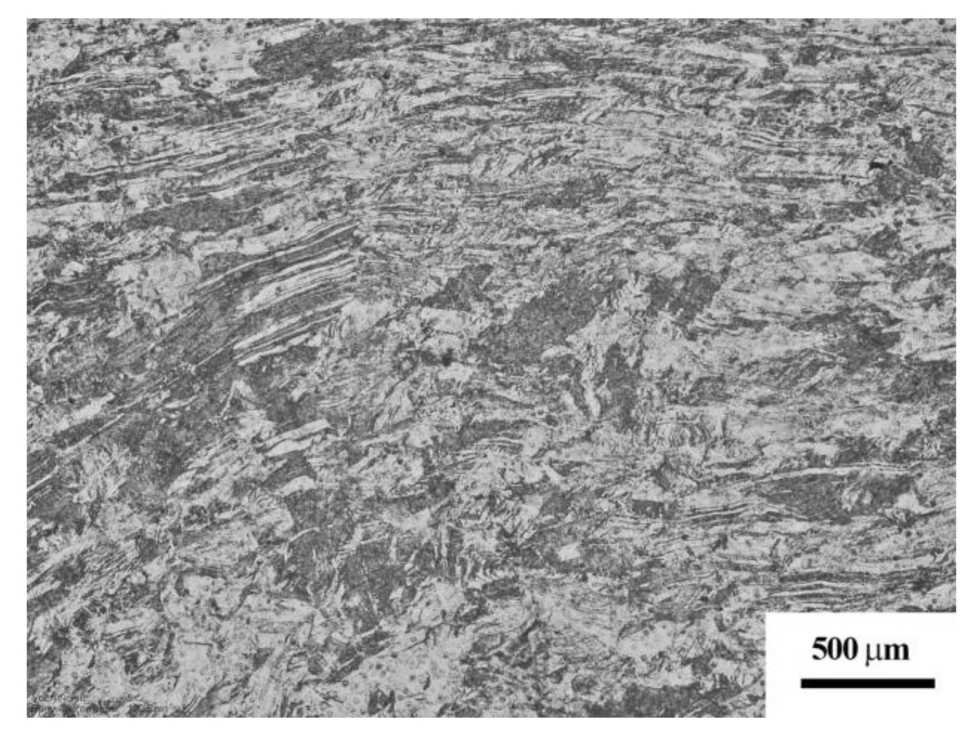
  • The maximum contribution to the refinement therewith was found to be associated with ECAP with wire forming, which resulted in the production of a band structure with a mean size of fragments inside the bands of 300 ± 20 nm (TEM), a CSR of ~110 nm, and a dislocation density of 2.65 × 10¹⁴ m−2. Secondary phase precipitations with an average size of 20 ± 2 nm (TEM) are mainly located at the boundaries of the structure fragments. The distance between particles was 160 ± 15 nm.
  • Further ageing at 450 °C for 1 h led to the growth of the CSR up to 160 ± 10 nm, with a decrease in the dislocation density, down to 1.65 × 10¹⁴ m−2. The average size of fine particles increased to 30 ± 3 nm, and the distance between them decreased to 110 ± 10 nm.

Author Contributions

Conceptualization, G.I.R. and R.N.A.; methodology, R.N.A. and D.A.A.; software, R.N.A.; validation, G.I.R.; investigation, R.N.A. and D.A.A.; data curation, G.I.R.; writing—original draft preparation, R.N.A. and G.I.R.; writing—review and editing, G.I.R., R.N.A., and D.A.A.; visualization, R.N.A., D.A.A.; supervision, G.I.R. All authors have read and agreed to the published version of the manuscript.

Funding

This research was funded by the Russian Science Foundation (project No. 19-19-00432).

Acknowledgments

The authors are grateful to the Center of Collective Use “Nanotech” at USATU (Ufa, Russia) for providing the equipment (TEM and SEM) for structural studies.

Conflicts of Interest

The authors declare no conflict of interest.

References

  1. Song, Y.; Liu, Z.; Duan, F.; Xu, Z.; Lu, X. Wave propagation analysis in high-speed railway catenary system subjected to a moving pantograph. Appl. Math. Mod. 2018, 59, 20–38. [Google Scholar] [CrossRef]
  2. Gershman, I.S.; Mironos, N.V. Requirements to contact wires for high-speed railway transport. Mess. Vniizht 2011, 3, 13–17. (In Russian) [Google Scholar]
  3. Loginov, Y.; Mysik, R. Continuous Casting and Rolling Methods in the Manufacture of Contact wire for Railway Transport. J. SFU Eng. Technol. 2014, 7, 316–326. (In Russian) [Google Scholar]
  4. Asfandiyarov, R.N.; Raab, G.I.; Aksenov, D.A. Modeling of a combined process for the production of contact wires for high-speed railways. IOP Conf. Ser. Mater. Sci. Eng. 2018, 461, 12001. [Google Scholar] [CrossRef]
  5. Nagasawa, H.; Aoki, S.; Kawakita, S. Production of copper alloy trolley wire and hanging stringing. JP Patent 6154838, 3 June 2014. [Google Scholar]
  6. Ymazaki, A. Copper alloy trolley wire. JP Patent 9279269, 28 October 1997. [Google Scholar]
  7. Chandler, T.; Corrado, J. Copper trolley wire and method of manufacturing copper trolley wire. U.S. Patent 6077364, 20 June 2000. [Google Scholar]
  8. Kubo, N.; Nanjo, K.; Sano, T. Trolley wire and manufacturing method. JP Patent 4171907, 29 October 2008. [Google Scholar]
  9. Kuroda, H.; Hiruta, H.; Aoyama, M. Copper alloy material, copper alloy conductor and its production method, trolley wire for overhead contact wire, and cable. JP Patent 5147040, 20 February 2013. [Google Scholar]
  10. Berent, V. Method of producing of contact wires. RUS Patent 2236918, 27 September 2004. (In Russian). [Google Scholar]
  11. Feng, H.; Jiang, H.; Yan, D.; Rong, L. Effect of continuous extrusion on the microstructure and mechanical properties of a CuCrZr alloy. Alloy. Mater. Sci. Eng. A. 2013, 582, 219–224. [Google Scholar] [CrossRef]
  12. Yuan, Y.; Dai, C.; Li, Z.; Yang, G.; Liu, Y.; Xiao, Z. Microstructure evolution of Cu–0.2Mg alloy during continuous extrusion process. J. Mater. Res. 2015, 30, 2783–2791. [Google Scholar] [CrossRef]
  13. Yuan, Y.; Li, Z.; Xiao, Z.; Zhao, Z.; Yang, Z. Microstructure evolution and properties of Cu-Cr alloy during continuous extrusion process. J. Alloys Compd. 2017, 703, 454–460. [Google Scholar] [CrossRef]
  14. Zhu, C.; Ma, A.; Jiang, J.; Li, X.; Song, D.; Yang, D.; Yuan, Y.; Chen, J. Effect of ECAP combined cold working on mechanical properties and electrical conductivity of Conform-produced Cu–Mg alloys. J. Alloys Compd. 2014, 582, 135–140. [Google Scholar] [CrossRef]
  15. Elcowire. Our Product Range. Available online: https://www.elcowire.com/wp-content/uploads/productrange.pdf (accessed on 19 August 2020).
  16. Aluminum Association. Conform Technology: From Ingot to Electric Conductor. Available online: http://www.aluminas.ru/en/media/news/technology_conform_from_the_raw_material_to_conductive_core/ (accessed on 19 August 2020).
  17. Dawson, J.R. Conform Technology for Cost Effective Manufacture of Copper Strip. Available online: https://www.rautomead.com/uploads/files/1515577710BWEconformprocess.pdf (accessed on 19 August 2020).
  18. Faizov, I.; Raab, G.; Aksenov, D. Contributions of various strengthening mechanisms to the flow onset stress in the ECAP-processed Cu-Cr-Zr Alloy. Key Eng. Mater. 2017, 743, 197–202. [Google Scholar] [CrossRef]
  19. Faizov, I.A.; Raab, G.I.; Faizova, S.N.; Zaripov, N.G.; Aksenov, D.A. The role of phase transitions in the evolution of dispersion particles in chromium bronzes upon the equal channel angular pressing. Lett. Mater. 2016, 6, 132–137. (In Russian) [Google Scholar] [CrossRef] [Green Version]
  20. Vinogradov, A.; Ishida, T.; Kitagawa, K.; Kopylov, V.I. Effect of strain path on structure and mechanical behavior of ultrafine grain Cu–Cr alloy produced by equal-channel angular pressing. Acta. Mater. 2005, 53, 2181–2192. [Google Scholar] [CrossRef]
  21. Shan’gina, D.V.; Bochvar, N.R.; Dobatkin, S.V. Structure and properties of Cu-Cr alloys subjected to shear under pressure and subsequent heating. Russ. Metal. 2011, 11, 1046–1052. [Google Scholar] [CrossRef]
  22. Islamgaliev, R.K.; Nesterov, K.M.; Bourgon, J.; Champion, Y.; Valiev, R.Z. Nanostructured Cu-Cr alloy with high strength and electrical conductivity. J. Appl. Phys. 2014, 115, 194301. [Google Scholar] [CrossRef]
  23. Aksenov, D.A.; Asfandiyarov, R.; Raab, G.I.; Isyandavletova, G.B. Features of the physico-mechanical behavior of UFG low-alloyed bronze Cu-1Cr-0.08Zr produced by severe plastic deformation. IOP Conf. Ser. Mater. Sci. Eng. 2017, 4, 12001. [Google Scholar] [CrossRef] [Green Version]
  24. Loginov, Y. Copper and Deformable Copper Alloys; UGTU: Ekaterinburg, Russia, 2006; p. 136. (In Russian) [Google Scholar]
  25. Leoni, M.; Confente, T.; Scardi, P. PM2K: A flexible program implementing Whole Powder Pattern Modelling. Z. Krist. Suppl. 2006, 23, 249–254. [Google Scholar] [CrossRef]
  26. Morozova, A.; Mishnev, R.; Belyakov, A.; Kaibyshev, R. Microstructure and properties of fine grained Cu-Cr-Zr alloys after termo-mechanical treatments. Adv. Mater. Sci. 2018, 54, 56–92. [Google Scholar] [CrossRef]
  27. Utyashev, F.Z.; Raab, G.I. Mechanisms and model of structure formation in metals during severe deformation. Phys. Technol. High Press. 2006, 16, 73–78. [Google Scholar]
  28. Chen, X.; Jiang, F.; Jiang, J.; Xu, P.; Tong, M.; Tang, Z. Precipitation, Recrystallization, and Evolution of Annealing Twins in a Cu-Cr-Zr Alloy. Metals 2018, 8, 227. [Google Scholar] [CrossRef] [Green Version]
Figure 1. Laboratory samples after radial swaging with a degree of accumulated strain of e = 1.5.
Metals 10 01476 g001
Figure 2. Initial sample structure processed via the radial swaging (light microscopy).
Metals 10 01476 g002
Figure 3. Computer simulation of Conform scheme (ECAP-C) with wire forming: (a) distribution fields of accumulated strain in the billet (cross-section), (b) mean stress fields in the deformation region (longitudinal section), and (c) temperature distribution fields (longitudinal section).
Metals 10 01476 g003
Figure 4. Laboratory samples after ECAP with wire forming (a) and area for microstructural analysis (b).
Metals 10 01476 g004
Figure 5. Structure of the sample after ECAP with wire forming: (a) the longitudinal section (TEM, light-field image, and arrows show secondary phase precipitates) and (b) the cross-section (TEM, dark-field image, and arrows show secondary phase precipitates).
Metals 10 01476 g005
Figure 6. Structure of the sample after ECAP with wire forming and aging (longitudinal section): (a) TEM—light-field image (arrows show secondary phase precipitates) and (b) TEM—dark-field image (arrows show secondary phase precipitates).
Metals 10 01476 g006
Figure 7. EBSD analysis: (a) orientational map after ECAP with wire forming and aging and (b) the bar chart of angle misorientation distribution.
Metals 10 01476 g007
Figure 8. Stress curves: (a) initial state, (b) ECAP with wire forming, and (c) ECAP with wire forming + aging.
Metals 10 01476 g008
Table 1. X-ray structure analysis.
StateCSR, nmMicrodeformation, ehkl, %Dislocation Density ρ, 1014 m−2Lattice Parameter, Ǻ
Initial (radial swaging)220 ± 120.127 ± 0.0211.71 ± 0.023.6170 ± 0.0004
ECAP with a wire forming110 ± 100.158 ± 0.0252.65 ± 0.043.6160 ± 0.0007
ECAP with a wire forming + aging at 450 °C, 1 h160 ± 100.120 ± 0.0201.65 ± 0.023.6150 ± 0.0006
Publisher’s Note: MDPI stays neutral with regard to jurisdictional claims in published maps and institutional affiliations.

