Development of the Structure of Cemented Carbides during Their Processing by SLM and HIP

 ,
,  ,
,
Abstract
:
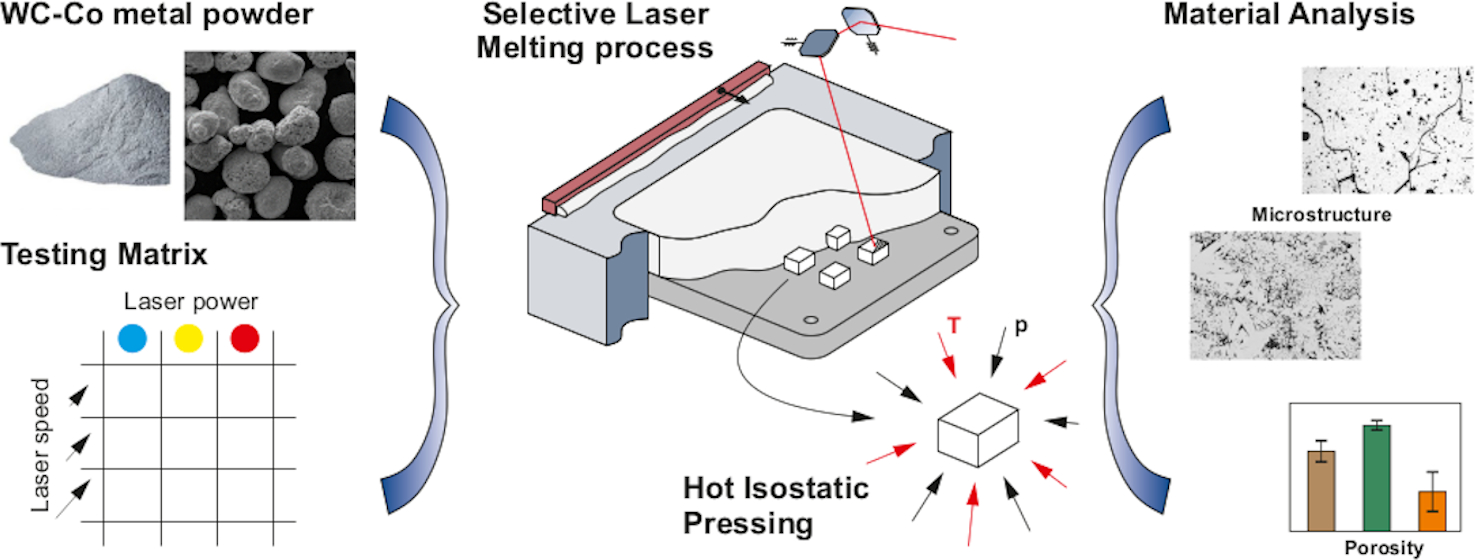
1. Introduction
2. Materials and Methods
2.1. Experimental Material
Powder Mixtures
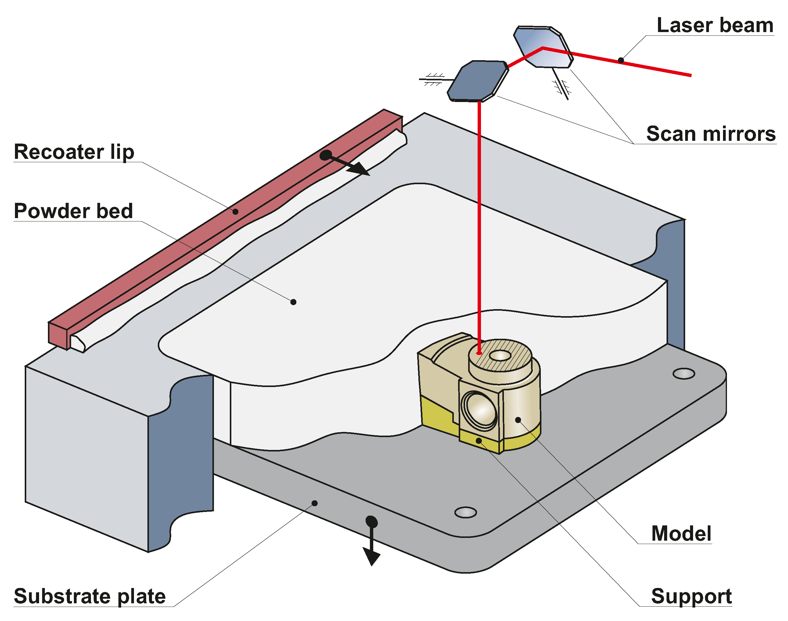
2.2. Selective Laser Melting Technology
2.3. The Methodology of Testing Powder Mixture AW701
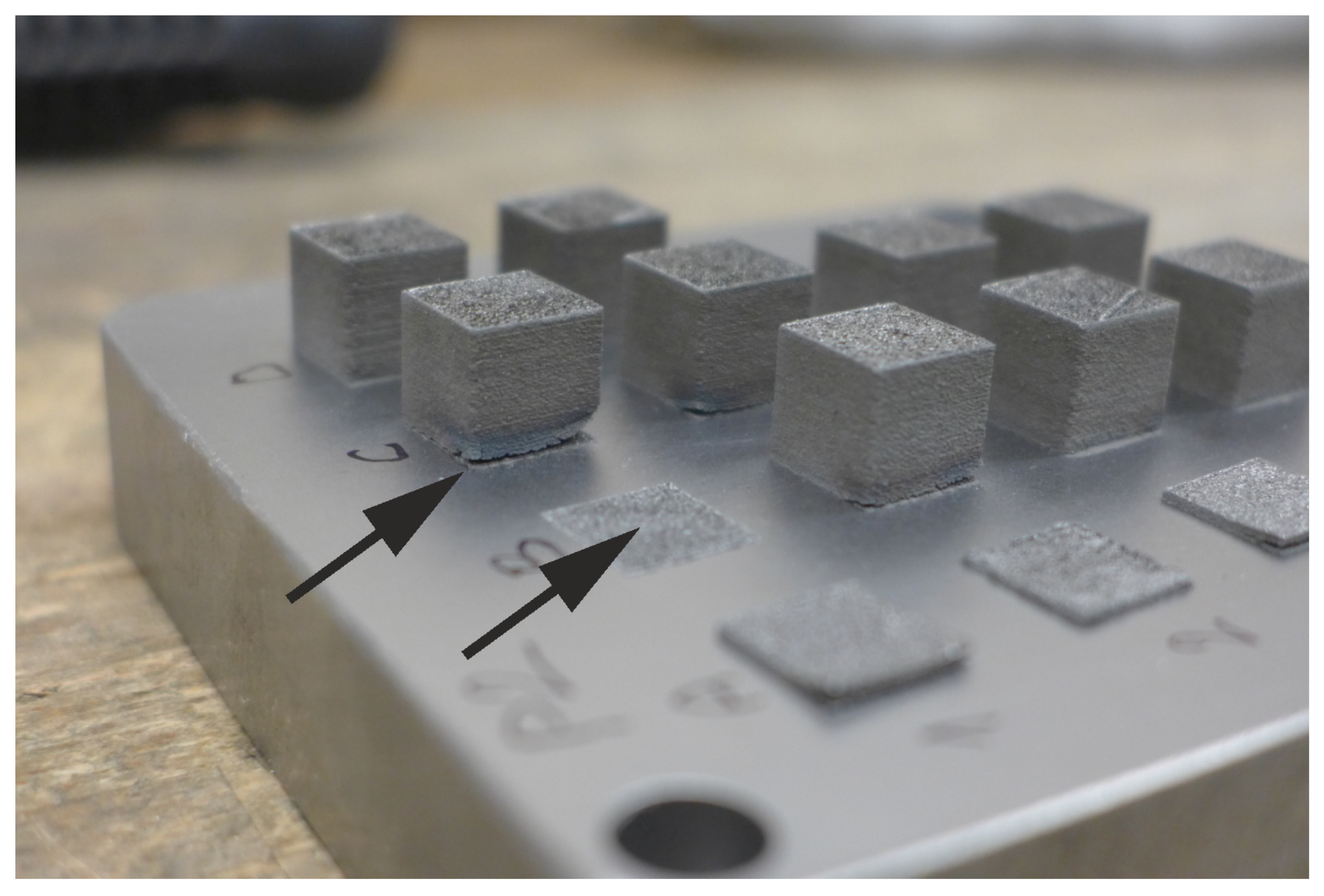
Samples after SLM Process and HIP Process
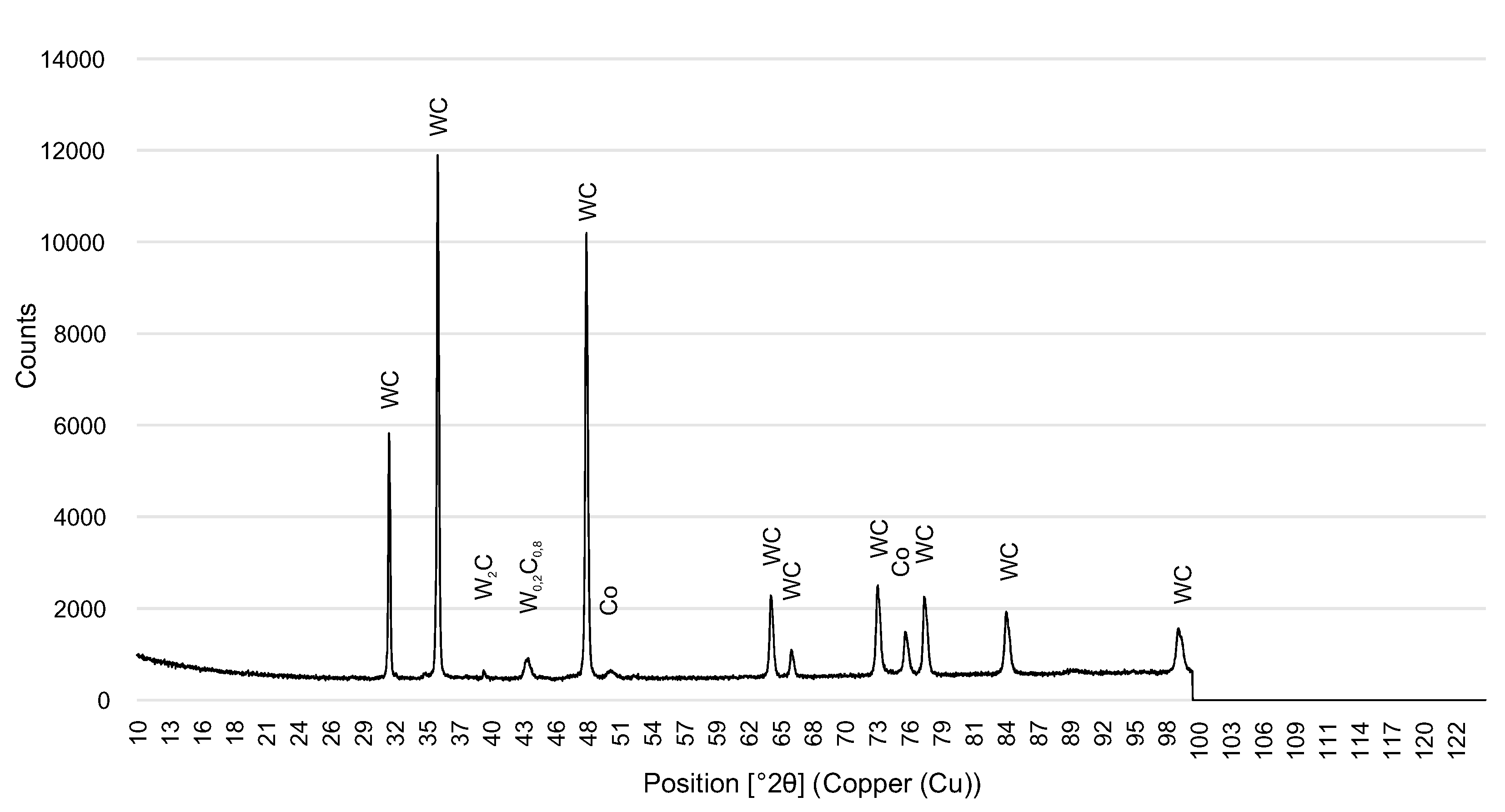
3. Results
Samples after SLM Process and HIP Process
4. Conclusions
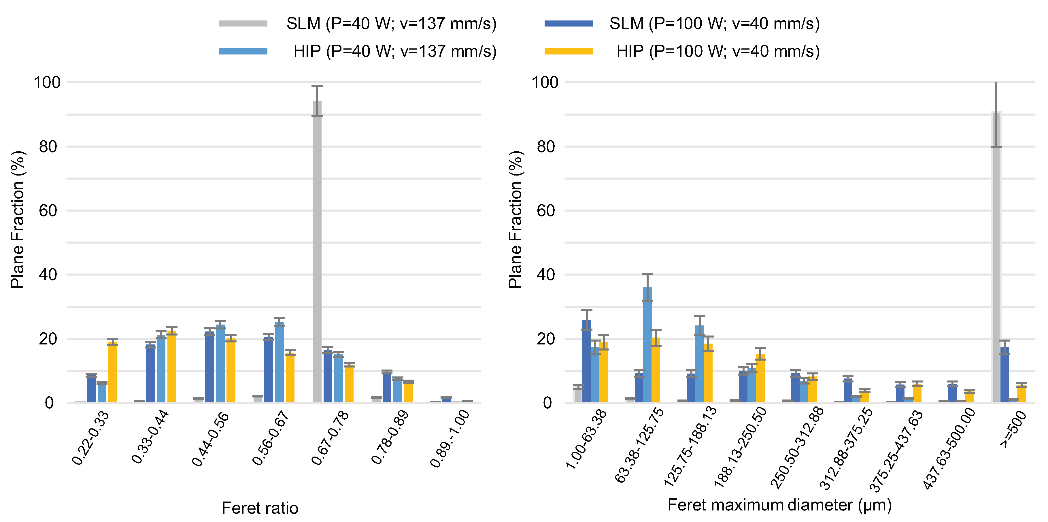
- The size distribution and shape of WC-Co particles are equal to those of the reference steel powder. However, the fraction of microscopic particles which cause higher friction is lower. Consequently, the WC-Co powder mixture shows better flowability and wider spread on the build plate than the reference powder.
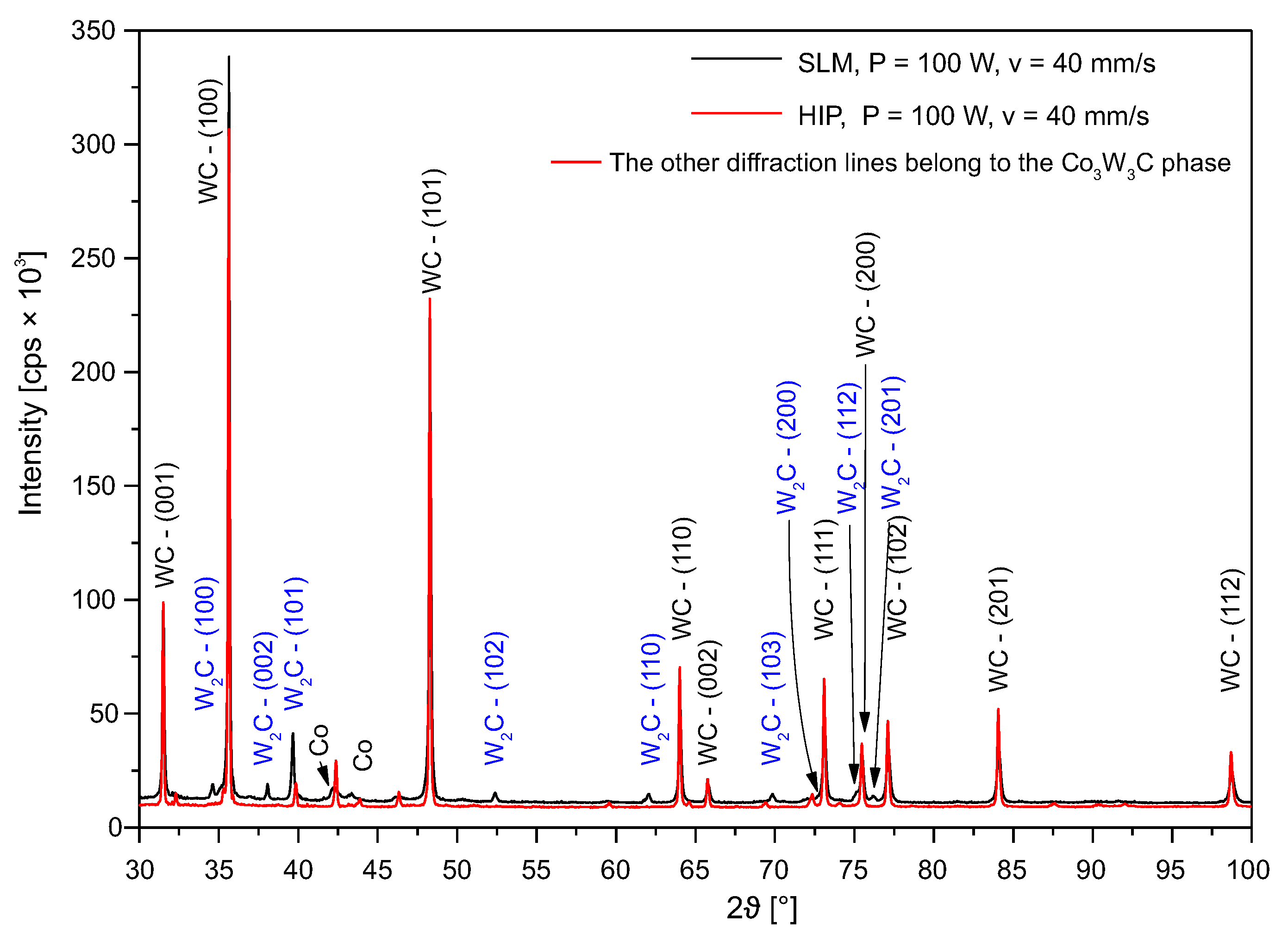
- By varying the amount of VED, one can control the phase structure and type of pores in SLM builds from WC-Co. By this means, interconnected irregular-shaped pores produced with VED under 100 J/mm can be changed into closed pores and cracks at higher VED above approx. 200 J/mm. The formation of cracks was associated with the loss of Co binder—the -phase was due to evaporation, the coarsening of -phase WC, the precipitation of -phase, and stresses induced by temperature gradients. The process led to precipitation of -phase and WC. The type of -phase depended on the VED value. All the microstructural changes played a role in obtaining the post-SLM relative density which was 65–88%, depending on VED.
Author Contributions
Funding
Conflicts of Interest
Abbreviations
| SLM | Selective Laser Melting |
| HIP | Hot Isostatic Pressing |
| VED | Volumetric Energy Density |
| CC | Cemented Carbides |
| AM | Additive Manufacturing |
| EDS | Energy Dispersive X-Ray Spectroscopy |
References
- Sarin, V. Comprehensive Hard Materials; Elsevier: Newnes, Australia, 2014; Volume 1, Chapters 3–4. [Google Scholar]
- Upadhyaya, G.S. Cemented Tungsten Carbides: Production, Properties and Testing; William Andrew: Noyes, OH, USA, 1998; Chapters 3–7. [Google Scholar]
- Kurlov, A.S.; Gusev, A.I. Tungsten Carbides; Springer International Publishing: Berlin/Heidelberg, Germany, 2013; pp. 191–237. [Google Scholar] [CrossRef]
- Kříž, A.; Bricín, D. Properties and Testing of Cemented Carbides; Intech: Rijeka, Croatia, 2017; pp. 273–297. [Google Scholar] [CrossRef] [Green Version]
- García, J.; Ciprés, V.C.; Blomqvist, A.; Kaplan, B. Cemented Carbide Microstructures: A Review; Elsevier: Amsterdam, The Netherlands, 2019; Volume 80, pp. 40–68. [Google Scholar] [CrossRef]
- Klaasen, H.; Kübarsepp, J. Wear of Advanced Cemented Carbides for Metalforming Tool Materials; Elsevier: Amsterdam, The Netherlands, 2004; Volume 256, pp. 846–853. [Google Scholar] [CrossRef]
- Prakash, L.J. Application of Fine Grained Tungsten Carbide Based Cemented Carbides; Elsevier: Amsterdam, The Netherlands, 1995; Volume 13, pp. 257–264. [Google Scholar] [CrossRef]
- Yang, J.; Odén, M.; Johansson-Jõesaar, M.; Llanes, L. Grinding Effects on Surface Integrity and Mechanical Strength of WC-Co Cemented Carbides; Elsevier: Amsterdam, The Netherlands, 2014; Volume 13, pp. 257–263. [Google Scholar] [CrossRef] [Green Version]
- Bricín, D.; Průcha, V.; Kříž, A. Texturing of WC-Co Substrate Surface to Improve the Resistance of Deposited PVD Film to Wear and Dynamic Loads; Elsevier: Amsterdam, The Netherlands, 2017; Volume 13, pp. 702–709. [Google Scholar] [CrossRef]
- Arroyo, J.M.; Diniz, A.E.; de Lima, M.S.F. Cemented Carbide Surface Modifications Using Laser Treatment and Its Effects on Hard Coating Adhesion; Elsevier: Amsterdam, The Netherlands, 2010; Volume 204, pp. 2410–2416. [Google Scholar] [CrossRef]
- Gibson, I.; Rosen, D.; Stucker, B. Additive Manufacturing Technologies; Springer: Berlin/Heidelberg, Germany, 2015. [Google Scholar] [CrossRef]
- Bandyopadhyay, A.; Bose, S. Additive Manufacturing; CRC Press: Boca Raton, FL, USA, 2016. [Google Scholar]
- Kumar, S. Process Chain Development for Additive Manufacturing of Cemented Carbide; Elsevier: Amsterdam, The Netherlands, 2018; Volume 34, pp. 121–130. [Google Scholar] [CrossRef]
- Johnson, J.L.; Enneti, R.K. Preface to Special Issue on 3D Printing of Refractory Metals and Hard Materials; Elsevier: Amsterdam, The Netherlands, 2020; Volume 88. [Google Scholar] [CrossRef]
- Venuvinod, P.K.; Ma, W. Rapid Prototyping; Springer: Berlin/Heidelberg, Germany, 2004; Chapters 2, 7; pp. 25–55, 245–277. [Google Scholar] [CrossRef]
- Pacurar, R.; Pacurar, A. Applications of the Selective Laser Melting Technology in the Industrial and Medical Fields; IntechOpen Limited: Rijeka, Croatia, 2016; pp. 161–185. [Google Scholar] [CrossRef] [Green Version]
- Association, E.P.M. Introduction to Additive Manufacturing Technology, 2nd ed.; European Powder Metallurgy Association: Shrewsbury, UK, 2017. [Google Scholar]
- Sames, W.J.; List, F.A.; Pannala, S.; Dehoff, R.R.; Babu, S.S. The Metallurgy and Processing Science of Metal Additive Manufacturing; Taylor & Francis: Oxford, UK, 2016; Volume 61, pp. 315–360. [Google Scholar] [CrossRef]
- Zetková, I. Complexity of Metal Mechanical Components Production by 3D Printing; University of West Bohemia: Pilsen, Czechia, 2017; pp. 19–25. [Google Scholar]
- Neikov, O.D. Handbook of Non-Ferrous Metal Powders; Elsevier: Amsterdam, The Netherlands, 2009; pp. 65–399. [Google Scholar]
- Uhlmann, E.; Bergmann, A.; Gridin, W. Investigation on Additive Manufacturing of Tungsten Carbide-Cobalt by Selective Laser Melting; Elsevier: Amsterdam, The Netherlands, 2015; Volume 35, pp. 8–15. [Google Scholar] [CrossRef]
- Kruth, J.P.; Levy, G.; Klocke, F.; Childs, T. Consolidation Phenomena in Laser and Powder-Bed Based Layered Manufacturing; Elsevier: Amsterdam, The Netherlands, 2007; Volume 56, pp. 730–759. [Google Scholar] [CrossRef]
- Gu, D. Laser Additive Manufacturing of High-Performance Materials; Springer: Berlin/Heidelberg, Germany, 2015; ISBN 978-3-662-46088-7. [Google Scholar] [CrossRef]
- Prashanth, K.; Scudino, S.; Maity, T.; Das, J.; Eckert, J. Is the energy density a reliable parameter for materials synthesis by selective laser melting? Mater. Res. Lett. 2017, 5, 386–390. [Google Scholar] [CrossRef] [Green Version]
- Wang, X.C.; Laoui, T.; Bonse, J.; Kruth, J.P.; Lauwers, B.; Froyen, L. Direct Selective Laser Sintering of Hard Metal Powders: Experimental Study and Simulation; Springer: Berlin/Heidelberg, Germany, 2002; Volume 19, pp. 351–357. [Google Scholar] [CrossRef]
- Gu, D.; Meiners, W. Microstructure Characteristics and Formation Mechanisms of In Situ WC Cemented Carbide Based Hardmetals Prepared by Selective Laser Melting; Elsevier: Amsterdam, The Netherlands, 2010; Volume 527, pp. 7585–7592. [Google Scholar] [CrossRef]
- Iveković, A.; Omidvari, N.; Vrancken, B.; Lietaert, K.; Thijs, L.; Vanmeensel, K.; Vleugels, J.; Kruth, J.P. Selective laser Melting of Tungsten and Tungsten Alloys; Elsevier: Amsterdam, The Netherlands, 2018; Volume 72, pp. 27–32. [Google Scholar] [CrossRef]
- Zhou, X.; Liu, X.; Zhang, D.; Shen, Z.; Liu, W. Balling Phenomena in Selective Laser Melted Tungsten; Elsevier: Amsterdam, The Netherlands, 2015; Volume 222, pp. 33–42. [Google Scholar] [CrossRef]
- Khmyrov, R.; Safronov, V.; Gusarov, A. Obtaining Crack-Free WC-Co Alloys by Selective Laser Melting; Elsevier: Amsterdam, The Netherlands, 2016; Volume 83, pp. 874–881. [Google Scholar] [CrossRef] [Green Version]
- Maeda, K.; Childs, T. Laser Sintering (SLS) of Hard Metal Powders for Abrasion Resistant Coatings; Elsevier: Amsterdam, The Netherlands, 2004; Volume 149, pp. 609–615. [Google Scholar] [CrossRef]
- Kumar, S. Manufacturing of WC–Co Moulds Using SLS Machine; Elsevier: Amsterdam, The Netherlands, 2009; Volume 209, pp. 3840–3848. [Google Scholar] [CrossRef]
- Domashenkov, A.; Borbély, A.; Smurov, I. Structural Modifications of WC/Co Nanophased and Conventional Powders Processed by Selective Laser Melting; Taylor & Francis: Oxford, UK, 2016; Volume 32, pp. 93–100. [Google Scholar] [CrossRef]
- Torralba, J. Improvement of Mechanical and Physical Properties in Powder Metallurgy; Elsevier: Amsterdam, The Netherlands, 2014; Volume 3, pp. 281–294. [Google Scholar] [CrossRef]
- Heaney, D.; Binet, C. Hot Isostatic Pressing (HIP) of Metal Injection Molding (MIM); Woodhead Publishing: Sawston, UK, 2019; pp. 195–202. [Google Scholar] [CrossRef]
- Bhatti, A.; Farries, P. Preparation of Long-Fiber-Reinforced Dense Glass and Ceramic Matrix Composites; Elsevier: Amsterdam, The Netherlands, 2000; Volume 4, pp. 645–667. [Google Scholar] [CrossRef]
- Bricín, D.; Kříž, A. Assessment of Usability of WC-Co Powder Mixtures for SLM. Manuf. Technol. 2020, 18, 719–726. [Google Scholar] [CrossRef]
- Bricín, D.; Kříž, A. Comparison of the effect of the applied energy on the properties of prtotypes made from different types of powder mixtures. MM Sci. J. 2020, 2020, 3800–3805. [Google Scholar] [CrossRef]
- International Organization for Standardization. ISO 4490:2014 Metallic Powders—Determination of Flow Rate by Means of a Calibrated Funnel (Hall Flowmeter); International Organization for Standardization: Geneva, Switzerland, 2014. [Google Scholar]
- Kozior, T.; Bochnia, J. The influence of printing orientation on surface texture parameters in powder bed fusion technology with 316L steek. Micromachines 2020, 11, 639. [Google Scholar] [CrossRef] [PubMed]
- Kozior, T.; Bochnia, J.; Zmarzły, P.; Gogolewski, D.; Mathia, T.G. Waviness of freeform surface characterizations from austenitic stainless steel (316L) manufactured by 3D printing-selective laser melting (SLM) technology. Materials 2020, 13, 4372. [Google Scholar] [CrossRef] [PubMed]
- Khorasani, A.; Gibson, I.; Awan, U.S.; Ghaderi, A. The effect of SLM process parameters on density, hardness, tensile strength and surface quality of Ti-6Al-4V. Addit. Manuf. 2019, 25, 176–186. [Google Scholar] [CrossRef]
- ASTM. ASTM B657-18 Standard Guide for Metallographic Identification of Microstructure in Cemented Carbides; ASTM International: West Conshohocken, PA, USA, 2000. [Google Scholar]
- Bricín, D.; Špirit, Z.; Kříž, A. Metallographic Analysis of the Suitability of a WC-Co Powder Blend for Selective Laser Melting Technology; Trans Tech Publications Ltd.: Pfaffikon, Switzerland, 2018; Volume 919, pp. 3–9. [Google Scholar] [CrossRef]
- Khairallah, S.A.; Anderson, A.T.; Rubenchik, A.; King, W.E. Laser Powder-Bed Fusion Additive Manufacturing: Physics of Complex Melt Flow and Formation Mechanisms of Pores, Spatter, and Denudation Zones; Elsevier: Amsterdam, The Netherlands, 2016; Volume 108, pp. 36–45. [Google Scholar] [CrossRef] [Green Version]
- Zhong, Y.; Zhu, H.; Shaw, L.L.; Ramprasad, R. The Equilibrium Morphology of WC Particles—A Combined ab Initio and Experimental Study; Elsevier: Amsterdam, The Netherlands, 2011; Volume 59, pp. 3748–3757. [Google Scholar] [CrossRef]
- Huo, S.; Qian, M.; Schaffer, G.; Crossin, E. Aluminium Powder Metallurgy; Woodhead Publishing: Sawston, UK, 2011; pp. 655–701. [Google Scholar] [CrossRef]


| Powder Type | AW701 | PH1 |
|---|---|---|
| Flowability [s/0.2 kg] | 2.7 ± 0.2 | 3.7 ± 0.1 |
| Bulk density [kg/m] | 5970 ± 900 | 4200 ± 600 |
| Tap density [kg/m] | 7290 ± 110 | 4600 ± 700 |
| Mean spread powder width [mm] | 4.6 ± 0.5 | 3.5 ± 0.5 |
| Laser Power | Scan Speed | Volumetric Energy Density | Note |
|---|---|---|---|
| P [W] | v [mm/s] | E [J/mm] | |
| 40 | 152 | 54 | |
| 40 | 140 | 60 | |
| 40 | 128 | 65 | |
| 40 | 111 | 75 | |
| 40 | 100 | 83 | |
| 40 | 83 | 100 | |
| 40 | 55.5 | 150 | |
| 40 | 35 | 238 | |
| 80 | 175 | 95 | Stopped |
| 80 | 166 | 100 | Stopped |
| 80 | 145 | 114 | Stopped |
| 80 | 128 | 130 | Stopped |
| 80 | 111 | 150 | Stopped |
| 80 | 100 | 166 | |
| 80 | 95 | 175 | |
| 80 | 90 | 185 | |
| 80 | 85 | 196 | |
| 80 | 80 | 208 | |
| 80 | 75 | 222 | |
| 80 | 70 | 238 | |
| 80 | 49 | 340 | |
| 80 | 32 | 520 | |
| 100 | 209 | 99 | |
| 100 | 181 | 115 | |
| 100 | 139 | 149 | Stopped |
| 100 | 87.5 | 238 | |
| 100 | 61.2 | 340 | |
| 100 | 40 | 520 |
| SLM | HIP | SLM | HIP | |
|---|---|---|---|---|
| Phase | P = 100 W v = 40 mm/s | P = 100 W v = 40 mm/s | P = 40 W v = 137 mm/s | P = 40 W v = 137 mm/s |
| WC | 87.5 | 92.4 | 25.3 | 97 |
| WC | 8.5 | – | 70 | – |
| Co | 0.8 | 0.3 | 4.3 | 2.4 |
| CoWC | 0.3 | 7.3 | – | – |
| COWC | – | – | 0.4 | 0.6 |
| COWC | 2.9 | – | – | – |
Publisher’s Note: MDPI stays neutral with regard to jurisdictional claims in published maps and institutional affiliations. |
© 2020 by the authors. Licensee MDPI, Basel, Switzerland. This article is an open access article distributed under the terms and conditions of the Creative Commons Attribution (CC BY) license (http://creativecommons.org/licenses/by/4.0/).
Share and Cite
Bricín, D.; Ackermann, M.; Jansa, Z.; Kubátová, D.; Kříž, A.; Špirit, Z.; Šafka, J. Development of the Structure of Cemented Carbides during Their Processing by SLM and HIP. Metals 2020, 10, 1477. https://doi.org/10.3390/met10111477
Bricín D, Ackermann M, Jansa Z, Kubátová D, Kříž A, Špirit Z, Šafka J. Development of the Structure of Cemented Carbides during Their Processing by SLM and HIP. Metals. 2020; 10(11):1477. https://doi.org/10.3390/met10111477
Chicago/Turabian StyleBricín, David, Michal Ackermann, Zdeněk Jansa, Dana Kubátová, Antonín Kříž, Zbyněk Špirit, and Jiří Šafka. 2020. "Development of the Structure of Cemented Carbides during Their Processing by SLM and HIP" Metals 10, no. 11: 1477. https://doi.org/10.3390/met10111477