Effect of Die Angle and Frictional Conditions on Fine Grain Layer Generation in Multipass Drawing of High Carbon Steel Wire


Abstract
:1. Introduction
2. Material, Process and Methods
3. Results
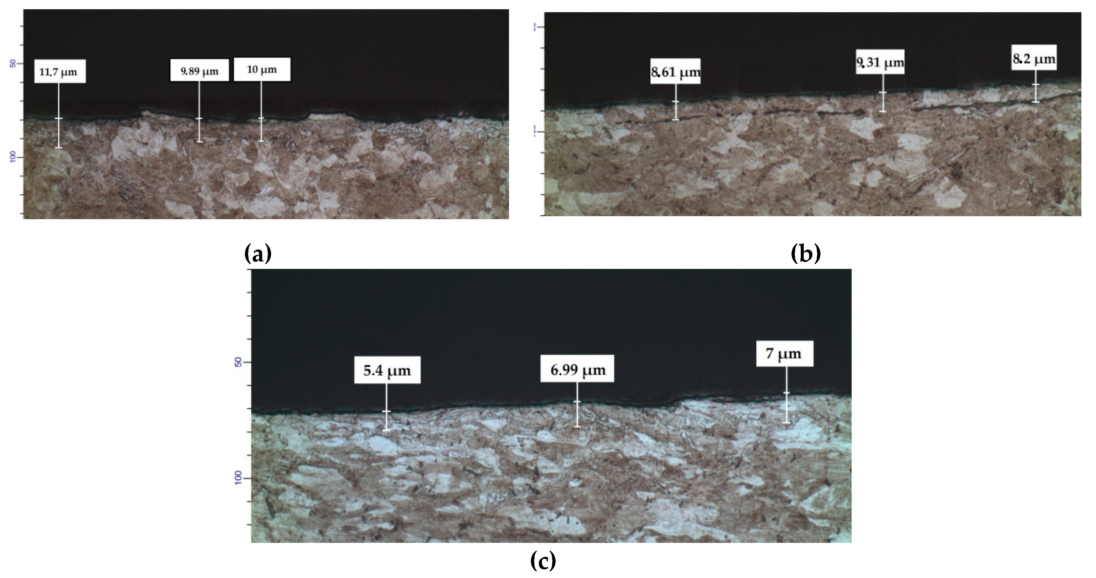
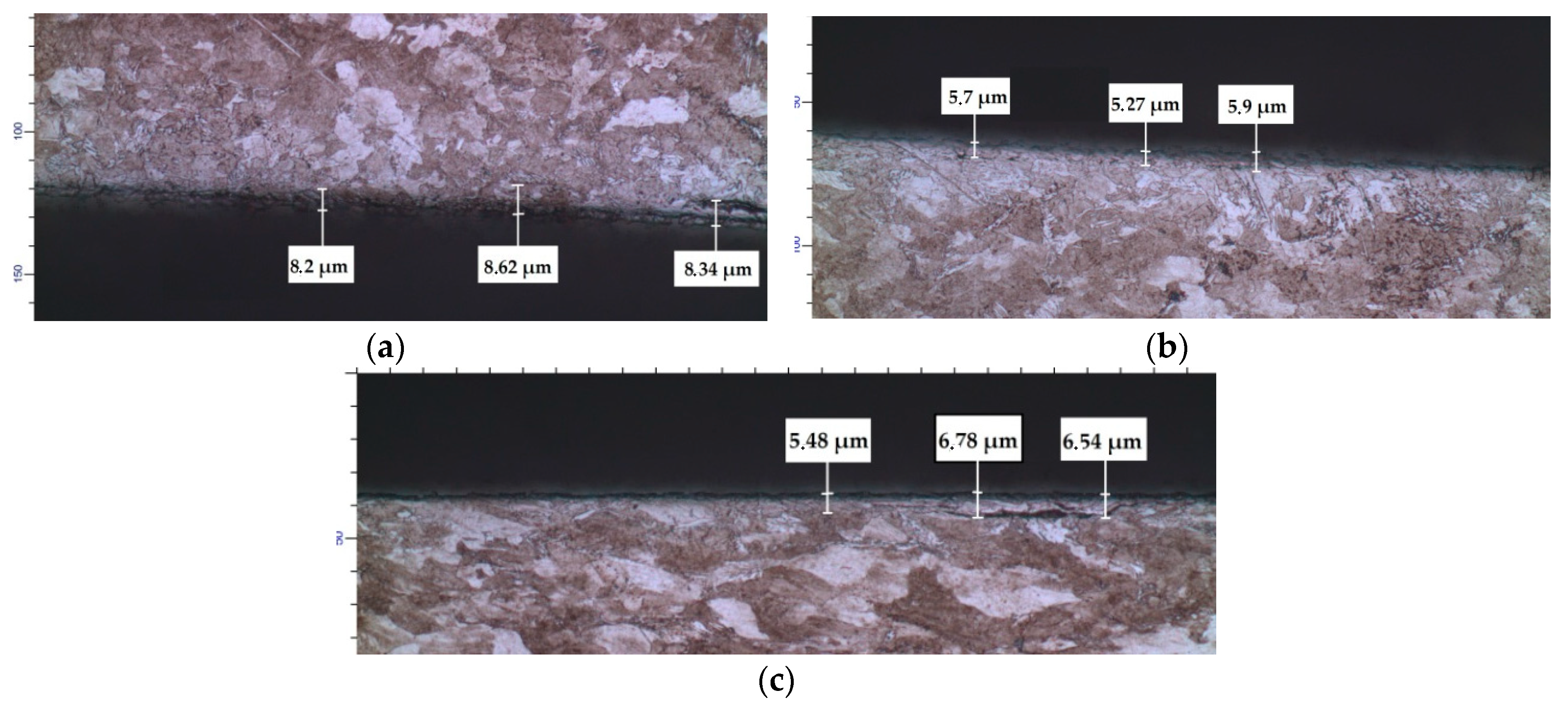
3.1. Soft Friction Conditions
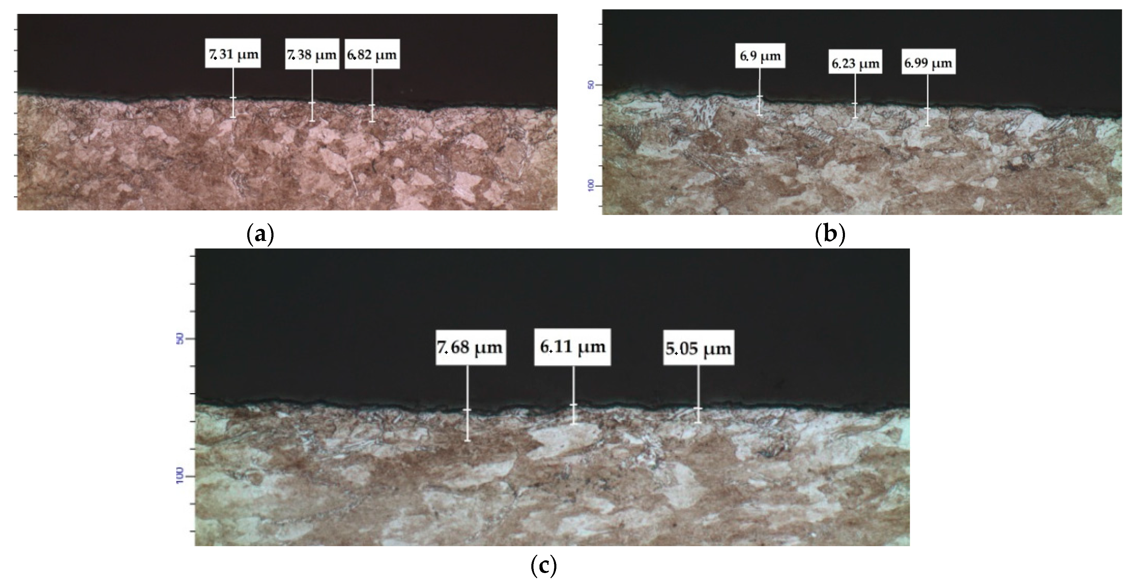
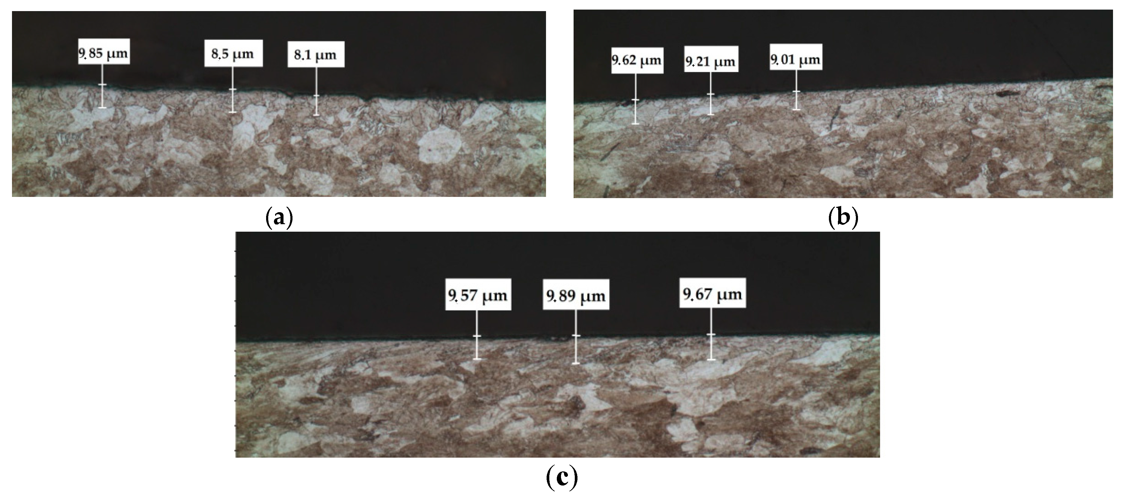
3.2. Hard Friction Conditions
4. Discussion
5. Conclusions
- (1)
- The thickness of fine grain layers generated in the multipass drawing process is qualitatively affected by friction conditions.
- (2)
- Under soft friction conditions, the fine grain layer thickness decreases during the consequential passes for both die semiangles, 4° and 5°.
- (3)
- Under hard friction conditions, the thickness may or may not be a monotonic function of the number of passes, and its general qualitative behavior depends on the die semiangle.
Author Contributions
Funding
Conflicts of Interest
References
- Griffiths, B.J. Mechanisms of White Layer Generation with Reference to Machining and Deformation Processes. ASME J. Tribol. 1987, 109, 525–530. [Google Scholar] [CrossRef]
- Sanabria, V.; Mueller, S.; Reimers, W. Microstructure Evolution of Friction Boundary Layer during Extrusion of AA 6060. Procedia Eng. 2014, 81, 586–591. [Google Scholar] [CrossRef] [Green Version]
- Griffiths, B.J.; Furze, D.C. Tribological Advantages of White Layers Produced by Machining. ASME J. Tribol. 1987, 109, 338–342. [Google Scholar] [CrossRef]
- Kim, Y.-T.; Ikeda, K. Flow Behavior of the Billet Surface Layer in Porthole Die Extrusion of Aluminum. Metal. Mater. Trans. 2000, 31A, 1635–1643. [Google Scholar] [CrossRef]
- Warren, A.W.; Guo, Y.B. Numerical Investigation on the Effects of Machining-Induced White Layer during Rolling Contact. Tribol. Trans. 2005, 48, 436–441. [Google Scholar] [CrossRef]
- Kajino, S.; Asakawa, M. Effect of “Additional Shear Strain Layer” on Tensile Strength and Microstructure of Fine Drawn Wire. Mater. Process. Technol. 2006, 177, 704–708. [Google Scholar] [CrossRef]
- Choi, Y. Influence of a White Layer on the Performance of Hard Machined Surfaces in Rolling Contact. Proc. Inst. Mech. Eng. Part B J. Eng. Manufact. 2010, 224, 1207–1215. [Google Scholar] [CrossRef]
- Hwang, Y.-M.; Huang, T.-H.; Alexandrov, S. Manufacture of Gradient Microstructures of Magnesium Alloys Using Two—Stage Extrusion Dies. Steel Res. Int. 2015, 86, 956–961. [Google Scholar] [CrossRef]
- Alexandrov, S.; Jeng, Y.-R.; Hwang, Y.-M. Generation of a Fine Grain Layer in the Vicinity of Frictional Interfaces in Direct Extrusion of AZ31 Alloy. ASME J. Manuf. Sci. Eng. 2015, 137, 051003. [Google Scholar] [CrossRef]
- Stolyarov, A.; Polyakova, M.; Atangulova, G.; Alexandrov, S.; Lang, L. Effect of Frictional Conditions on the Generation of Fine Grain Layers in Drawing of Thin Steel Wires. Metals 2019, 9, 819. [Google Scholar] [CrossRef] [Green Version]
- Kharitonov, V.A.; Stolyarov, A.Y.; Lataev, A.P. Determining the Depth of the Layer of Additional Shear Deformation in Drawing of Thin Wire. Steel 2012, 12, 45–47. [Google Scholar]
- Rubio, E.M.; Camacho, A.M.; Perez, R.; Marin, M.M. Guidelines for Selecting Plugs Used in Thin-Walled Tube Drawing Processes of Metallic Alloys. Metals 2017, 7, 572. [Google Scholar] [CrossRef] [Green Version]
- Medvedev, A.; Arutyunyan, A.; Lomakin, I.; Bondarenko, A.; Kazykhanov, V.; Enikeev, N.; Raab, G.; Murashkin, M. Fatigue Properties of Ultra-Fine Grained Al-Mg-Si Wires with Enhanced Mechanical Strength and Electrical Conductivity. Metals 2018, 8, 1034. [Google Scholar] [CrossRef] [Green Version]
- Martinez, G.A.S.; Santos, E.F.; Kabayama, L.K.; Guidi, E.S.; Silva, F.A. Influences of Different Die Bearing Geometries on the Wire-Drawing Process. Metals 2019, 9, 1089. [Google Scholar] [CrossRef] [Green Version]
- Belov, N.; Murashkin, M.; Korotkova, N.; Akopyan, T.; Timofeev, V. Structure and Properties of Al–0.6wt.%Zr Wire Alloy Manufactured by Direct Drawing of Electromagnetically Cast Wire Rod. Metals 2020, 10, 769. [Google Scholar] [CrossRef]
- Santana Martinez, G.A.; Qian, W.-L.; Kabayama, L.K.; Prisco, U. Effect of Process Parameters in Copper-Wire Drawing. Metals 2020, 10, 105. [Google Scholar] [CrossRef] [Green Version]
- Prisco, U.; Martinez, G.A.; Kabayama, L.K. Effect of Die Pressure on the Lubricating Regimes Achieved in Wire Drawing. Prod. Eng. 2020. [Google Scholar] [CrossRef]
- Thomsen, E.G. Stress-Strain Properties of Tough-Pitch Copper After Multi-Pass Drawing and Extruding. ASME J. Eng. Mater. Technol. 1983, 105, 178–181. [Google Scholar] [CrossRef]
- Kuboki, T.; Abe, M.; Neishi, Y.; Akiyama, M. Design Method of Die Geometry and Pass Schedule by Void Index in Multi-Pas Drawing. ASME J. Manuf. Sci. Eng. 2005, 127, 173–181. [Google Scholar] [CrossRef]
- Lee, S.-K.; Lee, I.-K.; Lee, S.-Y. Development of a Multi-Pass Drawing Process Design System for Steel Profiles. Materials 2018, 11, 2446. [Google Scholar] [CrossRef] [Green Version]
- Luksza, J.; Majta, J.; Burdek, M.; Ruminski, M. Modelling and Measurements of Mechanical Behavior in Multi-Pass Drawing Process. J. Mater. Process. Technol. 1998, 80, 398–405. [Google Scholar] [CrossRef]
- Luksza, J.; Burdek, M. The Influence of the Deformation Mode on the Final Mechanical Properties of Products in Multi-Pass Drawing and Flat Rolling. J. Mater. Process. Technol. 2002, 125, 725–730. [Google Scholar] [CrossRef]
- Lee, S.-K.; Kim, D.-W.; Jeong, M.-S.; Kim, B.-M. Evaluation of Axial Surface Residual Stress in 0.82% Carbon Steel Wire During Multi-Pass Drawing Process Considering Heat Generation. Mater. Des. 2012, 34, 363–371. [Google Scholar] [CrossRef]
- Hu, M.; Dong, L.; Zhang, Z.; Lei, X.; Yang, R.; Sha, Y. Effects of Multi-Pass Drawing Strain and Heat Treatment on Microstructure, Texture and Properties of Ti-6Al-4V Alloy. Mater. Sci. Eng. 2019, A757, 70–83. [Google Scholar] [CrossRef]
- Huang, S.-J.; Chang, L.; Shyr, T.-W. Characterization of Microtexture of 316L Stainless Steel Fiber after Multi-Pass Drawing by Electron Backscatter Diffraction. Mater. Character. 2018, 141, 338–347. [Google Scholar] [CrossRef]
- Lei, X.; Dong, L.; Zhang, Z.; Liu, Y.; Hao, Y.; Yang, R.; Zhang, L.-C. Microstructure, Texture Evolution and Mechanical Properties of VT3-1 Titanium Alloy Processed by Multi-Pass Drawing and Subsequent Isothermal Annealing. Metals 2017, 7, 131. [Google Scholar] [CrossRef] [Green Version]
- Stolyarov, A.; Kamalova, G.; Polyakova, M. Investigation of Grain Anisotropy on Surface Area between Carbon Steel Wire at Drawing. Mater. Sci. Forum 2019, 946, 253–257. [Google Scholar] [CrossRef]
- Alexandrov, S.; Sidjanin, L.; Vilotic, D.; Movrin, D.; Lang, L. Generation of a Layer of Severe Plastic Deformation Near Friction Surfaces in Upsetting of Steel Specimens. Metals 2018, 8, 71. [Google Scholar] [CrossRef] [Green Version]
- Goldstein, R.V.; Alexandrov, S.E. An Approach to Prediction of Microstructure Formation near Friction Surfaces at Large Plastic Strains. Phys. Mesomech. 2015, 18, 223–227. [Google Scholar] [CrossRef]
- Wu, X.; Yang, M.; Yuan, F.; Wu, G.; Wei, Y.; Huang, X.; Zhu, Y. Heterogeneous Lamella Structure Unites Ultrafine-Grain Strength with Coarse-Grain Ductility. Proc. Natl. Acad. Sci. USA 2015, 112, 14501–14505. [Google Scholar] [CrossRef] [Green Version]


| C | Si | Mn | Ni | S | P | Cr | Cu |
|---|---|---|---|---|---|---|---|
| 0.72 | 0.19 | 0.52 | 0.05 | 0.03 | 0.03 | 0.10 | 0.10 |
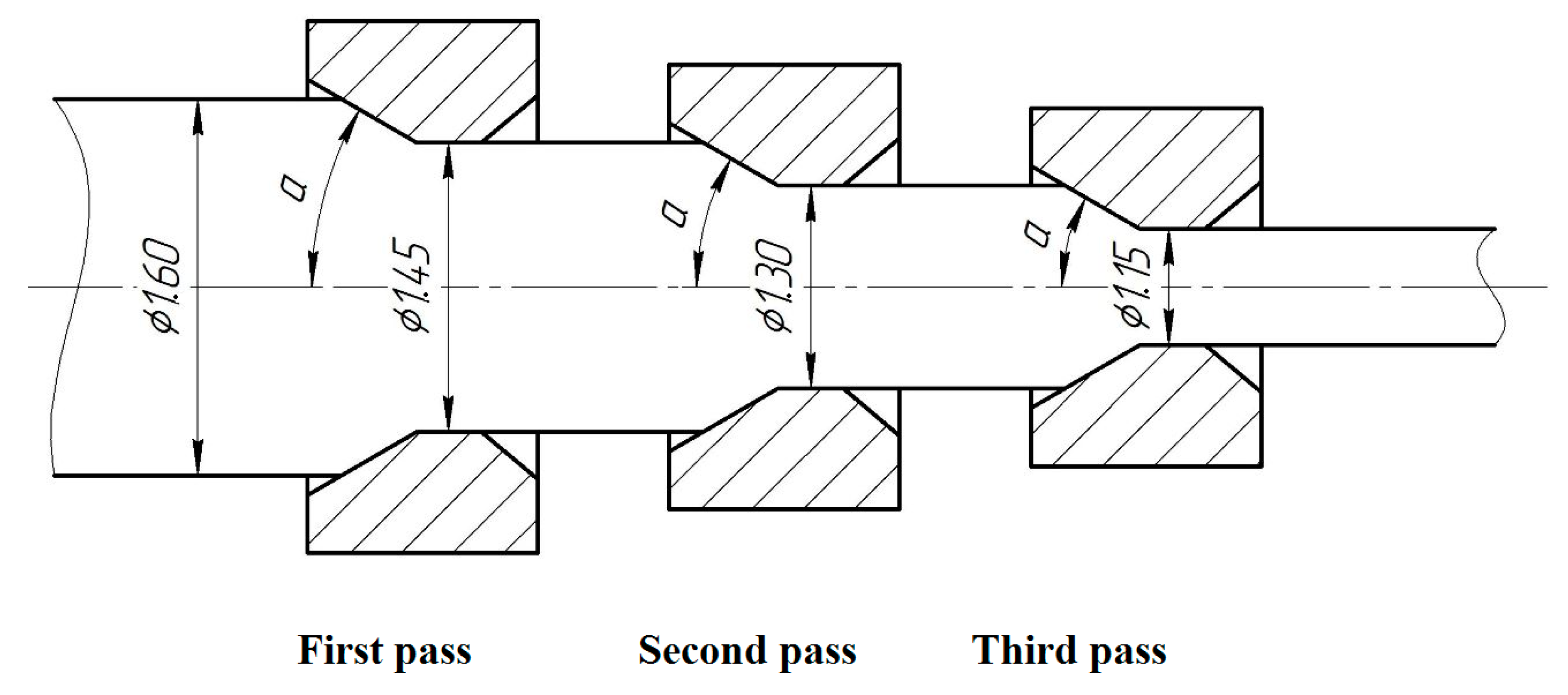
| Series | Initial Diameter of Wire, mm | Final Diameter of Wire, mm | α, deg | Friction Conditions |
|---|---|---|---|---|
| 1.1 | 1.6 | 1.45 | 4 | s |
| 2.1 | 1.45 | 1.3 | ||
| 3.1 | 1.3 | 1.15 | ||
| 1.2 | 1.6 | 1.45 | 5 | s |
| 2.2 | 1.45 | 1.3 | ||
| 3.2 | 1.3 | 1.15 | ||
| 1.3 | 1.6 | 1.45 | 4 | h |
| 2.3 | 1.45 | 1.3 | ||
| 3.3 | 1.3 | 1.15 | ||
| 1.4 | 1.6 | 1.45 | 5 | h |
| 2.4 | 1.45 | 1.3 | ||
| 3.4 | 1.3 | 1.15 |
| Die Semiangle | First Pass | Second Pass | Third Pass |
|---|---|---|---|
| α = 4° | 10.5 μm | 8.8 μm | 6.3 μm |
| α = 5° | 7.2 μm | 6.8 μm | 6.3 μm |
| Die Semiangle | First Pass | Second Pass | Third Pass |
|---|---|---|---|
| α = 4° | 8.4 μm | 5.6 μm | 6.3 μm |
| α = 5° | 8.8 μm | 9.3 μm | 9.7 μm |
| α deg | Pass | (s) | (h) | ||
|---|---|---|---|---|---|
| t, μm | R, μm | t, μm | R, μm | ||
| 4 | 1st | 10.5 | 1.9 | 8.4 | 1.4 |
| 2nd | 8.8 | 1.2 | 5.6 | 1.0 | |
| 3rd | 6.3 | 1.4 | 6.3 | 1.1 | |
| 5 | 1st | 7.2 | 2.7 | 8.8 | 1.0 |
| 2nd | 6.8 | 1.1 | 9.3 | 1.3 | |
| 3rd | 6.3 | 1.0 | 9.7 | 1.9 | |
Publisher’s Note: MDPI stays neutral with regard to jurisdictional claims in published maps and institutional affiliations. |
© 2020 by the authors. Licensee MDPI, Basel, Switzerland. This article is an open access article distributed under the terms and conditions of the Creative Commons Attribution (CC BY) license (http://creativecommons.org/licenses/by/4.0/).
Share and Cite
Stolyarov, A.; Polyakova, M.; Atangulova, G.; Alexandrov, S. Effect of Die Angle and Frictional Conditions on Fine Grain Layer Generation in Multipass Drawing of High Carbon Steel Wire. Metals 2020, 10, 1462. https://doi.org/10.3390/met10111462
Stolyarov A, Polyakova M, Atangulova G, Alexandrov S. Effect of Die Angle and Frictional Conditions on Fine Grain Layer Generation in Multipass Drawing of High Carbon Steel Wire. Metals. 2020; 10(11):1462. https://doi.org/10.3390/met10111462
Chicago/Turabian StyleStolyarov, Alexey, Marina Polyakova, Guzel Atangulova, and Sergei Alexandrov. 2020. "Effect of Die Angle and Frictional Conditions on Fine Grain Layer Generation in Multipass Drawing of High Carbon Steel Wire" Metals 10, no. 11: 1462. https://doi.org/10.3390/met10111462