Development of a TiNbTaMoZr-Based High Entropy Alloy with Low Young´s Modulus by Mechanical Alloying Route

 ,
,  and
and 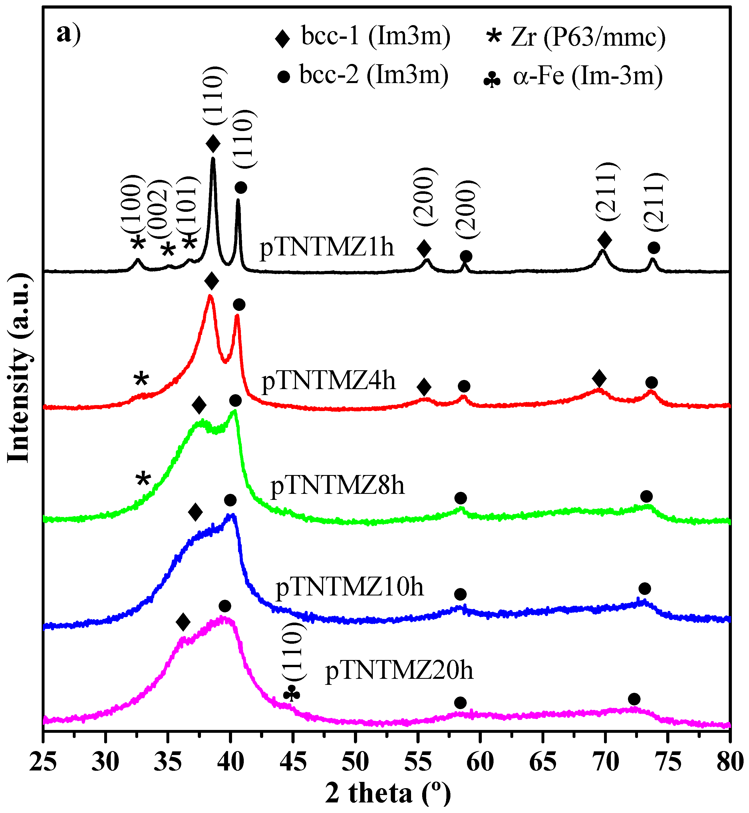
Abstract
:1. Introduction
2. Experimental Procedure
2.1. Development of the TiNbTaMoZr-Based HEA.
2.2. Microstructural Characterization of the TiNbTaMoZr-Based HEA.
2.3. Micromechanical Behavior of the TiNbTaMoZr-Based HEA.
3. Results and Discussion
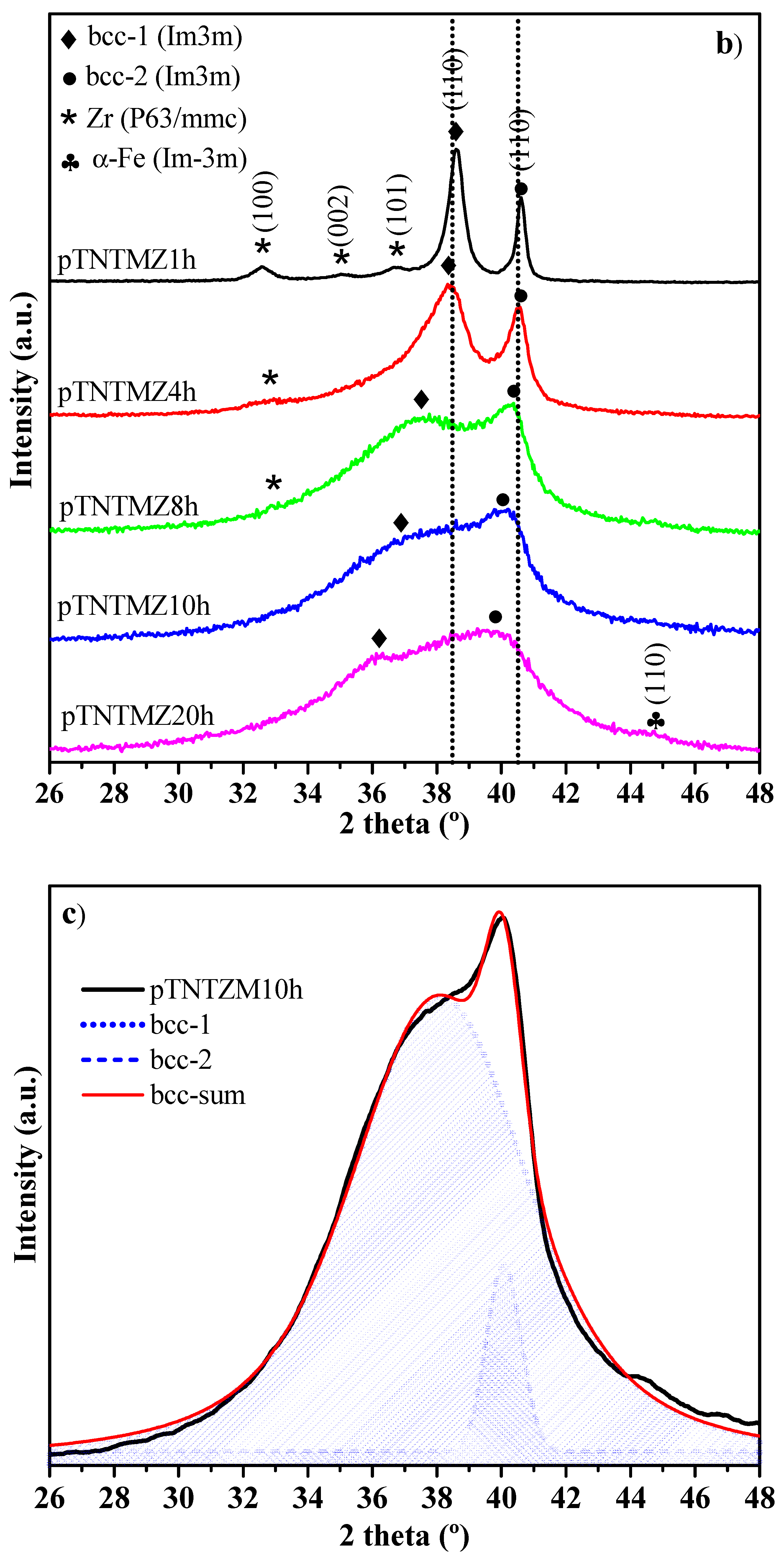
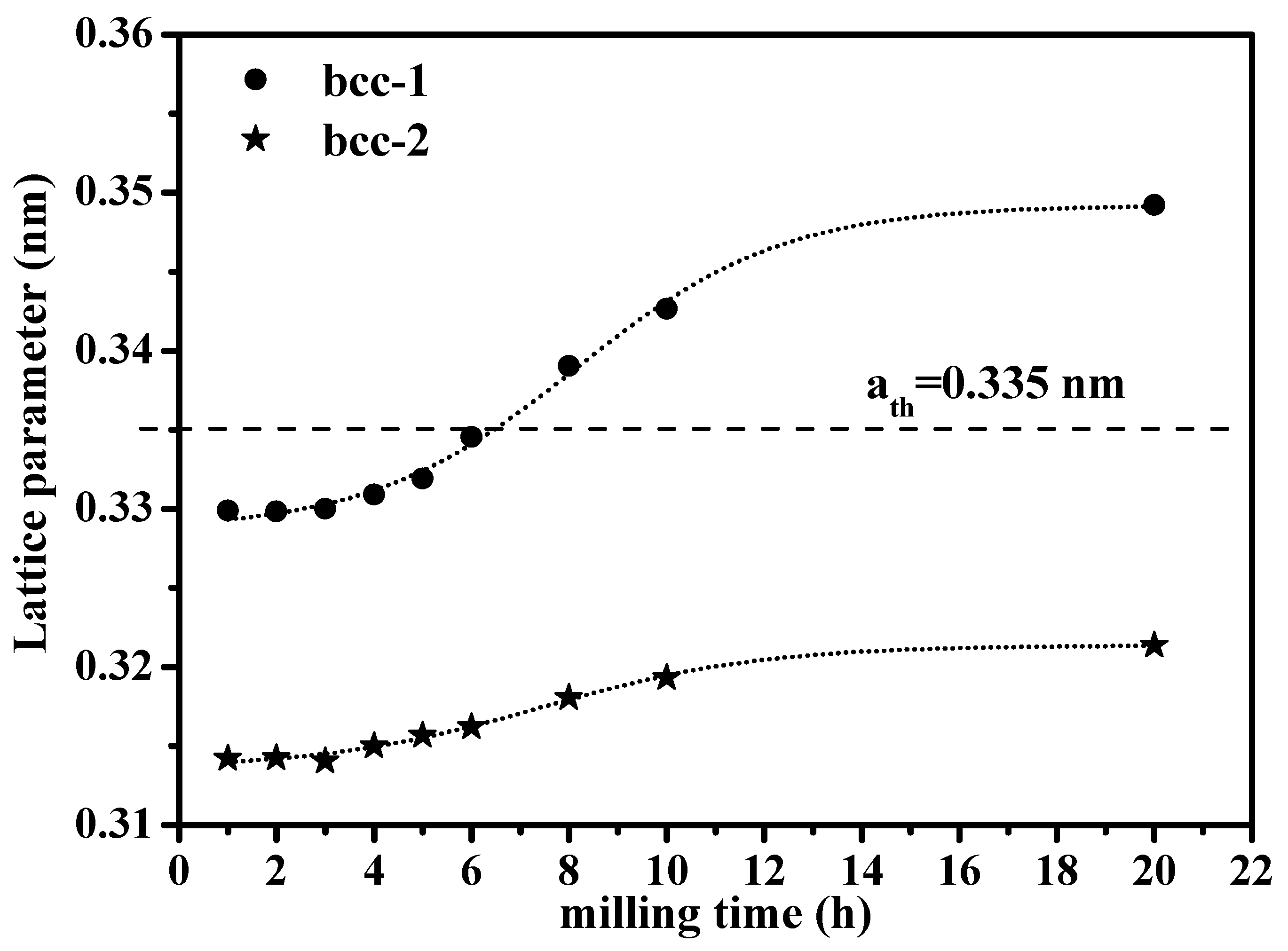
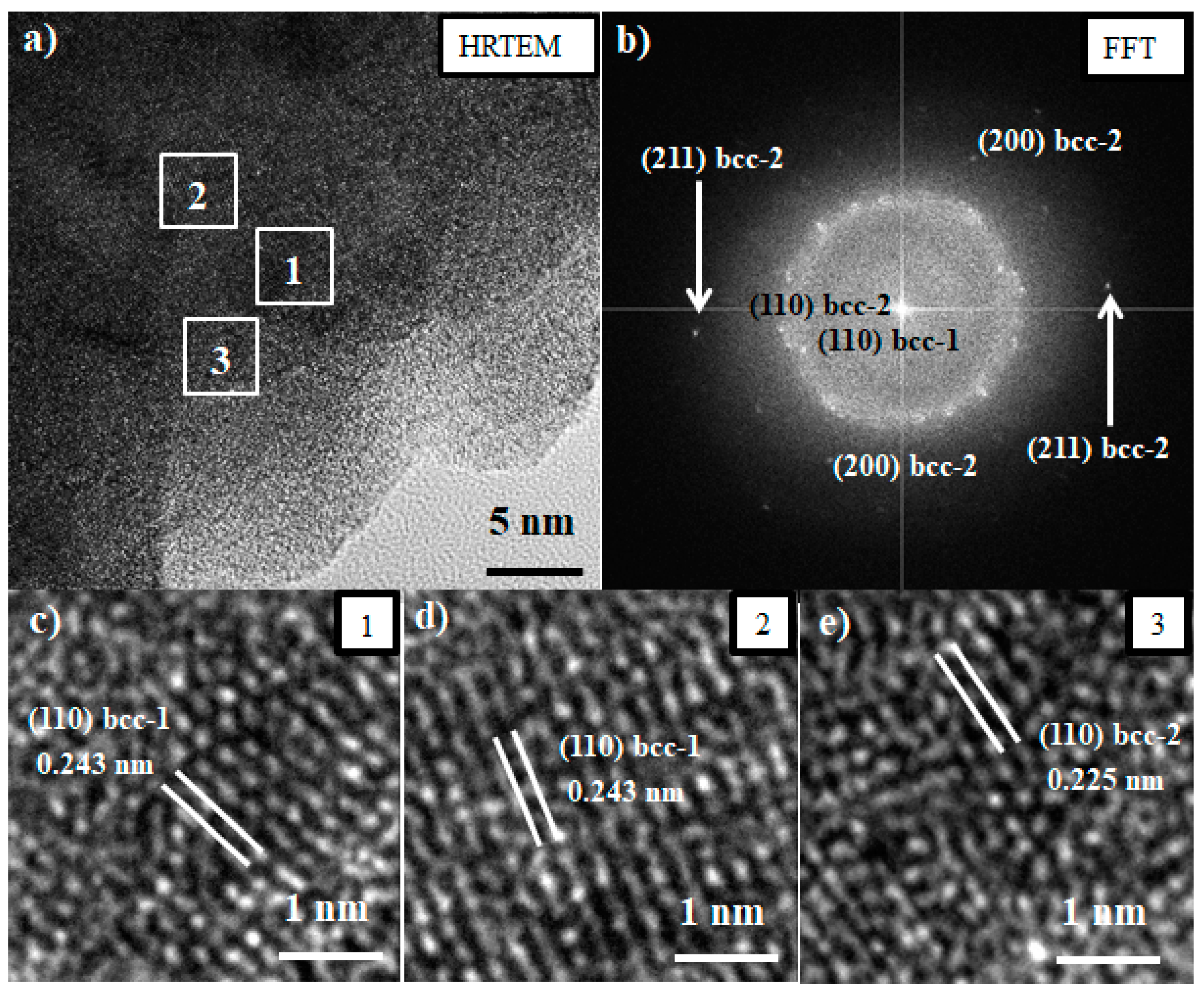
3.1. Synthesis and Characterization of the TiNbTaMoZr-Based HEA.
3.2. Consolidation of the TiNbTaMoZr-Based HEA.
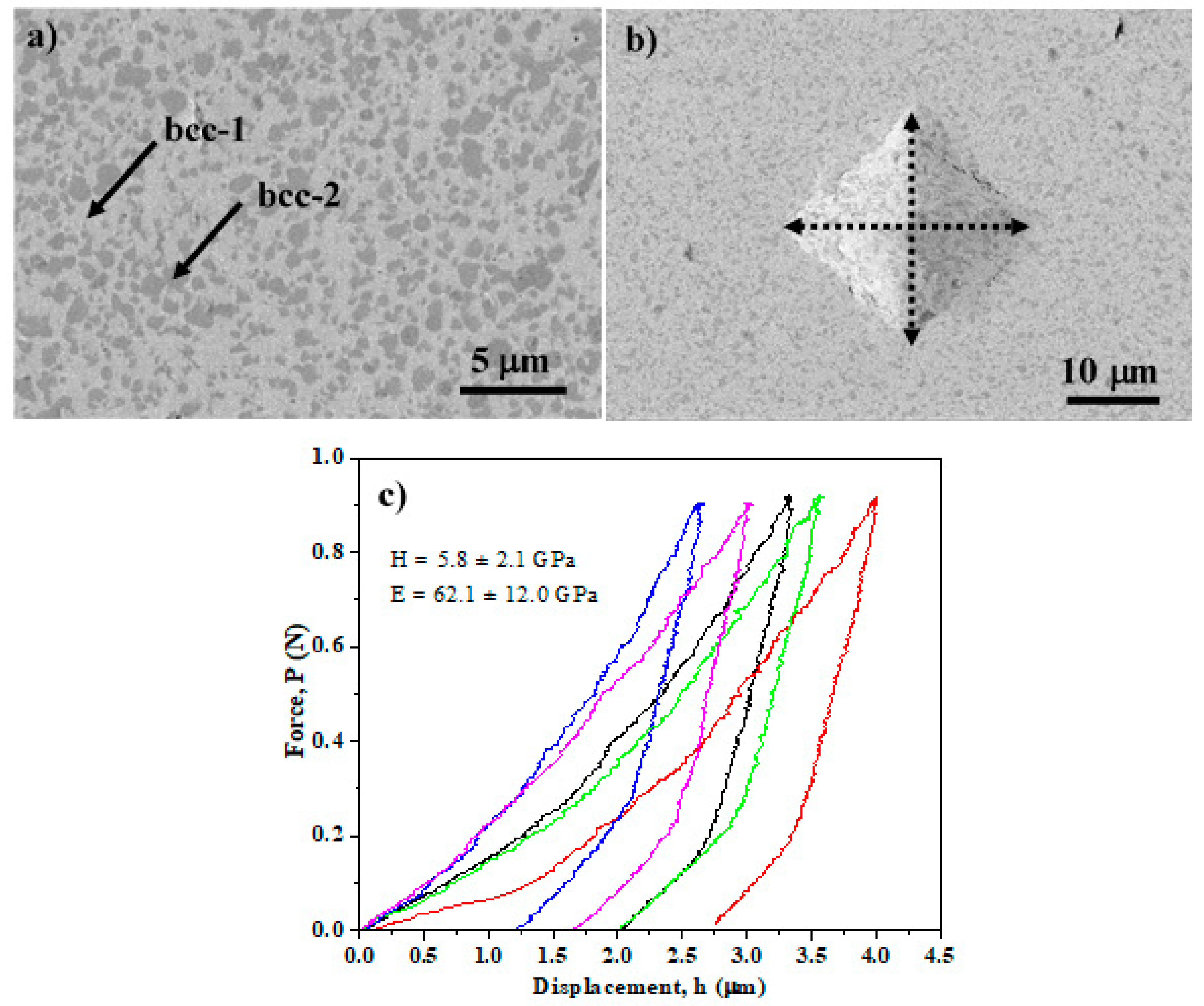
3.3. Micromechanical Behavior of the TiNbTaMoZr-Based HEA.
4. Conclusions
Author Contributions
Funding
Acknowledgments
Conflicts of Interest
References
- Unnithan, A.R.; Arathyram, R.; Kim, C.S. Electrospinning of Polymers for Tissue Engineering. Nanotechnol. Appl. Tissue Eng. 2015, 45–55. [Google Scholar] [CrossRef]
- Yeh, J.-W. Alloy Design Strategies and Future Trends in High-Entropy Alloys. JOM 2013, 65, 1759–1771. [Google Scholar] [CrossRef]
- Zhang, Y.; Zhou, Y.J.; Lin, J.P.; Chen, G.L.; Liaw, P.K. Solid-Solution Phase Formation Rules for Multi-component Alloys. Adv. Eng. Mater. 2008, 10, 534–538. [Google Scholar] [CrossRef]
- Guo, S.; Hu, Q.; Ng, C.; Liu, C. More than entropy in high-entropy alloys: Forming solid solutions or amorphous phase. Intermettalics 2013, 41, 96–103. [Google Scholar] [CrossRef]
- Ye, Y.; Wang, Q.; Lu, J.; Liu, C.; Yang, Y. High-entropy alloy: Challenges and prospects. Mater. Today 2016, 19, 349–362. [Google Scholar] [CrossRef]
- Pickering, E.J.; Jones, N.G. High-entropy alloys: A critical assessment of their founding principles and future prospects. Int. Mater. Rev. 2016, 61, 183–202. [Google Scholar] [CrossRef] [Green Version]
- Cantor, B.; Chang, I.; Knight, P.; Vincent, A. Microstructural development in equiatomic multicomponent alloys. Mater. Sci. Eng. A 2004, 375, 213–218. [Google Scholar] [CrossRef]
- Senkov, O.; Wilks, G.; Miracle, D.; Chuang, C.; Liaw, P. Refractory high-entropy alloys. Intermettalics 2010, 18, 1758–1765. [Google Scholar] [CrossRef]
- Miracle, D.B.; Miller, J.D.; Senkov, O.; Woodward, C.; Uchic, M.D.; Tiley, J. Exploration and Development of High Entropy Alloys for Structural Applications. Entropy 2014, 16, 494–525. [Google Scholar] [CrossRef]
- Murty, B.; Yeh, J.; Ranganathan, S. High Entropy Alloys. High Entropy Alloys 2014, 10, 1–12. [Google Scholar]
- Li, Y.; Yang, C.; Zhao, H.; Qu, S.; Li, X.; Li, Y. New Developments of Ti-Based Alloys for Biomedical Applications. Materials. 2014, 7, 1709–1800. [Google Scholar] [CrossRef] [Green Version]
- Agrawal, C.M. Reconstructing the human body using biomaterials. JOM 1998, 50, 31–35. [Google Scholar] [CrossRef]
- Shi, L.; Wang, L.; Duan, Y.; Lei, W.; Wang, Z.; Li, J.; Fan, X.; Li, X.; Li, S.; Guo, Z. The Improved Biological Performance of a Novel Low Elastic Modulus Implant. PLoS ONE 2013, 8, e55015. [Google Scholar] [CrossRef]
- Geetha, M.; Singh, A.; Asokamani, R.; Gogia, A. Ti based biomaterials, the ultimate choice for orthopaedic implants – A review. Prog. Mater. Sci. 2009, 54, 397–425. [Google Scholar] [CrossRef]
- Calin, M.; Gebert, A.; Ghinea, A.C.; Gostin, P.F.; Abdi, S.; Mickel, C.; Eckert, J. Designing biocompatible Ti-based metallic glasses for implant applications. Mater. Sci. Eng. C 2013, 33, 875–883. [Google Scholar] [CrossRef] [PubMed]
- Matsuno, H. Biocompatibility and osteogenesis of refractory metal implants, titanium, hafnium, niobium, tantalum and rhenium. Biomaterials 2001, 22, 1253–1262. [Google Scholar] [CrossRef]
- Hynowska, A.; Pellicer, E.; Fornell, J.; González, S.; Van Steenberge, N.; Suriñach, S.; Gebert, A.; Calin, M.; Eckert, J.; Baró, M.D.; et al. Nanostructured β-phase Ti–31.0Fe–9.0Sn and sub-μm structured Ti–39.3Nb–13.3Zr–10.7Ta alloys for biomedical applications: Microstructure benefits on the mechanical and corrosion performances. Mater. Sci. Eng. C 2012, 32, 2418–2425. [Google Scholar] [CrossRef]
- Meng, Q.; Guo, S.; Liu, Q.; Hu, L.; Zhao, X. A β-type TiNbZr alloy with low modulus and high strength for biomedical applications. Prog. Nat. Sci. 2014, 24, 157–162. [Google Scholar] [CrossRef] [Green Version]
- Long, M.; Rack, H. Titanium alloys in total joint replacement—A materials science perspective. Biomaterials 1998, 19, 1621–1639. [Google Scholar] [CrossRef]
- Hussein, A.H.; Gepreel, M.A.-H.; Gouda, M.K.; Hefnawy, A.M.; Kandil, S.H. Biocompatibility of new Ti–Nb–Ta base alloys. Mater. Sci. Eng. C 2016, 61, 574–578. [Google Scholar] [CrossRef]
- Chicardi, E.; Gutiérrez-González, C.; Sayagués, M.; García-Garrido, C. Development of a novel TiNbTa material potentially suitable for bone replacement implants. Mater. Des. 2018, 145, 88–96. [Google Scholar] [CrossRef]
- Chicardi, E.; García-Garrido, C.; Sayagués, M.; Torres, Y.; Amigó, V.; Aguilar, C. Development of a novel fcc structure for an amorphous-nanocrystalline Ti-33Nb-4Mn (at.%) ternary alloy. Mater. Charact. 2018, 135, 46–56. [Google Scholar] [CrossRef]
- Singh, S.; Wanderka, N.; Murty, B.; Glatzel, U.; Banhart, J. Decomposition in multi-component AlCoCrCuFeNi high-entropy alloy. Acta Mater. 2011, 59, 182–190. [Google Scholar] [CrossRef]
- Suryanarayana, C. Mechanical alloying and milling. Prog. Mater. Sci. 2001, 46, 1–184. [Google Scholar] [CrossRef]
- Wang, S.-P.; Xu, J. TiZrNbTaMo high-entropy alloy designed for orthopedic implants: As-cast microstructure and mechanical properties. Mater. Sci. Eng. C 2017, 73, 80–89. [Google Scholar] [CrossRef] [PubMed]
- Todai, M.; Nagase, T.; Hori, T.; Matsugaki, A.; Sekita, A.; Nakano, T. Novel TiNbTaZrMo high-entropy alloys for metallic biomaterials. Scr. Mater. 2017, 129, 65–68. [Google Scholar] [CrossRef] [Green Version]
- Nagase, T.; Todai, M.; Hori, T.; Nakano, T. Microstructure of equiatomic and non-equiatomic Ti-Nb-Ta-Zr-Mo high-entropy alloys for metallic biomaterials. J. Alloy. Compd. 2018, 753, 412–421. [Google Scholar] [CrossRef]
- Popov, V.V.; Katz-Demyanetz, A.; Koptyug, A.; Bamberger, M. Selective electron beam melting of Al0.5CrMoNbTa0.5 high entropy alloys using elemental powder blend. Heliyon 2019, 5, e01188. [Google Scholar] [CrossRef] [Green Version]
- Oliver, W.; Pharr, G. Measurement of hardness and elastic modulus by instrumented indentation: Advances in understanding and refinements to methodology. J. Mater. Res. 2004, 19, 3–20. [Google Scholar] [CrossRef]
- Davis, J.R. Handbook of Materials for Medical Devices; ASM International: Cleveland, OH, USA, 2003. [Google Scholar]
- Li, Y.; Jahr, H.; Lietaert, K.; Pavanram, P.; Yilmaz, A.; Fockaert, L.; Leeflang, M.; Pouran, B.; Gonzalez-Garcia, Y.; Weinans, H.; et al. Additively manufactured biodegradable porous iron. Acta Biomater. 2018, 77, 380–393. [Google Scholar] [CrossRef]
- Zhu, S.; Huang, N.; Xu, L.; Zhang, Y.; Liu, H.; Sun, H.; Leng, Y. Biocompatibility of pure iron: In vitro assessment of degradation kinetics and cytotoxicity on endothelial cells. Mater. Sci. Eng. C 2009, 29, 1589–1592. [Google Scholar] [CrossRef]
- Liu, B.; Zheng, Y. Effects of alloying elements (Mn, Co, Al, W, Sn, B, C and S) on biodegradability and in vitro biocompatibility of pure iron. Acta Biomater. 2011, 7, 1407–1420. [Google Scholar] [CrossRef]
- Gorsse, S.; Nguyen, M.; Senkov, O.; Miracle, D. Database on the mechanical properties of high entropy alloys and complex concentrated alloys. Data Brief 2018, 21, 2664–2678. [Google Scholar] [CrossRef] [PubMed]
- Senkov, O.; Senkova, S.; E Woodward, C.; Miracle, D. Low-density, refractory multi-principal element alloys of the Cr–Nb–Ti–V–Zr system: Microstructure and phase analysis. Acta Mater. 2013, 61, 1545–1557. [Google Scholar] [CrossRef]
- Senkov, O.; Senkova, S.; Woodward, C. Effect of aluminum on the microstructure and properties of two refractory high-entropy alloys. Acta Mater. 2014, 68, 214–228. [Google Scholar] [CrossRef]
- Wu, Y.; Cai, Y.; Chen, X.; Wang, T.; Si, J.; Wang, L.; Wang, Y.; Hui, X. Phase composition and solid solution strengthening effect in TiZrNbMoV high-entropy alloys. Mater. Des. 2015, 83, 651–660. [Google Scholar] [CrossRef]
- Toda-Caraballo, I.; Rivera-Díaz-Del-Castillo, P.E. Modelling solid solution hardening in high entropy alloys. Acta Mater. 2015, 85, 14–23. [Google Scholar] [CrossRef]
- Gan, J.; Berndt, C. Plasma Surface Modification of Metallic Biomaterials. In Surface Coating and Modification of Metallic Biomaterials; Elsevier BV: Amsterdam, The Netherlands, 2015; pp. 103–157. [Google Scholar]
- Breme, J.; Eisenbarth, E.; Biehl, V. Titanium and its Alloys for Medical Applications. In Titanium and Titanium Alloys; Wiley: Hoboken, NJ, USA, 2005; pp. 423–451. [Google Scholar]
- Ibrahim, H.; Esfahani, S.N.; Poorganji, B.; Dean, D.; Elahinia, M. Resorbable bone fixation alloys, forming, and post-fabrication treatments. Mater. Sci. Eng. C 2017, 70, 870–888. [Google Scholar] [CrossRef] [Green Version]
- Kolli, R.P.; Devaraj, A. A Review of Metastable Beta Titanium Alloys. Metabolism 2018, 8, 506. [Google Scholar] [CrossRef] [Green Version]
- Niinomi, M.; Liu, Y.; Nakai, M.; Liu, H.; Li, H. Biomedical titanium alloys with Young’s moduli close to that of cortical bone. Regen. Biomater. 2016, 3, 173–185. [Google Scholar] [CrossRef] [Green Version]
- Wang, Z.; Baker, I.; Guo, W.; Poplawsky, J.D. The effect of carbon on the microstructures, mechanical properties, and deformation mechanisms of thermo-mechanically treated Fe40.4Ni11.3Mn34.8Al7.5Cr6 high entropy alloys. Acta Mater. 2017, 126, 346–360. [Google Scholar] [CrossRef] [Green Version]
- Li, Z.; Tasan, C.C.; Springer, H.; Gault, B.; Raabe, D. Interstitial atoms enable joint twinning and transformation induced plasticity in strong and ductile high-entropy alloys. Sci. Rep. 2017, 7, 40704. [Google Scholar] [CrossRef]
- Eleti, R.R.; Klimova, M.; Tikhonovsky, M.; Stepanov, N.; Zherebtsov, S. Exceptionally high strain-hardening and ductility due to transformation induced plasticity effect in Ti-rich high-entropy alloys. Sci. Rep. 2020, 10, 1–8. [Google Scholar] [CrossRef] [PubMed]


Publisher’s Note: MDPI stays neutral with regard to jurisdictional claims in published maps and institutional affiliations. |
© 2020 by the authors. Licensee MDPI, Basel, Switzerland. This article is an open access article distributed under the terms and conditions of the Creative Commons Attribution (CC BY) license (http://creativecommons.org/licenses/by/4.0/).
Share and Cite
Normand, J.; Moriche, R.; García-Garrido, C.; Sepúlveda Ferrer, R.E.; Chicardi, E. Development of a TiNbTaMoZr-Based High Entropy Alloy with Low Young´s Modulus by Mechanical Alloying Route. Metals 2020, 10, 1463. https://doi.org/10.3390/met10111463
Normand J, Moriche R, García-Garrido C, Sepúlveda Ferrer RE, Chicardi E. Development of a TiNbTaMoZr-Based High Entropy Alloy with Low Young´s Modulus by Mechanical Alloying Route. Metals. 2020; 10(11):1463. https://doi.org/10.3390/met10111463
Chicago/Turabian StyleNormand, Juliette, Rocío Moriche, Cristina García-Garrido, Ranier Enrique Sepúlveda Ferrer, and Ernesto Chicardi. 2020. "Development of a TiNbTaMoZr-Based High Entropy Alloy with Low Young´s Modulus by Mechanical Alloying Route" Metals 10, no. 11: 1463. https://doi.org/10.3390/met10111463