Article

Mechanical and Tribological Behavior of Austempered Ductile Iron (ADI) under Dry Sliding Conditions

1
School of Materials Science and Engineering, Xi’an University of Technology, Xi’an 710048, China
2
Shanxi Jianbang Casting Co., Ltd., Houma 043000, China
*
Author to whom correspondence should be addressed.
Lubricants 2023, 11(4), 182; https://doi.org/10.3390/lubricants11040182
Submission received: 1 March 2023 / Revised: 23 March 2023 / Accepted: 17 April 2023 / Published: 18 April 2023
(This article belongs to the Special Issue Frictional Behavior and Wear Performance of Cast Irons)

Abstract

:
In the current investigation, a vertically continuous casting technique was used to produce a ductile iron pipe. The ductile iron was austempered, and the tribological behavior of austempered ductile iron (ADI) was examined under various service conditions. The finding demonstrated that ADI’s tribological behaviors were significantly affected by normal loads and sliding speeds. Spheroidal graphite was preferential to be transferred from the matrix to the tribosurface in ADI under high normal loads, and high sliding speed accelerated the formation of the graphite lubricating layer on the tribosurface. Consequently, ADI’s friction coefficient dropped with the increase in normal load and sliding speed. When compared with the friction coefficient, the wear rate of ADI displayed a similar tendency in that it increased with an increase in normal load and reduced with an increase in sliding speed. The worn surface indicated that adhesive wear at low sliding speeds and abrasive wear at high sliding speeds were the primary wear mechanisms for ADI.

Graphical Abstract

1. Introduction

A good combination of strength and toughness of austempered ductile iron (ADI) is required for high-performance applications [1], which is governed by the matrix microstructure. The ADI matrix contains a retained austenite and acicular microstructure [2], which is referred to as ausferrite [3]. Transmission electron microscopy analysis confirms that the needle-like phase consists of α phase and γ phase at the nanometric scale, both of which contain supersaturated carbon [4]. The microstructure and carbon content in stabilized austenite of ADI are closely related to the austempering temperature [5]. More retained austenite and a coarse ausferrite microstructure could be obtained in ADI when austempered at high temperatures [6], which directly affects the mechanical response of ADI [7,8]. For instance, nanoscale α phase was produced by austempering ductile iron at 300 °C, which gave rise to an ultimate tensile strength higher than 1400 MPa [9]. However, the ADI austempered at 380 °C contained a large amount of blocky austenite, resulting in a tensile strength lower than 1000 MPa [10]. Moreover, ADI was given a two-step austempering treatment as opposed to the normal single-step treatment, producing a significantly finer microstructure and a yield strength of up to 1455 MPa [11].
When used as transmission parts, the spheroidal graphite in ductile iron is easily transferred to the tribosurface and forms a lubricating layer [12], which significantly lowers the friction coefficient and increases wear resistance [10,13]. Hence, ductile iron has been used in guideways or gear that requires good wear properties. The wear behavior of ductile iron was closely related to service conditions [14]. For example, adhesive wear was observed at the early stage of wear, and oxidative wear would predominate as wear time increased [14]; under compressive stress greater than 40 MPa, the friction coefficient of gray cast iron was increased from 0.0043 to 0.7 with the increase in compressive stress, while the value remained nearly constant at 0.0043 under the compressive stress lower than 40 MPa [15]. Adhesive wear prevailed at 25–200 °C for spheroidal graphite cast iron, and oxidative and adhesive wear coexisted at 400 °C [16].
It has been recommended that ADI is a prospective candidate to replace forged steels in the application of transmission parts because it has a good combination of mechanical qualities and wear resistance [9]. The mechanical properties of ADI have direct effects on tribological behavior [17]. Generally, the high strength of ADI benefits the improvement of wear resistance according to Archard’s law [18], but the graphite is hard to transfer to the tribosurface in ADI with a high strength, which is not good for the reduction of the friction coefficient [19]. Hence, a proper strength of ADI is preferred to enhance the wear resistance. Additionally, wear conditions of ADI have an important impact on its tribological behavior [20]. For example, adhesive and abrasive wear were thought to be the primary failure mechanisms for ADI under dry sliding wear conditions [10], but surface fatigue was also detected for ADI [21]; the introduction of carbides in the microstructure of ADI improved the wear resistance obviously [22]. The hardness of ADI was decreased with the increase in the austempering temperature, which gave rise to a reduction in the friction coefficient under the effects of high normal load [10]. Moreover, it has been demonstrated that martensite can be induced from the residual austenite in ADI, which enhances the hardness and improves wear resistance, increasing hardness and improving wear resistance [19,23]. ADI with the volume fraction of carbon-rich austenite higher than 30% exhibited a better wear resistance at high wear loads because more austenite could be induced to transform into martensite [19]. However, some investigations indicated that only very small amounts of the stabilized austenite in ADI could be transformed into martensite due to its high mechanical stability [6]. Hence, understanding the tribological behavior of ADI under different service conditions is critical for its application. Unfortunately, a thorough investigation of ADI’s tribological behavior under various service situations has not yet been conducted. In order to provide suggestions for the use of ADI, the effects of sliding speed and applied stresses on the tribological behavior of ADI are therefore investigated in the current work.

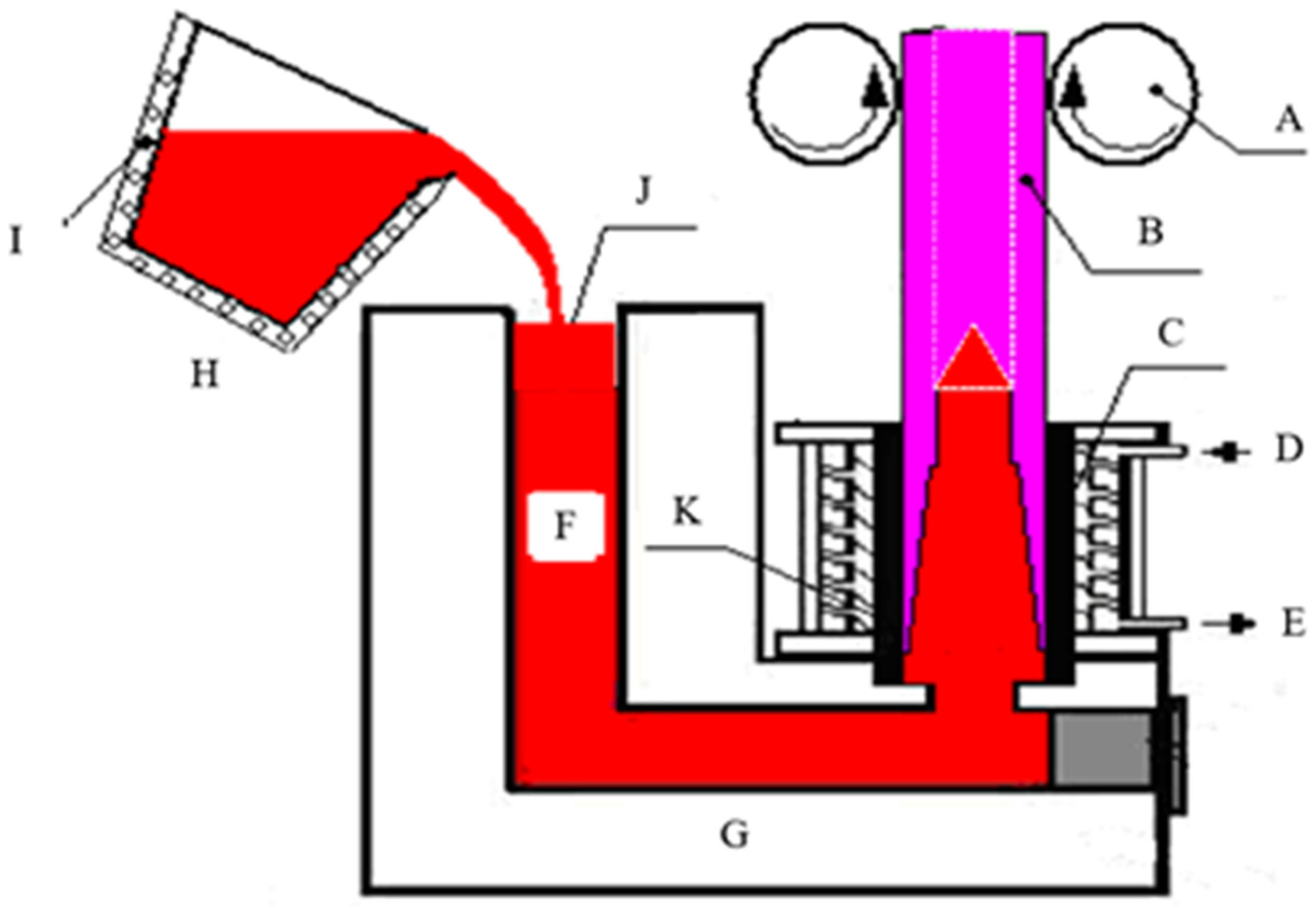
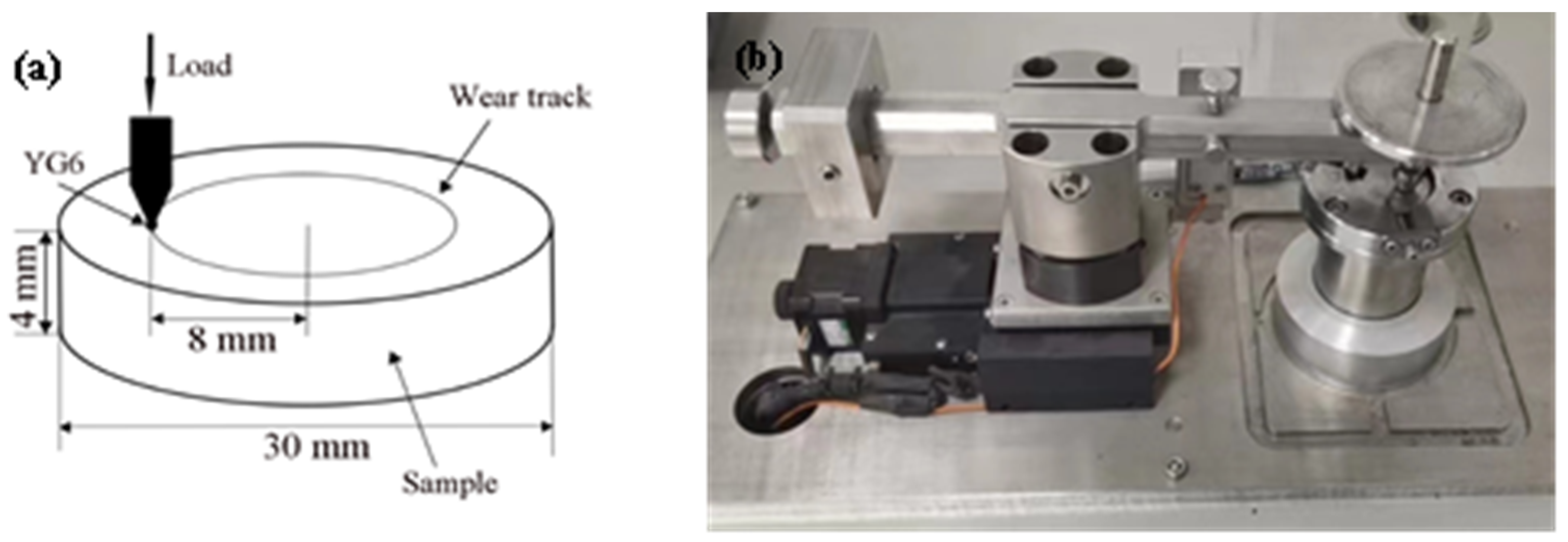
2. Experimental Procedure

The vertically continuous casting method was used to fabricate a hollow ductile iron pipe with a diameter of 200 mm and a thickness of 20 mm. The detailed fabrication procedure can be described as follows. An amount of 60% pig iron, 20% low-carbon steel scrap, and 20% ductile iron return charge were used as raw materials. Firstly, the raw materials were melted in a medium-frequency induction furnace and the chemical composition of iron melt was determined to be 3.30 ± 0.05% C, 1.6 ± 0.05% Si, Mn ≤ 0.2%, P ≤ 0.015%, S ≤ 0.015%, 0.6% Cu, Ni ≤ 0.6%, Cr ≤ 0.3%, and the balance Fe. The iron melt was held at 1530 °C for 20 min and then poured into a 300 kg container (H in Figure 1), in which 4.5 kg of Ce–Mg nodularizer was placed in advance. When the spheroidizing reaction finished, 3.0 kg of 75% ferrosilicon inoculant was added for inoculation. After nodularization and inoculation treatment, the temperature of the iron melt was approximately 1460 °C, and the iron melt contained approximately 2.60% Si and 0.035–0.045% Mg. Then, iron melt was poured into a continuous casting furnace (G in Figure 1). Seeding was positioned in the crystallizer (C in Figure 1). When the iron melt contacted the seeding on the crystallizer, it solidifies. With the drawing machine (A in Figure 1) working at the speed of 50 mm per step and held for 8 s every step, a casting pipe could be obtained. The fabricated casting pipe is shown in Figure 2. It can be seen that no obvious casting defects could be detected in the pipe. This casting method has been approved to be able to reduce impurities compared with horizontal continuous casting [24].
The chemical composition of the ductile iron was analyzed using a spark-type optical emission spectrometer (SPECTRO Analytical Instruments, Kleve, Germany), given in Table 1. Carbon concentration in austenite during austenization treatment was closely related to temperature, in which high carbon concentration was obtained with the increase in the austenizing temperature. High carbon concentration in austenite was beneficial for achieving a fine microstructure during austempering treatment. Therefore, the cut ductile cast-iron pipe was heated to 950 °C for austenizing treatment and held for 60 min. The austempering temperature was 300 °C, which is a commonly used temperature for ADI. The austenized samples were quenched into a salt bath consisting of 50% NaNO3 and 50% NaNO2 with a temperature of 300 °C and held for 30 min. The produced ADI was mechanically ground and polished followed by etching with 4% nital solution. An Olympus GX71 optical microscope (Olympus Corporation, Tokyo, Japan) and a VEGA3XMU scanning electron microscope (SEM, Tescan, Brno, Czech Republic) were employed to characterize the microstructure of ADI. The diameter of spheroidal graphite was measured using the software of Image J (National Institutes of Health). X-ray diffraction was conducted on an XRD-7000 diffractometer (SHIMADZU Corporation, Kyoto, Japan) with a scan speed of 4°/min and a scanning range of 30~90°. The volume fraction of retained austenite in ADI was determined by the direct contrast method using the integral intensities of (200), (111), and (220) planes of austenite. The lattice parameters of retained austenite were obtained by the following equation:
a γ = λ H 2 + K 2 + L 2 / 2 sin θ
where aγ is the lattice parameter of retained austenite, (HKL) is the diffraction planes corresponding to the diffraction peaks, θ is the diffraction angle, and λ is the wavelength. The carbon concentration of retained austenite was determined by the equation [16]:
aγ = 0.3548 + 0.0044 Cγ
where aγ is the lattice parameter of austenite in nanometers and is the carbon concentration of austenite in wt.%.
Samples were machined into a dimension with a diameter of 8 mm and a gauge length of 40 mm for tensile tests. Tensile tests were conducted at room temperature on a universal testing machine (HT-2402, Taihongda Instrument (Xiamen) Co., Ltd, Xiamen, China) with a crosshead speed of 1 mm/min. For each specimen, at least three tests were performed to keep repeatability.
The tribological properties of ADIs were conducted on a ball-on-disk tribotester, which was a homemade piece of equipment. The schematic diagram is presented in Figure 3. The ADI sample with a diameter of 30 mm and thickness of 4 mm was set as the disk, the initial roughness of which was measured to be approximately 0.09 μm via an OLS4000 confocal laser scanning microscope (Olympus Corporation, Tokyo, Japan). A hard metal YG6 WC ball with a hardness higher than 90 HRA was set as the ball. The diameter of the wear tack was 16 mm. In order to investigate the tribological behavior of ADI under different services, the rotating rates were set to be 100 r/min, 300 r/min, and 500 r/min and the normal loads were set to be 5 N, 10 N, and 20 N, respectively. For each condition, at least three samples were repeated. The sliding distance for all the wear tests was the same (500 m), which corresponded to the wear time of 6000 s, 2000 s, and 1200 s for the samples at the rotating rates of 100 r/min, 300 r/min, and 500 r/min. The weight of disks before and after wear tests were measured on a FA1004B analytic balance (Shanghai Sunny Hengping Scientific Instrument Co., Ltd, Shanghai, China) with a minimum resolution of 0.01 mg to determine weight loss. The value of the friction coefficient at steady stage was obtained by averaging the values of the repeated three curves.

3. Results

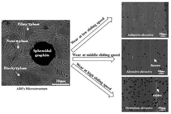
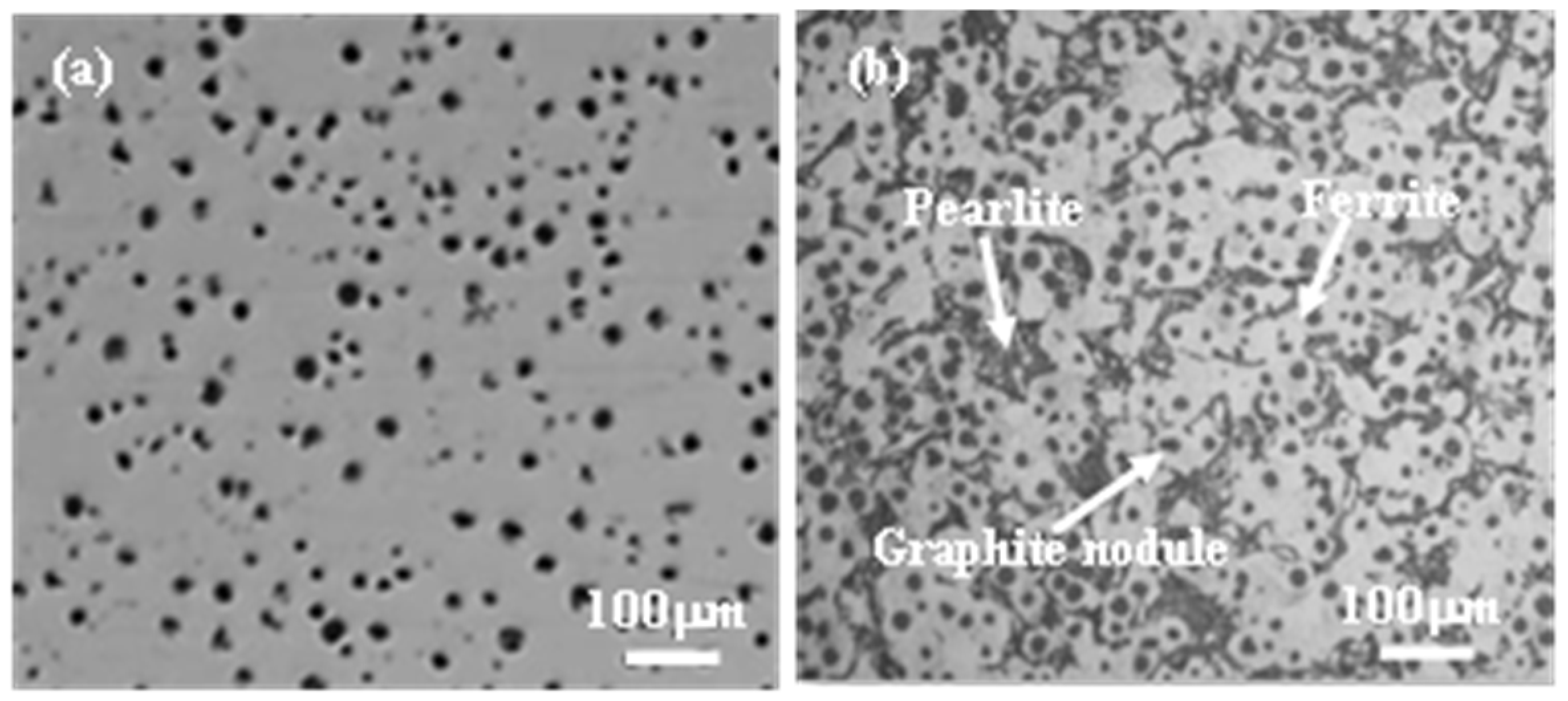
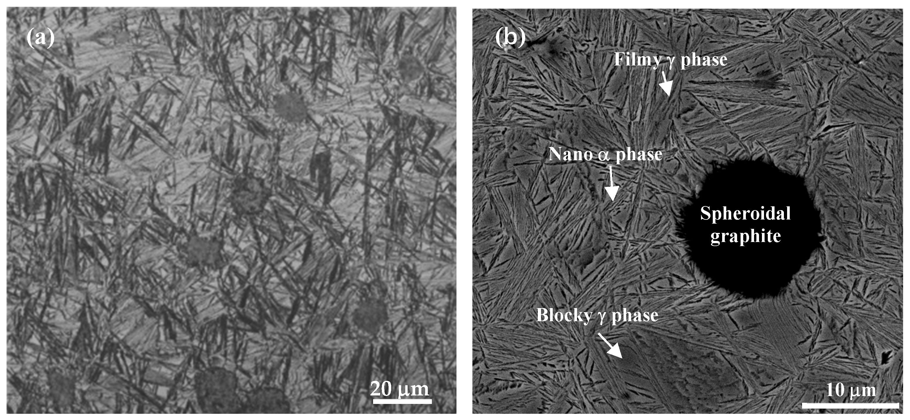
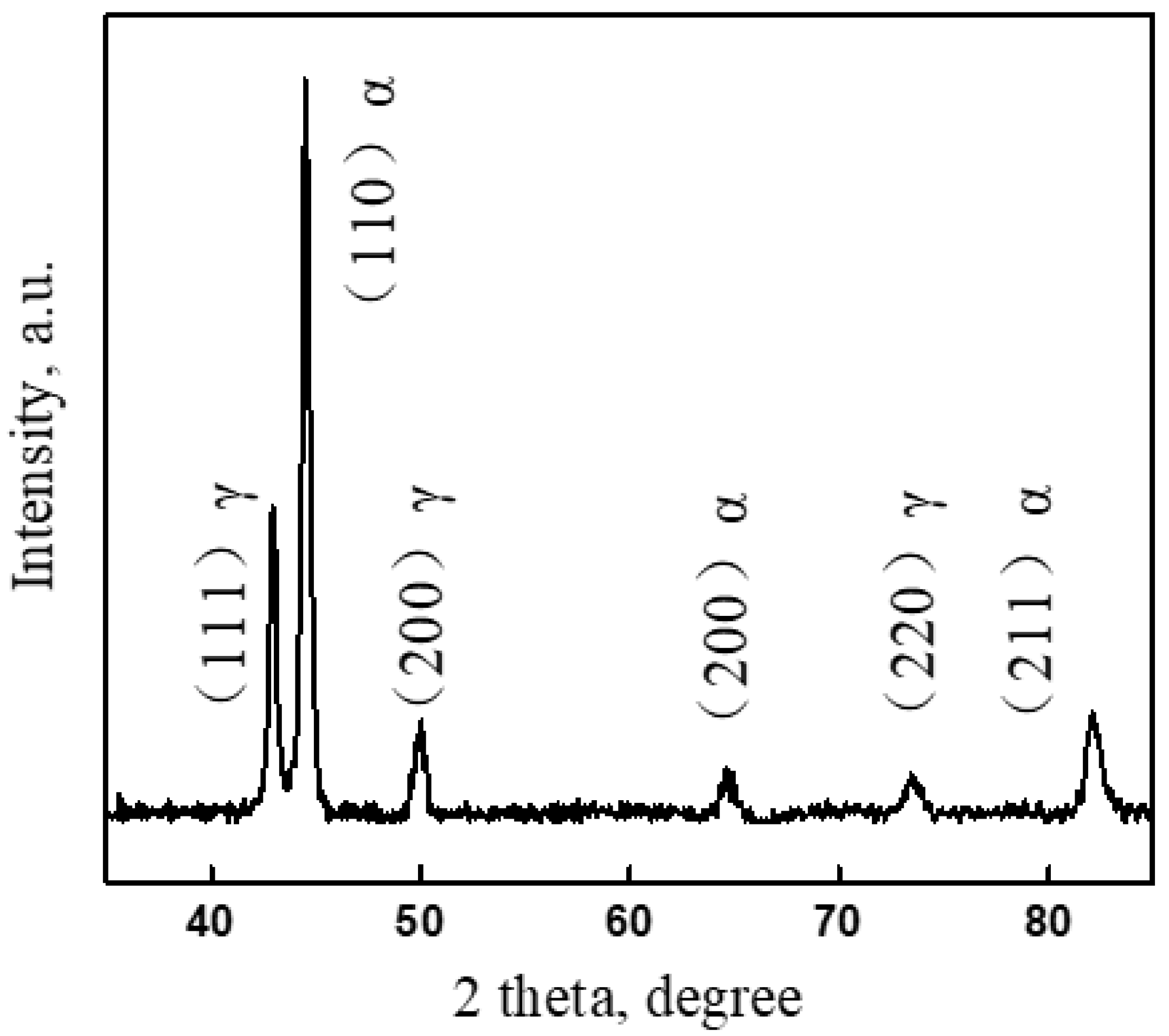
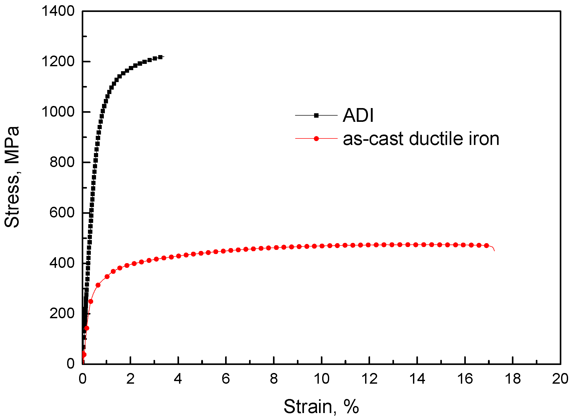
3.1. Microstructure and Mechanical Properties of ADI

Figure 4 shows the optical image of the as-cast ductile iron with and without etching. It was evident that spheroidal graphite was uniformly dispersed throughout the ductile iron matrix (Figure 4a). The volume fraction of graphite was estimated to be approximately 8.1%. Spheroidal graphite had a diameter ranging from 10 μm to 25 μm, and there were approximately 300/mm2. After etching treatment (Figure 4b), it could be observed that the ductile iron matrix was composed of ferrite and pearlite, with the ferrite distributing around the spheroidal graphite. This was a typical microstructure of ductile iron [8].
Figure 5 shows the microstructure of the ADI sample. The acicular microstructure could be detected (Figure 5a). SEM was used to clearly depict the matrix microstructure of the ADI, as seen in Figure 5b. The spheroidal graphite was surrounded by ausferrite, which was composed of acicular ferrite and retained austenite. It should be noted that retained austenite co-existed in the matrix with a large blocky shape far from graphite and a filmy shape distributed between nanoscale phases. During austempering, ferrite was preferentially nucleated in the vicinity of graphite or at the boundaries of austenite. Carbon atoms diffuse from ferrite to graphite nearby, but also to the surrounding austenite far from graphite as ferrite grew. As a result, the austenite located far from graphite has a high carbon concentration, increasing its stability. When the carbon concentration reaches a certain value, the untransformed austenite remains in the matrix at room temperature. As a result, the blocky austenite was retained in ADI, which was commonly detected in previous reports [2].
The ADI sample’s XRD patterns are displayed in Figure 6. The peaks of α and γ phases were detected. The volume fraction of γ phase according to XRD results was approximately 30%, and the carbon concentration in retained austenite was approimately 1.87%. The stability of retained austenite was sensitive to its carbon content [25,26]. Retained austenite that existed at room temperature has been detected in medium carbon bainitic steel containing approximately 0.39 carbon [27]. Therefore, the γ phase in the present study was stable because of the high carbon concentration in it. The microstructure containing nanoscale α phase and high-carbon γ phase was commonly observed in ADI [28].
Figure 7 shows the typical stress–strain curves of the as-cast ductile iron and ADI. The as-cast ductile iron exhibited a yield stress of 290 MPa, ultimate tensile strength of 470 MPa, and elongation of 16.9%. After austempering treatment, the strength was increased obviously. The yield strength of ADI was approximately 976 MPa and the ultimate tensile strength was approximately 1220 MPa. However, the ductility was drastically reduced compared with the as-cast counterpart. The elongation of ADI was approximately 3.4%. The matrix of the as-cast ductile iron was composed of ferrite and pearlite (Figure 4b), where ferrite was a very soft phase. Therefore, during the tensile test, ferrite was ready to be plastically deformed, which resulted in rather low strength. Nonetheless, the ausferrite in ADI contained nanoscale α phase and supersaturated γ phase. The phase boundaries between α and γ provide strength for ADI. It has been confirmed that carbon atoms were present in the ferrite in the bainite of bainitic steels [29]. The α phase in ausferrtie was obtained through austempering treatment, which was a similar treatment to the process of fabricating bainitic steel; thus, it is believed that small amounts of carbon atoms existed in α phase of ADI. Consequently, α phase should contain distortion energy and was a hard phase. Furthermore, approximately 1.87% carbon atoms in γ phase increased the strength of γ phase by solution strengthening. As a result, ADI exhibited a good strength because of carbon supersaturated in the matrix and fine microstructure.

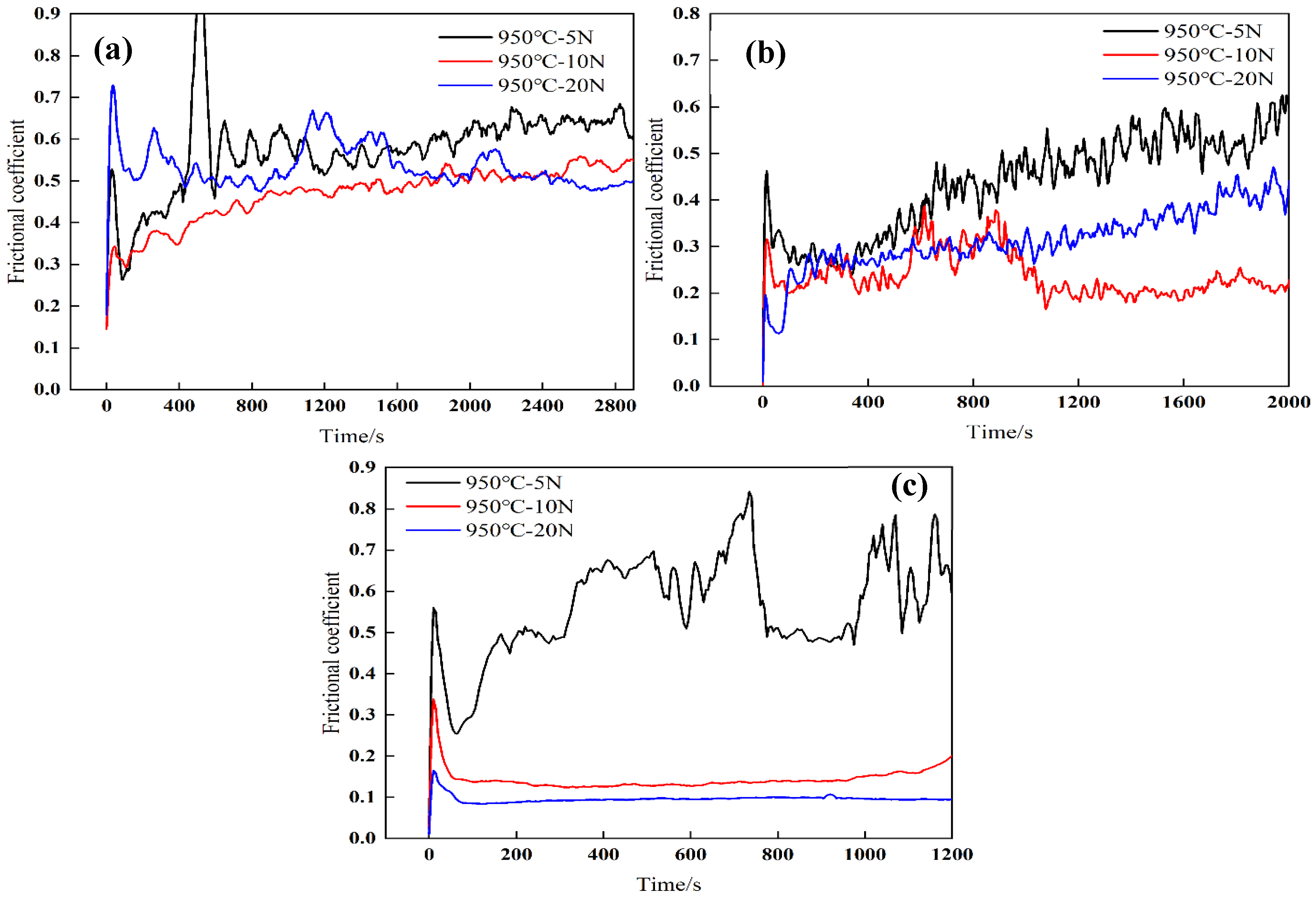
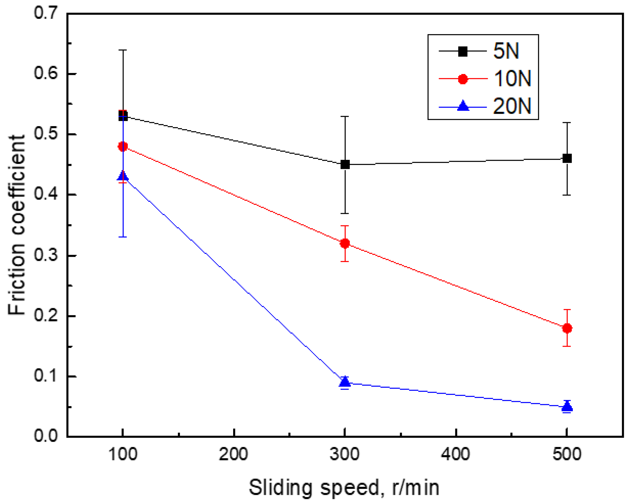
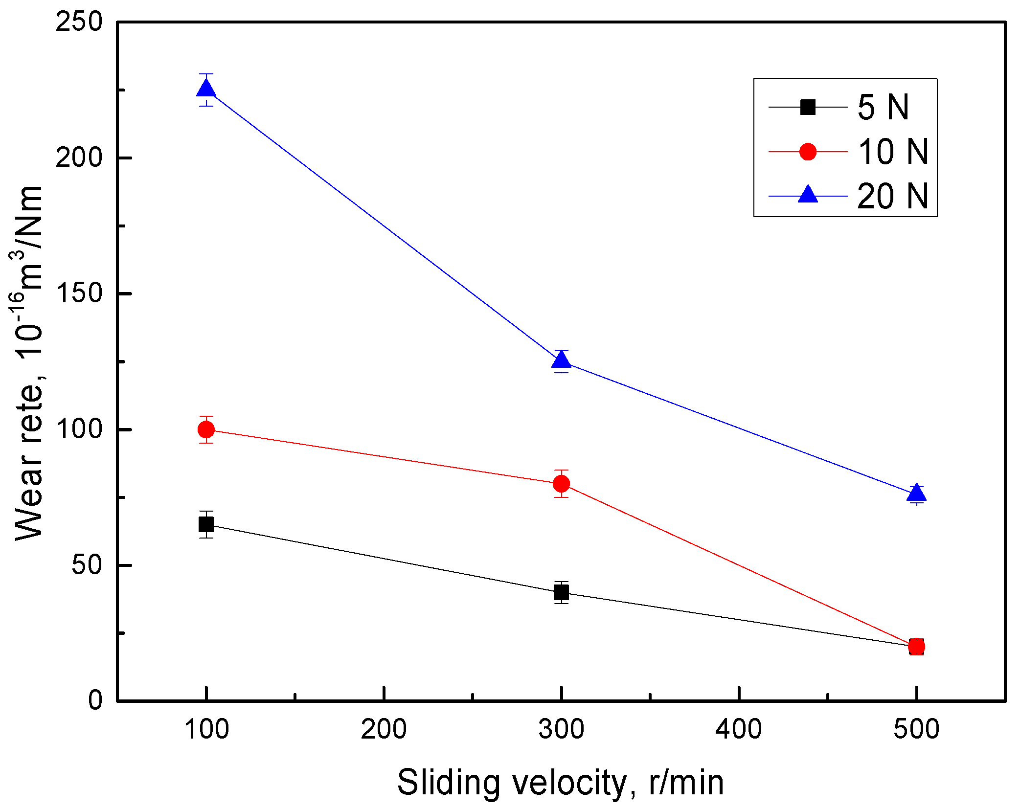
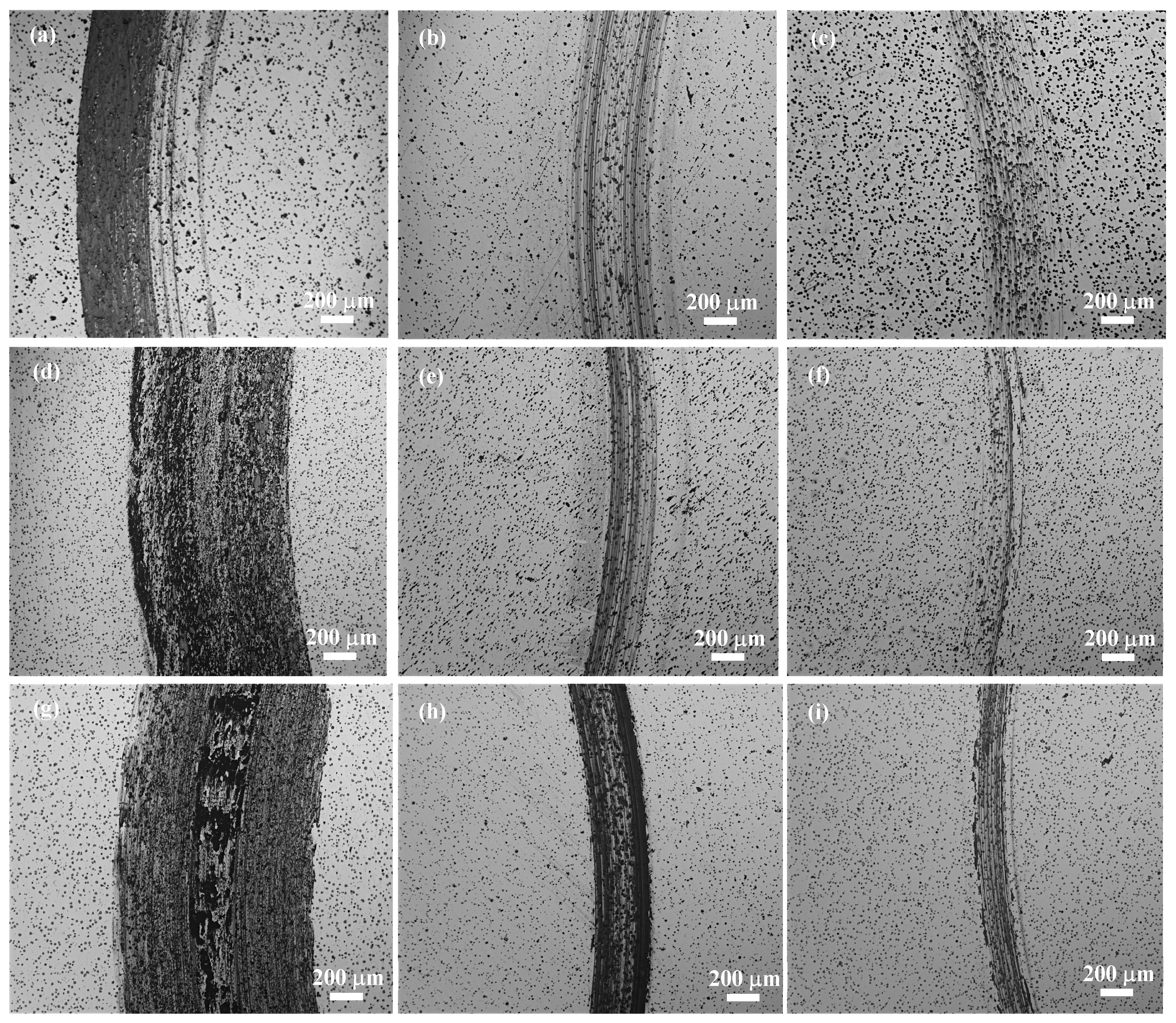
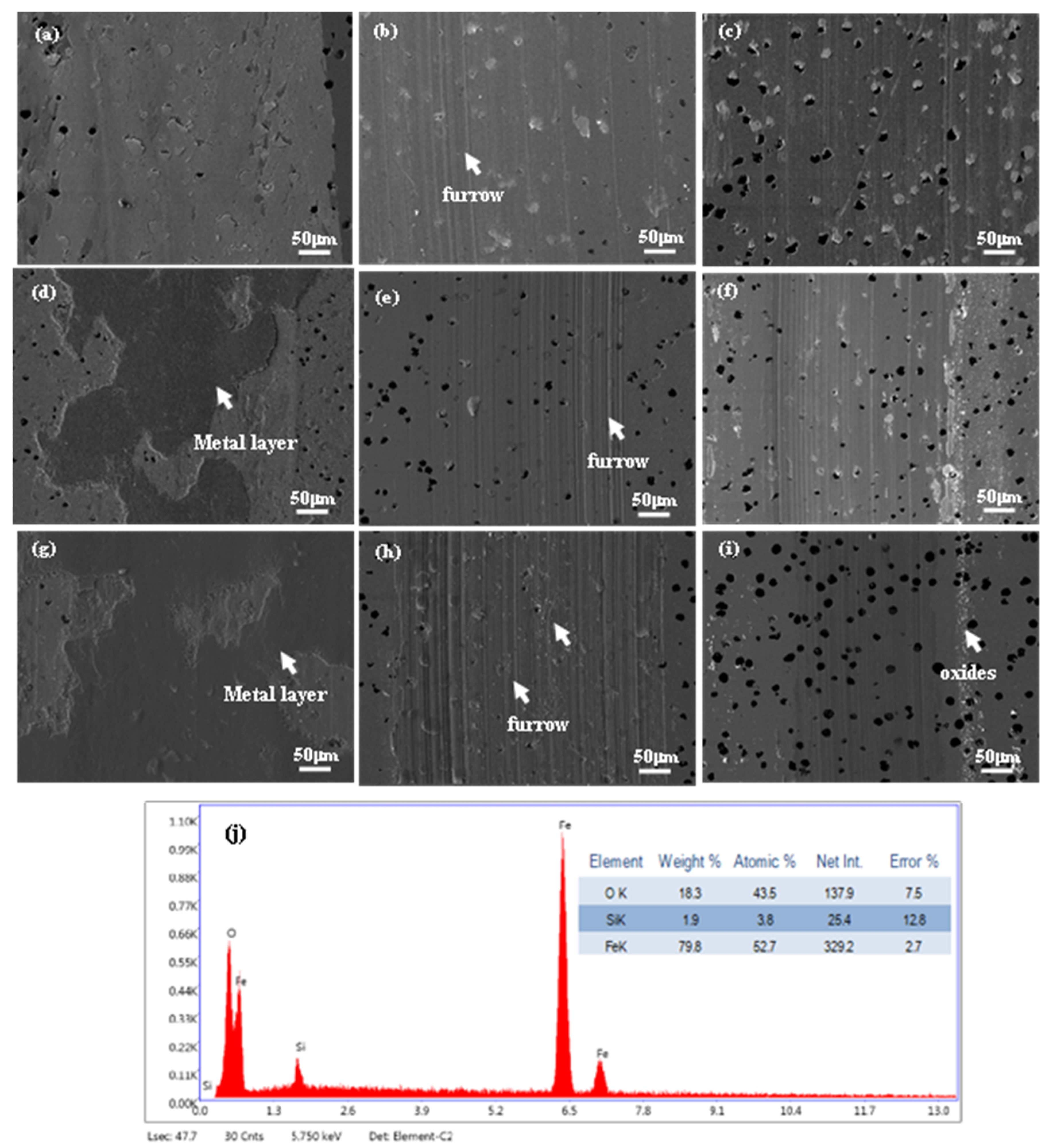
3.2. Tribological Behavior of ADI under Different Wear Conditions

The friction coefficient curves of ADI under various wear conditions are shown in Figure 8. All the friction coefficients of ADI increased first, and then they declined until it reached a steady value. At the initial stage, the frictional resistance generated by the asperities on the tribosurface resulted in the increase in the friction coefficient. The friction coefficient decreased quickly as the asperities gradually flattened and the spherical graphite was transported to the surface, forming a lubricating layer. The worn debris developed on the tribosurface in the subsequent stage as a result of the reciprocating effects of contact stress, creating an uneven surface that encourages the increase in the friction coefficient. Yet, the amount of graphite that was transferred to the tribosurface increased, which helped to lower the friction coefficient. As a result of the interaction between the surface roughness and graphite, the friction coefficient of ADI reached a steady value.
Figure 9 depicts the variation of the friction coefficient at the steady stage with sliding speed. Under a given speed, it can be seen that the friction coefficient dropped as the load increased. The decreasing tendency was not apparent when the sliding speed was slow. The friction coefficient decreased significantly with the normal load applied at high sliding speed. Moreover, the friction coefficient decreased a little at low normal load (5 N) but decreased obviously at high normal load (20 N) with the increase in sliding speed. The friction coefficient reached the lowest value (around 0.1) when the normal load was 20 N and the sliding speed was 500 r/min. During the wear test, the surface roughness and the development of a graphite lubricating layer on the tribosurface were critical factors to determine the friction coefficient under various service conditions. The variation of the friction coefficient will be discussed by combining the microstructure of the worn surface in the following.
Figure 10 presents the wear rate of ADI under various service conditions. It can be seen that the wear rate increased with the increase in the normal load, while it decreased with an increase in sliding speed. According to the Archard equation [18], the wear rate of materials is proportional to the normal load and inversely proportional to the hardness of materials. Hence, increasing the normal load was conducive to the rise in ADI’s wear rate in the present study. Meanwhile, the friction coefficient is another important factor affecting wear resistance [30]. The friction coefficient was reduced with the increase in the normal load and sliding speed (Figure 9). Therefore, the wear rate decreased with the increase in sliding speed under a certain normal load. Moreover, the difference in the wear rate under different normal loads at low sliding speed was more obvious than that at high sliding. This was due to the large reduction in the friction coefficient at sliding speed (Figure 9).

4. Discussion

The tribological behavior of ADI was susceptible to wear conditions based on the results above. As the normal load and sliding speed increased, the friction coefficient decreased. While the wear rate decreased as sliding speed rose, it increased with an increase in the normal load. The following section will describe the specific tribological behavior under various conditions.
The friction coefficient was related to the formation of graphite film in cast iron [31]. High normal load caused plastic deformation of the ADI matrix, which allowed the spheroid graphite to transfer from the matrix to the tribosurface easily, helping to promote the formation of graphite film. Figure 11 shows the optical images of ADI after wear tests. It was evident that the graphite on the surface increased with the increase in normal load. As a result, increasing the normal load sped up the formation of graphite films on the tribosurface, which thereby lowered the friction coefficient. By contrasting the worn surface of ADI, it can be seen that the amounts of graphite on the tribosurface decreased with the increase in sliding speed. When the graphite was transferred to the tribosurface, the graphite rapidly spread on the tribosurface at high sliding speed, which was beneficial for the reduction in the friction coefficient. Moreover, the debris on the tribosurface was more easily oxidized at high sliding speed, which will be mentioned in the following. The oxides always exhibited a low friction coefficient. Consequently, the friction coefficient was decreased with the increase in sliding speed.
The wear mechanism of ADI differed under different service conditions. To further explore the influence of service conditions on the wear mechanism of ADI, the SEM morphology of the worn surface is presented in Figure 12. No obvious furrows were detected for samples at a low rotating rate (100 r/min) (Figure 12a,d,g). For samples at a high rotating rate (300 r/min), obvious furrows were observed (Figure 12b,e,h). Wear debris was detected in addition to furrows (Figure 12c,f,i) when further increasing the sliding speed (500 r/min). Therefore, it could be inferred that the ADI exhibited different wear mechanisms under different service conditions. For the samples at a low rotating rate, the matrix was deformed plastically and then spread on the worn surface with the increase in normal load (Figure 12d,g). This indicated that adhesive wear was predominant at a low sliding speed. With the increase in the sliding speed, a lot of furrows were detected (Figure 12b,e,h) and the amounts of furrows increased with the increase in the normal load. The matrix was more easily plastically deformed under a high normal load, which resulted in more matrix transferred to the tribosurface. In the following dry sliding, the debris acted as abrasive particles and gave rise to the formation of furrows. Further increasing the sliding speed, the wear debris near the wear track was detected (Figure 12f,i), which was confirmed to be iron oxide by EDS analysis (Figure 12j). The temperature at the contact point, which is called flash temperature, increases during dry sliding between the tribosurface. It has been reported that the flash temperature could reach approximately 1000 °C for flake graphite cast iron during wear tests [32]. The flash temperature is hard to measure because of the rapid variation during the test, but it is known that flash temperature increased with the increase in sliding speed because the frictional heat generated during the wear tests was approximate to the sliding speed [32]. Hence, the wear debris produced during wear tests could be oxidized. The oxides could be flattened on the tribosurface, which could avoid the direct contact of the friction pair and then reduce the wear rate [33]. Hence, the wear rate decreased with the increase in sliding speed.

5. Conclusions

In the present study, ductile iron was fabricated by a vertically continuous casting method, and the tribological behavior of ADI under various wear conditions was investigated in the present study. The correlationship between the wear conditions and wear properties was analyzed, and the main conclusions are summarized as follows.
(1)
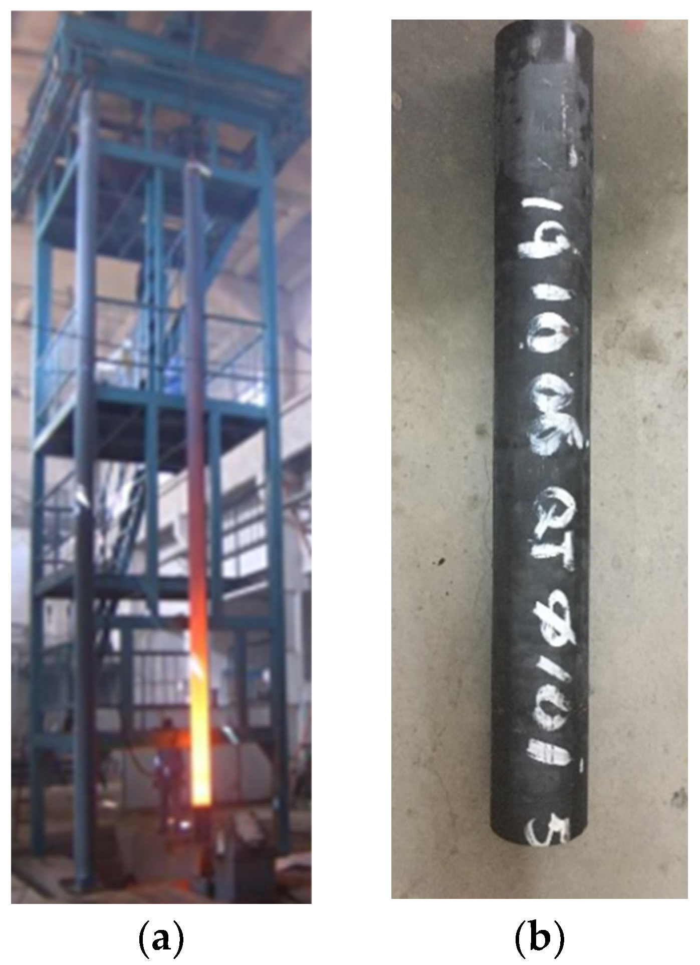
A ductile iron with approximately 300/mm2 of graphite nodule distributing around the matrix was fabricated by a vertically continuous casting method, the matrix of which was composed of ferrite and pearlite.
(2)
Compared with the as-cast ductile iron, ADI exhibited a much higher strength with an ultimate tensile strength of approximately 1220 MPa. This high strength was because the nanoscale microstructure strengthened the alloy by grain boundaries and carbon atoms in α and γ phase strengthened the alloy by solution strengthening.
(3)
The friction coefficient of ADI was affected obviously by the service conditions, in which increasing normal load and sliding speed reduced the friction coefficient. This was mainly related to the amounts of graphite transferred from the matrix to the tribosurface and the formation of the graphite lubricant layer.
(4)
The wear rate of ADI increased with increasing the normal load but decreased with the increase in sliding speed. The temperature on tribosurface increased with the increase in sliding speed, which promoted the oxidation of wear debris and then reduced the wear rate.
(5)
The main wear mechanism of ADI was adhesive wear at low sliding speed, but oxidation wear was predominant under high sliding speed.

Author Contributions

Conceptualization, Y.D.; methodology, Y.D.; validation, Z.H.; formal analysis, Z.H.; investigation, Z.H.; resources, Z.H.; data curation, Z.H.; writing—original draft preparation, Z.H.; writing—review and editing, Y.D.; visualization, Z.H.; supervision, Y.D.; project administration, Y.D.; funding acquisition, Y.D. All authors have read and agreed to the published version of the manuscript.

Funding

This work was supported by the Applied Technology Research Project of Beilin District (No. GX2250).

Data Availability Statement

The data that support this study are available from the corresponding author upon reasonable request.

Conflicts of Interest

The authors declare that they have no known competing financial interests or personal relationships that could have appeared to influence the work reported in this paper.

References

  1. Artola, G.; Gallastegi, I.; Izaga, J.; Barreña, M.; Rimmer, A. Austempered Ductile Iron (ADI) Alternative Material for High-Performance Applications. Int. J. Met. 2017, 11, 131–135. [Google Scholar] [CrossRef]
  2. Pereira, L.; Amaral, R.F.D.; Wolfart, M.; Barcellos, V.K.D. Microstructural and mechanical properties of Cu-Ni-Mn-Mo austempered ductile iron obtained from two-step hot air austempering. J. Mater. Res. Technol. 2020, 9, 3055–3063. [Google Scholar] [CrossRef]
  3. Labrecque, C.; Gagné, M. Ductile iron: Fifty years of continuous development. Can. Metall. Q. 1998, 37, 343–378. [Google Scholar] [CrossRef]
  4. Wang, X.; Du, Y.; Liu, B.; Jiang, B. Enhanced plasticity of austempered ductile iron (ADI) by partitioning treatment. Mater. Sci. Eng. A 2021, 804, 140513. [Google Scholar] [CrossRef]
  5. Sellamuthu, P.; Samuel, D.; Dinakaran, D.; Premkumar, V.; Li, Z.; Seetharaman, S. Austempered Ductile Iron (ADI): Influence of Austempering Temperature on Microstructure. Mechanical and Wear Properties and Energy Consumption. Metals 2018, 8, 53–64. [Google Scholar] [CrossRef]
  6. Wang, X.; Du, Y.; Liu, C.; Hu, Z.; Li, P.; Gao, Z.; Guo, H.; Jiang, B. Relationship among process parameters, microstructure, and mechanical properties of austempered ductile iron (ADI). Mater. Sci. Eng. A 2022, 857, 144063. [Google Scholar] [CrossRef]
  7. Franzen, D.; Pustal, B.; Bührig-Polaczek, A. Mechanical Properties and Impact Toughness of Molybdenum Alloyed Ductile Iron. Int. J. Met. 2021, 15, 983–994. [Google Scholar] [CrossRef]
  8. Uyar, A.; Sahin, O.; Nalcaci, B.; Kilicli, V. Effect of Austempering Times on the Microstructures and Mechanical Properties of Dual-Matrix Structure Austempered Ductile Iron (DMS-ADI). Int. J. Met. 2022, 16, 407–418. [Google Scholar] [CrossRef]
  9. Du, Y.; Wang, X.; Zhang, D.; Wang, X.; Ju, C.; Jiang, B. A superior strength and sliding-wear resistance combination of ductile iron with nanobainitic matrix. J. Mater. Res. Technol. 2021, 11, 1175–1183. [Google Scholar] [CrossRef]
  10. Du, Y.Z.; Gao, X.Q.; Wang, X.L.; Wang, X.; Ge, Y.F.; Jiang, B.L. Tribological behavior of austempered ductile iron (ADI) obtained at different austempering temperatures. Wear 2020, 456, 203396. [Google Scholar] [CrossRef]
  11. Putatunda, S.K. Development of austempered ductile cast iron (ADI) with simultaneous high yield strength and fracture toughness by a novel two-step austempering process. Mater. Sci. Eng. A 2001, 315, 70–80. [Google Scholar] [CrossRef]
  12. Pimentel, A.S.O.; Guesser, W.L.; da Silva, W.J.R.C.; Portella, P.D.; Woydt, M.; Burbank, J. Abrasive wear behavior of austempered ductile iron with niobium additions. Wear 2019, 440-441, 203065. [Google Scholar] [CrossRef]
  13. Hu, Z.; Liu, C.; Du, Y.; Wang, X.; Zhu, X.; Jiang, B. Effects of Tempering Temperature on Mechanical and Tribological Behavior of Ductile Iron. Lubricants 2022, 10, 326. [Google Scholar] [CrossRef]
  14. Takeuchi, E. The mechanisms of wear of cast iron in dry sliding. Wear 1968, 11, 201–212. [Google Scholar] [CrossRef]
  15. Masuda, K.; Oguma, N.; Ishiguro, M.; Sakamoto, Y.; Ishihara, S. Sliding wear life and sliding wear mechanism of gray cast iron AISI NO.35B. Wear 2021, 474–475, 203870. [Google Scholar] [CrossRef]
  16. Yang, Z.-R.; Li, D.-S.; Wang, L.; Wang, S.-Q.; Wei, M.-X. Wear Behavior and Mechanism of Spheroidal Graphite Cast Iron. J. Iron Steel Res. Int. 2013, 20, 81–86. [Google Scholar] [CrossRef]
  17. Zhang, H.; Wu, Y.-X.; Li, Q.-J.; Hong, X. Effect of matrix structure on mechanical properties and dry rolling–sliding wear performance of alloyed ductile iron. J. Iron Steel Res. Int. 2019, 26, 888–897. [Google Scholar] [CrossRef]
  18. Archard, J.F. Contact and Rubbing of Flat Surfaces. J. Appl. Phys. 1953, 24, 981–988. [Google Scholar] [CrossRef]
  19. Mussa, A.; Krakhmalev, P.; Bergström, J. Wear mechanisms and wear resistance of austempered ductile iron in reciprocal sliding contact. Wear 2022, 498–499, 204305. [Google Scholar] [CrossRef]
  20. Rezende, A.B.; Fonseca, S.T.; Miranda, R.S.; Fernandes, F.M.; Grijalba, F.A.F.; Farina, P.F.S.; Mei, P.R. Effect of niobium and molybdenum addition on the wear resistance and the rolling contact fatigue of railway wheels. Wear 2021, 466–467, 203571. [Google Scholar] [CrossRef]
  21. Liu, C.; Du, Y.; Wang, X.; Zheng, Q.; Zhu, X.; Zhang, D.; Liu, D.; Yang, C.; Jiang, B. Comparison of the tribological behavior of quench-tempered ductile iron and austempered ductile iron with similar hardness. Wear 2023, 520–521, 204668. [Google Scholar] [CrossRef]
  22. Laino, S.; Sikora, J.A.; Dommarco, R.C. Development of wear resistant carbidic austempered ductile iron (CADI). Wear 2008, 265, 1–7. [Google Scholar] [CrossRef]
  23. Zimba, J.; Samandi, M.; Yu, D.; Chandra, T.; Navara, E.; Simbi, D.J. Un-lubricated sliding wear performance of unalloyed austempered ductile iron under high contact stresses. Mater. Des. 2004, 25, 431–438. [Google Scholar] [CrossRef]
  24. Yan, G.; Xu, Y.; Jiang, B. The production of high-density hollow cast-iron bars by vertically continuous casting. J. Mater. Process. Technol. 2012, 212, 15–18. [Google Scholar] [CrossRef]
  25. Sourmail, T.; Caballero, F.G.; Moudian, F.; De Castro, D.; Benito, M. High hardness and retained austenite stability in Si-bearing hypereutectoid steel through new heat treatment design principles. Mater. Des. 2018, 142, 279–287. [Google Scholar] [CrossRef]
  26. Kim, K.-W.; Kim, K., II; Lee, C.-H.; Kang, J.-Y.; Lee, T.-H.; Cho, K.-M.; Oh, K.H. Control of retained austenite morphology through double bainitic transformation. Mater. Sci. Eng. A 2016, 673, 557–561. [Google Scholar] [CrossRef]
  27. He, T.; Wang, L.; Hu, F.; Zhou, W.; Zhang, Z.; Wu, K. Stability of retained austenite and work hardening behavior in ultra-fine medium carbon bainitic steel. J. Mater. Res. Technol. 2023, 22, 2690–2703. [Google Scholar] [CrossRef]
  28. Pereira, H.B.; Tschiptschin, A.P.; Goldenstein, H.; Azevedo, C.R.F. Effect of the Austenitization Route on the Bainitic Reaction Kinetics and Tensile Properties of an Alloyed Austempered Ductile Iron. Int. J. Met. 2021, 15, 1442–1455. [Google Scholar] [CrossRef]
  29. Caballero, F.G.; Miller, M.K.; Garcia-Mateo, C. Carbon supersaturation of ferrite in a nanocrystalline bainitic steel. Acta Mater. 2010, 58, 2338–2343. [Google Scholar] [CrossRef]
  30. Sugishita, J.; Fujiyoshi, S. The effect of cast iron graphites on friction and wear performance: II: Variables influencing graphite film formation. Wear 1981, 68, 7–20. [Google Scholar] [CrossRef]
  31. Sugishita, J.; Fujiyoshi, S. The effect of cast iron graphites on friction and wear performance I: Graphite film formation on grey cast iron surfaces. Wear 1981, 66, 209–221. [Google Scholar] [CrossRef]
  32. Kawamoto, M.; Okabayashi, K. Study of dry sliding wear of cast iron as a function of surface temperature. Wear 1980, 58, 59–95. [Google Scholar] [CrossRef]
  33. Wei, M.X.; Chen, K.M.; Wang, S.Q.; Cui, X.H. Analysis for Wear Behaviors of Oxidative Wear. Tribol. Lett. 2011, 42, 1–7. [Google Scholar] [CrossRef]
Figure 1. The schematic diagram of the fabrication of ductile iron pipe. A—drawing machine, B—hollow ductile iron casting, C—crystallizer, D—water entry, E—water outlet, F—iron melt, G—continuous casting furnace, H—container, I—heater, J—pouring gate, and K—cooling system.
Lubricants 11 00182 g001
Figure 2. (a) The fabrication procedure and (b) hollow ductile iron casting.
Lubricants 11 00182 g002
Figure 3. (a) Schematic diagram of pin-on-disc tribotester, and (b) the used tribotester.
Lubricants 11 00182 g003
Figure 4. Optical images of as-cast ductile iron (a) unetched and (b) etched.
Lubricants 11 00182 g004
Figure 5. (a) Optical and (b) SEM images of ADI sample.
Lubricants 11 00182 g005
Figure 6. XRD patterns of ADI sample.
Lubricants 11 00182 g006
Figure 7. The typical stress–strain curves for the ductile iron.
Lubricants 11 00182 g007
Figure 8. Variation of friction coefficient of ADI during wear tests: (a) 100 r/min, (b) 300 r/min, and (c) 500 r/min.
Lubricants 11 00182 g008
Figure 9. Friction coefficient at steady stage of ADI.
Lubricants 11 00182 g009
Figure 10. Variation of wear rate of ADI with sliding speed.
Lubricants 11 00182 g010
Figure 11. Optical images of the worn surface under different wear conditions: (a) 5N and 100 r/min, (b) 5N and 300 r/min, (c) 5N and 500 r/min, (d) 10N and 100 r/min, (e) 10 N and 300 r/min, (f) 10N and 500 r/min, (g) 20N and 100 r/min, (h) 20 N and 300 r/min, and (i) 20 N and 500 r/min.
Lubricants 11 00182 g011
Figure 12. Optical images of the worn surface under different wear conditions: (a) 5N and 100 r/min, (b) 5N and 300 r/min, (c) 5N and 500 r/min, (d) 10N and 100 r/min, (e) 10 N and 300 r/min, (f) 10N and 500 r/min, (g) 20N and 100 r/min, (h) 20 N and 300 r/min, and (i) 20 N and 500 r/min, (j) EDS results of the oxides in (i).
Lubricants 11 00182 g012
Table 1. The chemical composition of the ductile iron in the present study.
ElementCSiMnSPMgCeFe
Weight Fraction wt.%3.622.560.200.0120.0320.0400.035Balance
Disclaimer/Publisher’s Note: The statements, opinions and data contained in all publications are solely those of the individual author(s) and contributor(s) and not of MDPI and/or the editor(s). MDPI and/or the editor(s) disclaim responsibility for any injury to people or property resulting from any ideas, methods, instructions or products referred to in the content.

