Article

Erosive Wear Behavior of Novel Hybrid Multicomponent Cast Alloys with Different C and B Contents

1
Graduate School of Engineering, Muroran Institute of Technology, 27-1 Mizumoto, Muroran City 050-8585, Japan
2
Department of Mechanical Engineering, University of Sumatera Utara, Medan 20155, Indonesia
3
College of Design & Manufacturing Technology, Muroran Institute of Technology, Muroran 050-8585, Japan
4
Physics Department, Pryazovskyi State Technical University, 87555 Mariupol, Ukraine
*
Author to whom correspondence should be addressed.
Lubricants 2023, 11(6), 243; https://doi.org/10.3390/lubricants11060243
Submission received: 9 May 2023 / Revised: 24 May 2023 / Accepted: 29 May 2023 / Published: 31 May 2023
(This article belongs to the Special Issue Frictional Behavior and Wear Performance of Cast Irons)

Abstract

:
Multicomponent and high-boron cast alloys have been recognized as materials with excellent wear resistance due to the formation of hard phases called carbides and borides. However, the wear performance of the combination of these two materials called hybrid multicomponent cast alloys (HMCAs) has not been comprehensively studied. Therefore, this study will evaluate the effect of C (0–0.9 wt.%) and B (1.5–3.5 wt.%) addition on the erosion wear behavior of an HMCA containing 2.5 wt.% Ti, 10 wt.% Cr, and 5 wt.% each of V, Mo, and W. Shot-blast erosion testing was used to evaluate the wear resistance of each alloy. The test was conducted for 3600 s using 2 kg of irregularly shaped steel sand as a scraper at impact angles of 30°, 60°, and 90°. The results showed that the highest wear rate in 0C and 0.45C with 1.5–3.5% B occurred at an impact angle of 60° due to gouging and indentation mechanisms occurring simultaneously. However, different results occurred in the case of 0.9C with the same amount of B where the wear rate increased with increasing impact angle due to brittleness. Based on the chemical composition, the wear resistance of the alloy increased with increasing C content due to higher hardness values. However, the reverse performance occurred when the addition of B exceeded the threshold (more than 1.5 wt.%) despite the higher hardness. This fact was due to the susceptibility to carbide cracking as the amount of B increased. Therefore, the alloy with the best erosion wear resistance was 0.9C–1.5B HMCA.

1. Introduction

Research on wear has received extensive attention from many researchers after the Josh report was released regarding the potential benefits of using materials with excellent wear resistance. Specifically, it has been estimated that the gross national product (GNP) of Japan can be reduced by about 2.6%, Germany by 0.5%, the United States by 0.84%, and China by about 7% [1]. There are several types of wear, one of which is erosive wear. Erosive wear is the loss of material from the surface of a solid material due to the collision of small hard particles trapped by the flow of gas or liquid [2,3]. Erosive wear has been widely discussed by experts, and studies show that various test parameters such as impact angle, particle impact velocity, and temperature are important to consider in investigating erosive wear [4,5,6]. It also depends on the nature of the erodent particles (composition, shape, and hardness) [7,8,9,10]. In addition, the wear behavior of a material is also known to be strongly influenced by the wear properties of the material itself (hardness, carbides, and toughness) [11,12,13]. However, investigations still have to be carried out into how different chemical compositions of the material undergoing wear often give different findings. In addition, erosive wear occurs on many machine parts, e.g., pipes, pump impellers, boiler tubes, rocket nozzles, and turbine blades. It can account for about 8% of mechanical failures due to wear problems [1]. Therefore, in addition to enriching the knowledge of erosive wear, it is very important to conduct research on the development of wear resistance of materials to reduce economic losses during the manufacturing process in industry.
It is well known that the family of cast alloys, such as steel-alloys and white cast iron, commonly exhibit an severe wear phenomenon, especially erosion, owing to their outstanding wear-resistance properties. In recent decades, multicomponent cast iron (MCCI) has been proposed as a suitable wear-resistance material by Matsubara et al. [14] and Shimizu et al. [15,16]. Both of these research groups agree that the outstanding wear resistance of MCCI compared to other cast alloys is due to the formation of several types of hard eutectic carbides (MC, M2C, and M7C3) during the solidification process. The letter M represents the added transition metal. In addition, it is also recommended to carry out a destabilizing heat treatment process to enable the precipitation of secondary carbides and the transformation of the austenite matrix to martensite. However, it is also noted that the C content should be in the hypoeutectic range (less than 3 wt.%) to avoid the tendency of cracking due to simultaneous precipitation of MC, M2C, and M7C3 carbides. In our recent study, the effect of C content in hypoeutectic MCCI was evaluated. It was concluded that the wear resistance of both MCCIs (5V–5Cr–5Mo–5W and 5Nb–5Cr–5Mo–5W) increases as the amount of C (1; 1.5; 2 wt.%) increases [17].
In addition to the development of MCCI, the effect of adding B to cast alloys (Fe-B) has also been investigated separately by previous researchers. At first, B was added in very small percentages to improve the mechanical properties of carbon steel alloys [18,19]. However, it has been found that the wear resistance of these alloys can be improved by more than 0.05 wt.% after the addition of B due to the precipitation of Fe2B boride [20,21]. On the other hand, since the boride has a very high hardness (FeB: 1800–2000 HV and Fe2B: 1400–1600 HV), the amount of C should be reduced (less than 1 wt.%) to avoid cracking tendency [17]. Therefore, Lakeland [22] produced Fe-B alloys with 1.2–3.5 wt.% B and 0.2–0.5 wt.% C. The results show that the microstructure of the alloy containing FeB boride and Fe2(B,C) carbide provides better wear resistance compared with the first generation Fe-B alloy. Continuing this research, the effect of Cr addition on the mechanical properties of these alloys has also been investigated. The results show that the element Cr (8–10 wt.%) can decrease the tendency of carboride cracking of Fe-Cr-B alloy due to the promotion of a ductile bainitic matrix [23,24,25,26]. The addition of Ti element (≈2 wt.%) in the cast alloys has also been comprehensively studied. It is known that the Ti element will first react with the adjacent C to form TiC, leaving less available C in the molten iron during the solidification process of Fe-Cr-C alloys. Thus, the smaller M7C3 carbide will precipitate when the molten iron reaches the appropriate temperature for carbide formation. The refinement of M7C3 carbide provides a higher toughness leading in better wear resistance. In particular, Liu et al. [27] investigated the effect of Ti element on microstructure and mechanical properties of Fe-B alloys. They found that the presence of this element effectively retarded the precipitation of interconnected borides, resulting in better mechanical properties.
Based on the above two cast alloys (MCCI and Fe–Cr–B–C), Efremenko and his colleagues [28,29] tried to combine these two material design concepts, to form a hybrid multicomponent cast alloy (HMCA). The microstructure of this new alloy has been comprehensively discussed in the above articles. It was found that this alloy consists of several types of eutectics named “Chinese-script” and rosetted and M2(B,C)5, M(C,B), M7(C,B)3, and M3(C,B) carborides. In addition, the matrix of this alloy is ferrite without any signs of autenite matrix. However, the previous studies only focused on characterizing the microstructure of the alloy. Meanwhile, it is important to investigate the wear performance of these new cast alloys as the main goal of material development. Indeed, the wear behavior of HMCAs in as-cast condition under abrasion test has been initiated in the recent research of Chabak et al. [30]. It has been revealed that the increment of eutectic carborides provides better wear performance. However, the wear behavior of this new HMCA under erosive wear conditions has not been investigated. In addition, although improvements have been obtained, it is still possible to suppress the cracking tendency by lowering the amount of C to less than 1.1 wt.% without inhibiting the formation of borides or carborides. To address this research gap, the effect of C (0–0.9 wt.%) and B (1.5–3.5 wt.%) on the erosion wear characteristics of HMCA was evaluated. This reduced C content is expected to be an appropriate solution to reducing economic losses due to wear phenomena occurring on various machine parts such as pipes, pump impellers, boiler tubes, rocket nozzles, and turbine blades.

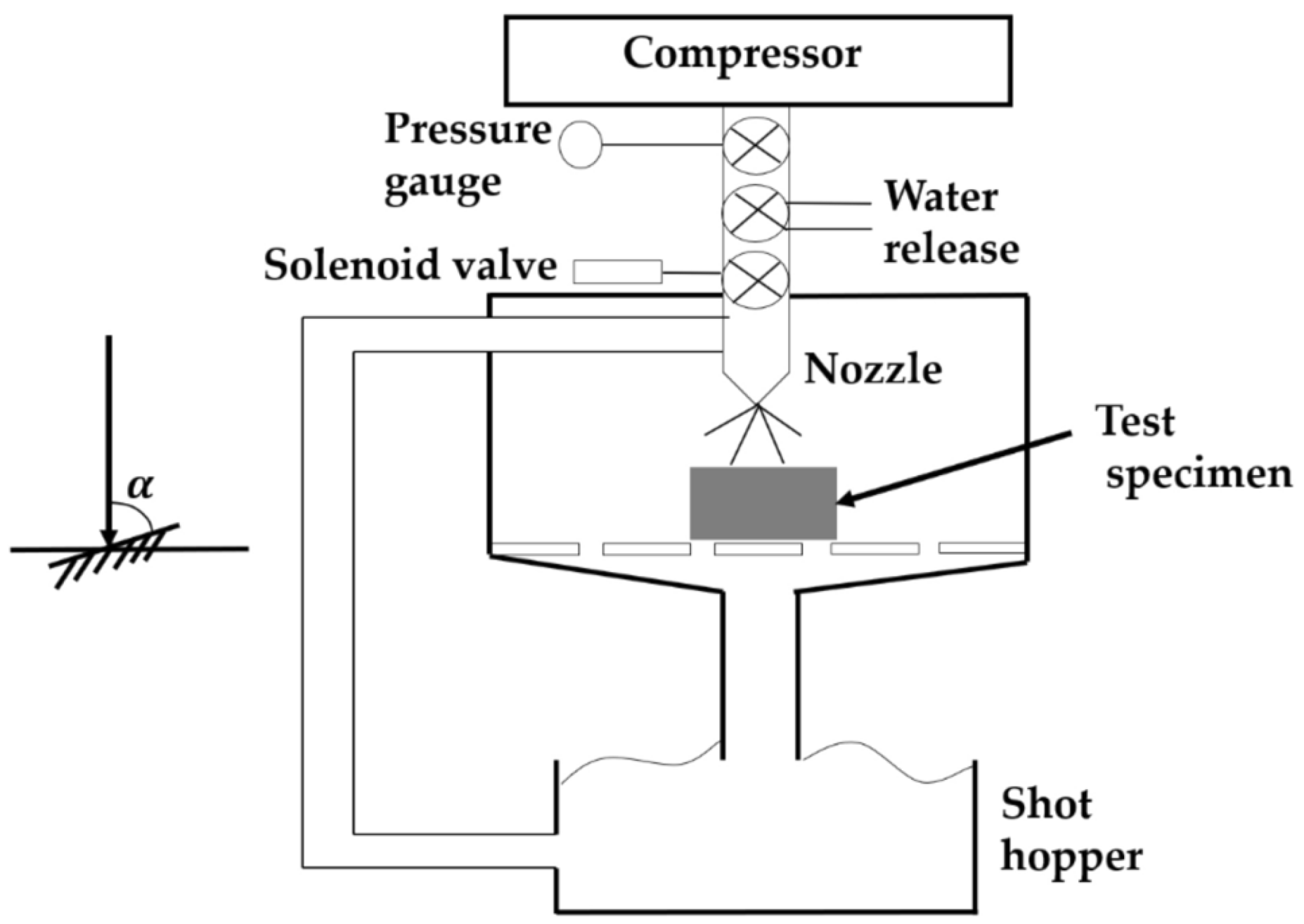
2. Materials and Methods

The alloy studied was designed into one multicomponent cast alloy containing 2.5 wt.% Ti, 10 wt.% Cr, and 5 wt.% Mo, W, and V with three different additions of C (0, 0.45, and 0.9 wt.%) and B (1.5, 2.5, and 3.5 wt.%). In all, nine HMCAs were studied in this research. The manufacturing processes was introduced in our previous research [13]. Approximately 50 kg of each of the added elements was melted in a high-frequency induction furnace and then the molten iron was poured into a Y sand mold. The bottom part of the ingot was cut using a high-speed precision cutting machine (Refinetech Co., Ltd., RCA-234, Kanagawa, Japan) to a size of 50 mm × 50 mm × 10 mm. SPECTROLAB (AMATEK, Inc., Berwyn, PA, USA) was used to measure the chemical composition of each alloy after the manufacturing process. The chemical compositions are provided in Table 1.
In our previous research [31], it was revealed that the quenched category of multicomponent cast alloys had better erosive wear resistance compared to as-cast and quenched-tempered alloys due to higher hardness. The temperature range of the quenching process is usually 1173–1323 K, to harden the matrix and form secondary carbides. Therefore, the cast alloy in this study was also quenched after being heated at 1223 K for 2 h and cooled by air-forced cooling using a fan. The cooling rate for all alloys during the quenching process was the same (approximately 2.5 K/s) to ensure all cast alloys were subjected to the same treatment.
Small cubic specimens (10 mm × 10 mm × 10 mm) were fabricated to observe the microstructure of each alloy. Prior to analysis, the specimens were gently polished with 1200 P fine silica sand, followed by 9, 3, and, finally, 0.03 μm diamond suspension paste to avoid cracking of the borides/carborides. These were analyzed using optical microscopy (OM; Eclipse LV150N, Nikon, Tokyo, Japan) and scanning electron microscopy (SEM + EDS; JSM-6510A, JEOL, Tokyo, Japan). In addition, the bulk areas (Chinese-script eutectics, rosette eutectics, borides, and carborides) were calculated using the binarization technique using 5 SEM images. First, 5 SEM images with 400× magnification were stained using paint application to increase the contrast of the bulk area and matrix. Then, the images were uploaded to ImageJ to calculate the total bulk area. In this study, the result was assumed to be the bulk volume fraction. Spot analysis was performed at more than 15 random locations on the SEM microphotos to determine the type of boride/carboride. In addition, the hardness of each alloy was also investigated. There are two types of Vickers hardness data, the microhardness is assumed to be matrix hardness only, and the macrohardness is matrix and bulk. Microhardness was measured using a Future-Tech Co: FM-300, Kanagawa, Japan, while the macrohardness was measured using a Future-Tech Co: FV-800, Kanagawa, Japan. The loads of microhardness and macrohardness were 0.25 N and 294 N, respectively. The dwell time of both hardness measurements was 15 s according to the standard Vickers hardness tester used. The measurements were taken for 14 repetitions of the test. However, the highest and lowest values were ignored to minimize data errors. Therefore, the average hardness of 12 measurements was used in this study.
A shot-blast erosive wear machine test was used to determine the wear behavior of each HMCA. The machine testing scheme is given in Figure 1. The test was conducted for 3600 s and repeated six times. The average of each data obtained was used and 2 kg of irregularly shaped steel grit was used as the erodent particle. The hardness and size of erodent were 810 HV and 770 μm, respectively. During the test, the erodent was injected at 200 m/s and 0.49 MPa at three different impact angles (30°, 60°, and 90°). The weight of the HMCA before and after the test was measured using an electronic balance (GH-300 A&D Co., Ltd, Tokyo, Japan). The erosive wear rate was calculated using Equation (1). In addition, the wear mechanism of the HMCA was also evaluated through the worn surface and cross section after the erosive wear test.
Erosion   rate   = Mass   removal   per   sec ond   ( g s ) × Density   ( g cm 3 ) Mass   of   impact   particle   per   sec ond   ( g s )

3. Results and Discussions

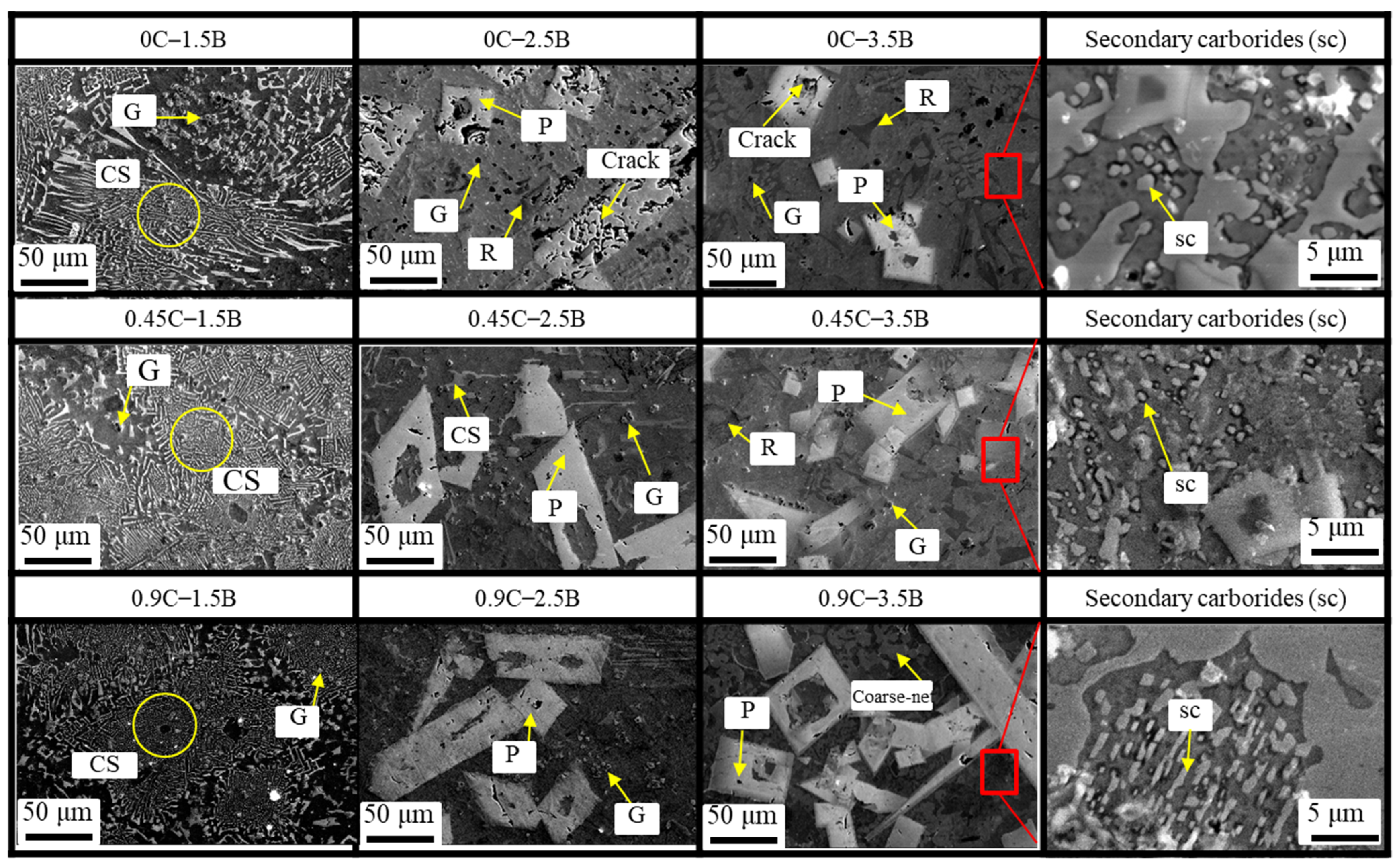
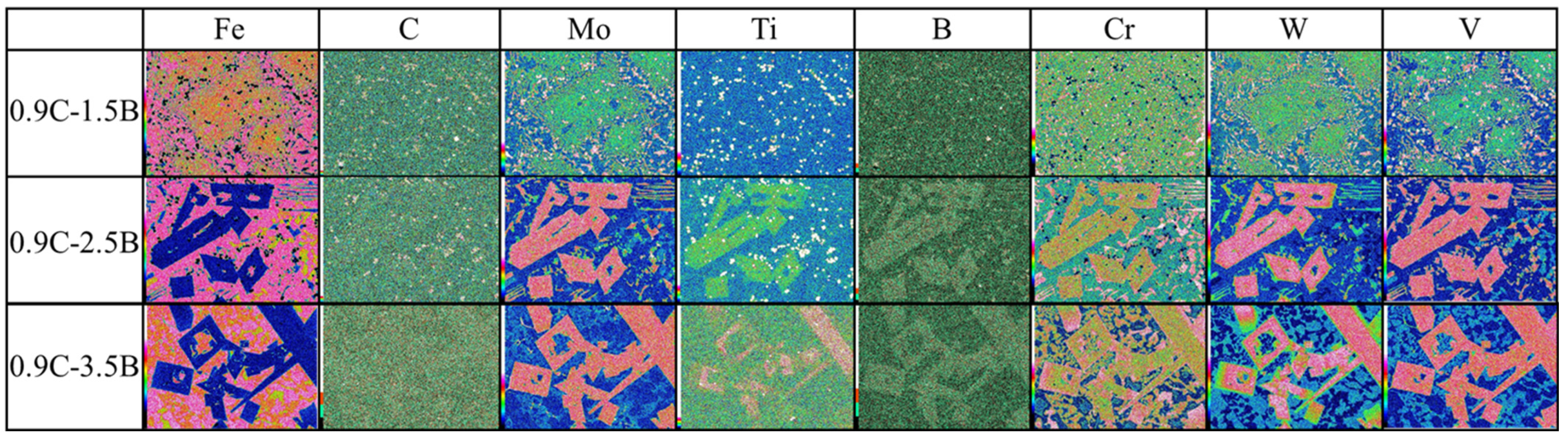
3.1. Microstructure Observation

In general, microstructure greatly affects the wear behavior of cast alloy. Therefore, this was also examined in this study. The microstructure of each alloy is shown in Figure 2 obtained by SEM-EDS. It can be seen that the microstructure of 0C–1.5B consists mainly of eutectic phases and ferrite matrix without primary (P) boride or austenite matrix. Most of the eutectic phase is solidified in the form of colonies that have a fiber-like shape. These eutectics appear similar to previous findings in the microstructure of Al-Mg-Si alloys named “Chinese-Script (CS)” [32,33]. Therefore, the term CS will also be used in this study. In addition, globular eutectics (G) can also be found scattered along the matrix. From the EDS, as shown in Figure 3, the G phase is mostly occupied by elemental Ti that can be assumed as MB borride (the letter M represents Ti). The size of G (≈5 μm) does not differ significantly as the amount of C or B increases. The same condition of microstructure can also be observed in 0.45C and 0.9C alloys with the same amount of B addition.
As the amount of B increased to 2.5 wt.%, the primary (P) carborides were embedded within the microstructure at either 0C, 0.45C, or 0.9C alloy. This hard phase is as M2(C,B)5 carborides which is in good agreement to previous study [28]. It has rectangular shape that appears similar with increasing amounts of C. The size is also similar, with an average of ≈125 μm. It seems to crack easily which might be due to its brittleness. However, the cracks progressively disappear as the amount of C increases. Just like alloy 1.5B, the presence of G can be observed where Ti mostly occupies this phase, as shown in Figure 3. After the C element was added at 0.45 and 0.9 wt.%, it also embedded G boride. This means that MB boride transformed into M(C,B) carboride [28]. In addition, the CS eutectic cannot be observed in the microstructure of the 0C–2.5B alloy—it transforms into a “rosette-like (R)” eutectic [28]. However, the appearance of CS eutectic still exists in the microstructure of 0.45C–2.5B and 0.9C–3.5B alloys, and no R eutectic is observed.
In the case of 0C–3.5B alloy, the presence of M2(C,B)5 as the P carboride, M(C,B) carboride (G), and R eutectic in the ferrite matrix can be encountered [28]. Cracks appear on the P carborides, as shown in the figure. The number of P carborides seems to increase as the C increases. This is because during solidification, the composition of the melt will be less at the liquidus temperature and will increase at the final or near-solid stage. The tip of the solid dendrite also has a lower concentration at the liquidus stage and increases as solidification continues. These two changes in concentration from the initial concentration (C0) to the final stage are referred to as micro-segregation. Micro-segregation is strongly influenced by the equilibrium partition coefficient which is the ratio of liquid composition to solid composition (CL/CS). The Cl and CS depend on the constant partition coefficient (k). Unfortunately, the value of k in the case of multicomponent cast alloys is very difficult to solve due to the simultaneous complex interaction of the added multi elements. However, it is believed that once micro-segregation occurs in molten iron, it will increase the inclusion fraction. The added elements C and B and transition metals have the properties to increase the probability of micro-segregation. Therefore, a higher amount of C will increase the tendency of micro-segregation resulting in more P carbides in the microstructure of the alloy studied in the present investigation. However, to provide accurate data, the effect of B and C addition to the bulk volume fraction was also calculated. This will be discussed further in Section 3.2. In Figure 2, the presence of R eutectic can be seen in the microstructure of 0C–3.5B alloy. However, the existence of CS eutectic cannot be found. In addition, it is difficult to find cracking in P carborides of 0.45C–3.5B and 0.9C–3.5B alloys. Thus, it can be said that the C element effectively strengthens the P carboride. The presence of M(C,B) carborides seems to be less in the 0.45C–3.5B alloys and it cannot even be found in the microstructure of the 0.9C–3.5B alloy. This might be due to the simultaneous embedding of Ti in the M2(C,B)5 carborides, as shown in the elemental distribution of Figure 3. In addition, the CS eutectic cannot be found in the microstructure of 0.45C–3.5B. In the case of 0.9C–3.5B, neither SC nor R eutectic can be found, instead coarse-nets are formed in the microstructure and it is mostly occupied by elemental Cr. The morphology of this coarse-net looks like M7C3 carbide in Fe-Cr-C alloys. Therefore, it can be assumed as M7(C,B)3 carborides, as described in the earlier published paper [28]. In addition, it can be seen that the elements W, Mo, and V are mostly embedded in the area of M2(C,B)5, M(C,B), and M7(C,B)3 carboborides. This is due to the high affinity of these transition metals to C and B. Meanwhile, elemental Fe is mainly solidified as the matrix. By lowering the magnification of SEM microphotograph, it can be seen that there are fine secondary carborides embedded in long areas of the matrix area. These must be precipitated during the heat-treatment process. However, there were no significant differences observed in either the shape, number, or size (≈0.5–2 μm) of the secondary carborides of each alloy. Since there is no appreciable difference in secondary carborides between the alloys, their influence on the erosive wear behavior of the alloys is negligible.
By doing deep etching with nital for about 12 h, all eutectics (CS, R, and M(C,B), and M2(C,B)5 and M7(C,B)3 carborides) can be observed in 3D version, as shown in Figure 4. All the eutectic phases of the alloys are connected to each other. In addition, the P carboride appears rod-like and this does not alter significantly as the amount of B increases. From all the findings, it can be said that the eutectics types are highly dependent on the overall chemical composition of the alloy. However, the shape of the carborides is not affected by the addition of C or B.

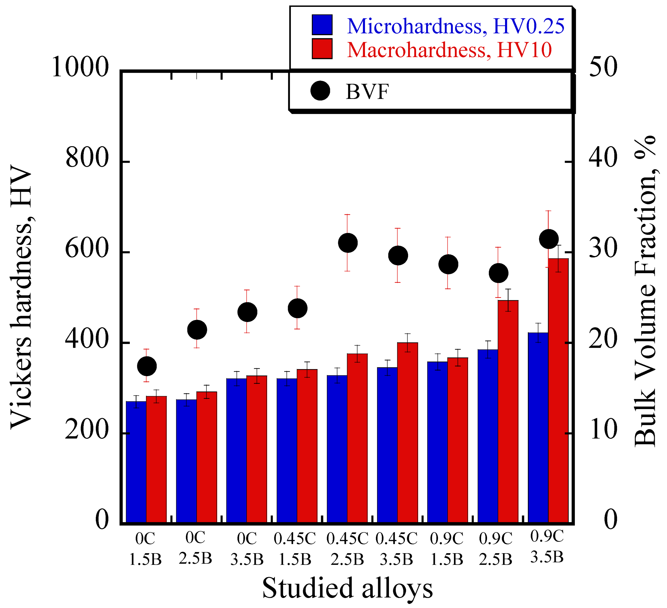
3.2. Bulk Volume Fraction and Hardness of Alloy

Figure 5 is the relationship between total bulk volume fraction (BVF) and Vickers hardness of each alloy. Increasing the BVF in the microstructure of the cast alloy results in a harder material. Thus, the 0.9C–3.5B has the highest hardness (about 586 HV10) owing to having the most BVF (approximately about 31.5%). Meanwhile, the lowest hardness was found in 0C–1.5B (about 282 HV10) due to it having the lowest BVF (approximately 17.5%). In the case of the 0C alloy, the BVF increased as the amount of B increased, resulting in higher hardness values. In the case of 0.45C, the BVF first increased and then slightly decreased as the amount of B increased. On the other hand, the hardness of the alloy was improved which is different from the previous results [12,13,34]. In general, the hardness of the cast alloy will naturally increase as the volume fraction of the hard phase increases. Since eutectic CS does not exist at 0.45C–3.5B, as earlier described, this might be a factor in the reduction of BVF in this study, or, in other words, it can be said that the increase in hardness is not necessarily caused by the increase in BVF. Meanwhile, it is also related to the type of hard phase. However, the reason for the increase in hardness is due to the increase in the amount of M2(C,B)5 as P carboride. In the case of 0.9C, it shows different results. The BVF first decreased and then increased slightly. Neither CS nor R eutectic was formed as the amount of B increased (from 1.5 wt.% to 2.5 wt.%) resulting in a reduction of BVF. However, after the addition of B up to 3.5 wt.%, coarse-net started to form which increased the BVF. On the other hand, the change in BVF did not affect the hardness, as the hardness of the alloy continued to increase as the amount of B increased.
When comparing BVF and hardness with the same amount of B addition, the hardness of 1.5B and 3.5B was consistent with BVF. The higher hardness belonged to the alloys with more BVF due to more C addition. However, a different condition occurred in the case of 2.5B where the BVF first increased, then decreased. On the other hand, the hardness of this alloy improved with increase in the amount of C. The lower BVF of 0.9C compared to 0.45C might have been due to the disappearance of CS or R eutectic in the alloy’s microstructure. Therefore, it can be stated that the elements C or B not only significantly affect the type of hard phase (eutectic and boride/carboride), but also greatly affect the BVF. Meanwhile, the hardness of the alloy was not directly dependent on the change in BVF. Rather, it is affected by the amount of C or B added with more C or B producing greater hardness.

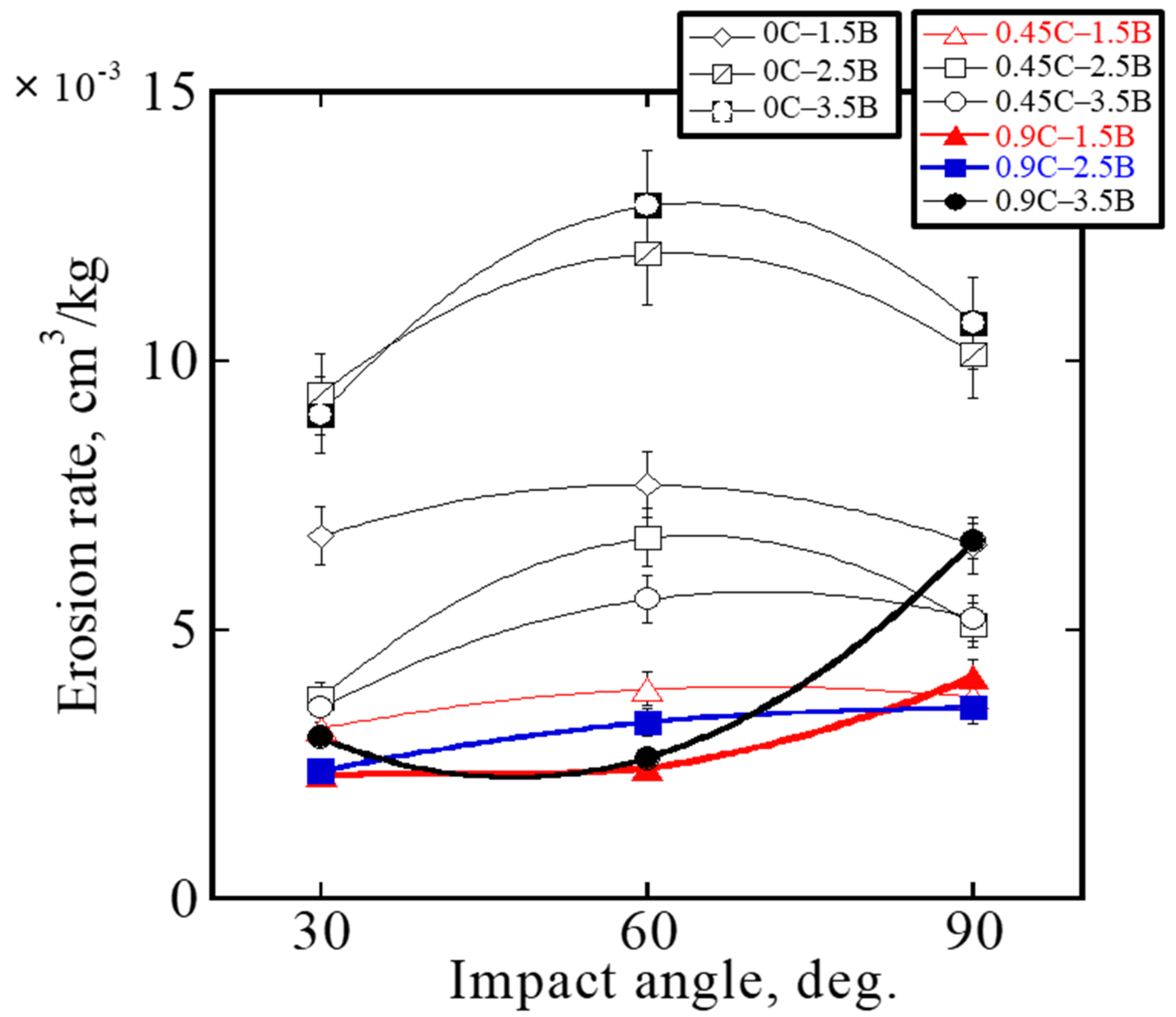
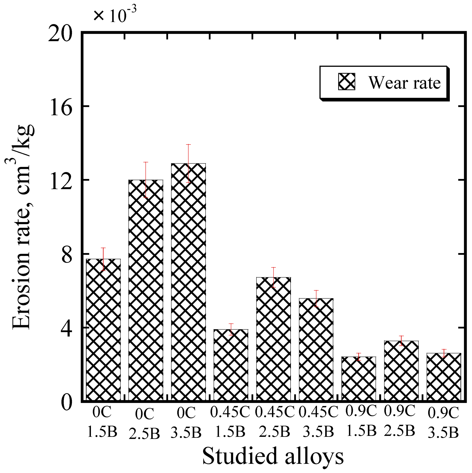
3.3. Erosive Wear Behavior of Each Cast Alloy

In the past, the erosive wear behavior of two types of material based on the impact angle (30°, 60°, and 90°) has been studied. It is known that ductile cast alloys such as steel alloy will easily erode at an impact angle of 30° due to the micro-cutting phenomena. In the case of brittle material such as ceramics, a higher erosion wear rate occurs at an impact angle of 90° due to micro-gouging [35]. However, the effect of impact angle on the wear rate of HMCAs has not yet been reported. Thus, it was systematically evaluated at impact angles of 30°, 60°, and 90° in this study. The results are given in the Figure 6. A different condition was found where 0C with 1.5, 2.5, and 3.5 wt.% B addition experienced the highest erosion wear rate at 60° impact angle. The same tendency also occurred in the case of 0.45C cast alloys which was different from the previous study [35]. However, in the case of 0.9C, the material loss increased as the impact angle increased with the highest erosion wear rate occurring at an impact angle of 90°. It seems that the behavior of ceramic materials is different from that of HMCAs, which might be due to the different erosive wear mechanisms which will be explained in the next section. However, since most cast alloys experienced the highest material loss at 60°, the investigation was focused on this impact angle for a clearer explanation. The results are illustrated in the bar chart, as shown in Figure 7, using the average values from six repetitions of the test. Overall, the best erosion wear resistance was for 0.9C–1.5B (wear rate approx. 2.42 × 10⁻³ cm3/kg) and the worst was for 0C–3.5B cast alloy (wear rate approx. 12.90 × 10⁻³ cm3/kg).
In the case of 0C, it can be seen that the erosion wear rate of the cast alloy increased significantly as the amount of B increased. In many published articles [5,11,13,31], it is reported that higher material hardness will provide better wear resistance. However, although the hardness of 0C increased as the amount of B increased, the formation of primary (P) carboride in the microstructure of 2.5B and 3.5B alloys (which easily cracked) makes these cast alloys too brittle. As a result, the erosive wear resistance dropped significantly, which could be said to be one of the novelties of this study. In the case of 0.45C, the wear rate of the cast alloy first increased, then decreased slightly as B increased from 0 wt.% to 3.5 wt.%. The lower erosion wear resistance of 2.5B and 3.5B compared to 1.5B might be also due to the formation of P carboride. However, the absence of CS eutectic in the microstructure of 3.5B, as described in the previous section, might be a factor of slightly better wear resistance than 2.5B. The same tendency also occurred in the case of 0.9C. The wear resistance of 1.5B was better than others which might be due to the greater resistance to cracking. In addition, the wear resistance of 3.5B was slightly better than 2.5B which might be related to the formation of coarse-net.
When comparing cast alloys with the same amount of B addition, the wear resistance of the cast alloys increased significantly as the amount of C increased from 0 to 0.9 wt.%. The improvement might be associated to the increment of material‘s hardness. It means that the erosive wear behavior of the present cast alloy is influenced by the microstructure as well as the hardness. In other words, the higher hardness provides better wear resistance. However, the opposite performance will occur when the microstructure consists of P carboride. Therefore, it is important to control the microstructure constituent and the appropriate hardness to achieve an excellent wear-resistance material. To better understand the erosive wear behavior of hybrid multicomponent cast alloys, the wear mechanism will be discussed in the section.

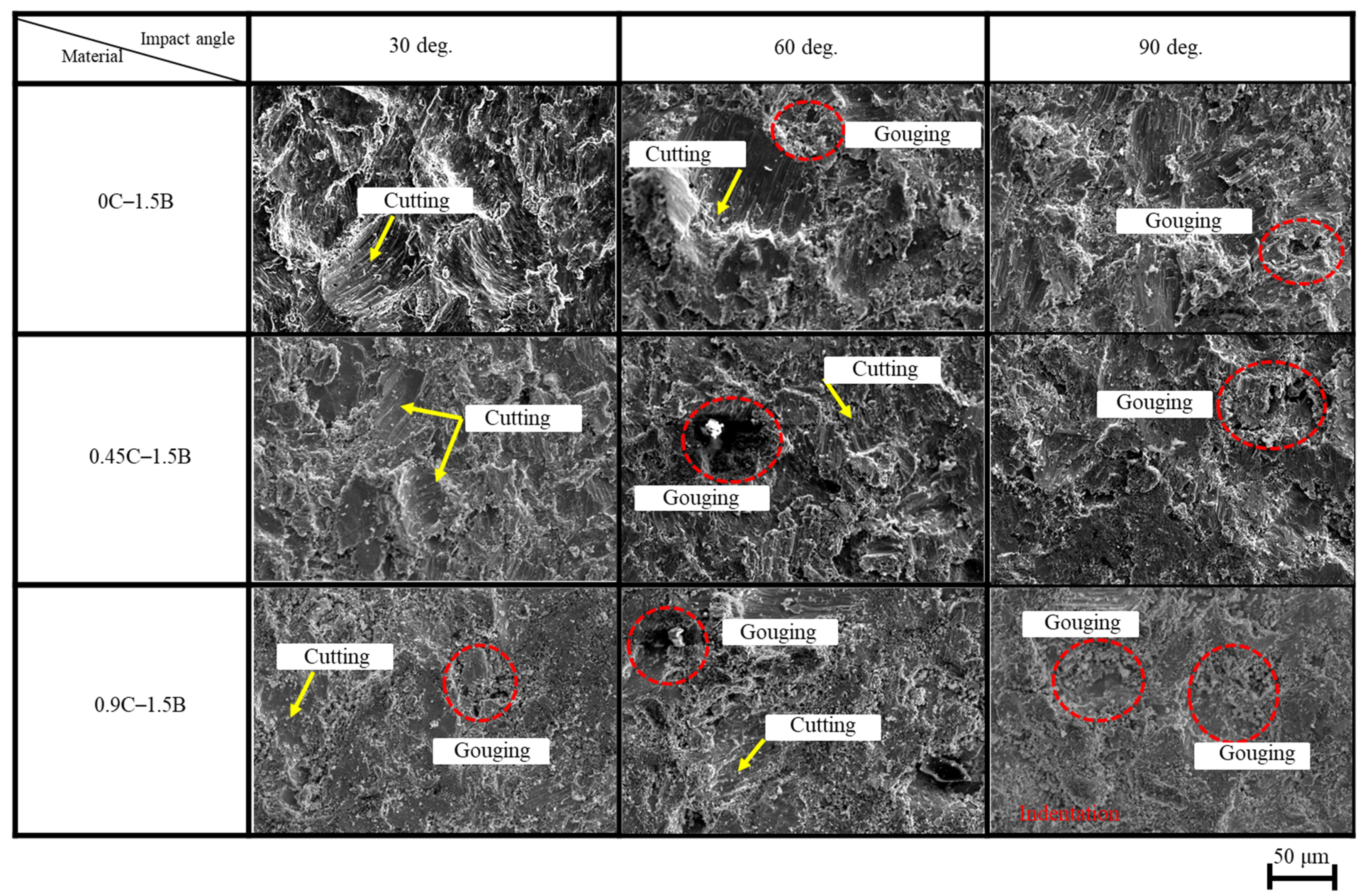
3.4. Erosive Wear Mechanism of Each Cast Alloy

From previous studies [2,31], it is known that it is important to investigate the wear mechanism of material in order to gain a better understanding of the process. Therefore, in this study, both the worn surface and the cross section of the most eroded surface area were observed.

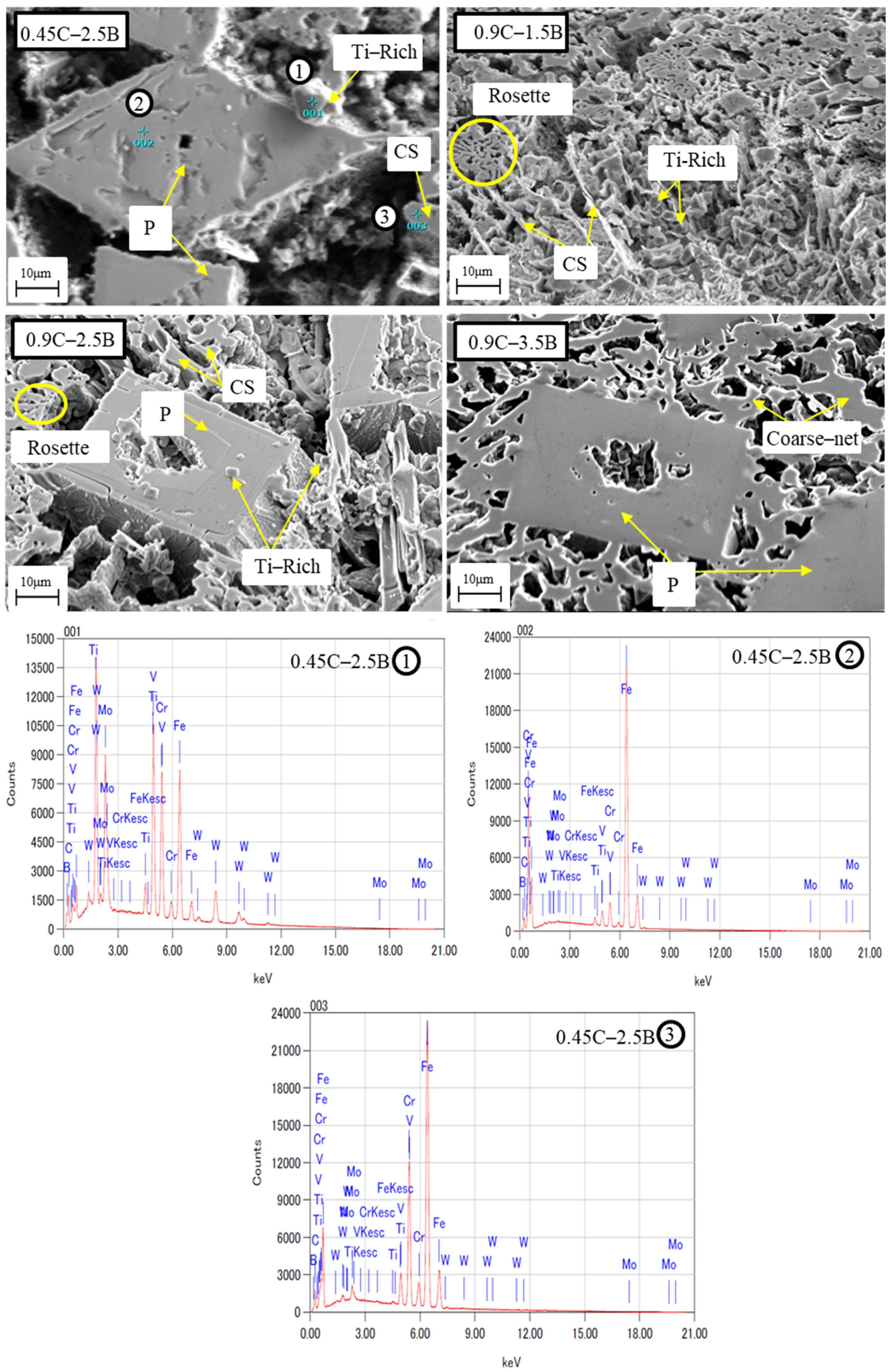
3.4.1. Worn-Surface Investigation

The wear surfaces of representative alloys are displayed in Figure 8. It can be seen that most of the cutting patterns can be found on the wear surface of 0.45C–1.5B after being tested at an impact angle of 30°. This means that the cast alloy experienced a micro-cutting mechanism at this impact angle. In contrast, there is only gouging pattern at 90° impact angle, caused by the micro-indentation mechanism. Meanwhile, cutting and gouging can be clearly seen at an impact angle of 60°. Since both mechanisms (cutting and indentation) occur simultaneously at an impact angle of 60°, this might be a factor in the highest erosive wear rate of 0.45C–1.5B. This is also implied for 0.45C–2.5B, 0.9C–3.5B, and 0C with the same addition of B. However, cutting and gouging can be seen at an impact angle of 30° in the case of 0.9C–1.5B. This indicates that the micro-cutting and gouging mechanisms occur simultaneously at this angle of impact. The gouging pattern becomes dominant, while the cutting pattern becomes less visible as the number of impact angle increases. The higher hardness level as the amount of C increases, as previously described, makes this alloy similar to a brittle material that has the highest wear rate at 90° impact angle. In addition, the worn surface of the 0C–1.5B and 0.45C–1.5B alloy is more severe than 0.9C–1.5B at all impact angles. Therefore, it can be said that a more severe wear surface indicates a material with lower erosion wear resistance.

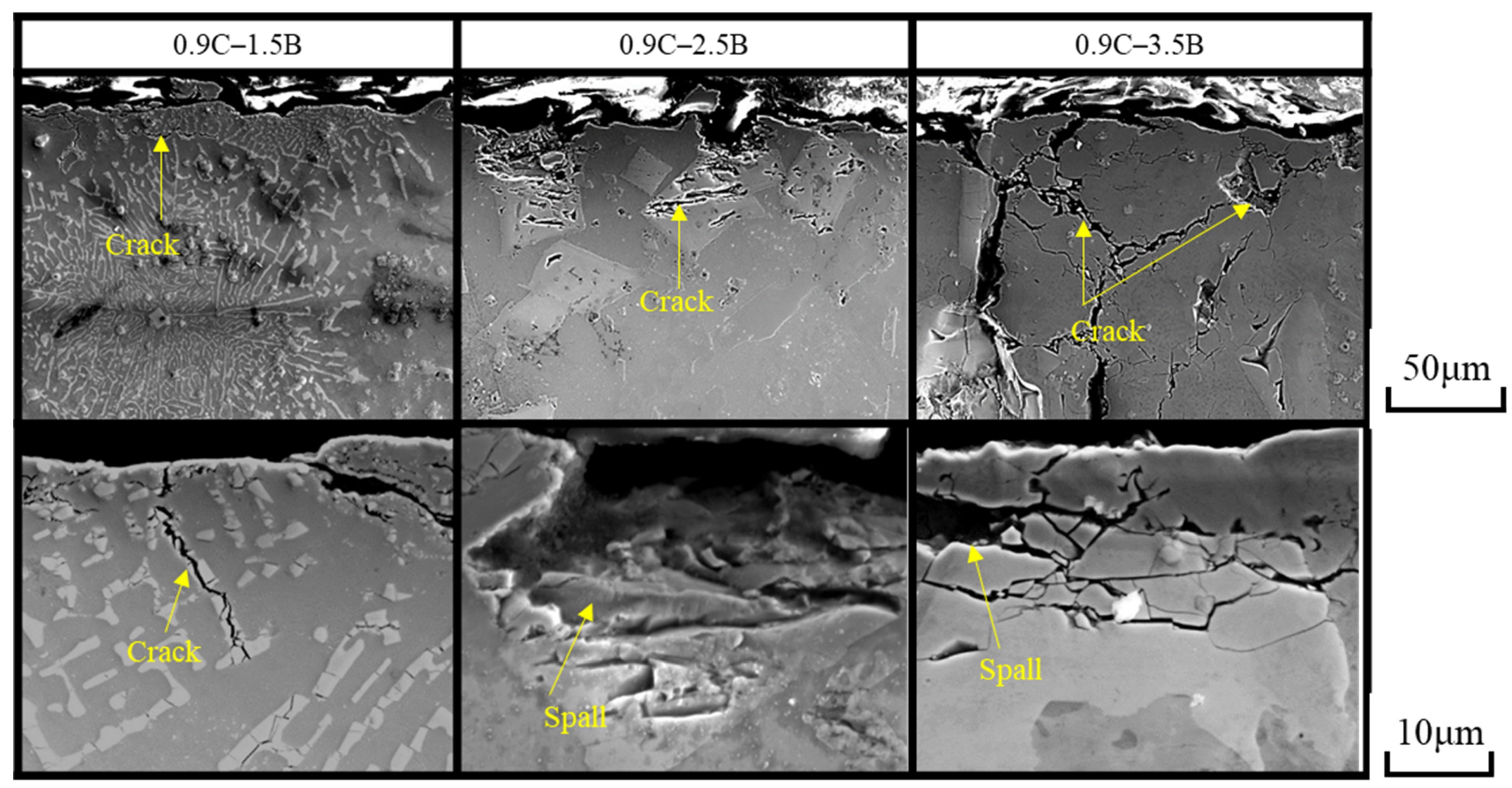
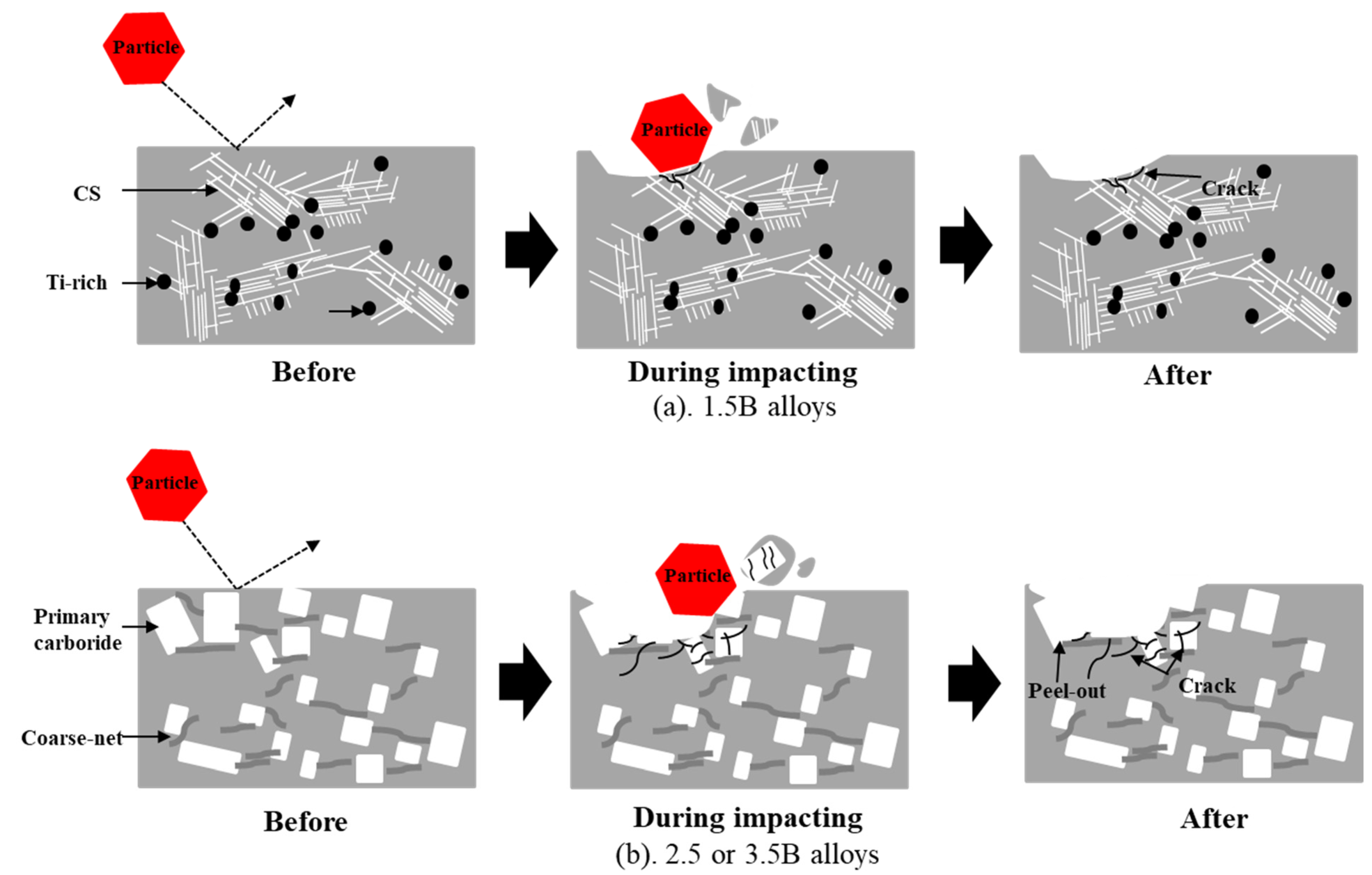
3.4.2. Cross-Section Investigation

In cross-section, as shown in Figure 9, the crack can be encountered underneath the worn surface of alloys owing to the continuous striking of the steel-grit (erodent). It gets worse as the amount of B increases. A clearer cross-section of a representative alloy can be seen at a lower magnification on the SEM micrograph. It shows that the crack mostly exists in the CS eutectic area of 0.9C. Meanwhile, it occurs on the P carborides in the case of 2.5B and 3.5B with the same amount of C. The appearance of cracking and spall might be due to brittleness of these hard phases. Moreover, the P borides seem to directly spall after the test. This indicates that the cast alloys containing more P borides will be easier to crack leading to lower erosive wear resistance. Therefore, it can be stated that the micro-cutting and indentation are the erosive wear mechanisms of this present studied alloy.
To simplify the explanation of the erosion wear behavior of cast alloys, a schematic of erosion wear has been drawn, as shown in Figure 10. It is understood that particles will erode all microstructure constituents (matrix and eutectic). During the impact process, the particles will first cut the ferrite matrix owing to a lower hardness compared to steel grit, and fracture the CS or R eutectic and borides/carborides. Then, they will simultaneously remove the eutectic and matrix leaving micro-cutting and cracks on the worn surface after testing. The increase in material hardness as the amount of C increases makes it difficult for the particles to cut the matrix and crack the eutectic, resulting in lower material loss. However, when the area of the P carboride is exposed to the eroding particles, it tends to crack or spall, resulting in a higher amount of material loss.

4. Conclusions

The erosive wear behavior of new HMCAs with different C and B contents was evaluated in this study. The results can be summarized as follows:
  • The hardness of the alloy was not directly dependent on the change in BVF. Instead, it was affected by the amount of C or B added. Alloys with more C or B will definitely have a higher hardness.
  • Based on impact angle, the highest wear rate in 0C and 0.45C with 1.5–3.5% B occurred at an impact angle of 60° due to gouging and indentation mechanisms occurring simultaneously. However, different results occurred in the case of 0.9C with the same amount of B, where the wear rate increased with increasing impact angle due to brittleness.
  • Based on the chemical composition, the wear resistance of the alloy increased with increasing C content due to higher hardness values. However, the reverse performance occurred when the addition of B exceeded the threshold (more than 1.5 wt.%) despite the higher hardness. This fact is due to the susceptibility to carbide cracking as the amount of B increases.
  • Overall, the alloy with the best erosion resistance was 0.9C–1.5B because it was more resistant to cracking and had appropriate hardness.

Author Contributions

Writing—original draft preparation, conceptualization, investigation, and reviewing and editing: R.H.P.; formal analysis and writing—review and editing: K.K.; conceptualization, resources, and supervision: K.S.; investigation, conceptualization: V.E. All authors have read and agreed to the published version of the manuscript.

Funding

This research received no external funding.

Institutional Review Board Statement

Not applicable.

Informed Consent Statement

Not applicable.

Data Availability Statement

The data presented in this study are available upon request from the corresponding author.

Conflicts of Interest

The authors declare no conflict of interest.

References

  1. Holmberg, K.; Erdemir, A. Influence of tribology on global energy consumption, cost and emissions. Friction 2017, 5, 263–284. [Google Scholar] [CrossRef]
  2. Kosel, T.H. Solid particle erosion. In Friction, Lubrication, and Wear Technology; ASM International: Materials Park, OH, USA, 1992; Volume 18, pp. 199–213. [Google Scholar]
  3. Murakami, T. Reducing Wear Through Material Selection and Geometric Design with Actual Lubrication Mode. In Biotribology of Natural and Artificial Joints; Elsevier: Amsterdam, The Netherlands, 2023; pp. 1–27. [Google Scholar] [CrossRef]
  4. Shimizu, K.; Xinba, Y.; Ishida, M.; Kato, T. High temperature erosion characteristic of surface treated SUS410 stainless steel. Wear 2011, 271, 1349–1356. [Google Scholar] [CrossRef]
  5. Yaer, X.; Shimizu, K.; Qu, J.; Wen, B.; Cao, X.; Kusumoto, K. Surface deformation micromechanics of erosion damage at different angles and velocities for aero-engine hot-end components. Wear 2019, 426–427, 527–538. [Google Scholar] [CrossRef]
  6. Verma, P.; Tyagi, R.; Mohan, S. Effect of microstructure, impact velocity and angle on erosive wear of medium carbon, dual phase and fully martensitic steels. Wear 2023, 518, 204645. [Google Scholar] [CrossRef]
  7. Sapate, S.G.; Ramarao, A.V. Erosive wear behaviour of weld hardfacing high chromium cast irons: Effect of erodent particles. Tribol. Int. 2006, 39, 206–212. [Google Scholar] [CrossRef]
  8. Walker, A.I.; Hambe, M. Effect of particles shape on slurry wear of white iron. Wear 2015, 332–333, 1021–1027. [Google Scholar] [CrossRef]
  9. Babu, P.S.; Basu, B.; Sundararajan, G. The influence of erodent hardness on the erosion behavior of detonation sprayed WC-12Co coatings. Wear 2011, 270, 903–913. [Google Scholar] [CrossRef]
  10. Ahmed, D.A.; Yerramalli, C.S. Experimental and computational analysis of the erosion behaviour of unidirectional glass fiber epoxy composites. Wear 2020, 462–463, 203525. [Google Scholar] [CrossRef]
  11. Divakar, M.; Agarwal, V.K.; Singh, S.N. Effect of material surface hardness on the erosion of AISI316. Wear 2005, 259, 110–117. [Google Scholar] [CrossRef]
  12. Bergami, L.B.; Lima, A.O.; Venturelli, B.N.; Machado, I.F.; Albertin, E.; Souza, R.M. Effect of carbide orientation during single scratch test in directionally solidified and heat-treated high chromium cast irons. Wear 2023, 523, 204823. [Google Scholar] [CrossRef]
  13. Shimizu, K.; Purba, R.H.; Kusumoto, K.; Year, X.; Ito, J.; Kasuga, H.; Gaqi, Y. Microstructural evaluation and high-temperature erosion characteristic of high chromium cast irons. Wear 2019, 426–427, 420–427. [Google Scholar] [CrossRef]
  14. Matsubara, Y.; Sasaguri, N.; Shimizu, K.; Yu, S.K. Solidification and abrasion wear of white cast irons alloyed with 20% carbide forming elements. Wear 2001, 250, 502–510. [Google Scholar] [CrossRef]
  15. Kusumoto, K.; Shimizu, K.; Yaer, X.; Hara, H.; Tamura, K.; Kawai, H. High erosion-oxidation performance of Fe-based Nb or V containing multicomponent alloys with Co addition at 1173 K. Mater. Des. 2015, 88, 366–374. [Google Scholar] [CrossRef]
  16. Zang, Y.; Shimizu, K.; Kusumoto, K.; Tamura, K.; Hara, H.; Ito, J. Effect of Co addition on high temperature erosive wear characteristics of Fe-C-Cr-Mo-W-V multi-component white cast iron. Mater. Trans. 2017, 58, 927–931. [Google Scholar] [CrossRef]
  17. Purba, R.H.; Shimizu, K.; Kusumoto, K.; Gaqi, Y.; Huq, M.J. A study of the three-body abrasive wear resistance of 5V/5Nb-5Cr-5Mo-5W-5Co-Fe multicomponent cast alloys with different carbon percentages. Materials 2023, 16, 3102. [Google Scholar] [CrossRef]
  18. Yang, H.; Wang, X.; Jin-bo, Q.U. Effect of boron on CGHAZ microstructure and toughness of high strength low alloy steels. J. Iron Steel Res. Int. 2014, 28, 787–792. [Google Scholar] [CrossRef]
  19. Hwang, B.; Suh, D.; Kim, S. Austenitizing temperature and hardenability of low-carbon boron steels. Scr. Mater. 2011, 64, 1118–1120. [Google Scholar] [CrossRef]
  20. Baker, I. Alloy phase diagrams. In ASM Handbook; ASM International: Materials Park, OH, USA, 1992; Volume 3, p. 281. [Google Scholar]
  21. Kulka, M.; Makuch, N.; Piasecki, A. Nanomechanical characterization and fracture toughness of FeB and Fe2B iron borides produced by gas boriding of armco iron. Surf. Coat Technol. 2017, 325, 515–532. [Google Scholar] [CrossRef]
  22. Lakeland, K.D.; Graham, E.; Heron, A. Mechanical Properties and Microstructures of a Series of Fe-C-B Alloys; The University of Queensland: Brisbane, Australia, 1992. [Google Scholar]
  23. Li, Y.X.; Liu, Z.L.; Chen, X. Development of boron white cast iron. Int. J. Cast Met. Res. 2008, 21, 67–70. [Google Scholar] [CrossRef]
  24. Liu, Z.; Li, Y.; Chen, X.; Hu, K. Microstructure and mechanical properties of high boron white cast iron. Mater. Sci. Eng. A 2008, 486, 112–116. [Google Scholar] [CrossRef]
  25. Liu, Z.; Chen, X.; Li, Y.; Hu, K. Effect of chromium on microstructure and properties of high boron white cast iron. Metall. Mater. Trans. A 2008, 39, 636–641. [Google Scholar] [CrossRef]
  26. Ren, X.; Tang, S.; Fu, H.; Xing, J. Effect of titanium modification on microstructure and impact toughness of high-boron multi-component alloy. Metals 2021, 11, 193. [Google Scholar] [CrossRef]
  27. Liu, Y.; Li, B.H.; Li, J. Effect of titanium on the ductilization of Fe–B alloys with high boron content. Mater. Lett. 2010, 64, 1299–1301. [Google Scholar] [CrossRef]
  28. Efremenko, V.G.; Chabak, Y.G.; Shimizu, K.; Golinskyi, M.A.; Lekatou, A.G.; Petryshynets, I.; Efremenko, B.V.; Halfa, H.; Kusumoto, K.; Zurnadzhy, V.I. The novel hybrid concept on designing advanced multi-component cast irons: Effect of boron and titanium (Thermodynamic modelling, microstructure and mechanical property evaluation). Mater. Charact. 2023, 197, 112691. [Google Scholar] [CrossRef]
  29. Chabak, Y.G.; Shimizu, K.; Efremenko, V.G.; Golinskyi, M.A.; Kusumoto, K.; Zurnadzhy, V.I.; Efremenko, A.V. Microstructure and phase elemental distribution in high-boron multi-component cast irons. Int. J. Miner. Metall. Mater. 2022, 29, 78–87. [Google Scholar] [CrossRef]
  30. Chabak, Y.; Petryshynets, I.; Efremenko, V.; Golinskyi, M.; Shimizu, K.; Zurnadzhy, V.; Sili, I.; Halfa, H.; Efremenko, B.; Puchy, V. Investigations of Abrasive Wear Behaviour of Hybrid High-Boron Multi-Component Alloys: Effect of Boron and Carbon Contents by the Factorial Design Method. Materials 2023, 16, 2530. [Google Scholar] [CrossRef]
  31. Purba, R.H.; Shimizu, K.; Kusumoto, K.; Todaka, T.; Shirai, M.; Hara, H.; Ito, J. Erosive wear characteristics of high-chromium based multi-component white cast irons. Tribol. Int. 2021, 159, 106982. [Google Scholar] [CrossRef]
  32. Georgatis, E.; Lekatou, A.; Karantzalis, A.E.; Petropoulos, H.; Katsamakis, S.; Poulia, A. Development of a cast Al–Mg2Si–Si in situ composite: Microstructure, heattreatment, and mechanical properties. J. Mater. Eng. Perform. 2013, 22, 729–741. [Google Scholar] [CrossRef]
  33. Kim, B.J.; Jung, S.S.; Hwang, J.H.; Park, Y.H.; Lee, Y.C. Effect of eutectic Mg2Si phase modification on the mechanical properties of Al–8Zn–6Si–4Mg–2Cu cast alloy. Metals 2019, 9, 32. [Google Scholar] [CrossRef]
  34. Purba, R.H.; Shimizu, K.; Kusumoto, K.; Gaqi, Y.; Todaka, T. Effect of boron addition on three-body abrasive wear characteristics of high chromium based multi-component white cast iron. Mater. Chem. Phys. 2022, 275, 125232. [Google Scholar] [CrossRef]
  35. Robert, J.K. Wood. In ASM Handbook: Friction, Lubrication, and Wear Technology; ASM International: Materials Park, OH, USA, 2017; Volume 18, pp. 266–289. [Google Scholar]
Figure 1. Schematic of shot-blast erosive wear machine test.
Lubricants 11 00243 g001
Figure 2. Metallographic microstructure of each HMCA obtained by SEM.
Lubricants 11 00243 g002
Figure 3. Element distribution on representative HMCA microstructure obtained by SEM-EDS mapping.
Lubricants 11 00243 g003
Figure 4. The bulk observation of 0.45C–2.5B, 0.9C–1.5B, 0.9C–2.5B, and 0.9C–3.5B through lower magnification SEM after deep-etching process and point analysis peak of 0.45C–2.5B as the representative material.
Lubricants 11 00243 g004
Figure 5. Relationship of BVF and Vickers hardness of each HMCA.
Lubricants 11 00243 g005
Figure 6. Erosive wear rate of each HMCA as a function of impact angle.
Lubricants 11 00243 g006
Figure 7. Comparison of erosive wear rate of each alloy at 60° impact angle.
Lubricants 11 00243 g007
Figure 8. Observation of the erosive wear mechanism of representative alloys through the worn surface at three different impact angles.
Lubricants 11 00243 g008
Figure 9. Observation of the erosive wear mechanism of a representative alloy through a cross section at an impact angle of 60°.
Lubricants 11 00243 g009
Figure 10. Schematic of the erosive wear mechanism of each alloy.
Lubricants 11 00243 g010
Table 1. Chemical composition of each HMCA (wt.%).
Sample NameCBCrVMoWTiFe
0C–1.5B0.081.519.805.214.805.012.45Bal.
0C–2.5B0.072.4310.105.145.024.952.37Bal.
0C–3.5B0.103.5610.365.074.934.862.59Bal.
0.45C–1.5B0.441.4710.045.044.784.792.54Bal.
0.45C–2.5B0.442.3810.125.015.215.012.43Bal.
0.45C–3.5B0.453.3510.095.315.135.012.52Bal.
0.9C–1.5B0.851.569.875.045.025.032.67Bal.
0.9C–2.5B0.812.519.595.105.215.052.50Bal.
0.9C–3.5B0.933.3310.125.055.074.852.51Bal.
Disclaimer/Publisher’s Note: The statements, opinions and data contained in all publications are solely those of the individual author(s) and contributor(s) and not of MDPI and/or the editor(s). MDPI and/or the editor(s) disclaim responsibility for any injury to people or property resulting from any ideas, methods, instructions or products referred to in the content.

