Article

Research on the Nonlinear Stiffness Characteristics of Double-Row Angular Contact Ball Bearings under Different Working Conditions

1
Key Laboratory of Education Ministry for Modern Design and Rotor-Bearing System, Xi’an Jiaotong University, Xi’an 710049, China
2
School of Mechanical Engineering, Xi’an Jiaotong University, Xi’an 710049, China
*
Authors to whom correspondence should be addressed.
Lubricants 2023, 11(2), 44; https://doi.org/10.3390/lubricants11020044
Submission received: 28 December 2022 / Revised: 22 January 2023 / Accepted: 26 January 2023 / Published: 28 January 2023
(This article belongs to the Special Issue Advances in Bearing Lubrication and Thermodynamics 2023)

Abstract

:
To study the variation rules of nonlinear stiffness of double-row angular contact ball bearings (DR-ACBB), this paper proposed a general mathematic model for DR-ACBB under three different configurations based on the improved quasi-static model of ball bearings, an explicit expression stiffness matrix of DR-ACBB is analytically derived, and a double-layer nested iterative algorithm based on the Newton–Raphson method is designed to realize the efficient solution of the proposed model. Then, the effects of the preload, speeds, and loads on the nonlinear stiffness variations of DR-ACBB under different arrangements are comparatively analyzed. The results show that DR-ACBB under the DB and DF configurations have the same variation rule in axial and radial stiffness; that is, a nonlinear soft-spring stiffness characteristic (i.e., the stiffness decreases with the external load) within the low-speed range and light load condition, and a nonlinear hard spring stiffness characteristic (i.e., the stiffness increases with the external load) within the high-speed range or heavy load condition.

1. Introduction

As the core functional component of various rotating machinery systems, double-row angular contact ball bearings (DR-ACBB) have been widely used in rail transportation, CNC machine tools, and aerospace and other fields. Compared with traditional single-row angular contact ball bearings, DR-ACBB show better rigidity and carrying capacity. Due to the strong nonlinear coupling between the loads and deformations of single-row angular contact ball bearings (SR-ACBB), the stiffness characteristics of DR-ACBB cannot be obtained by the linear superposition of two single ball bearings. Unfortunately, studies on DR-ACBB are relatively few, and only a small number of static simplified models have been reported in recent years.
Bercea [1] proposed a unified model for different types of double-row rolling bearings under a face-to-face arrangement; however, a study on the stiffness formulation of double-row rolling bearings was not involved. Gunduz and Singh [2,3] conducted a comprehensive study on the mechanical modeling and stiffness matrix calculation for static DR-ACBB, and the effects of the preload and arrangement forms are detailed, discussed, and analyzed. On this basis, Dick [4] presented a simplified mathematical model to predict the load distribution, stiffness variations, and vibration responses for DR-ACBB with raceway defects of varying length, depth, and surface roughness. Xu et al. [5] further studied the influence of ring angular misalignments on the load distribution and stiffness coefficients for DR-ACBB. Above all, not only the effects of ball inertia forces have been ignored—the relationship between DR-ACBB and SR-ACBB has not been explicitly determined.
In order to accurately predict the mechanical and stiffness characteristics of DR-ACBB at different speed ranges, the influence of the centrifugal forces and gyroscopic moments of internal balls need to be fully considered. Furthermore, according to the structure features of DR-ACBB, the mechanics and motion states of the SR-ACBB should be determined first. Different from the study on DR-ACBB, large numbers of the modeling methods and characteristics analyses of SR-ACBB have been widely reported [6,7,8,9,10,11,12,13,14,15,16,17,18]. Among them, due to its high computational efficiency and accuracy, the improved quasi-static model based on the no-macro-sliding hypothesis has been widely used in load distribution calculations and stiffness characteristic analyses [10,13].
As the basic aspect of the dynamic modeling and characteristic analysis of bearing and rotor systems, research on the stiffness matrix of ball bearing has been paid attention to for a long time [19,20,21,22,23,24,25,26,27,28,29,30,31,32,33,34]. Especially in recent years, multi-degree-of-freedom stiffness matrix calculations based on analytical differential [24,25,26,27,28] and numerical difference [29,30,31] methods have become a trend in this field. Compared with the numerical method, the analytical method has higher calculation efficiency, stability, and accuracy. However, all the above studies were only conducted for SR-ACBB, mainly focusing on stiffness softening behaviors; that is, the stiffness of ball bearings decrease as their rotating speed increases. However, an analysis of the nonlinear stiffness characteristics of ball bearings is rarer [32]. Considering the significant difference between the dynamic response of nonlinear and linear systems, it is impossible to accurately predict the dynamic characteristics of the bearing and rotor support system based on linear stiffness assumptions. Furthermore, DR-ACBB can have different configurations, which may lead to more abundant nonlinear stiffness characteristics for DR-ACBB under different load conditions and speed ranges. Therefore, it is of great significance to systematically and comprehensively study the nonlinear stiffness characteristics of DR-ACBB.
This paper presents a comprehensive study on the nonlinear stiffness characteristics of DR-ACBB under three different arrangements. First, based on the improved quasi-static model of SR-ACBB, the load and displacement relationships between DR-ACBB and two SR-ACBB are given by the vector transformation under multi-coordinate systems. Then, the analytical derivation of the stiffness matrix for DR-ACBB under different arrangements is presented, and a double-layer nested iterative algorithm based on Newton–Raphson is designed for the high-efficiency solution of the proposed model. At last, the influences of the rotating speed, preload, and external force on the nonlinear stiffness characteristics of DR-ACBB under different arrangements are comparatively analyzed.

2. Theoretical Analysis

The three typical configuration forms of DR-ACBB are shown in Figure 1: (i) back-to-back (DB) arrangement; (ii) face-to-face (DF) arrangement; and (iii) tandem (DT) arrangement. To build a universal model of DR-ACBB in the above different configurations, the following assumptions are given to simplify the complexity:
(1)
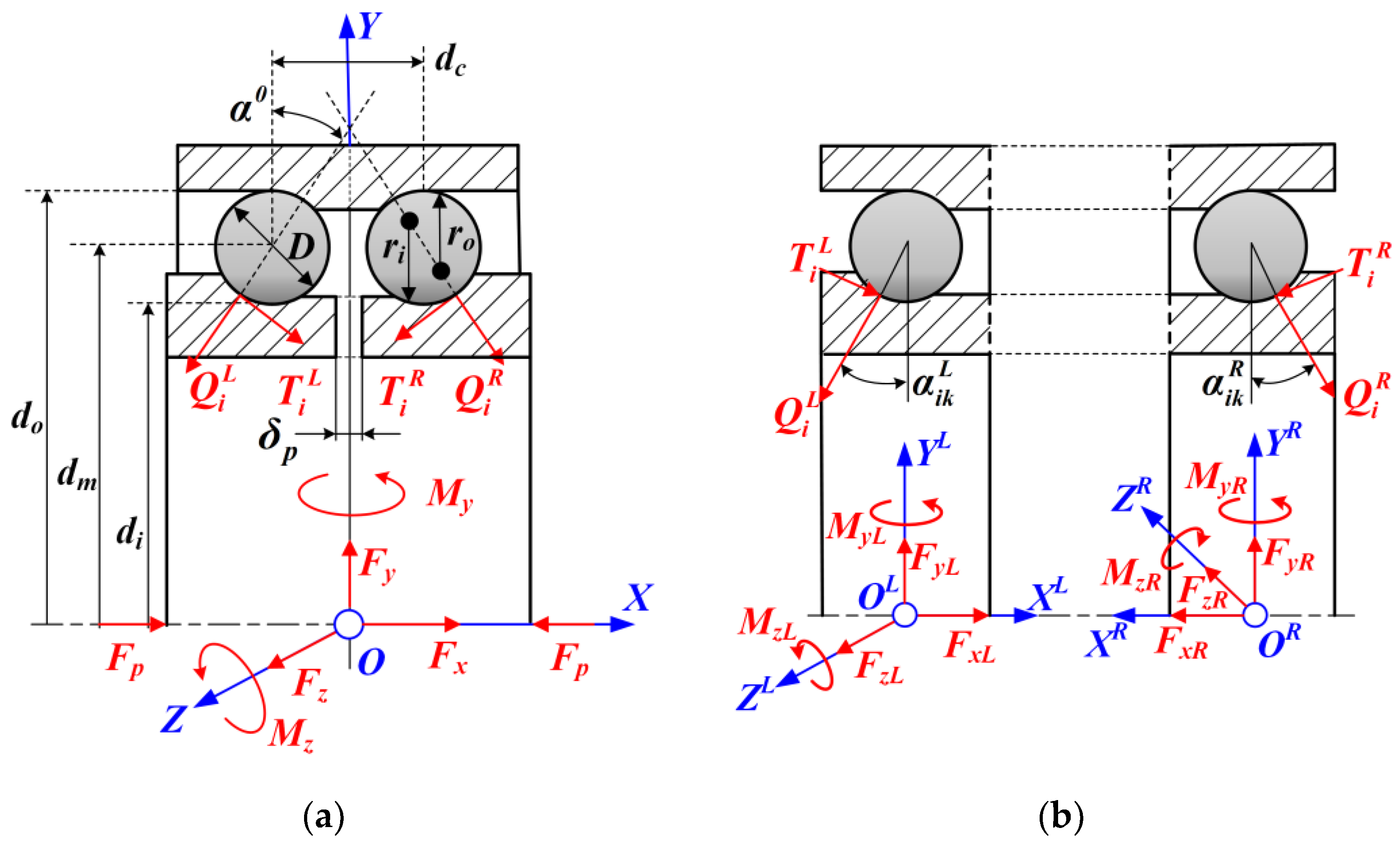
Two SR-ACBBs have the same structural parameters, that is, the raceway contact curvature radii ri and ro, the raceway contact diameters di and do, and the ball diameter and number D and Z, respectively;
(2)
The influence of the lubrication and cage is not considered;
(3)
The outer raceway is fixed while the inner ring moves and rotates with the central shaft.
In order to further improve the supporting rigidity and operation accuracy, DR-ACBB is always designed with a split inner raceway, which provides a lock nut or spacer convenient for the axial preloading [3,18]. Therefore, compared with SR-ACBB, DR-ACBB have two additional geometry parameters as presented in Figure 2: the center distance between two rows of rolling elements (dc) and the axial clearance of the split inner ring ( δ p ). During the installation process of double-row ball bearings, the axial clearance δ p needs to be eliminated by axial locking force to achieve effective pre-tightening.

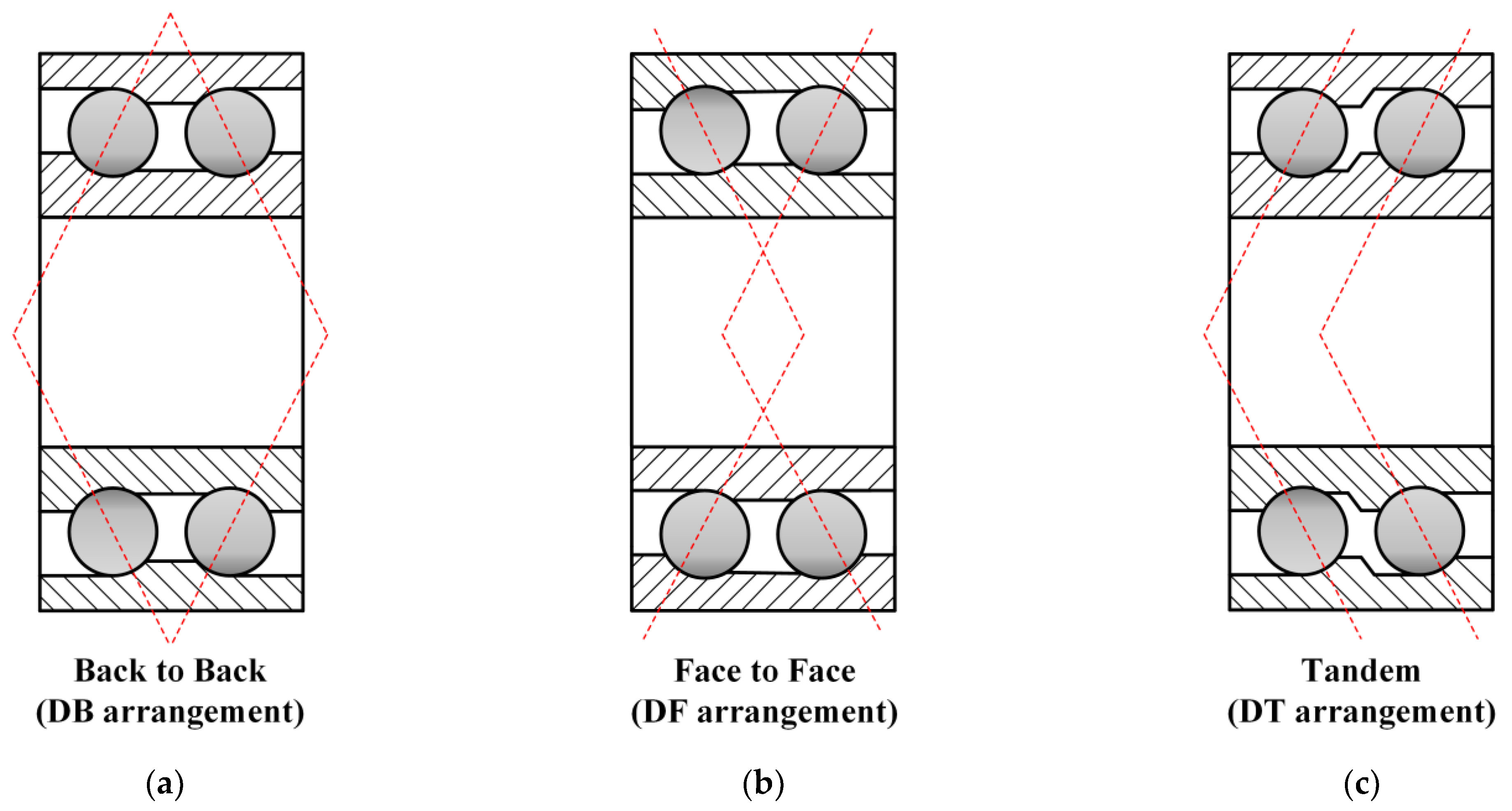
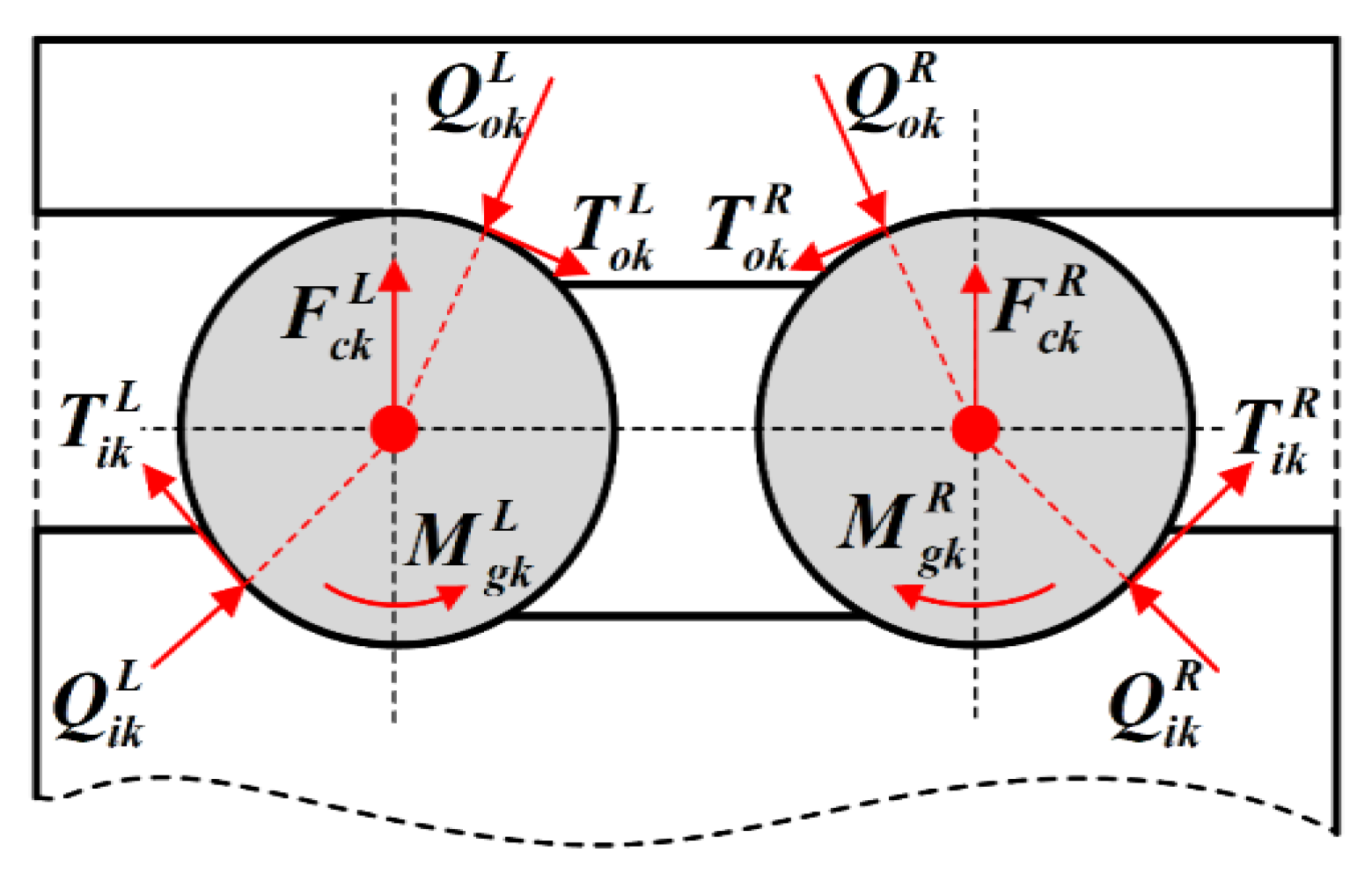
2.1. Mechanics Analysis of DR-ACBB

As shown in Figure 2, the DR-ACBB under the DB configuration are chosen as an example to illustrate the detailed modeling process of DR-ACBB under variation operating conditions. At first, it is assumed that DR-ACBB are subjected to arbitrary combined loads at their geometric center, and then two type of coordinate systems are established to aid the derivation the equilibrium equations of DR-ACBB: (i) the global coordinate system of DR-ACBB: O-XYZ; (ii) the local coordinate systems of the single-row ACBB: OL-XLYLZL and OR-XRYRZR. Furthermore, the YL and YR axes, respectively, pass through the ball centers of the left and right side of the ACBB. On this basis, the mechanical equations of the moving inner raceway for DR-ACBB under a DB arrangement can be given as:
{ F x = k = 1 Z [ ( Q i k L sin α i k L T i k L cos α i k L ) ( Q i k R sin α i k R T i k R cos α i k R ) ] F y = k = 1 Z [ ( Q i k L cos α i k L + T i k L sin α i k L ) + ( Q i k R cos α i k R + T i k R sin α i k R ) ] cos ψ k F z = k = 1 Z [ ( Q i k L cos α i k L + T i k L sin α i k L ) ( Q i k R cos α i k R + T i k R sin α i k R ) ] sin ψ k M y = k = 1 Z { [ d m D cos α i k L 2 ( Q i k L sin α i k L T i k L cos α i k L ) + d m D cos α i k R 2 ( Q i k R sin α i k R T i k R cos α i k R ) ] + …… [ d c + D sin α i k L 2 ( Q i k L cos α i k L + T i k L sin α i k L ) + d c + D sin α i k R 2 ( Q i k R cos α i k R + T i k R sin α i k R ) ] } sin ψ k M z = k = 1 Z { [ d m D cos α i k L 2 ( Q i k L sin α i k L T i k L cos α i k L ) d m D cos α i k R 2 ( Q i k R sin α i k R T i k R cos α i k R ) ] + …… [ d c + D sin α i k L 2 ( Q i k L cos α i k L + T i k L sin α i k L ) + d c D sin α i k R 2 ( Q i k R cos α i k R + T i k R sin α i k R ) ] } cos ψ k
where Q and T are the ball raceway’s normal contact load and tangential friction load, α and ψ are the contact angle and position angle of ball, and dm and D are the pitch diameter and ball diameter, respectively. Furthermore, in this paper, unless otherwise stated, the subscripts i and o, respectively, indicate the parameters used for inner and outer ball raceway action analysis, and the subscript k indicates the parameters used for the kth ball. The superscripts L and R, respectively, denote the parameters used for modeling the left-side and right-side DR-ACBB.
To simplify the above mechanical equations of DR-ACBB, the mechanical equations of two SR-ACBBs need to be determined first. As shown in Figure 2b, it is assumed that the restoring force vectors generated by two SR-ACBBs at the local coordinate center points OL and OR are written as FL = {FxL, FyL, FzL, MyL, MzL} and FR = {FxR, FyR, FzR, MyR, MzR}, respectively. Then, the expressions of the mechanical equations of two SR-ACBBs are presented in Equations (2)–(5):
{ F x L = 1 Z F a k L F y L = 1 Z F r k L cos ψ k F z L = 1 Z F r k L s i n ψ k M y L = 1 Z ( d m D cos α i k L 2 F a k L + D sin α i k L 2 F r k L ) sin ψ k M z L = 1 Z ( d m D cos α i k L 2 F a k L + D sin α i k L 2 F r k L ) cos ψ k
with
{ F a k L = Q i k L sin α i k L T i k L cos α i k L F r k L = Q i k L cos α i k L + T i k L sin α i k L
and
{ F x R = 1 Z F a k R F y R = 1 Z F r k R cos ψ k F z R = 1 Z F r k R s i n ψ k M y R = 1 Z ( d m D cos α i k R 2 F a k R + D sin α i k R 2 F r k R ) sin ψ k M z R = 1 Z ( d m D cos α i k R 2 F a k R + D sin α i k R 2 F r k R ) cos ψ k
with
{ F a k R = Q i k R sin α i k R T i k R cos α i k R F r k R = Q i k R cos α i k R + T i k R sin α i k R
Substituting Equations (2) and (4) into Equation (1), then one can obtain:
{ F x = F x L F x R F y = F y L + F y R F z = F z L F z R M y = M y L + M y R + d c 2 ( F z L + F z R ) M z = M z L M z R d c 2 ( F y L F y R )
The above Equation (6) can be further rewritten to the following matrix operation:
F T = N 1 ( d c 2 ) × F L T + N 2 ( d c 2 ) × F R T
with
N 1 ( d c 2 ) = [ 1 0 0 0 0 0 1 0 0 0 0 0 1 0 0 0 0 d c 2 1 0 0 d c 2 0 0 1 ] ,   N 2 ( d c 2 ) = [ 1 0 0 0 0 0 1 0 0 0 0 0 1 0 0 0 0 d c 2 1 0 0 d c 2 0 0 1 ]
Furthermore, the displacement vectors (dL and dR) of two SR-ACBBs at the local coordinate center points OL and OR can be calculated by the relative displacement vector of DR-ACBB at the global coordinate center points O (d = { δ x , δ y , δ z , θ y , θ z }):
d L T = [ δ x L δ y L δ z L θ y L θ z L ] = [ 0.5 δ P + δ x δ y d c 2 θ z δ z + d c 2 θ y θ y θ z ] = N 1 T ( d c 2 ) × d + [ 0.5 δ P 0 0 0 0 ]
d R T = [ δ x R δ y R δ z R θ y R θ z R ] = [ 0.5 δ P δ x δ y + d c 2 θ z δ z + d c 2 θ y θ y θ z ] = N 2 T ( d c 2 ) × d + [ 0.5 δ P 0 0 0 0 ]
Based on the above equations, it can be found that the relative displacement vectors of two SR-ACBBs at the local coordinate center points OL and OR can be determined by the matrix transformation of the relative displacement vector of DR-ACBB. Furthermore, the same initial preload displacement ( δ p / 2 ) is also considered in the relative displacement vector calculation of two SR-ACBB.
Similarly, the ring mechanical equations of DR-ACBB under DF and DT arrangements can also been given in a simplified matrix formation, as follows:
i.
DF arrangement:
F T = N 3 ( d c 2 ) × F L T + N 4 ( d c 2 ) × F R T
d L T = [ δ x L δ y L δ z L θ y L θ z L ] = [ 0.5 δ p δ x δ y d c 2 θ z δ z d c 2 θ y θ y θ z ] = N 3 T ( d c 2 ) × d T + [ 0.5 δ p 0 0 0 0 ]
d R T = [ δ x R δ y R δ z R θ y R θ z R ] = [ 0.5 δ p + δ x δ y + d c 2 θ z δ z d c 2 θ y θ y θ z ] = N 4 T ( d c 2 ) × d T + [ 0.5 δ p 0 0 0 0 ]
ii.
DT arrangement:
F T = N 1 ( d c 2 ) × F L T + N 4 ( d c 2 ) × F R T
d L T = [ δ x L δ y L δ z L θ y L θ z L ] = [   0 . 5 δ p + δ x δ y d c 2 θ z δ z + d c 2 θ y θ y θ z ] = N 1 T ( d c 2 ) × d T + [ 0.5 δ p 0 0 0 0 ]
d R T = [ δ x L δ y L δ z L θ y L θ z L ] = [ 0.5 δ p + δ x δ y + d c 2 θ z δ z d c 2 θ y θ y θ z ] = N 4 T ( d c 2 ) × d T + [ 0.5 δ p 0 0 0 0 ]
where the transfer matrices N3 and N4 used in the above expressions are written as:
N 3 ( d c 2 ) = [ 1 0 0 0 0 0 1 0 0 0 0 0 1 0 0 0 0 d c 2 1 0 0 d c 2 0 0 1 ] ,   N 4 ( d c 2 ) = [ 1 0 0 0 0 0 1 0 0 0 0 0 1 0 0 0 0 d c 2 1 0 0 d c 2 0 0 1 ]
Then, to further determine the ball raceway’s normal contact loads and tangential friction loads, the force analysis of the local balls in DR-ACBB needs to be conducted. As shown in Figure 3, taking the kth ball inside the left-side ACBB to build the local mechanical equations [9]:
{ Q i k L sin α i k L T i k L cos α i k L Q o k L sin α o k L + T o k L cos α o k L = 0 Q i k L cos α i k L + T i k L sin α i k L Q o k L cos α o k L T o k L sin α o k L + F c k L = 0
where Fc is the ball centrifugal force, and then the ball raceway’s normal contact load Q and tangential friction load T can be further given as [13]:
{ Q i k L = K i k L ( δ i k L ) 3 2 Q o k L = K o k L ( δ o k L ) 3 2 ,   { T i L = 2 Q i k L Q i k L + Q i k L M g k L D T o L = 2 Q o k Q i k L + Q o k L M g k L D
In addition, the geometric position change of the kth ball inside the left-side ACBB for DR-ACBB under a DB arrangement is shown in Figure 4, and the initial positions of the inner-ring’s curvature center and ball center are changed from points and O b k L to points O ˙ i k L and O ˙ b k L , respectively. Therefore, the ball raceway’s normal deformation is given as:
{ δ i k L = [ ( A 1 k L X 1 k L ) 2 + ( A 2 k L X 2 k L ) 2 ] 1 / 2 ( r i 0.5 D ) δ o k L = [ ( X 1 k L ) 2 + ( X 2 k L ) 2 ] 1 / 2 ( r o 0.5 D )
with
{ A 1 k L = ( r i + r o D ) sin α 0 + δ x L + 0.5 d m sin ψ k θ y L 0.5 d m cos ψ k θ z L A 2 k L = ( r i + r o D ) cos α 0 + cos ψ k δ y L + sin ψ k δ z L
where α 0 is the static initial contact angle of DR-ACBB without preload.
Furthermore, in order to ensure the stability and convergence of the subsequent iterative calculation, the ball raceway’s actual contact states need to be judged to cover the possible ball raceway separation [35]:
{ δ i k L = 0 δ i k L = eps i f [ ( A 1 k L X 1 k L ) 2 + ( A 2 k L X 2 k L ) 2 ] 1 / 2 ( r i 0.5 D ) [ ( X 1 k L ) 2 + ( X 2 k L ) 2 ] 1 / 2 ( r o 0.5 D )
In the above expression, a small real number of eps is set to ensure the positive contact deformation between the ball and outer ring (i.e., the ball never separates from the outer ring due to the inertia force).
In order to shorten the article space, this paper will not repeat the derivation process of the ball inside the right-side ACBB.

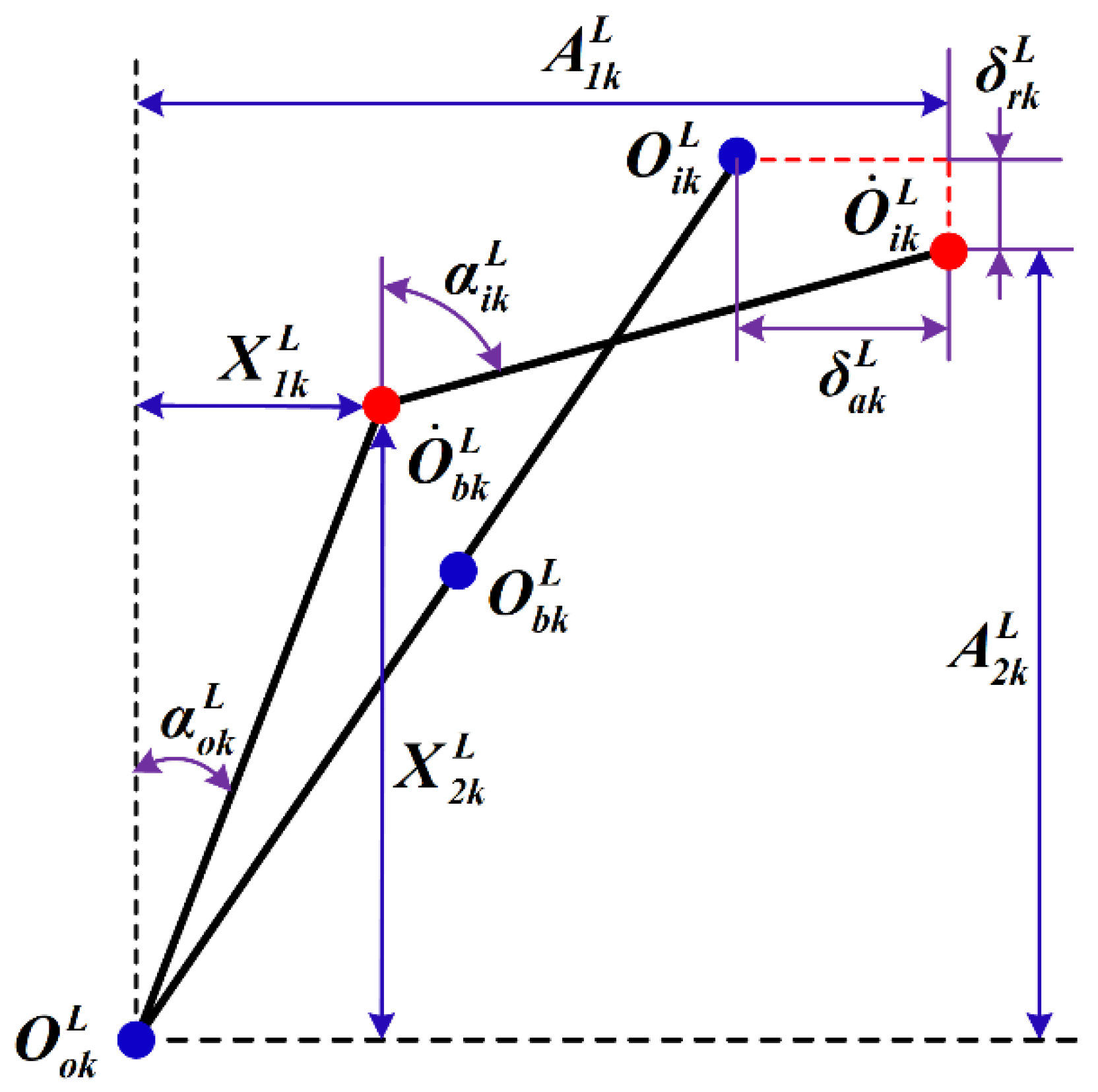
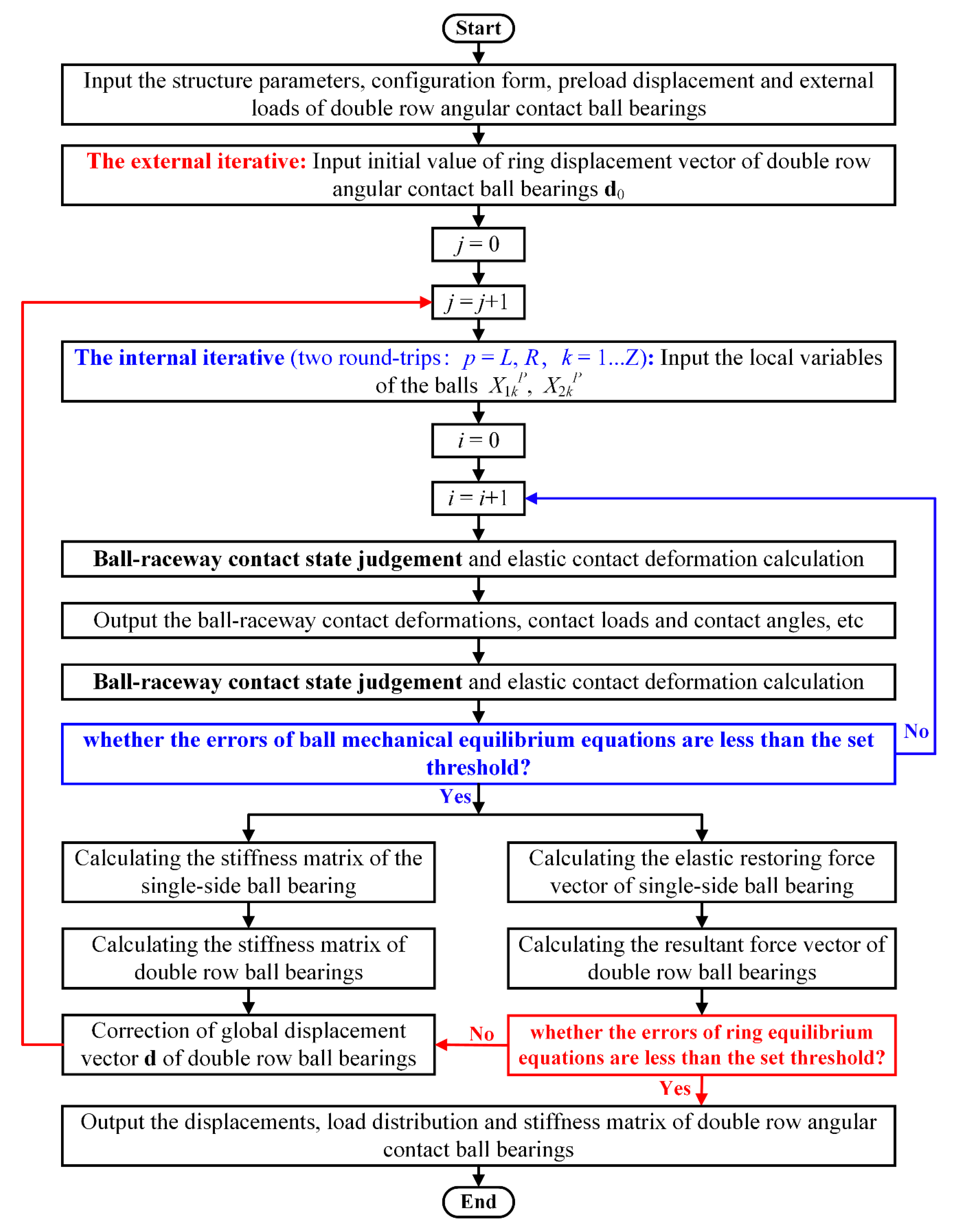
2.2. Iterative Calculation of the Proposed Model

In order to calculate the load distribution and deformation of DR-ACBB, two kinds of nonlinear equations need to be solved simultaneously: (1) the equilibrium equations of balls (i.e., Equation (18), and the number of equations is 4*Z); (2) the ring equilibrium equations (i.e., Equation (7)/Equation (11)/Equation (14), and the number of equations is 5). Therefore, how to construct a reasonable iterative algorithm to ensure the efficient and stable solution of the above equations is also a key research direction in this paper.
As shown in Figure 5, the detailed calculation process based on the two-layer nested iterative algorithm used in this paper is presented. The inner iteration is used to solve the ball equilibrium equations and the outer iteration is used to solve the ring equilibrium equations. Through further observation, both the displacement vector d and stiffness matrix K of DR-ACBB play an important role in the iterative operation. The displacement vector d is continuously modified through the stiffness matrix K until the iteration errors are less than the set threshold value, and the stiffness matrix K needs to be updated continuously by the calculation results of the inner iteration. Furthermore, the parallel calculation scheme can be used in ball mechanical equations solutions to further improve the calculation efficiency.

2.3. Analytical Formulation of the Stiffness Matrix of DR-ACBB

To calculate the analytical expression of the stiffness matrix of DR-ACBB, the explicit relationship of the stiffness matrices between DR-ACBB and SR-ACBBs need to be determined first. As the typical multi-degree-of-freedom nonlinear system, the variation stiffness matrix K of DR-ACBB are given as the Jacobian matrix of the external load vector F to the relative displacement vector d:
K = F d = ( F x , F y , F z , M y , M z ) ( δ x , δ y , δ z , θ y , θ z )
Taking DR-ACBB under a DB configuration as an example, according to Equations (7), (9), and (10), the above expression can be further extended as follows:
[ K ] DB = [ F d ] DB = N 1 F L d + N 2 F R d
with
{ F L d = F L d L d L d = K L N 1 T F R d = F R d R d R d = K R N 2 T
where KL and KR denote the stiffness matrix of two SR-ACBBs. Substituting Equation (25) into Equation (24), one can obtain:
[ K ] DB = [ F d ] DB = N 1 K L N 1 T + N 2 K R N 2 T
Similarly, the stiffness matrices of DR-ACBB in the DF and DT configurations are given as follows:
[ K ] DF = [ F d ] DF = N 3 K L N 3 T + N 4 K R N 4 T
[ K ] DT = [ F d ] DT = N 1 K L N 1 T + N 4 K R N 4 T
Then, taking the left-side ACBB of DR-ACBB in a DB arrangement, a brief review of the analytical formulation of SR-ACBB is presented.
At first, the stiffness matrix of SR-ACBB can also be calculated by the Jacobian matrix of the restoring load vector FL and displacement vector dL at the local coordinate center points OL. Considering that the relationships of the external forces and deformations of SR-ACBB are determined by both the explicit and the implicit equations, the intermediate variables xk = {X1k, X2k, A1k, A2k} are introduced to divide the stiffness matrix calculation into two steps:
K L = k = 1 Z ( F L x k x k d L )
The detailed derivation process for the differential operations of the explicit and the implicit equations can refer to [26,27].
Similarly, the stiffness matrix of the right-side ACBB can also be calculated, and then the complete analytical expression of the stiffness matrix of DR-ACBB under different configurations can be obtained by Equations (26)–(28).

3. Numerical Simulation and Discussions

In this section, the influence of the speeds, external loads, and configuration forms on the nonlinear stiffness variation of DR-ACBB 3210 (The detailed parameters is given in Table 1) is discussed. In addition, unless otherwise specified, the axial clearance of the split inner ring for the initial preload of DR-ACBB is δ p = 12 μm (i.e., it corresponds approximately to the static preload force of 340 N), and the operating rotating speed is 5000 rpm.

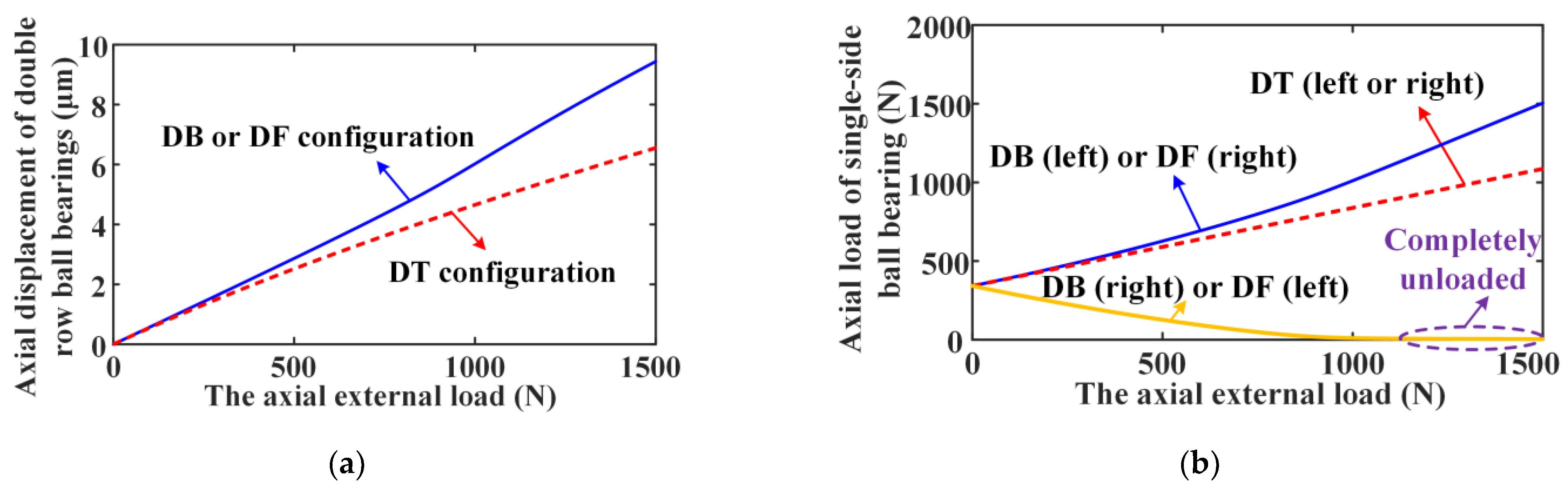
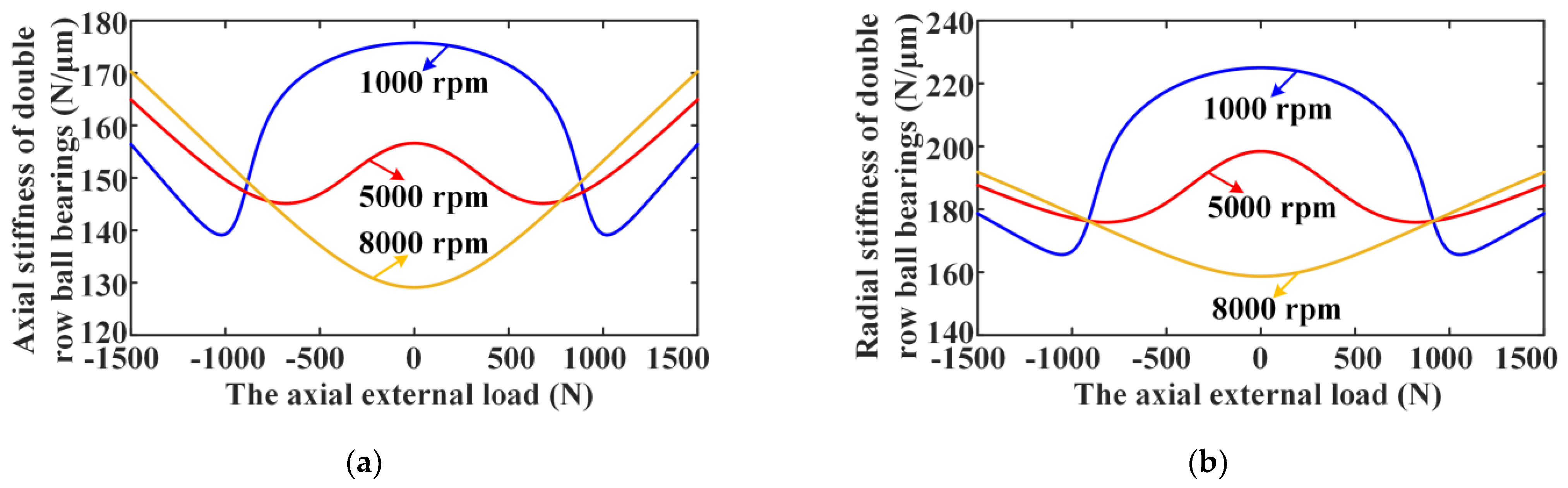
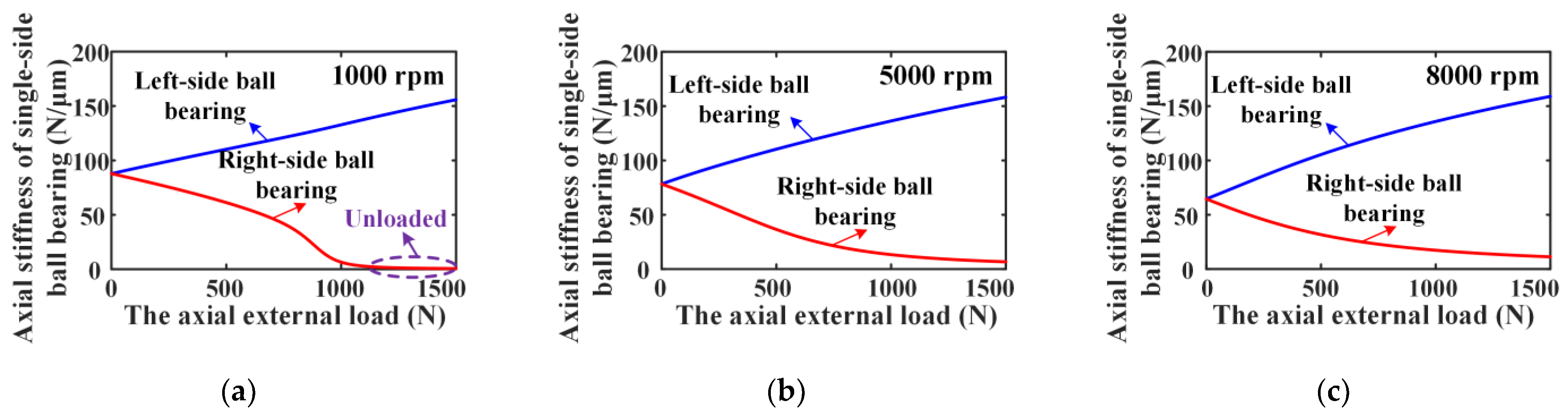
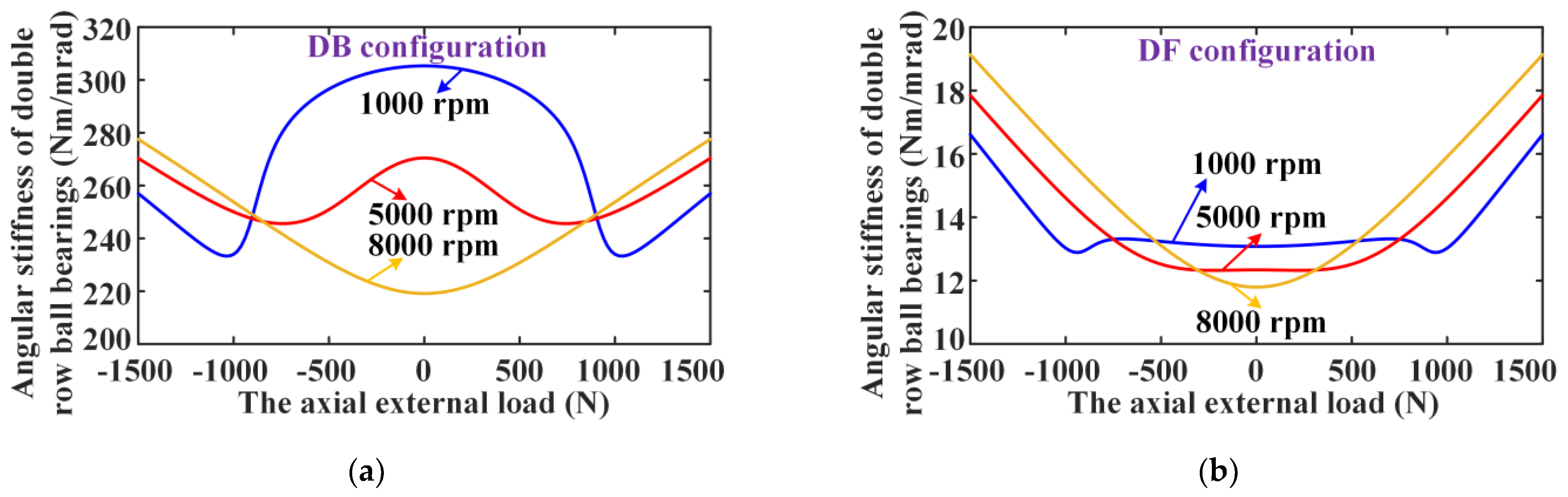
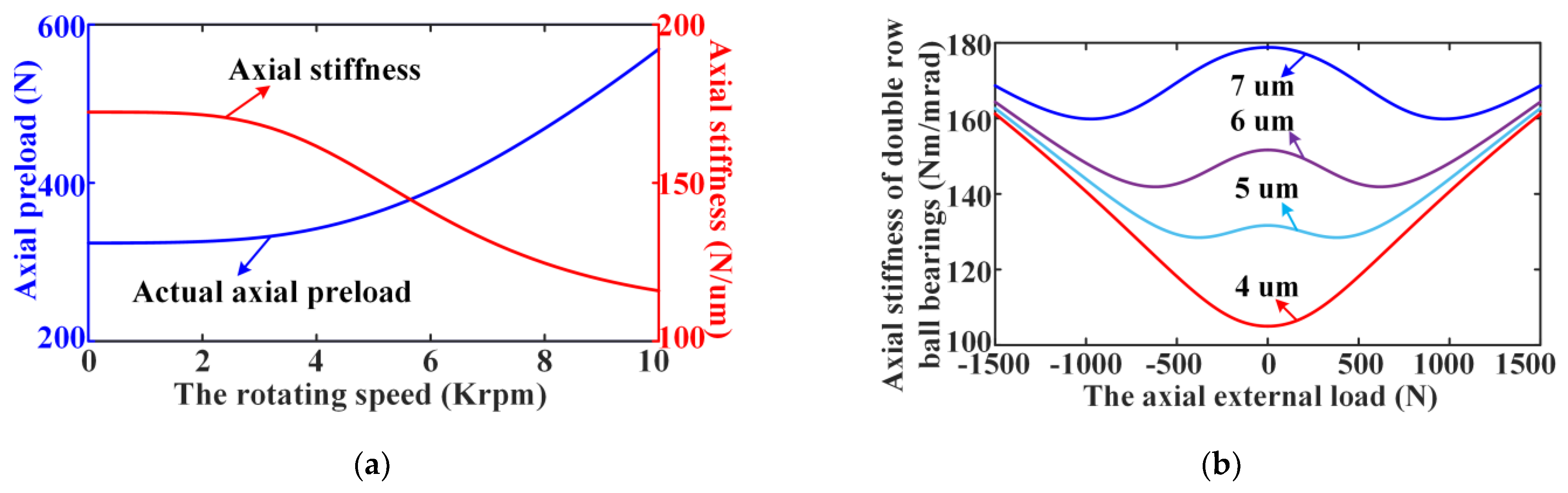
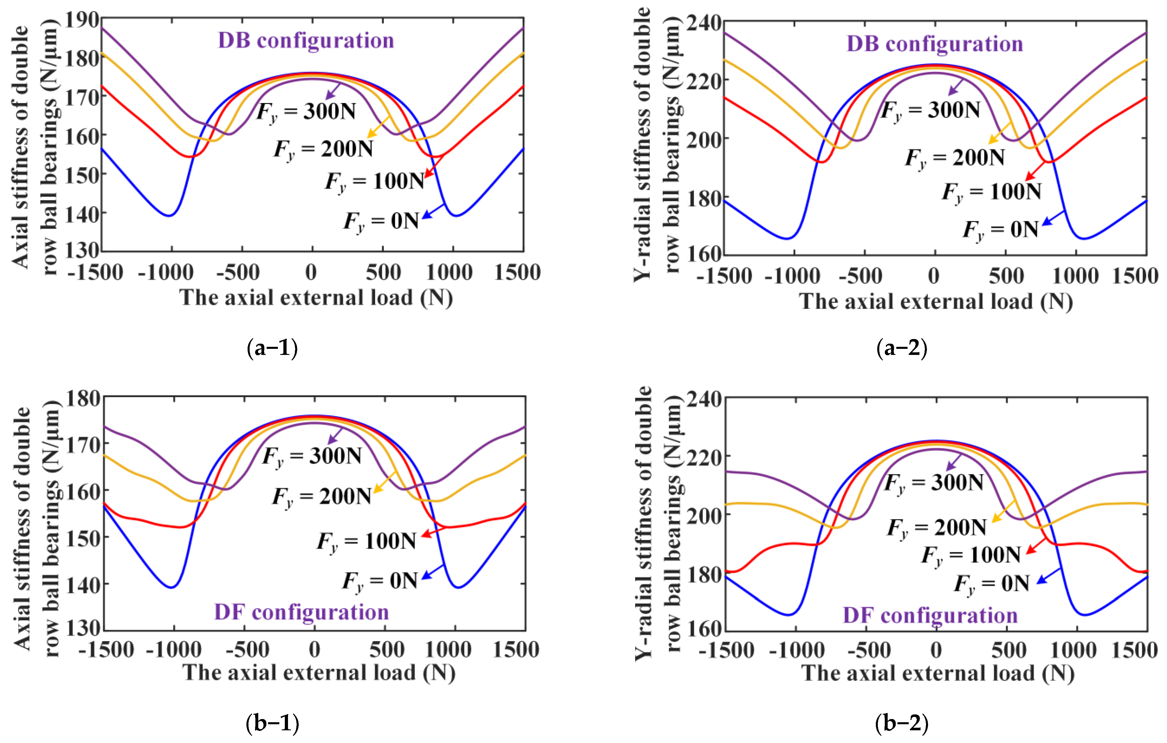
3.1. Analysis of Nonlinear Stiffness Characteristic of the Axially Loaded DR-ACBB

At first, as shown in Figure 6, the variation curves of the axial ring displacements and axial load distributions with the axial external load for DR-ACBB in three different configurations are presented. One can find that, due to the symmetry of the structure for DR-ACBB in DB and DF configurations, they have the same change curve, and similar phenomena also occur for DR-ACBB under pure radial load conditions in the subsequent analysis, while DR-ACBB under a DT configuration have better unidirectional load carrying capacities (i.e., the deformation under the same load is smaller). furthermore, by further observing Figure 6b, with the increase in the axial load, two SR-ACBBs inside DR-ACBBs under DB and DF configurations show different force states; that is, the axial restoring force generated by the left-side ACBB gradually increases, and the axial restoring force generated by the right-side ACBB decreases until it completely disappears. While for DR-ACBB under a DT configuration, since the installation direction of two SR-ACBBs is the same, the axial external force is evenly shared by two SR-ACBBs, so the stiffness and stiffness variation of DR-ACBB under a DT configuration satisfies the linear superposition principle. Therefore, the follow-up research in this paper is mainly aimed at a nonlinear stiffness characteristics analysis of DR-ACBBs under DB and DF configurations. In fact, DR-ACBB under a DT configuration cannot be used alone because the axial restoring force generated by the initial preload cannot be balanced without the external load.
Then, the influence of rotating speeds on the axial and radial stiffness variation rules versus axial load for DR-ACBBs under DB and DF configurations are shown in Figure 7 (i.e., DR-ACBBs under DB and DF configurations show the same stiffness variation curves). It can be found that when DR-ACBB operated at a low-speed range (i.e., 1000 rpm), both the axial and radial stiffness of DR-ACBB show a similar two-stage variation characteristics; that is, the bearing stiffness decreases in the light load range and increases in the heavy load range, which indicates that DR-ACBBs under DB and DF configurations show the nonlinear spring characteristics of soft first and then hard with the increase in axial load. By further observing Figure 8a, the dividing point of the above two-stage stiffness change curves for DR-ACBB at 1000 rpm is approximately located at the complete unloaded point of the right-side ACBB. Furthermore, as the rotating speed increases to 5000 and 8000 rpm, the axial external load range corresponding to stiffness attenuation gradually decreases until it disappears; at the same time, the phenomenon of the completely unloaded single-side ACBB is also not found, as shown in Figure 8b,c. In summary, DR-ACBB under DB and DF configurations show nonlinear soft-spring stiffness characteristics at a low-speed range and light (axial) load condition, while they show a nonlinear hard spring stiffness characteristic at relatively high-speed ranges or heavy (axial) load condition.
In addition, the comparison results of the angular stiffness versus axial external load of DR-ACBBs under DB and DF configurations are presented in Figure 9. One can find that the DR-ACBB under a DB configuration have a bigger angular stiffness and show a similar varying tendency to radial stiffness, while for DR-ACBB under a DF configuration, the bending moment resistance is poor due to the small angular stiffness, and the change trend of angular stiffness in its attenuation range is gentler.
Lastly, the influences of rotating speed on axial stiffness and the actual preload of DR-ACBB without external load are presented in Figure 10a. One can find that although the actual preload increases with rotating speed due to the action of ball centrifugal forces and the fixed-position preload mechanism [33], the axial stiffness of DR-ACBB still shows a significant attenuation tendency with rotating speed. Furthermore, it can be seen from Figure 10b that the initial preload plays a key role on the nonlinear stiffness variations of DR-ACBB. One can find that, increasing the preload can not only improve the overall stiffness of DR-ACBB but also expand the axial load range corresponding to the stiffness attenuation. Furthermore, the influence strength of initial preload decreases obviously at the large axial load condition, and the stiffness of DR-ACBB is mainly determined by the external load at this time.

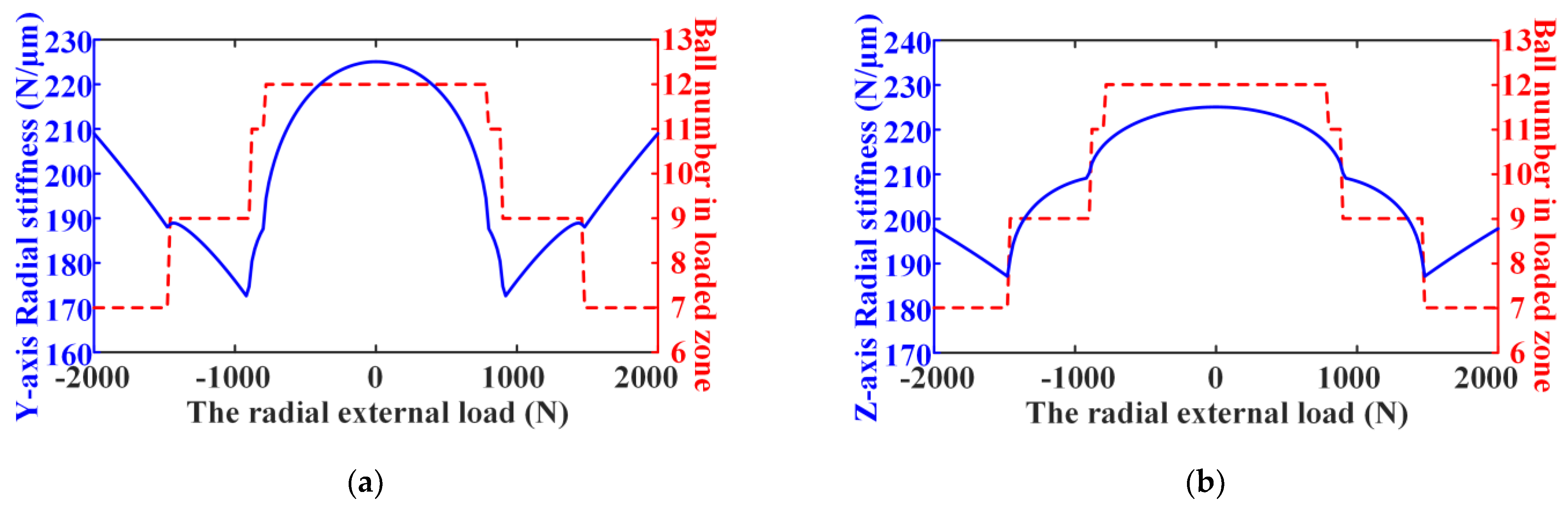
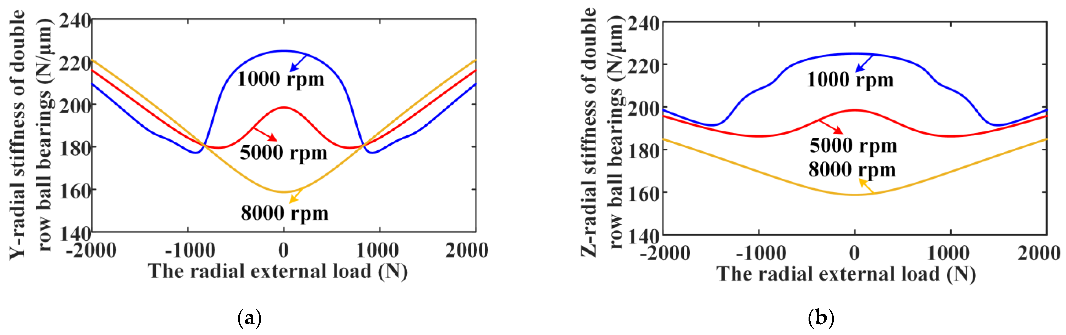
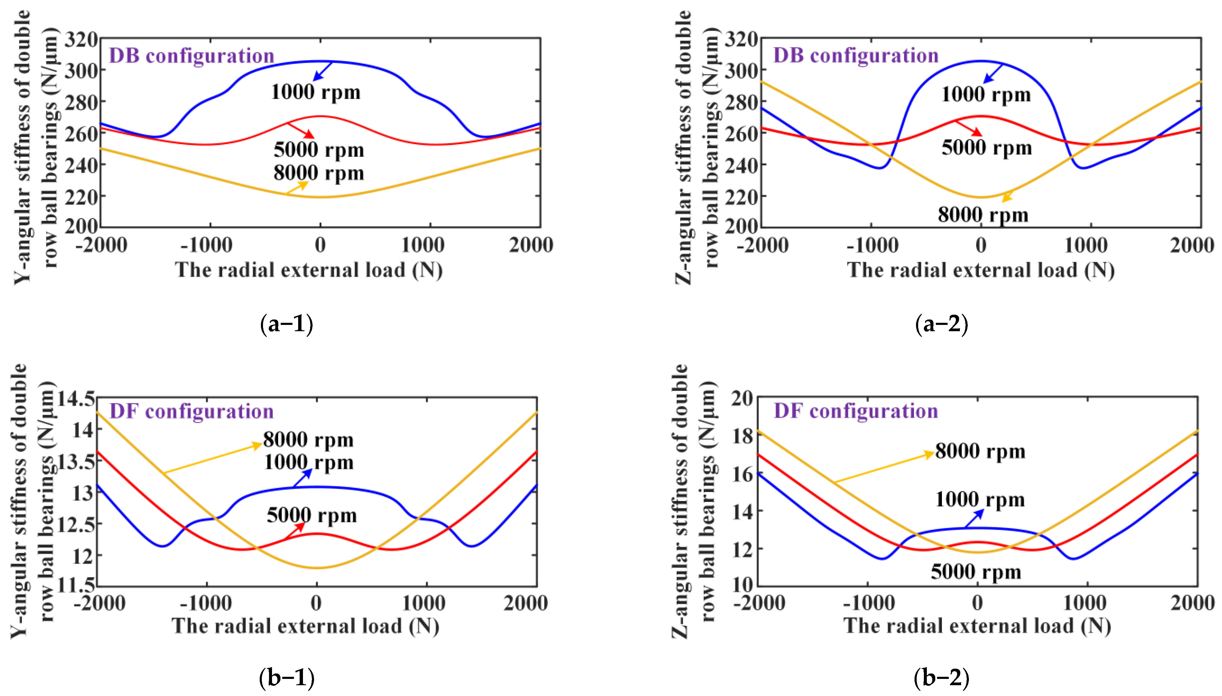
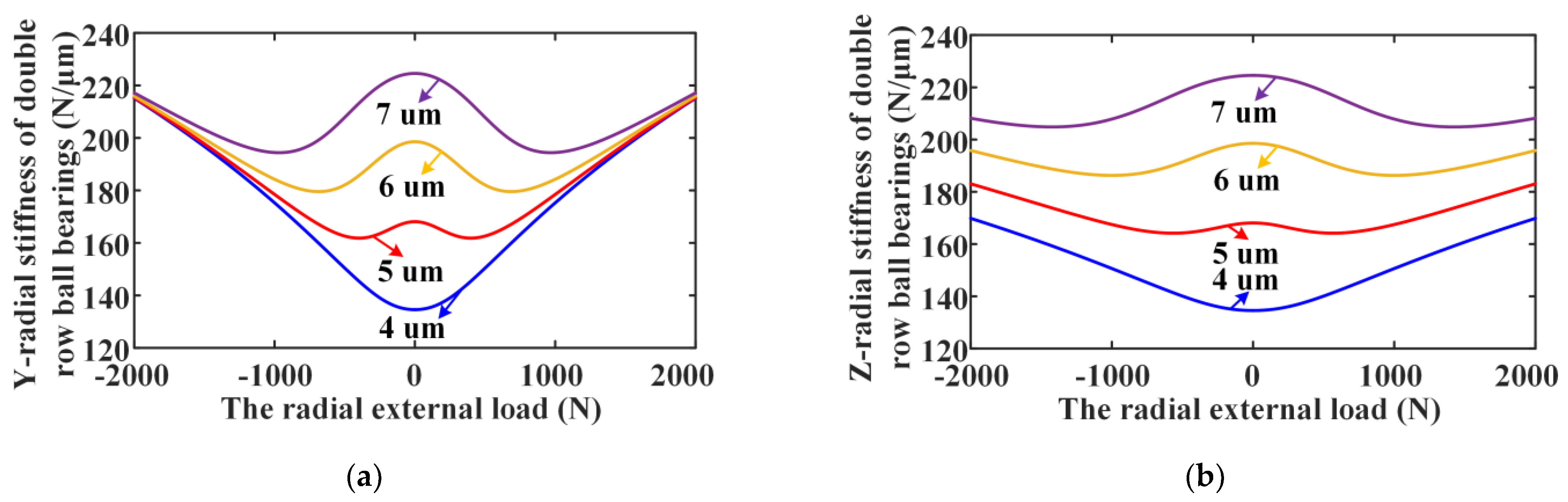
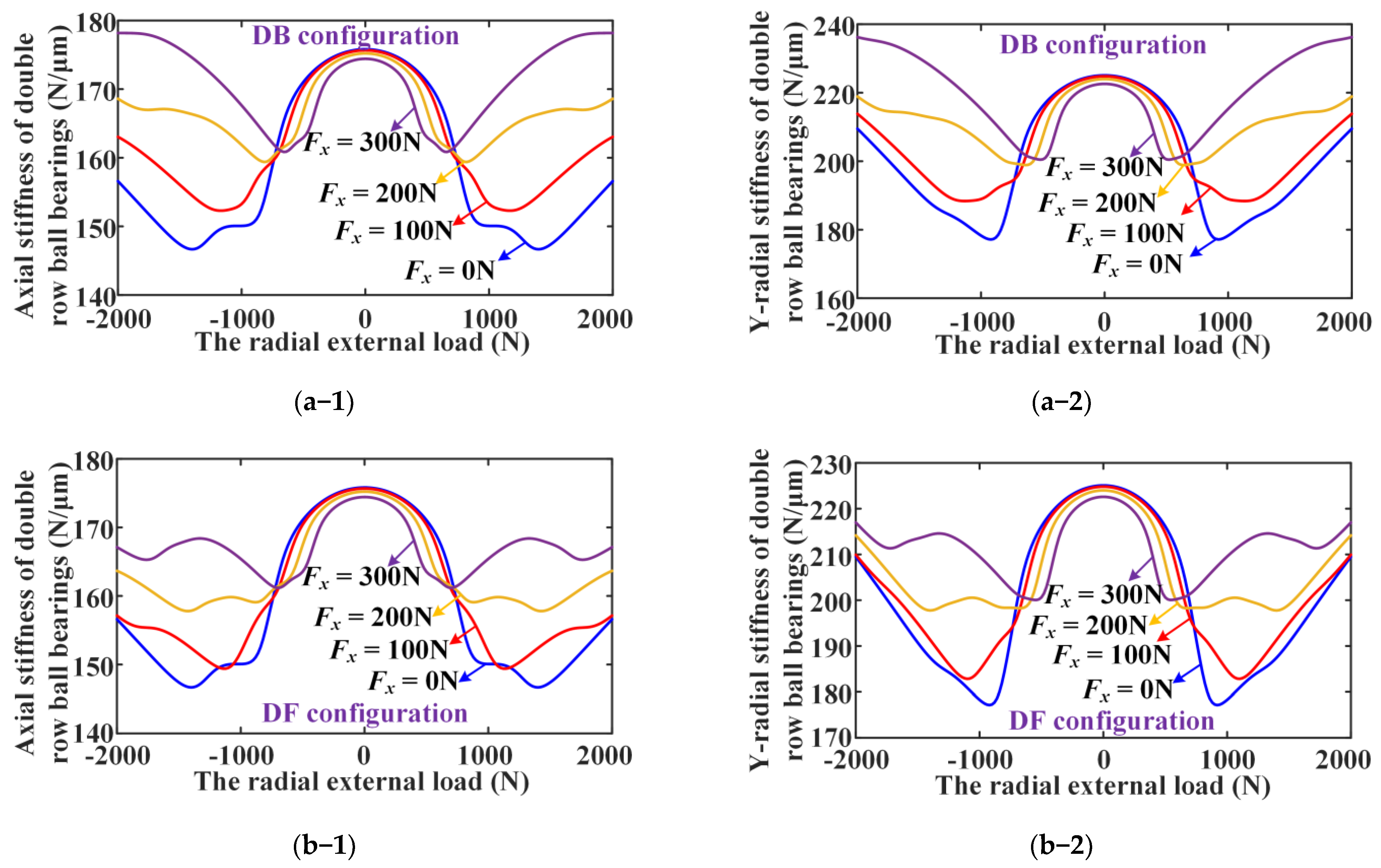
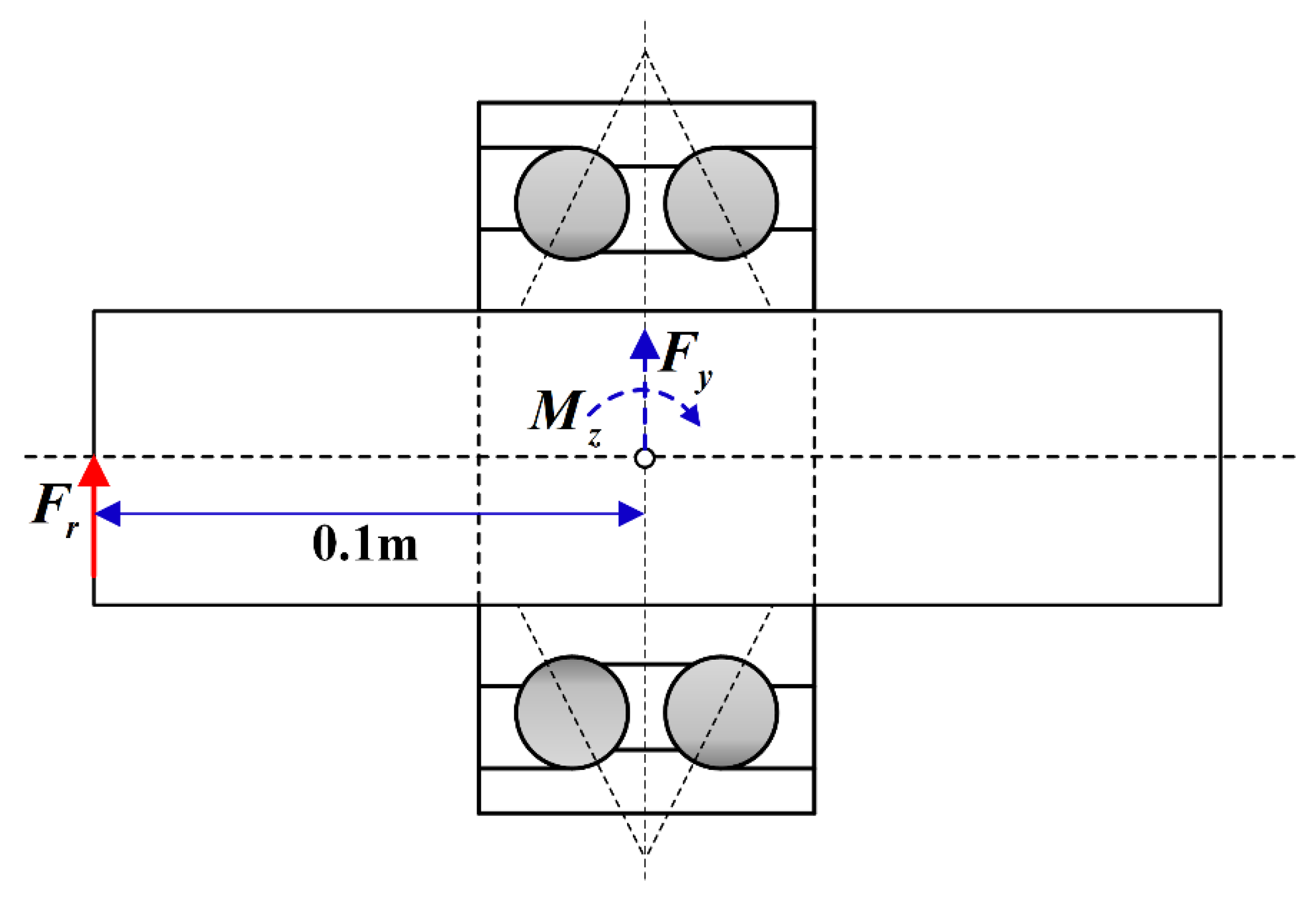
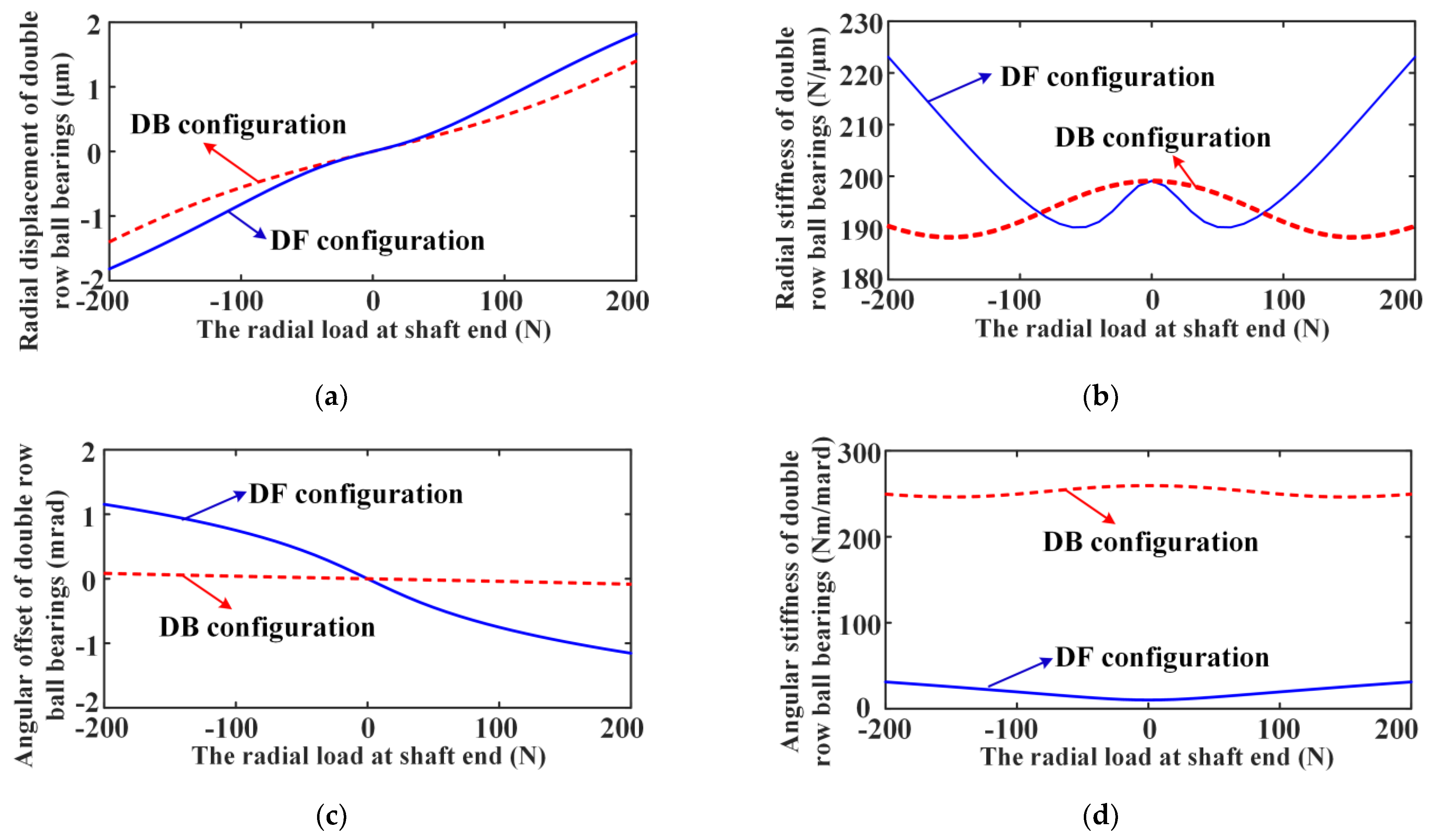
3.2. Analysis of Nonlinear Stiffness Characteristic of the Radially Loaded DR-ACBB

In this section, the nonlinear stiffness characteristics of DR-ACBB subjected to the radial load will be detailed, discussed, and analyzed.
First, as shown in Figure 11, the variation curves of the radial stiffness along the Y-axis and Z-axis versus the external load along the Y-axis for DR-ACBB under DB and DF configurations at static conditions are given (i.e., DR-ACBBs under DB and DF configurations still have the same radial stiffness variation rules). Similar to the nonlinear stiffness variation of the axially loaded DR-ACBB, the stiffness varying with radial load shows a multi-stage variation characteristic, and DR-ACBB also show the nonlinear spring characteristics of soft first and then hard with the increase in radial load. Furthermore, the changing rules of the ball number in the loaded area for SR-ACBB are also given in Figure 11. One can find that some of the rolling balls are unloaded under the action of a large radial load, which has an important impact on the size and variation trend of the stiffness of DR-ACBB.
On this basis, Figure 12 gives the influence rules of the rotating speed on the radial stiffness versus the radial load for DR-ACBB under DB or DF configurations. One can find that the stiffness variation trends of DR-ACBB in two different radial directions are slightly different; however, on the whole, they still show the following law: DR-ACBB under DB and DF configurations present a nonlinear soft-spring stiffness characteristic of a low-speed range and light (radial) load condition, while they show a nonlinear hard spring stiffness characteristic at a high-speed range or heavy (radial) load condition.
In addition, the comparison results of the angular stiffness versus radial external load of DR-ACBBs under DB and DF configurations are presented in Figure 13. One can find that DR-ACBB under a DB configuration still have a bigger angular stiffness and show a similar varying tendency to radial stiffness, while the angular stiffness of DR-ACBB under a DF configuration is relatively small, showing a gentle change trend in its attenuation range.
Lastly, the influences of the initial preload on the radial stiffness variations versus radial load of DR-ACBB are given in Figure 14. One can find that increasing the preload can also improve the overall stiffness and expand the radial load range corresponding to the stiffness attenuation of DR-ACBB. Similar to the axial-loaded condition, the influence strength of the initial preload also decreases obviously at the large radial load condition, and the stiffness of DR-ACBB is mainly determined by the external load at this time.

3.3. Analysis of Nonlinear Stiffness Characteristic of the Combined-Loaded DR-ACBB

As shown in Figure 15, the nonlinear stiffness variation curves for DR-ACBB subjected to constant radial loads (i.e., 0 N, 100 N, 200 N, 300 N) and varying axial loads are presented. It can be found that both DR-ACBBs under DB and DF configurations show the nonlinear spring characteristics of soft first and then hard with axial load, and the axial load ranges corresponding to the stiffness softening decrease with constant radial load. Furthermore, compared to DR-ACBB under a DB configuration, nonlinear stiffness variation curves versus the axial loads of DR-ACBB under a DF configuration are more complex and show obvious multi-stage change trends under a large load range.
Then, the nonlinear stiffness variation curves for DR-ACBB subjected to constant axial loads (i.e., 0 N, 100 N, 200 N, 300 N) and varying radial loads are presented in Figure 16. It can be found that both DR-ACBBs under DB and DF configurations show the nonlinear spring characteristics of soft first and then hard with axial load, and the axial load ranges corresponding to the stiffness softening decrease with constant axial load.
At last, we accurately simulate the actual bearing load conditions and illustrate the difference of the nonlinear stiffness characteristics of DR-ACBBs under DB and DF configuration. As shown in Figure 17, we assume that a rigid rotor system supported by DR-ACBB is subjected to radial load at the shaft end, and then the change curves of the radial and angular displacements and stiffness of DR-ACBB are calculated and presented in Figure 18. One can find that the radial and angular displacements of DR-ACBB under a DB configuration are less than those of DR-ACBB under a DF configuration, and the radial stiffness of DR-ACBBs under both DB and DF configurations shows a nonlinear soft spring stiffness characteristic under the light load range, while showing a nonlinear hard spring stiffness characteristic under the heavy load range, and the DB configuration shows a larger load range corresponding to the bearing stiffness attenuation. Furthermore, the angular stiffness of DR-ACBBs under two different configurations slightly fluctuates with radial external load, and the angular stiffness of DR-ACBB under DB configuration is far larger than that of DR-ACBB under a DF configuration. In summary, DR-ACBB under a DB configuration have better radial bearing capacity due to their large angular stiffness.

4. Conclusions

In this paper, based on the improved quasi-static model of SR-ACBB, a general model is proposed to calculate and analyze the complex nonlinear stiffness characteristics of DR-ACBB under different arrangements, and the influences of the rotating speed, preload, and external force on the nonlinear stiffness characteristics of DR-ACBB under different arrangements are comparatively analyzed. This paper provides a theoretical foundation for the modeling and nonlinear dynamic analysis of the complex rotor-bearing system. Based on the above studies, the following conclusions are given:
(1)
DR-ACBBs under DB and DF configurations have the same variation rule in axial and radial stiffness, and DR-ACBBs under DB and DF configurations show the nonlinear spring characteristics of soft first and then hard with the increase in external load;
(2)
The SR-ACBB or part of the balls may be unloaded for DR-ACBB under the large load ranges, which further leads to the sudden change in the nonlinear stiffness characteristics of DR-ACBB;
(3)
The initial preload has a great influence on the nonlinear stiffness characteristics of DR-ACBB, and it can effectively increase the external load range corresponding to the stiffness attenuation of DR-ACBB;
(4)
DR-ACBB under a DB configuration have higher angular stiffness and bending moment resistance than those of DR-ACBB under a DF configuration.

Author Contributions

Conceptualization and methodology, B.F. and J.Z.; software, B.F.; formal analysis, K.Y.; investigation, J.H.; writing—original draft preparation, B.F.; writing—review and editing: J.Z., K.Y. and J.H. All authors have read and agreed to the published version of the manuscript.

Funding

This research was supported by the National Key R&D Program of China (Grant No. 2021YFB2011000), National Natural Science Foundation of China under Grant (No. 52205281), China Postdoctoral Science Foundation (Grant No. 2021M62551), and two-chain fusion high-end machine tool projects of Shaanxi Province under Grant (2021LLRh-01-02).

Data Availability Statement

Not applicable.

Conflicts of Interest

The authors declare no conflict of interest.

References

  1. Bercea, I.; Nelias, D.; Cavallaro, G. A unified and simplified treatment of the non-linear equilibrium problem of double-row rolling bearings. Part 1: Rolling bearing model. Proc. Inst. Mech. Eng. Part J.-J. Eng. Tribol. 2003, 217, 205–212. [Google Scholar] [CrossRef]
  2. Gunduz, A.; Singh, R. Stiffness matrix formulation for double row angular contact ball bearings: Analytical development and validation. J. Sound Vib. 2013, 332, 5898–5916. [Google Scholar] [CrossRef]
  3. Gunduz, A.; Dreyer, J.T.; Singh, R. Effect of bearing preloads on the modal characteristics of a shaft-bearing assembly: Experiments on double row angular contact ball bearings. Mech. Syst. Signal. Pr. 2012, 31, 176–195. [Google Scholar] [CrossRef]
  4. Petersen, D.; Howard, C.; Prime, Z. Varying stiffness and load distributions in defective ball bearings: Analytical formulation and application to defect size estimation. J. Sound Vib. 2015, 337, 284–300. [Google Scholar] [CrossRef]
  5. Xu, T.; Yang, L.; Wu, W.; Wang, K. Effect of angular misalignment of inner ring on the contact characteristics and stiffness coefficients of duplex angular contact ball bearings. Mech. Mach. Theory. 2021, 157, 104178. [Google Scholar] [CrossRef]
  6. Poplawski, J.V.; Maureillo, J.A. Skidding in Lightly Loaded High Speed Ball Thrust Bearings; ASME: New York, NY, USA, 1969. [Google Scholar]
  7. Harris, T.A. An analytical method to predict skidding in thrust-loaded, angular-contact ball bearings. J. Lubr. Technol. 1971, 93, 17–23. [Google Scholar] [CrossRef]
  8. Harris, T.A. Ball motion in thrust-loaded, angular contact bearings with Coulomb friction. J. Lubr. Technol. 1971, 93, 32–38. [Google Scholar] [CrossRef]
  9. Harris, T.A. Rolling Bearing Analysis, 4th ed.; John Wiley and Sons, Inc.: New York, NY, USA, 2000. [Google Scholar]
  10. Ding, C.A.; Zhou, F.Z.; Zhu, J.; Zhang, L. Raceway control assumption and the determination of rolling element attitude angle. Chin. J. Mech. Eng. 2001, 37, 58–61. [Google Scholar] [CrossRef]
  11. Tomović, R. Calculation of the boundary values of rolling bearing deflection in relation to the number of active rolling elements. Mech. Mach. Theory. 2012, 47, 74–88. [Google Scholar] [CrossRef]
  12. Tomović, R. Calculation of the necessary level of external radial load for inner ring support on q, rolling elements in a radial bearing with internal radial clearance. Int. J. Mech. Sci. 2012, 60, 23–33. [Google Scholar] [CrossRef]
  13. Wang, W.Z.; Hu, L.; Zhang, S.G.; Zhao, Z.Q.; Ai, S.Y. Modeling angular contact ball bearing without raceway control hypothesis. Mech. Mach. Theory. 2014, 82, 154–172. [Google Scholar] [CrossRef]
  14. Yan, K.; Wang, Y.; Zhu, Y.; Hong, J.; Zhai, Q. Investigation on Heat Dissipation Characteristic of Ball Bearing Cage and Inside Cavity at Ultra High Rotation Speed. Tribol. Int. 2016, 93, 470–481. [Google Scholar] [CrossRef]
  15. Yang, Z.; Yu, T.; Zhang, Y.; Sun, Z. Influence of Cage Clearance on the Heating Characteristics of High-Speed Ball Bearings. Tribol. Int. 2017, 105, 125–134. [Google Scholar] [CrossRef]
  16. Ren, X.; Zhai, J.; Ren, G. Calculation of radial load distribution on ball and roller bearings with positive, negative and zero clearance. Int. J. Mech. Sci. 2017, 131, 1–7. [Google Scholar]
  17. Liu, J.; Shao, Y. Dynamic modeling for rigid rotor bearing systems with a localized defect considering additional deformations at the sharp edges. J. Sound. Vib. 2017, 398, 84–102. [Google Scholar] [CrossRef]
  18. Liu, J. A dynamic modelling method of a rotor-roller bearing-housing system with a localized fault including the additional excitation zone. J. Sound. Vib. 2020, 469, 115144. [Google Scholar] [CrossRef]
  19. Gargiulo, E.P. A Simple Way to Estimate Bearing Stiffness. Mach. Des. 1980, 52, 107–110. [Google Scholar]
  20. Wardle, F.P.; Lacey, S.J.; Poon, S.Y. Dynamic and static characteristics of a wide speed range machine tool spindle. Precis. Eng. 1983, 5, 175–183. [Google Scholar] [CrossRef]
  21. Lim, C.T.; Singh, R. Vibration transmission through rolling element bearings, part I: Bearing stiffness formulation. J. Sound Vib. 1990, 139, 179–199. [Google Scholar] [CrossRef]
  22. Lim, C.T.; Singh, R. Vibration transmission through rolling element bearings, part II: System studies. J. Sound Vib. 1990, 139, 201–225. [Google Scholar] [CrossRef]
  23. Lim, C.T.; Singh, R. Vibration transmission through rolling element bearings, Part III: Geared rotor system studies. J. Sound Vib. 1991, 151, 31–54. [Google Scholar] [CrossRef]
  24. Houpert, L. A uniform analytical approach for ball and roller bearings calculations. J. Tribol. 1997, 119, 851–858. [Google Scholar] [CrossRef]
  25. Hernot, X.; Sartor, M.; Guillot, J. Calculation of the stiffness matrix of angular contact ball bearings by using the analytical approach. J. Mech. Des. 2000, 122, 83–90. [Google Scholar] [CrossRef]
  26. Sheng, X.; Li, B.; Wu, Z.; Li, H. Calculation of ball bearing speed-varying stiffness. Mech. Mach. Theory. 2014, 81, 166–180. [Google Scholar] [CrossRef]
  27. Noel, D.; Ritou, M. Complete analytical expression of the stiffness matrix of angular contact ball bearings. J. Tribol. 2013, 135, 041101. [Google Scholar] [CrossRef]
  28. Liu, J.; Tang, C.; Wu, H.; Xu, Z.; Wang, L. An analytical calculation method of the load distribution and stiffness of an angular contact ball bearing. Mech. Mach. Theory. 2019, 142, 103597. [Google Scholar] [CrossRef]
  29. While, M.F. Rolling element bearing vibration transfer characteristics: Effect of stiffness. J. Appl. Mech. 1979, 46, 677–684. [Google Scholar] [CrossRef]
  30. Yang, Z.H.; Li, B.T.; Yu, T.X. Influence of structural parameters and tolerance on stiffness of high-speed ball bearings. Int. J. Precis. Eng. Man. 2016, 17, 1493–1501. [Google Scholar] [CrossRef]
  31. Yang, Z.; Chen, H.; Yu, T. Effects of rolling bearing configuration on stiffness of machine tool spindle, P. I. Mech. Eng. C.-J. Mec. 2018, 232, 775–785. [Google Scholar] [CrossRef]
  32. Li, J.; Zhu, Y.; Yan, K.; Yan, X.; Liu, Y.; Hong, J. Research on the axial stiffness softening and hardening characteristics of machine tool spindle system. Int. J Adv. Manuf. Tech. 2018, 99, 951–963. [Google Scholar] [CrossRef]
  33. Zhang, J.; Fang, B.; Zhu, Y.; Hong, J. A comparative study and stiffness analysis of angular contact ball bearings under different preload mechanisms. Mech. Mach. Theory. 2017, 115, 1–17. [Google Scholar] [CrossRef]
  34. Zhang, J.; Fang, B.; Hong, J.; Wan, S.; Zhu, Y. A general model for preload calculation and stiffness analysis for combined angular contact ball bearings. J. Sound. Vib. 2017, 411, 435–449. [Google Scholar] [CrossRef]
  35. Fang, B.; Zhang, J.; Yan, K.; Hong, J.; Wang, M. A comprehensive study on the speed-varying stiffness of ball bearing under different load conditions. Mech. Mach. Theory 2019, 136, 1–13. [Google Scholar] [CrossRef]
Figure 1. Three configurations of DR-ACBB: (a) DB arrangement; (b) DF arrangement; (c) DT arrangement.
Lubricants 11 00044 g001
Figure 2. The coordinate systems and force state of DR-ACBB under DB arrangement: (a) the diagram of DR-ACBB; (b) the diagram of the single-side ACBB.
Lubricants 11 00044 g002
Figure 3. The force analysis of local ball for DR-ACBB under DB arrangement.
Lubricants 11 00044 g003
Figure 4. The geometric analysis of local ball of the left-side ball bearing for the double-row ball bearing in DB arrangement.
Lubricants 11 00044 g004
Figure 5. The detailed iterative calculation flow diagram for DR-ACBB.
Lubricants 11 00044 g005
Figure 6. The result curves of the axial displacements and load distributions versus the axial load for DR-ACBB under different configurations (N = 1000 rpm): (a) the axial displacement; (b) the axial load distribution.
Lubricants 11 00044 g006
Figure 7. The axial and radial stiffness variation curves versus the axial external load for DR-ACBB at three different speeds: (a) the axial stiffness; (b) the radial stiffness.
Lubricants 11 00044 g007
Figure 8. The change curves of the axial stiffness of two SR-ACBBs versus the axial external load for DR-ACBB under DB configuration: (a) rotating speed = 1000 rpm; (b) rotating speed = 5000 rpm; (c) rotating speed = 8000 rpm.
Lubricants 11 00044 g008
Figure 9. The comparison results of the angular stiffness versus axial external load of DR-ACBB under DB and DF configurations: (a) DB configuration; (b) DF configuration.
Lubricants 11 00044 g009
Figure 10. The effects of the speed and preload on the nonlinear stiffness variations of DR-ACBB: (a) the actual preload and axial stiffness varying with the speed; (b) the axial stiffness varying with axial load of DR-ACBB with different initial preloads (δp/2).
Lubricants 11 00044 g010
Figure 11. The results of the radial stiffness and ball number in loaded area versus radial load of DR-ACBB at static: (a) Y-axis radial stiffness; (b) Z-axis radial stiffness.
Lubricants 11 00044 g011
Figure 12. The results of the radial stiffness versus radial load for DR-ACBB under three different rotating speeds: (a) Y-axis radial stiffness; (b) Z-axis radial stiffness.
Lubricants 11 00044 g012
Figure 13. The comparison results of the angular stiffness versus radial load of DR-ACBB under DB and DF configurations: (a–1,a–2) DB configuration; (b–1,b–2) DF configuration.
Lubricants 11 00044 g013
Figure 14. The effects of the initial preload on the radial stiffness variations of DR-ACBB: (a) Y-axis radial stiffness; (b) Z-axis radial stiffness.
Lubricants 11 00044 g014
Figure 15. The results of the nonlinear stiffness variation for DR-ACBB subjected to constant radial loads and varying axial load (N = 1000 rpm): (a) axial stiffness; (b) radial stiffness.
Lubricants 11 00044 g015
Figure 16. The results of the nonlinear stiffness variation for DR-ACBB subjected to constant axial loads and varying radial load (N = 1000 rpm): (a) axial stiffness; (b) radial stiffness.
Lubricants 11 00044 g016
Figure 17. The schematic diagram of a rigid rotor system supported by the double-row ball bearing.
Lubricants 11 00044 g017
Figure 18. The radial and angular displacement and stiffness of double-row ball bearing in different configurations: (a) radial displacement; (b) radial stiffness; (c) angular offset; (d) angular stiffness.
Lubricants 11 00044 g018
Table 1. The key geometrical parameters of DR-ACBB 3210.
Parameters320
Curvature radius (inner-raceway) ri (mm)4.54
Curvature radius (outer-raceway) ro (mm)4.54
Contact diameter (inner-raceway) di (mm)61.22
Contact diameter (outer-raceway) do (mm)78.78
Ball number Z12
Ball diameter D (mm)8.73
Pitch diameter dm (mm)70
Preload displacement δ p (μm)12
Radial clearance (μm)100
The ball center distance (mm)15
Disclaimer/Publisher’s Note: The statements, opinions and data contained in all publications are solely those of the individual author(s) and contributor(s) and not of MDPI and/or the editor(s). MDPI and/or the editor(s) disclaim responsibility for any injury to people or property resulting from any ideas, methods, instructions or products referred to in the content.

