1. Introduction
The development of industrial applications using haptic feedback bilateral motion control is not only limited to purely physical human–machine interactions, but also includes virtual–cyber interactions in that visual, auditory, and tactile information can help to reinforce human operation. Visual and auditory information can be easily presented to the operator; however, it is difficult for the operator to feel the physical haptic feedback. Most of the human–machine interaction systems use vibration as the force/torque feedback, and not haptic feedback. It is known that haptic feedback can massively improve the experience of human–machine interaction, which is based on so-called bilateral motion control [
1,
2,
3]. The bilateral control system design has been widely used in cyber-physical applications, such as surgery [
4,
5] and driving simulators [
6,
7,
8].
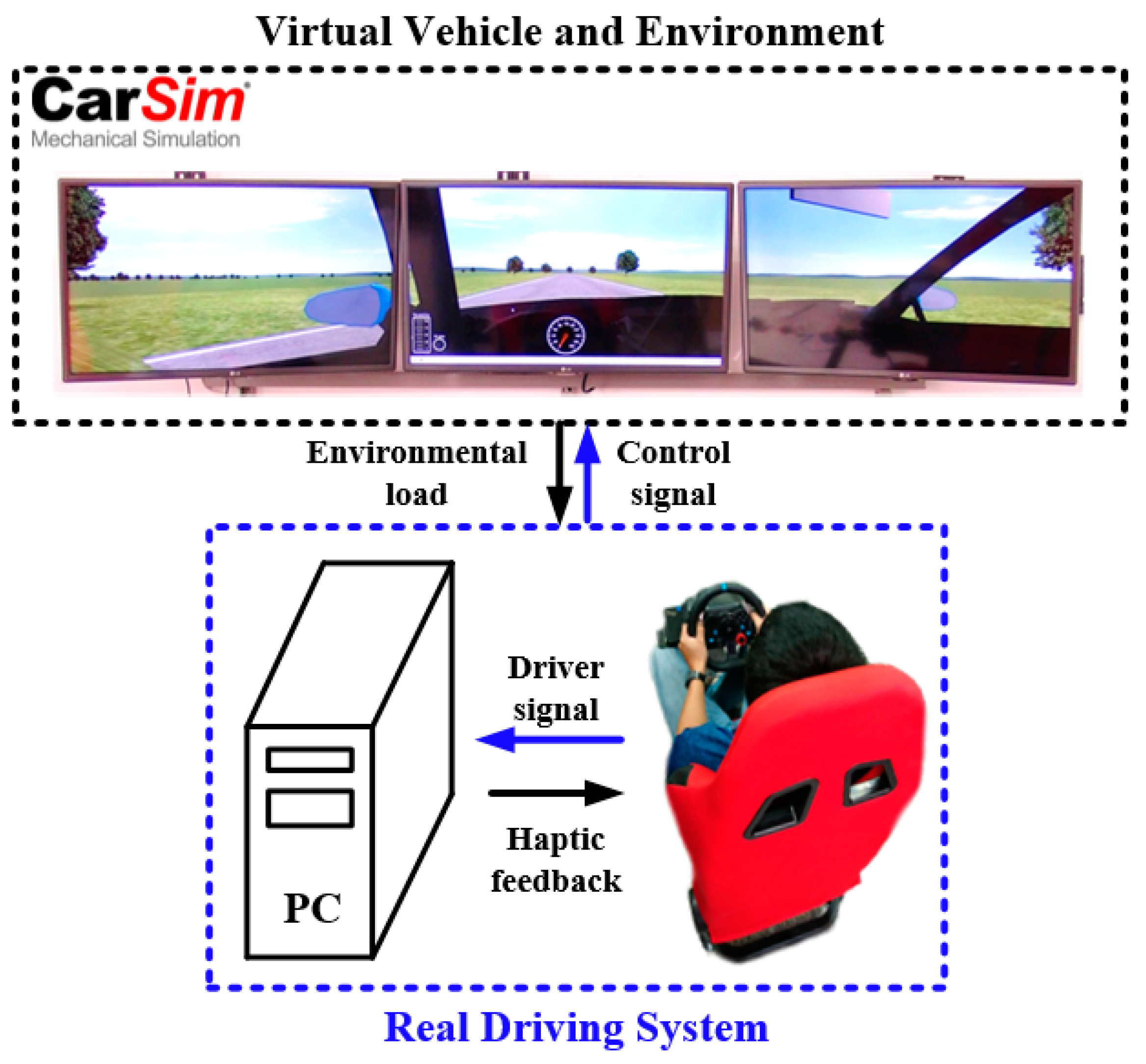
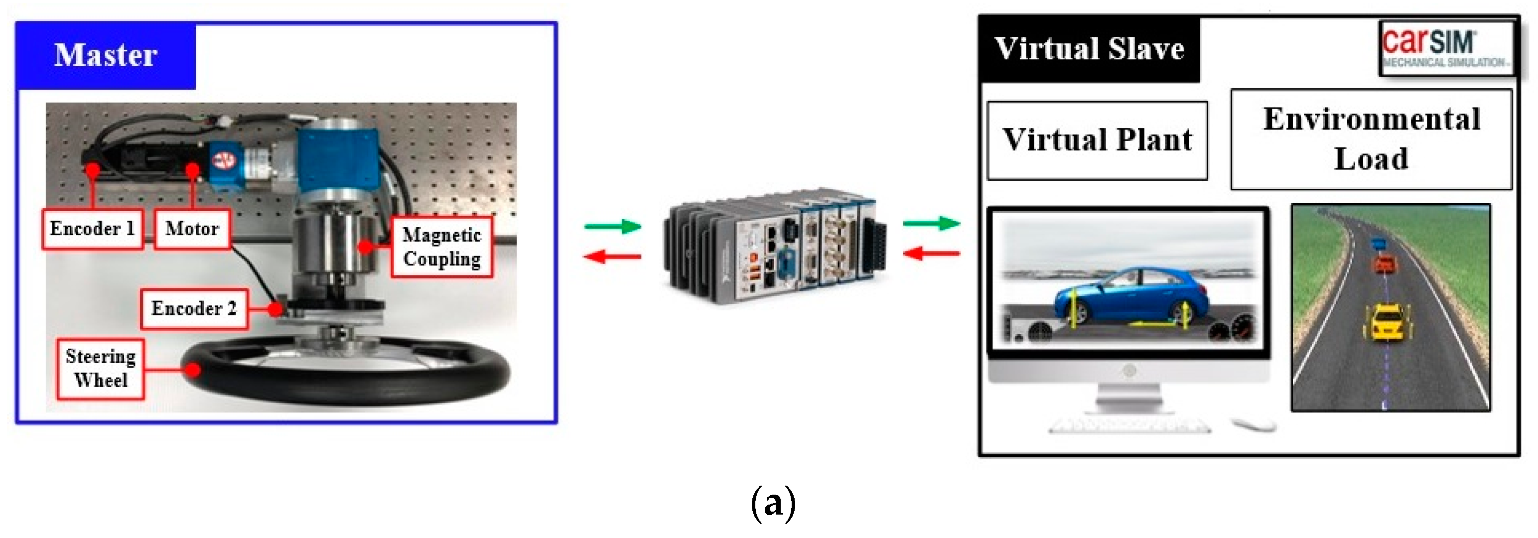
For driving simulator application that integrates vehicle dynamic simulation software such as CarSIM, the bilateral control system that enables human–machine and virtual–cyber interaction is made up of the steering mechanism called the master, and the virtual steering platform called the virtual slave. The main feature of a bilateral control system is the synchronous motion control whereby the virtual steering wheel has the same motion as the master. With the addition of pedals, the motion of a virtual car can be fully controlled by a human operator. The schematic setup of the driving simulator is depicted in
Figure 1 where the driving sensation of a real car, mimicked by the virtual car, is generated by CarSIM and transmitted to the master to reproduce a corresponding haptic feel.
Based on the bilateral control scheme of [
1], which directly utilizes the sum of external torques resulting from both master and slave sides and then feedforward to each control system, this study adopts the design of impedance control [
9] for which an impedance model is proposed to specify the haptic feedback tailored for the required environment.
However, an identified problem that should be addressed, is the influence of other disturbances not caused by the environmental forces but present at the slave side. Since actual mechanisms such as steering systems are coupled to a driving motor, model inaccuracy and unwanted disturbances that are inherently present in the bilateral control system, will adversely influence the tactile sensation of the operator [
10] and reduce the haptic transparency. These model inaccuracies and unwanted disturbances have been identified to emanate from the use of conventional torque sensors and mechanical coupling and links. Several solutions to improve haptic transparency performance have been presented, such as the use of torque sensors [
11] or the observer control method [
12,
13]. The observer presented in [
13] integrated a model-based disturbance compensation into the system to eliminate the negative effects of disturbances. The control performance of this method is highly dependent on the accuracy of an a priori known plant model.
Unlike the reviewed literature, this paper presents a different approach to bilateral control system, which combines the magnetic-coupler torque sensing with a disturbance observer for realizing haptic feedback. Moreover, the magnetic coupling as a component, does not only connect the steering wheel with the actuator, but also measures the relative position between the driver and driven sides. Unlike the commonly used mechanical flexible transmission mechanisms, such as torsion springs [
14,
15], magnetic coupling does not have any backlash [
16,
17], and its contactless characteristic can also provide inherent overload protection. As a result, the reaction torque responsible for reproducing haptic sensations to the operator can be detected and accurately measured by the magnetic coupling transmission module. Also, due to its frictionless and the elastic nature of its torsional stiffness, the magnetic coupling can provide a quick and smooth sensation of the reaction torque when operated within the admissible torque range. Furthermore, this paper presents an appropriate control scheme to deal with the disturbance feedforward compensation. The reaction torque measured from the magnetic coupling is used in the disturbance torque observer to decouple the load torque information. The model inaccuracy and external disturbances appearing on the driving motor installed in the master side can be adequately observed and then compensated. The feasibility and effectiveness of the proposed method for improving haptic transparency in virtual reality applications were verified using a cyber-physical CarSIM driving simulator experimental system.
2. Bilateral Control Structure
As technology advances, bilateral control is being applied in many fields, such as surgery [
18] and rehabilitation [
19]. To realize a haptic feedback bilateral control system [
20], the following two conditions should be satisfied:
where
τ and
θ denote the external torque and position of the motor, the subscripts
m and
v denote the master side and the virtual slave, respectively. Equation (1) shows that torque from each side needs to be balanced in the steady state. Then Equation (2) shows that for synchronization motion, the position control loops of both master and slave should follow the position command given by:
The bilateral control [
1] presented in this paper employed the feedforward control with specified reference model inertia. To provide the haptic feedback response setting, the impedance model approach employed at the speed-loop path is utilized as proposed in [
21].
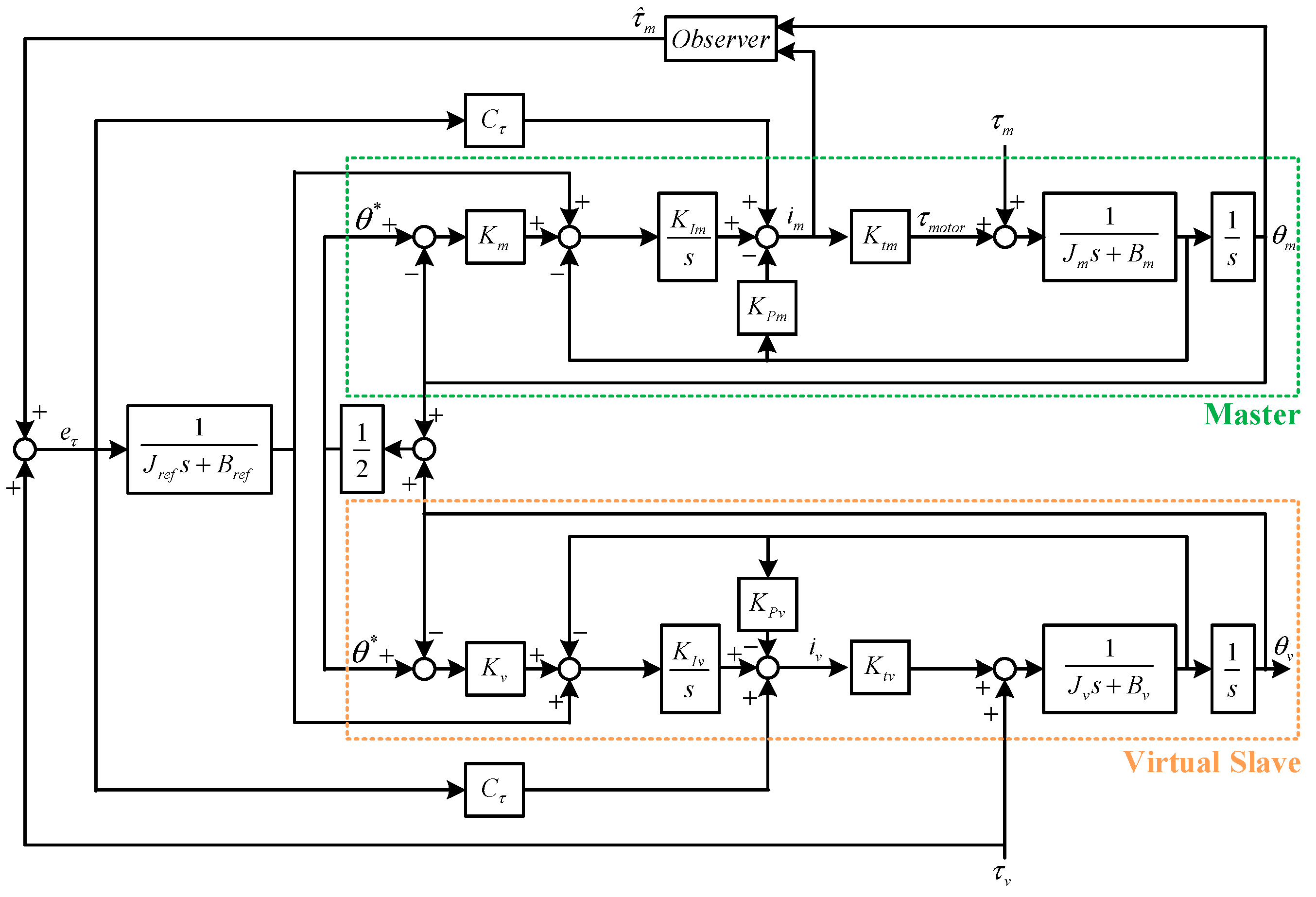
Figure 2 shows a bilateral motion control system, where
,
and
are the motor parameters: torque constant, equivalent rotor inertia and damping respectively. Furthermore,
is the proportional gain of the position-loop controller,
and
denote the parameters of the speed-loop controller,
is the torque-loop feedforward gain, and
,
are the parameters of a specified impedance model.
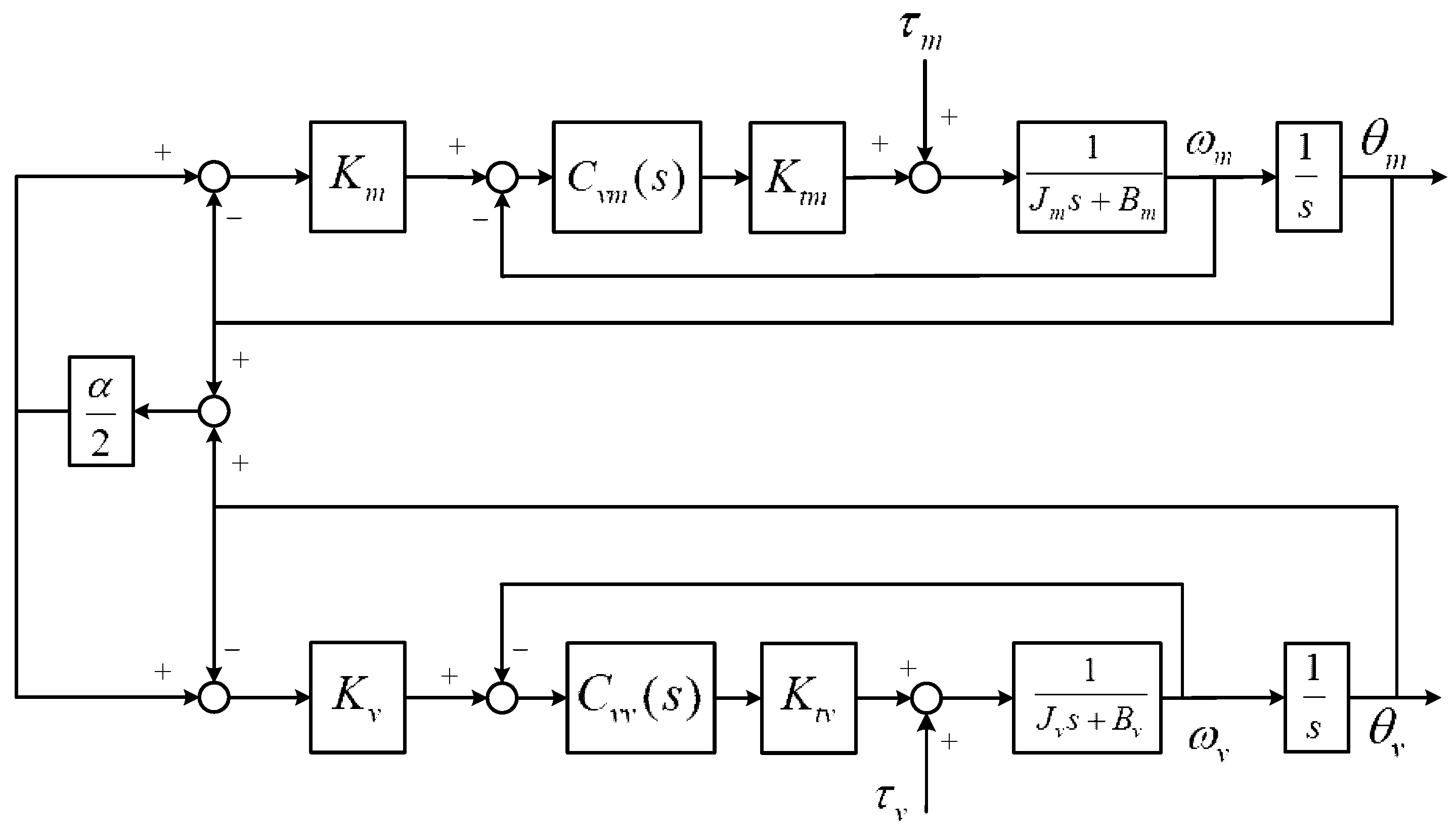
Synchronized motion control was presented in [
22] which investigated the characteristics of the control structure. To understand the synchronous property of the bilateral control system depicted in
Figure 2, let the feedforward reference model paths be removed as shown in
Figure 3. Here,
denote the velocity-loop controller, and the parameter
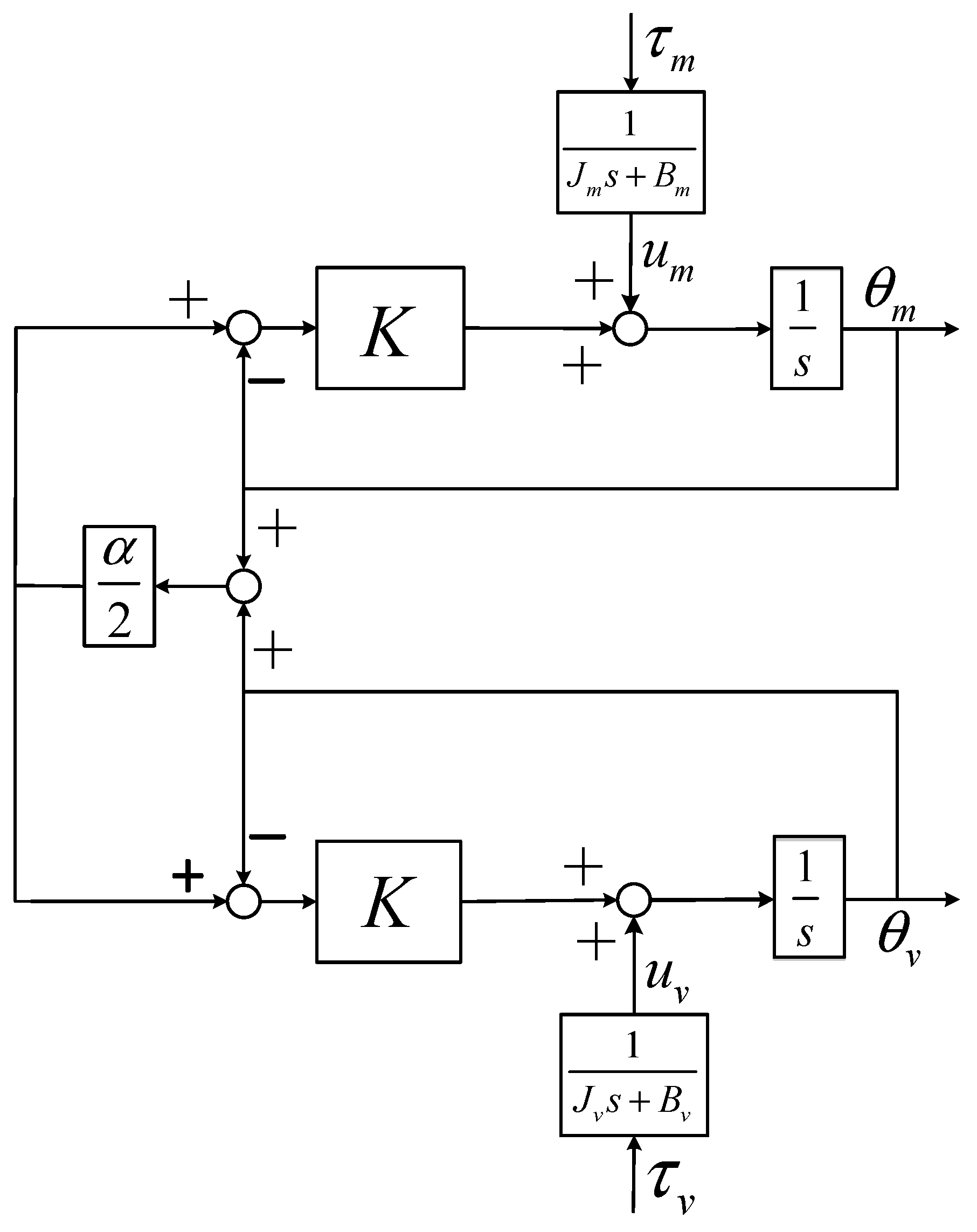
is regarded as the connecting bridge of the bilateral control system. Suppose that the position gains are the same, consider
(
K being the bandwidth of position loop), and that the bandwidth of the velocity loop is designed to be bigger than the position loop, then
Figure 3 can be illustrated as
Figure 4. When the input only comes from
, i.e., for the case of
(i.e.,
), we can obtain:
It can be found from Equations (4) and (5) that:
As can be seen from Equations (4) and (5) for the case of , the co-operated motion will be freely guided by the operator without difficulty. Obviously, when the torque input is from , responds quickly. At the steady state, Equation (6) shows that . Conversely, when the torque input is removed, response terminates. The artificial viscous factor can be employed to confirm the internal stability as needed.
3. Magnetic Coupling and Control Design Scheme
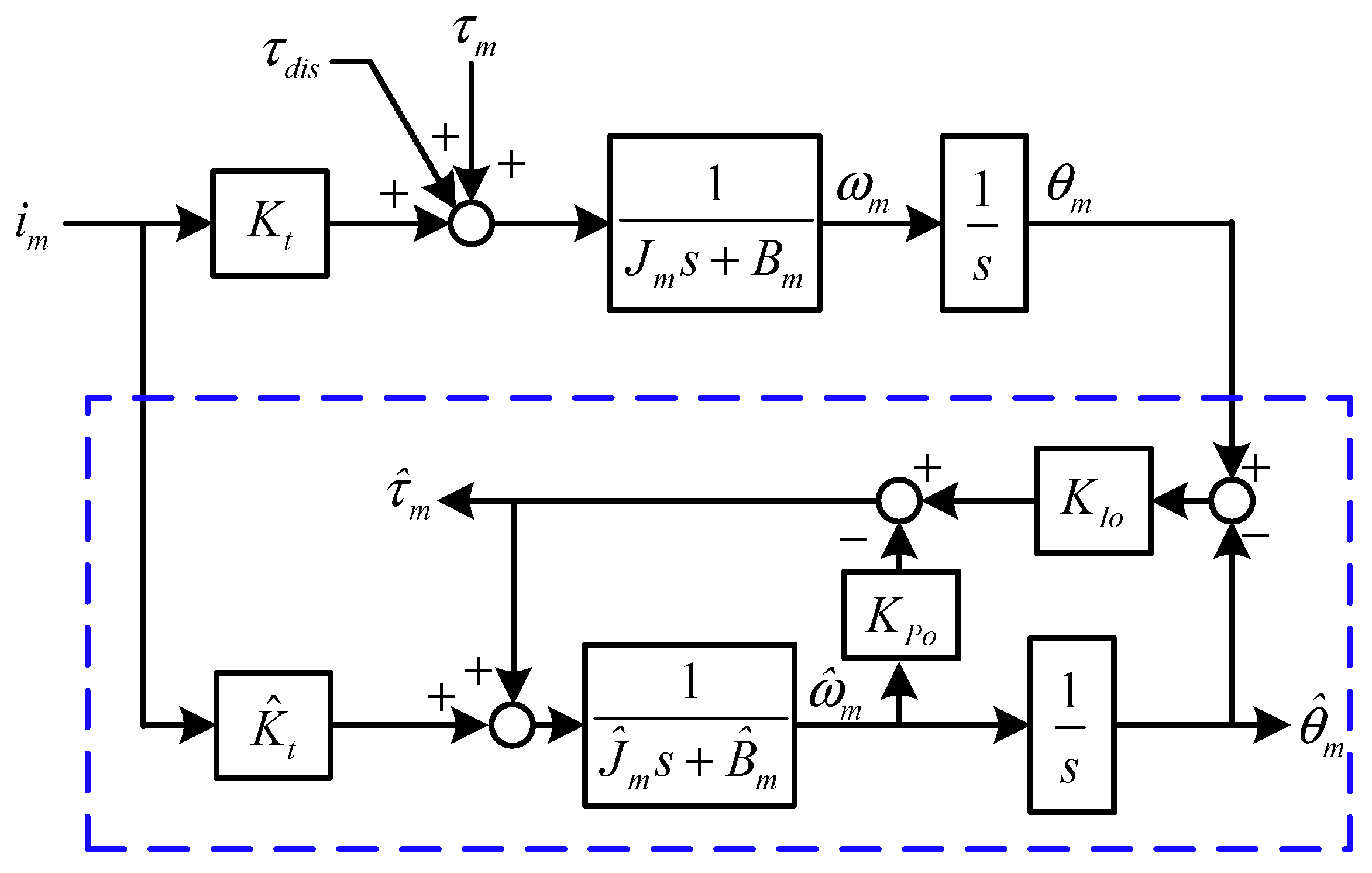
It is obvious that the effect of disturbances inherently appears when operating the steering mechanisms of the master side. The torque observer design can be employed to estimate the torque disturbance (i.e.,
+
) [
23,
24]. The observer for
required in
Figure 2 is shown in
Figure 5 where
and
denote the parameters of the observer compensator, and “^” denotes a nominal model of the controlled plant and the related estimated information.
From the torque disturbance observer shown in the blue dashed box of
Figure 5, it can be found that for the case without modeling error,
Obviously, the observed torque
at the steady state will contain not only the unwanted disturbances
such as uncertainties and parameter variation, but also the operator torque
, which reproduces haptic from external environmental load-torques applied to the slave. Since
within the tailored dynamic bandwidth, the torque observer cannot distinguish the operator and the disturbance torque, the integrity and accuracy of the haptic sensation is compromised, where only the operator torque is wanted. Torque sensing has been employed [
11] for improving haptic transparency performance. Torque measurements by relative displacement over a mechanical spring have been prevalent to the more-bulky and costly strain gage-based torque sensors. We propose a torque-measured magnetic coupling approach with a modified configuration of the torque observer to suppress the disturbances and create reaction torque that follows the physical or virtual torque generated by the slave side. The magnetic coupling can be packaged as part of the motor drive and has an additional feature of limiting the level of the transmitted torque, which is important for human safety.
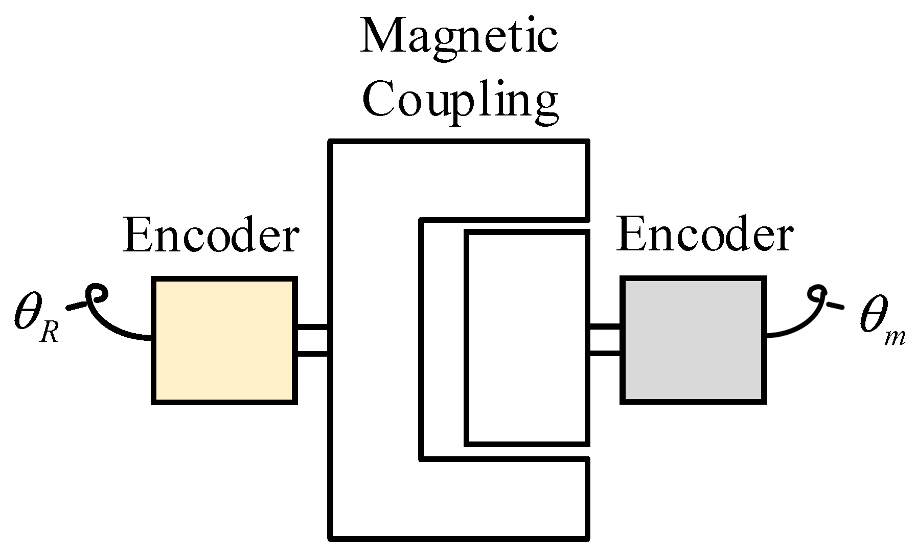
Magnetic coupling is a contactless and non-friction transmission mechanism that has a 1:1 gear ratio. Its contactless characteristic can be utilized in the steering system, such as [
15] to provide transmission and smooth sensation compared to mechanical rigid contact couplings. The magnetic coupling also provides the function of overload protection for the situation while the motor driving torque is over the required safety. Because of the finite stiffness characteristic, the transmission torque of magnetic coupling can be easily measured by optical encoders as shown in
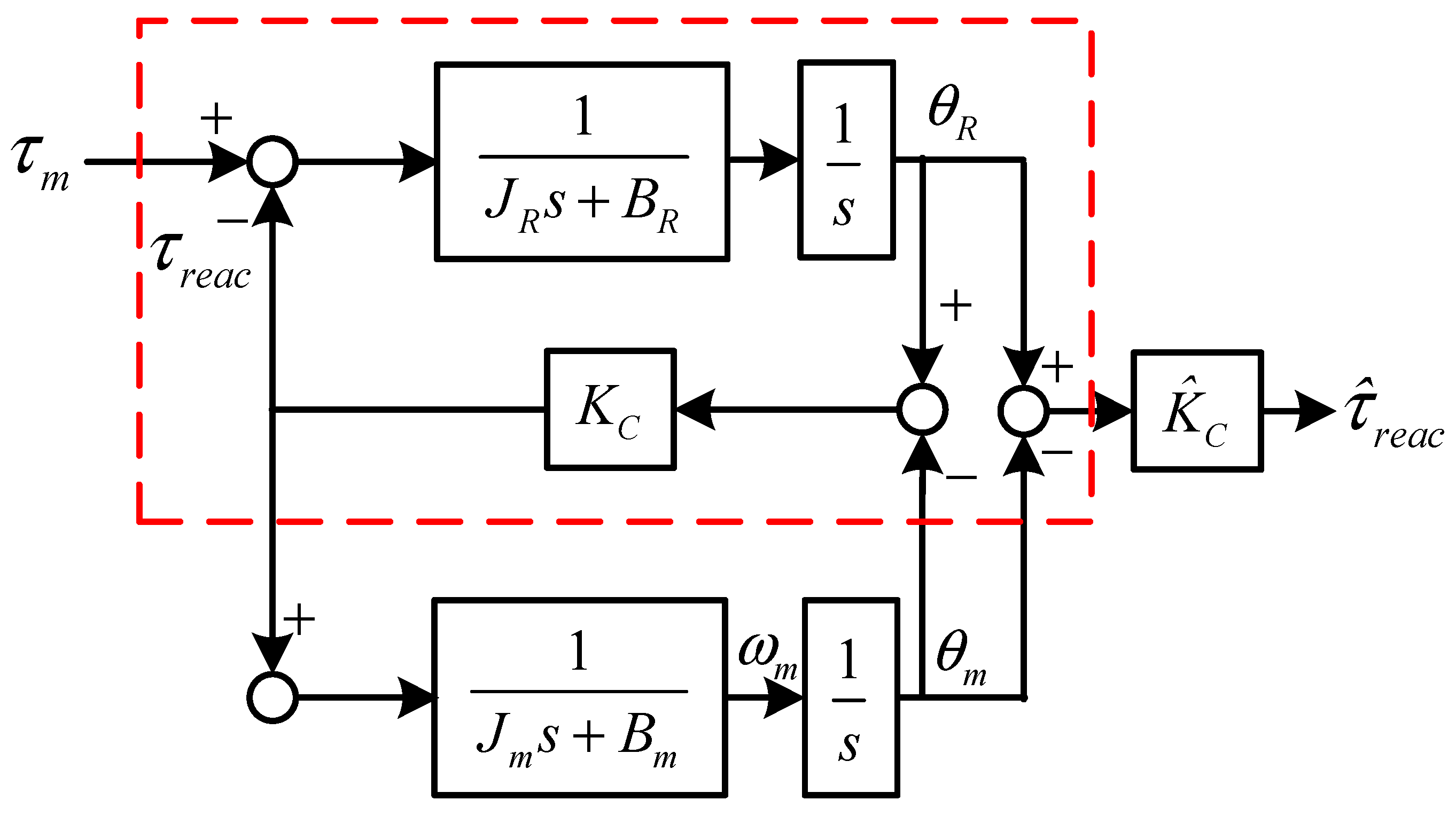
Figure 6. A block diagram of the proposed transmission module for torque measurement is presented in
Figure 7 where
denotes the operator torque, and
denotes the reaction torque reproducing haptic to the operator where
is the stiffness constant of the coupling. As
can be attained accurately using practical measurement, the coupling module is capable of detecting external reaction torque as follows:
Here, the magnetic coupling is employed to be a function as a torque sensor for measuring the external reaction torque from its position difference. Unlike the rough sensation experience due to the high stiffness of torque sensors, the magnetic coupling can provide much smoother sensation and comfort for the operator when steering.
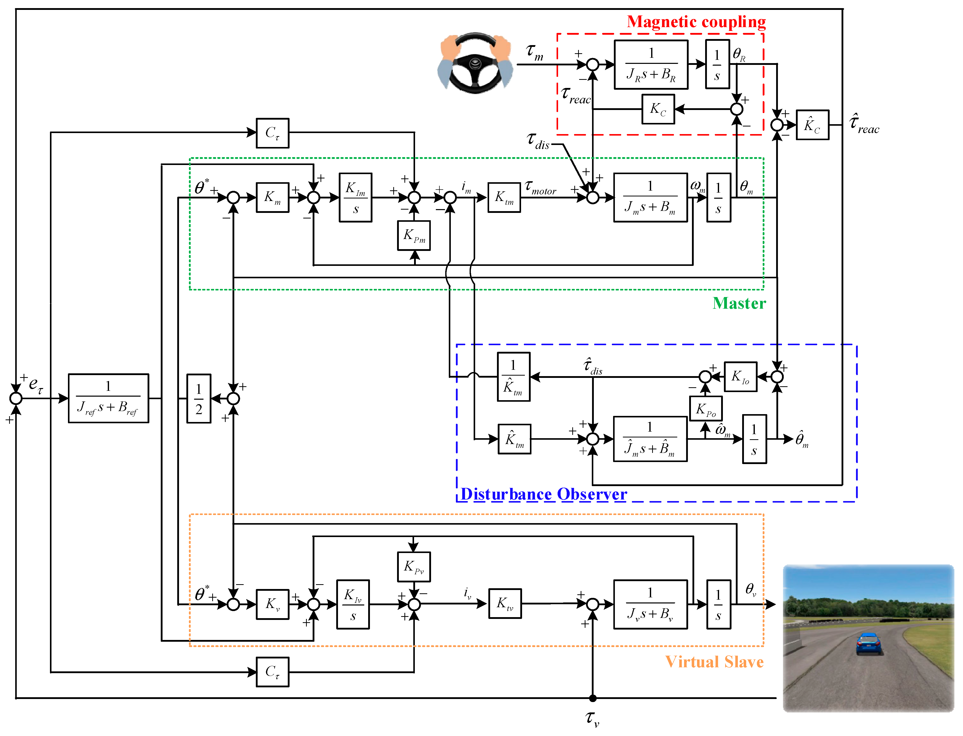
Based on the magnetic coupling of
Figure 7, the overall structure of the bilateral motion control system with magnetic coupling is shown in
Figure 8 where the dynamic model of the magnetic coupling is represented by the Red dashed-line box. By using the estimated reaction torque, Equation (1) can be rewritten as:
This implies that the reaction torque should be the same as environmental load torques applied to the slave in order to produce accurate haptic feedback. The remaining challenge is how to eliminate the effect of .
Since the virtual slave unit will not provide any physical disturbances and uncertainties, the control design that should be considered is only in the physical master unit.
Figure 8 shows the overall configuration where the first layer sensor transmission module design is responsible for acquiring the reaction torque from the torque-measured magnetic coupling. Since the torque-measured magnetic coupling has no backlash,
can be obtained accurately by using high-resolution encoders. As can be seen, an internal loop disturbance feedforward compensation is proposed as shown in the blue dashed-line box in
Figure 8 where the measured reaction torque
is utilized in the disturbance observer. By following the procedure of disturbance decoupling derivation given in [
25], the transfer function from the disturbances
to its observed
is the same as Equation (8). Suppose that the observer bandwidth is designed much larger than that of the speed control loop such that the transient response can be neglected, then
The modified disturbance observer with the measured reaction torque
can effectively estimate the unwanted disturbances
which will then be eliminated as shown in
Figure 8. As the disturbances and/or parameter variation uncertainties can be decoupled properly by the feedforward compensation, the reaction torque measured by the magnetic coupling will only be induced from the virtual side (i.e.,
) in the bilateral control system. Thus, disturbance-free reaction torque is transmitted into the bilateral control system, which will be the same as the virtual load. As a result, the sensation of the haptic feedback felt by the operator can be effectively improved in the proposed bilateral control system.
4. Experimental Results
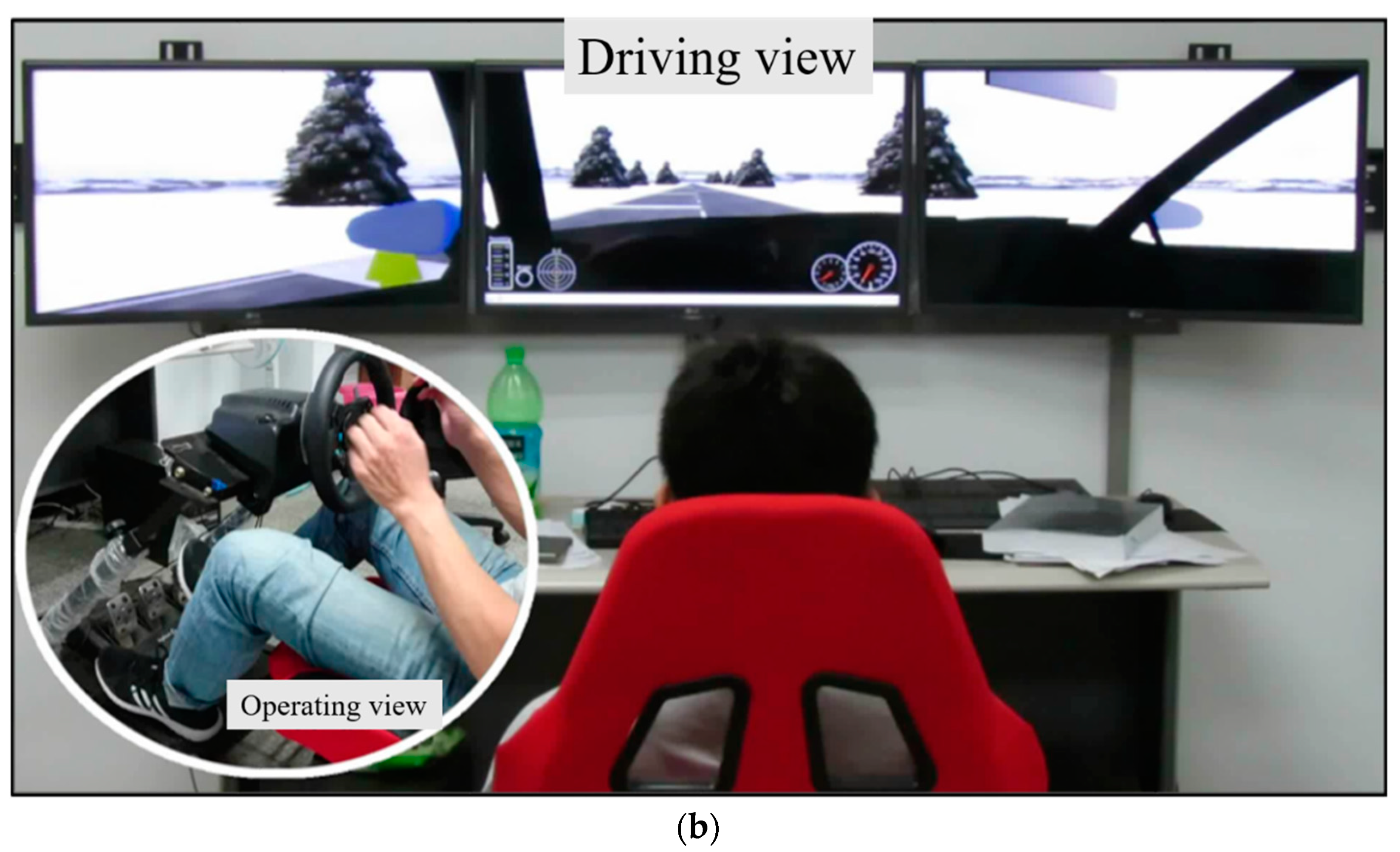
To realize a cyber-physical car-driving simulator system, an experimental setup is shown in
Figure 9a where a servomotor drive unit (400 W rated power output) is coupled with a high-resolution (i.e., 25,000 ppr designed also for use of the disturbance observer) encoder position sensor, a magnetic coupling, and a steering wheel that has an encoder on the master unit in order to develop a virtual steering system. On the slave unit, the CarSIM vehicle dynamic simulation tool is employed to establish the virtual car model and also the driving terrain. With the proposed bilateral control structure, an operator as shown in
Figure 9b, which shows the experimental setup with a user performing the experiment, is able to drive the virtual car system by driving a steering wheel with an additional pedal unit. The virtual external load torque from the terrain’s road conditions is generated by CarSIM according to the simulated vehicle speed and the terrain model, and then will transfer to the real-time Compact RIO Controller. The servomotor is controlled in real time to generate the physical torque sensation such that the operator’s feel for the road conditions will be the same as a real driving experience. It should be noted that this approach is also useful for improving driver skills. The feasibility of the proposed cyber-physical car driving simulator system with haptic feedback is verified by the experimental results. To validate the improvement of the haptic feedback resulting from the proposed bilateral control, a comparison between using the conventional disturbance observer design depicted in
Figure 2 and this proposed magnetic coupling design of
Figure 8 were studied for performance evaluation. The designed bandwidth specifications of each motion loop, controller and model parameters for the control system depicted in
Figure 8 are listed in
Table 1.
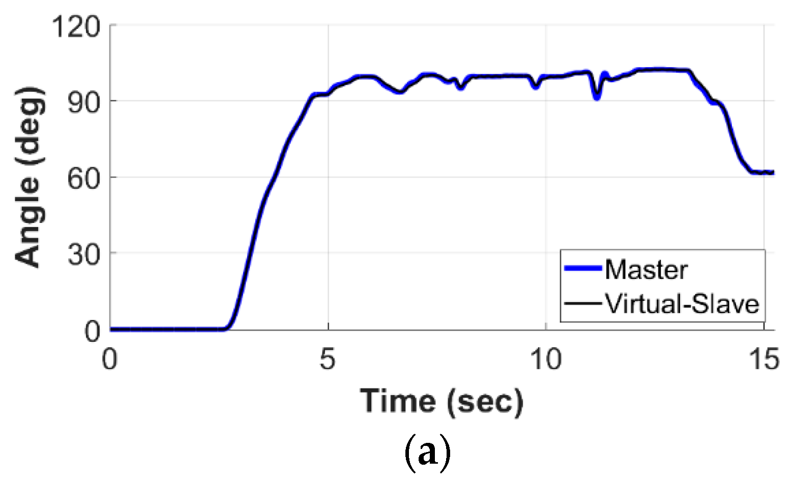
Figure 10 presents the results obtained from the torque observer bilateral control system of
Figure 2 where
Figure 10a shows the position responses of the physical steering system and the virtual plant of the steering wheel. As can be seen here, motion tracking performances between the two sides are in good agreement, which then has verified that the virtual car can be synchronously controlled by driving behavior.
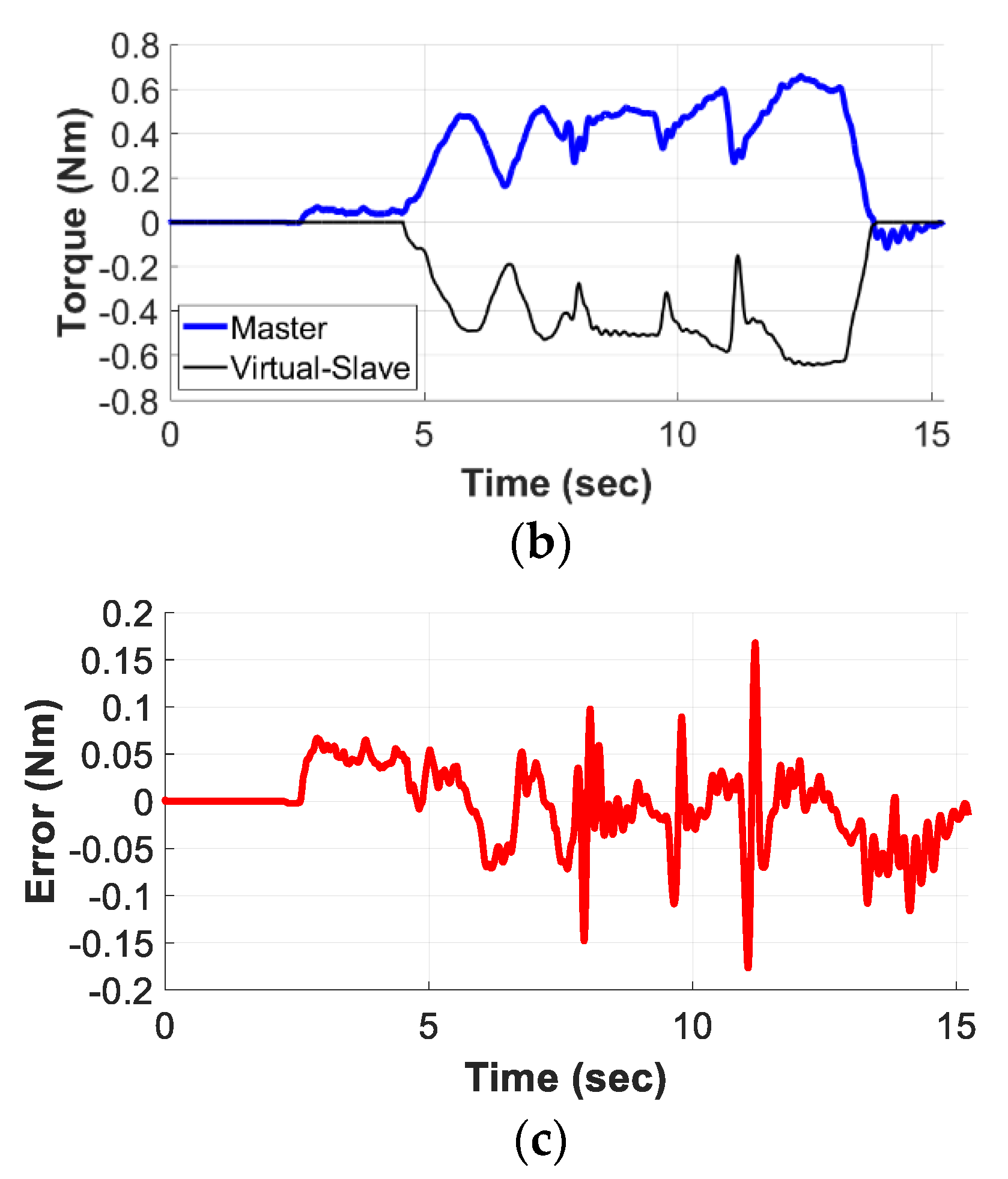
Figure 10b shows the measured haptic feedback torque and the virtual load from CarSIM and
Figure 10c shows the torque error between these two torques (
and
). Obviously, the measured haptic feedback is observed not to be completely the same as the virtual load, when the virtual car is driving and contacting with the virtual terrain road. As depicted in
Figure 10c, the maximum torque error is up to 0.15 Nm. This haptic performance reveals that the operator cannot completely feel the accurate external load torque due to the rough terrain. It should be noted that the virtual load simulated in the CarSIM was properly scaled to correspond with the actual experimental setup.
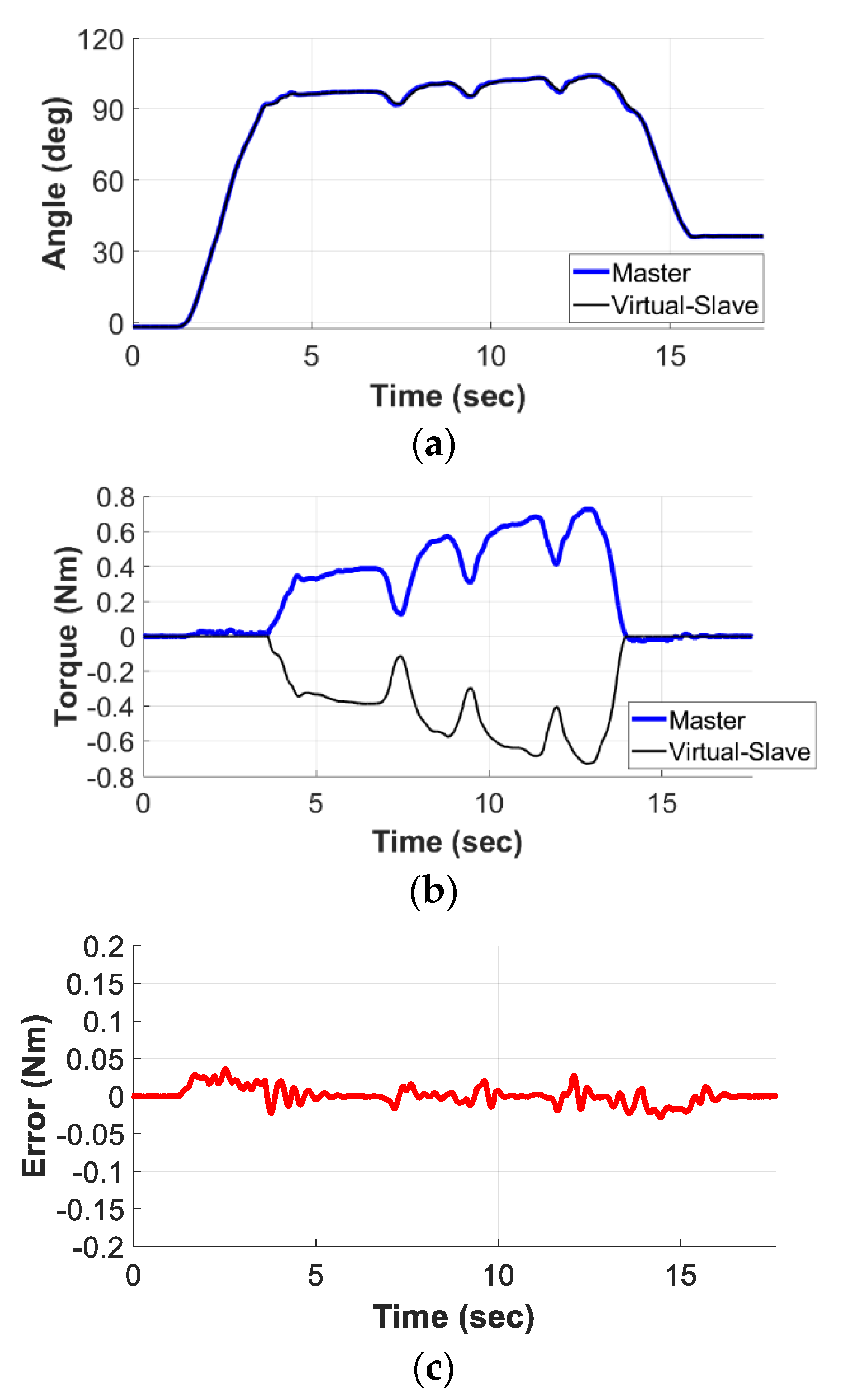
By implementing the proposed bilateral control system of
Figure 8, the experimental results are as shown in
Figure 11. As can be seen, similar to
Figure 10a, the results show a great position tracking performance. Moreover, the measured haptic feedback by the proposed disturbance compensation is also tracked very well and is consistent with the virtual load as measured by the magnetic coupling transmission module. It can be found from the results of
Figure 10c and
Figure 11c that the torque error between
and
becomes much smaller (from 0.15 Nm to less than 0.05 Nm). This concludes that apart from the synchronous motion control between the real operator steering unit and the car moving simulation in the virtual reality system, as expected, the transparency of the haptic feedback can be effectively improved in the proposed bilateral control system.


