Article

Analysis of the Vibration Suppression of Double-Beam System via Nonlinear Switching Piezoelectric Network †

1
Liaoning Key Laboratory of Advanced Measurement and Test Technology for Aviation Propulsion System, Shenyang Aerospace University, Shenyang 110136, China
2
School of Energy and Power Engineering, Beihang University, Beijing 100191, China
3
China Academy of Launch Vehicle Technology, Beijing 100076, China
*
Author to whom correspondence should be addressed.
This paper is an extended version of the paper entitled “Numerical Analysis and Experimental Verification of Synchronized Switching Damping Systems” presented at ASME Conference on Smart Materials, Adaptive Structures and Intelligent Systems, Louisville, KY, USA, 9–11 September 2019.
Machines 2021, 9(6), 115; https://doi.org/10.3390/machines9060115
Submission received: 15 April 2021 / Revised: 4 June 2021 / Accepted: 5 June 2021 / Published: 8 June 2021

Abstract

:
In this paper, a method to suppress the vibration of a double-beam system with nonlinear synchronized switch damping on the inductor via a network (SSDI-net) is proposed. Unlike the classical linear piezoelectric shunt damping, SSDI-net is a nonlinear piezoelectric damping. A double-beam system with SSDI-net was simplified to a lumped parameter electromechanical coupling model and analyzed by using the multi-harmonic balance method, at first with alternating frequency–time techniques (MHBM/AFT). Then, a new lower-power autonomous switching control circuit board was designed, based on SSD technique, and vibration control experiments using a double-beam system with an SSDI network are conducted, to verify the validity of the proposed analysis method and its calculation results. The nonlinear switching piezoelectric network proposed in this article can increase the voltage inversion factor. Furthermore, future applications of this switching piezoelectric network technology in the vibration suppression of bladed-disk structures in aero engines can reduce the number of switches by at least half and obtain almost the same damping effect.

1. Introduction

RL resonant shunting damping is a method to get the optimal damping effect by matching the resonance frequencies of the electrical circuit with the mechanical structure [1,2,3,4]. However, the damping effect of RL shunting is sensitive to the changes in the natural frequencies of the mechanical structure [5,6]. Synchronized switch damping (SSD) using piezoelectric materials is a semi-active piezoelectric damping method, first proposed by Richard et al. [7]. It will produce a damping effect when a synchronized switch circuit is connected across the positive electrode and the negative electrode of the piezoelectric patch bonded on the mechanical structure. When the vibration.
Displacement of the structure reaches the extreme value, the switch will close synchronously and open again quickly, which produces a nonlinear force like the dry friction force [8,9]. Although the SSD shunt is robust, its single-mode damping performance is not as good compared with the linear RL shunt. Then, a synchronized switch damping based on an inductor (SSDI) is applied to the SSD circuit. The inductance increases the charge consumption in the circuit, so a greater damping effect can be obtained. The SSDI method is not sensitive to changes in excitation frequency, and the inductance in SSDI is usually less than that in RL resonant shunting [10,11]. Furthermore, several switch control algorithms [12,13,14] and several self-powered SSD methods [15,16,17] were proposed to improve the energy conversion efficiency of each vibration cycle and obtain better vibration damping over a wider frequency range.
The synchronized switch damping on a negative capacitor (SSDNC) was introduced into SSD technologies by Mokrani et al. [18,19,20]. The negative capacitance circuit in the SSDNC technique produces a damping effect in a wider frequency range by reducing the equivalent value of the inherent piezoelectric capacitance [21]. However, the stability of the SSDNC circuit limits its practical application.
In recent years, linear piezoelectric shunting damping technologies have been introduced into the vibration suppression of complex structures such as aero-engine bladed disks, which opens up a new way of vibration control in integral impellers [22,23,24,25,26,27,28,29,30,31]. Compared with passive shunting damping technologies, semi-active piezoelectric damping technology, represented by SSD, is more suitable for the multi-mode vibration suppression of structures, and it is not sensitive to changes in the external conditions. Therefore, semi-active piezoelectric damping technology will be a trend in the future. At present, the research on SSD techniques is mainly about the vibration suppression of a single-beam structure. It is more practical to introduce the nonlinear SSD method into more complex structures, such as bladed-disk structures in aero engines. In order to apply the SSD method to the vibration control of aero-engine bladed disks, a series of in-depth theoretical studies were made by Liu et al. [8,20]. They established an efficient algorithm for the dynamic characteristics analysis of strongly nonlinear systems, based on MHBM/AFT. However, in their work, each blade connected an SSD shunting circuit, so the control algorithms of switching circuits were all different, which inevitably led to a great increase in the complexity of the whole circuit design.
In view of the prominent advantages of piezoelectric materials in structural vibration suppression, and the problems found in the related research, this paper develops a synchronized switch damping on the inductor via a double-beam system with a network (SSDI-net), and carries out theoretical and experimental studies aimed at the future application of this nonlinear switching network in a bladed-disk structure. For the purpose of simplification and convenience of mechanism study of the SSDI-net system, the two beams in this paper represent two blades of an aero engine. In the future, applications of this switching network technology in the vibration control of bladed-disk structures can reduce the number of switches by at least half. The future objective of this paper is aero-engine bladed-disk vibration suppression, so the work in this paper is significant for engineering applications, especially in aerospace engineering.
The contents of this article are arranged as follows. Firstly, a single-beam model with an SSDI shunt is constructed. Secondly, after the principles of the SSDI network are demonstrated, a double-beam system with an SSDI network is simplified to a lumped parameter electromechanical coupling model and solved in the frequency domain using the MHBM/AFT. Thirdly, a low-power switching circuit is designed. Fourthly, vibration control experiments of a single-beam system with SSDI shunt and a double-beam system with an SSDI network are performed, to verify the validity of the proposed analysis method and the calculation results. The nonlinear switching network proposed in this paper can increase the system damping effect by adding the voltage inversion factor through the circuit design. The experiment results show that the SSDI network constructed in this paper is realizable and effective. In the future, this technique can be used in the vibration suppression of aero-engine bladed disks and can reduce the number of switches by sharing the switches between blades.

2. Single-Beam System with SSDI Shunt

A vibrating cantilevered aluminum beam damped by the action of one piezoelectric patch (piezo-patch for short) is considered, as shown in Figure 1a. The beam is clamped at one end and piezo-patch 1 is bonded on the beam close to the clamped end to connect the SSDI shunt. Piezo-patch 2 is bonded in the same position of the reverse side of the beam to produce the displacement signals. The poling directions of the two piezo-patches are perpendicular to the beam. A harmonic exciting force is applied to the free end of the beam and a nonlinear SSDI circuit is connected to piezo-patch 1.
The equivalent circuit of the SSDI shunt is illustrated in Figure 1b, where L is the inductor in series with the switch, C p is the inherent capacitance of the piezo-patch, and V is the voltage on piezo-patch 1.
The switch is closed only when a displacement extremum occurs. When it is closed, the capacitance C p and the inductance L are working as an electrical vibrator. The switch remains closed until the voltage V on the piezo-patch is reversed, and the closed time t s h u n t is about half a period of the electrical vibrator, as seen in Equation (1). SSDI does not need a high value of inductance, like the traditional RL resonant shunting technique. In practice, the inductance is selected according to the rules by which an inversion time about 20–50 times lower than the vibration period of the host structure is obtained.
t s h u n t = π L C p
The working mechanism of the SSDI circuit is like that used in the dry friction technique, and the damping effect of the SSDI system does not vary with the frequency change. The SSDI principles can also be referenced in [1] by the author.
The nonlinear force generated by the piezo-voltage in the SSDI shunt is in direct proportion to the voltage:
f n l s h u n t ( x , x ˙ , t ) = α p V SSDI ( x , x ˙ , t ) = ( 1 + γ ) α p 2 ( 1 γ ) C p x M sign ( x ˙ ( t ) ) α p 2 C p x ( t )
where α p represents the force factor, that is the force produced by unit voltage, and x M represents the displacement extreme of the host structure in each vibration cycle. α p can be obtained through the method of experiment.

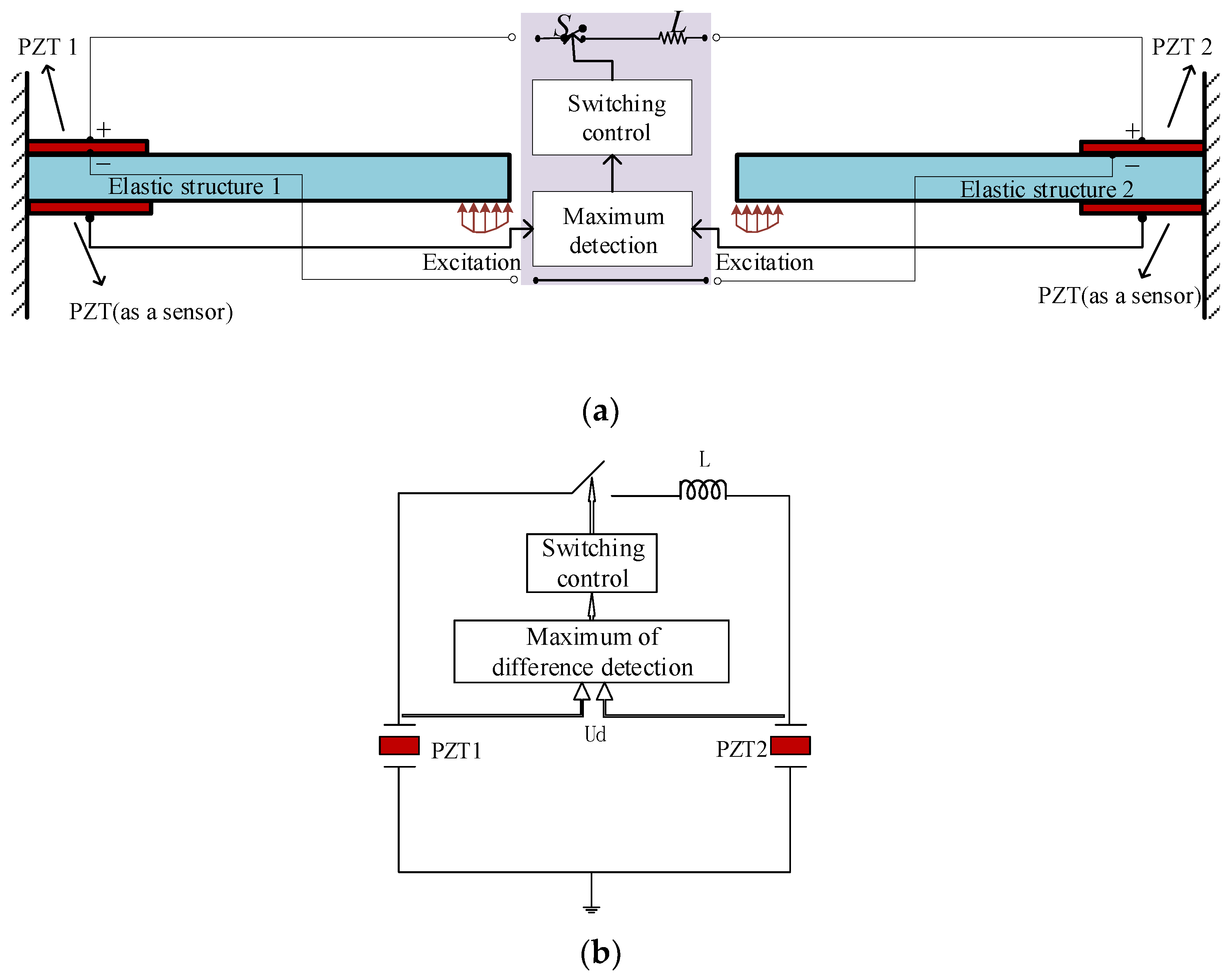
3. Double-Beam System with SSDI Network

The diagram of the aero-engine bladed-disk structure is plotted in Figure 2. The calculations and analysis are very complex if the SSDI network is connected between blades. Therefore, for the sake of simplification, we will first select two blades as the research object and study the vibration reduction mechanism, and then extend the SSDI network to the application of the whole bladed disk. The electromechanical coupling system, including double-beam structure and SSDI network, is taken accordingly as the research object in the following chapters.

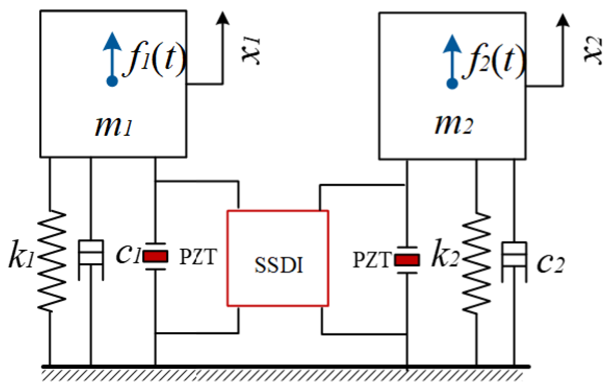
3.1. Modeling of the Double-Beam System with SSDI Network

In order to simulate the vibrations between the blades of the aero-engine bladed disk, two cantilevered beams with exactly the same geometric parameters are studied, as shown in Figure 3a. Piezo-patch 1 and piezo-patch 2 on the top surface of the two beams are connected with the SSDI circuit, while the two piezo-patches on the bottom surface of the two beams are used as sensors to generate displacement signals, to drive the switch in a “closed” or “open” state. The two beams are subjected to periodic exciting forces with the same amplitudes at the free end of the two beams, while the phase difference between the two excitations can be adjusted. The piezo-patches on the top surface of the two beams and the SSDI circuit form an SSDI circuit network, but the control rules of the switching circuit are different from the SSDI in Section 2. The extremum detection circuit senses the displacement difference signals of the two piezo-patches on the bottom surface of the two beams. When the difference reaches the maximum or the minimum, the switch is closed and then it is opened instantaneously. The equivalent circuit is shown in Figure 3b.
It is equivalent that the inherent capacitors of the two piezo-patches are in series in Figure 3b. According to Norton’s theorem, the equivalent capacitance decreases, as shown in Equation (3):
C e q = C p / 2
The closed time T n e t of the SSDI network is written as:
T n e t = π L C e q = π L ( C p 2 )
The electrical quality factor and the voltage inversion factor are deduced accordingly as follows:
Q n e t = 1 R L C e q = 1 R 2 L C p
γ n e t = e π 2 Q n e t
As the equivalent capacitance decreases, the closed time of the switch becomes shorter. Thus, a greater quality factor and a higher voltage inversion factor are obtained in the SSDI network.

3.2. The Lumped Electromechanical Coupling Model

In order to simplify the analysis process, the double-beam piezoelectric system is firstly reduced to a lumped electromechanical coupling model with one DOF per beam, as shown in Figure 4, where m 1 and m 2 represent the two modal masses, k 1 and k 2 represent the two modal stiffnesses relative to the ground, and c 1 and c 2 are the structure damping coefficient, respectively. The mass m 1 is subjected to the external periodic exciting force f 1 ( t ) and the mass m 2 is subjected to the external periodic exciting force f 2 ( t ) . Furthermore, m 1 and m 2 are also subjected to the nonlinear force introduced by the piezo-patch voltage. The forces f 1 ( t ) and f 2 ( t ) have the same excitation frequency but not the same phase.
The differential equations of the lumped system with an SSDI network can be represented as:
{ m 1 x ¨ 1 + c 1 x ˙ 1 + ( k 1 + k e ) x 1 + f nl - net ( x 1 x 2 , x ˙ 1 x ˙ 2 , t ) = f 1 ( t ) m 2 x ¨ 2 + c 2 x ˙ 2 + ( k 2 + k e ) x 2 f nl - net ( x 1 x 2 , x ˙ 1 x ˙ 2 , t ) = f 2 ( t )
where k e represents the stiffness of the piezo-patch, and f nl - net ( x 1 x 2 , x ˙ 1 x ˙ 2 , t ) is the nonlinear force generated by the SSDI network:
f nl - net ( x 1 x 2 , x ˙ 1 x ˙ 2 , t ) = ( 1 + γ n e t ) α p 2 ( 1 γ n e t ) C p ( x 1 x 2 ) M sign ( x ˙ 1 x ˙ 2 ) α p 2 C p ( x 1 x 2 )
To make the analysis more general, Equation (7) is nondimensionalized according to the following equations:
{ τ = ω t λ = ω ω 1 ω 1 = k 1 m 1 δ m = m 2 m 1 γ k = k 2 k 1 γ e = k e k 1 γ m e = α p 2 ( k 1 C p ) , { ξ 1 = c 1 2 m 1 k 1 ξ 2 = c 2 2 m 2 k 2 x ¯ = f 1 k 1 y 1 = x 1 x ¯ y 2 = x 2 x ¯ g 1 ( τ ) = f 1 ( τ ) f 1 g 2 ( τ ) = f 2 ( τ ) f 1
Then the nondimensionalized equations of Equation (10) can be derived as follows:
{ λ 2 y 1 + 2 λ ξ 1 y 1 + ( 1 + γ e ) y 1 + g nl - net ( y 1 y 2 , y 1 y 2 , τ ) = g 1 ( τ ) λ 2 δ m y 2 + 2 λ ξ 2 y 2 + ( γ k + γ e ) y 2 g nl - net ( y 1 y 2 , y 1 y 2 , τ ) = g 2 ( τ )
where g nl - net ( y 1 y 2 , y 1 y 2 , τ ) is the nondimensionalized nonlinear force, which can be expressed as:
g nl - net ( y 1 y 2 , y 1 y 2 , τ ) = ( 1 + γ n e t ) γ m e ( 1 γ n e t ) ( y 1 ( τ ) y 2 ( τ ) ) M sign ( y 1 ( τ ) y 2 ( τ ) ) γ m e ( y 1 ( τ ) y 2 ( τ ) )
Equation (12) can be expressed in the matrix form:
λ 2 M y ( τ ) + 2 λ C y ( τ ) + K y ( τ ) + g nl - net ( y d ( τ ) , y d ( τ ) , τ ) = g ( τ )
where:
M = ( m 1 0 0 m 2 ) , K = ( 1 + γ e 0 0 γ k + γ e ) , C = ( ξ 1 0 0 ξ 2 )
The nonlinear algorithm details to solve Equation (12) regarding the MHBM/AFT can be referenced in [20,32,33,34].

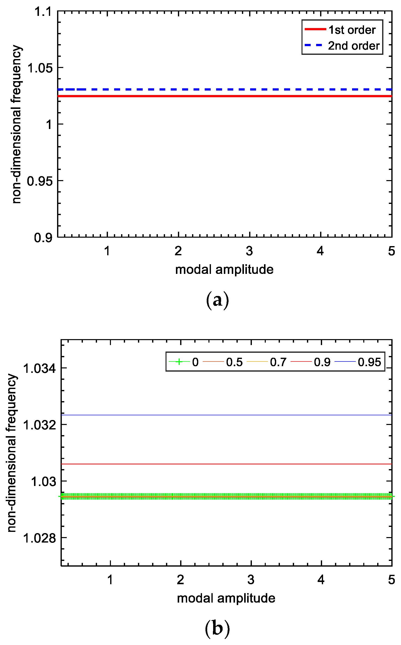
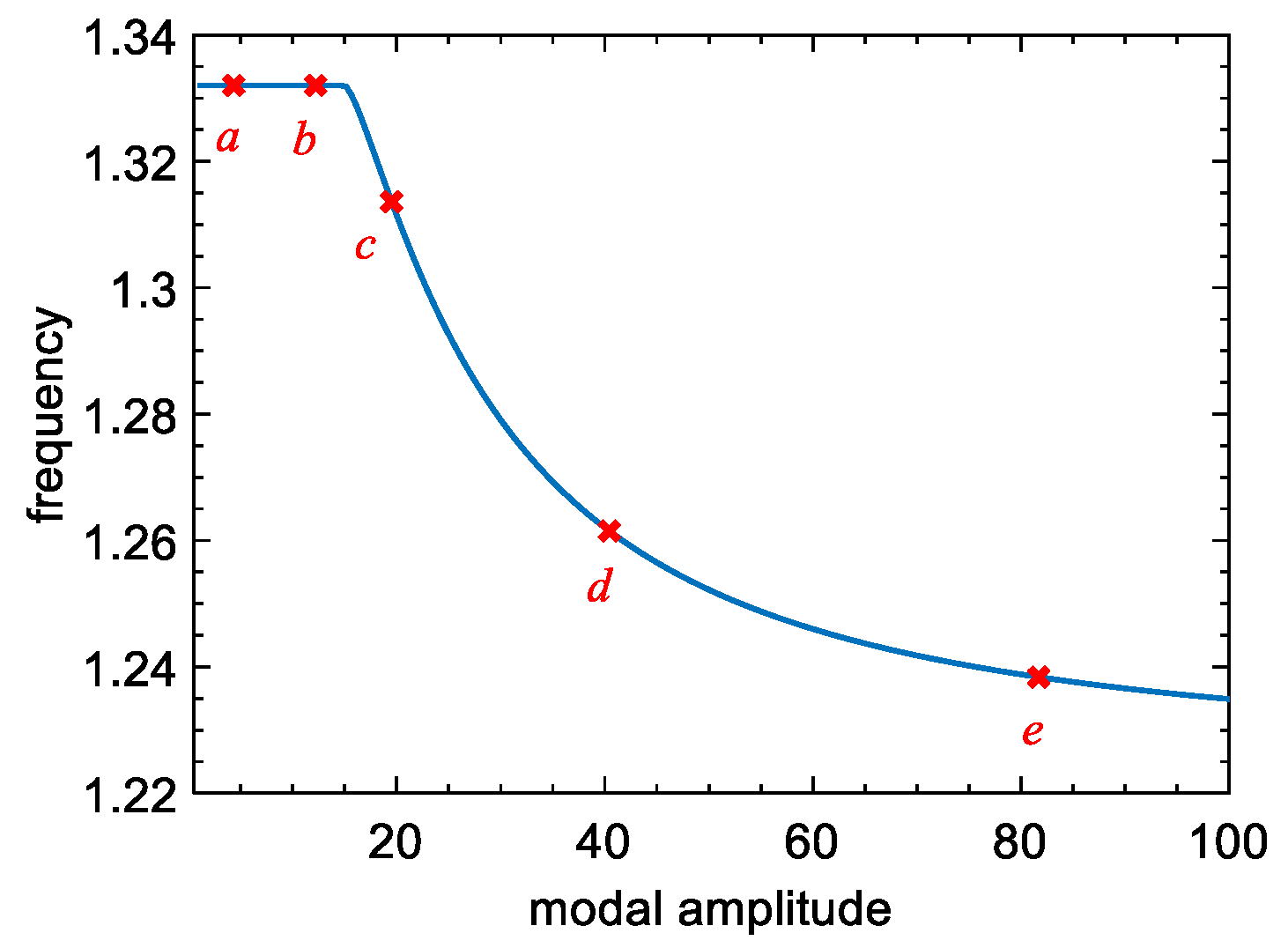
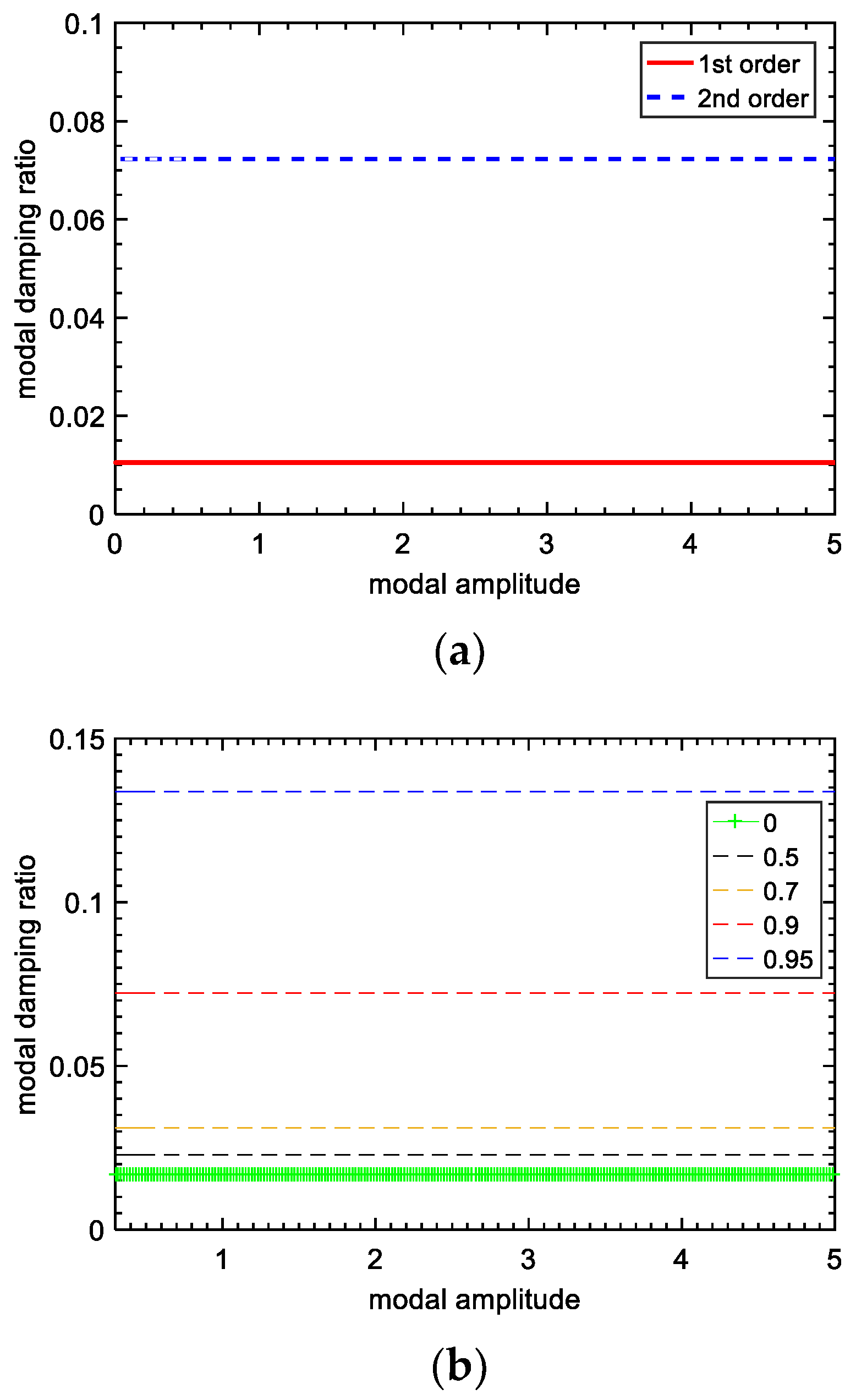
3.3. Nonlinear Complex Modal Analysis

The modal frequencies of the lumped model in Section 3.2 were obtained. Table 1 gives the nondimensionalized parameters of the lumped model.
The curves of the two-order natural frequencies changing with the modal amplitude are plotted in Figure 5a, when γ n e t is equal to 0.9, and the second-order frequency-changing curves (corresponding to the blue line in Figure 5a) in different voltage inversion factors are plotted in Figure 5b. As we can see from Figure 5, the natural frequencies of the two-DOF system with the SSDI network are almost the same, and invariable with the increase in modal amplitude (that is, the amplitude of excitation), which is different from other kinds of nonlinear systems [24]. For a typical nonlinear system, such as a dry-friction system, its frequency changes with the modal amplitude as shown in Figure 6. Usually, there is a typical “skew” phenomenon in the dry-friction system, as shown in Figure 7. However, the piezoelectric system we constructed does not have this phenomenon. It is shown as a straight line; that is to say, the magnitude of external excitation will not affect the frequency of the system, which shows that our piezoelectric system will not bring serious nonlinear characteristics to the system. The straight line represents the connection to the top of the frequency response curve. The variation of each order of frequency of the lumped model when connecting the SSDI network is tiny, compared with the open-circuit case. In addition, the influence of the voltage inversion factor on structure frequencies is minimal. Therefore, the variations of the natural frequencies of the mechanical system are insignificant when an SSDI network is utilized to reduce the vibration.
The curves of the two-order modal damping ratios changing with the modal amplitude are plotted in Figure 8a, and the changing curves of the first-order modal damping ratio with the modal amplitude in different voltage inversion factors are described in Figure 8b. The variation of the modal damping ratio with modal amplitude is mainly to show that a higher voltage conversion factor can improve the damping ratio of the system. From the results, the first-order modal damping ratio and the second-order modal damping ratio of the SSDI system are higher than those of open circuit cases, especially when the voltage inversion factor is higher than 0.9. The larger the voltage inversion factor is, the higher the modal damping ratio that can be obtained.
Figure 5 and Figure 8 mainly explain the influence of a nonlinear piezoelectric circuit on the system from the perspective of mode. From the mechanism analysis, it can be seen that the damping of a nonlinear piezoelectric system can increase with an increase in the voltage inversion factor. The higher voltage inversion factor can be realized through the design of a switch control circuit.
In short, the SSDI network technique can significantly improve the damping level with only a minimal impact on the natural frequencies of the main structure.

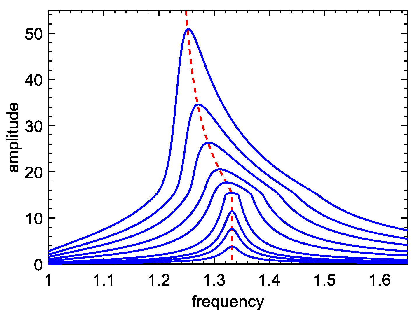
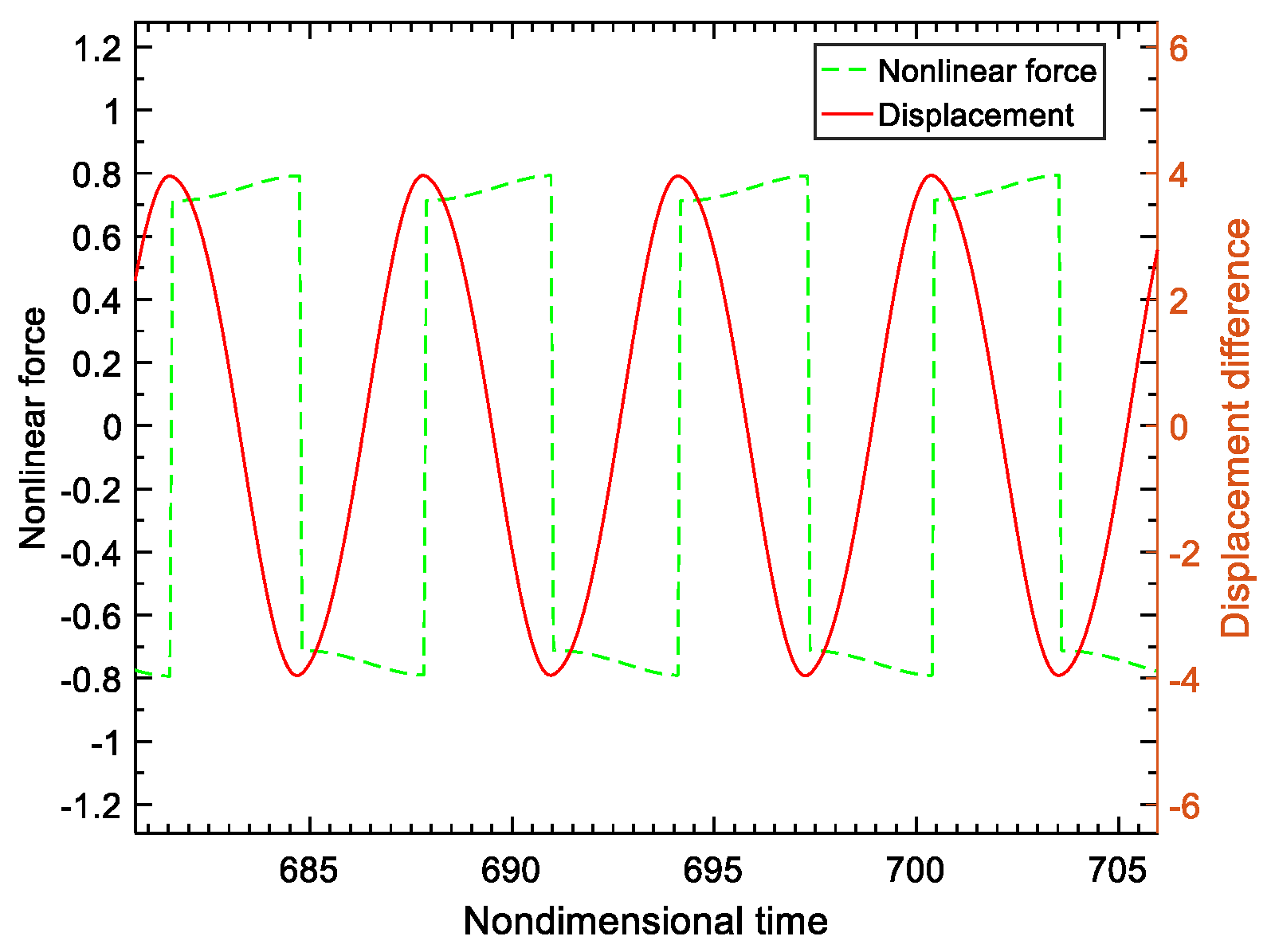
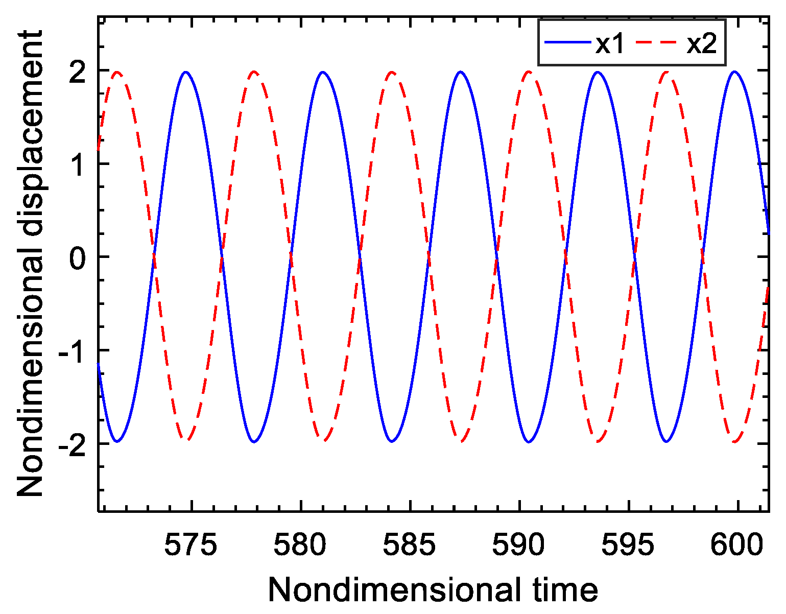
3.4. Forced Response Analysis

The Newmark integration method is time-consuming when calculating the frequency response. If the MHBM/AFT is used to calculate the frequency response, the calculating accuracy is nearly the same as the Newmark integration method, while the calculation speed of MHBM/AFT is 100 times faster than that of the Newmark integration method [1,20].
For the lumped model in Figure 4, the displacement difference curve of m 1 and m 2 , and the nonlinear force curve in the time domain when the exciting frequency is set to 1 and γ n e t is 0.9, are plotted in Figure 9. The loop of nonlinear force vs. displacement difference is described in Figure 10. When the voltage inversion factor γ n e t varies, the nonlinear force generated by the piezo-patch voltage will vary accordingly, as is illustrated in Figure 11. In these figures, the units of displacement and nonlinear force are dimensionless. The higher the voltage inversion factor, the closer the waveform of the nonlinear force is to the rectangle, and the larger the damping effect.
When the exciting forces acting on the two masses have the same amplitudes, but a different phase if γ n e t = 0.9 , the changing curves of the steady-state maximum displacement amplitude of the two masses with the phase difference of the two exciting forces are plotted in Figure 12. It can be seen that the phase difference plays a dominant role when the amplitudes of the exciting forces acting on the two masses are the same. Changing the phase difference of two exciting forces can improve the damping performance of the electromechanical system. When the phase difference of two exciting forces is set to 0°, the amplitudes and the phases of the two masses are identical, with the result that the voltage difference across the switch is zero. The switch is out of action at that moment, and the vibration is not reduced at all. When the phase difference of two exciting forces is set to 180°, the two masses have the same amplitudes but the opposite phase, with the result that the voltage difference across the switch reaches the maximum. This time, the vibration amplitudes of the two masses achieve the same value and the amplitudes approach the minimum, that is, the optimum vibration damping effect can be obtained. The displacement response curves of the two masses, in a time domain when the phase difference of two exciting forces is 180°, are described in Figure 13. Figure 14 is the sweeping frequency comparison curves of the lumped model with and without an SSDI network, when the phase difference of two exciting forces is 180°. It can also be seen that the electromechanical system with an SSDI network has the perfect damping effect when the two exciting forces are antiphase. It is worth noting that the larger the voltage inversion factor, the better the damping effect. When γ n e t = 0.9 , the vibration reduction can be above 90%.

4. Experiment Design

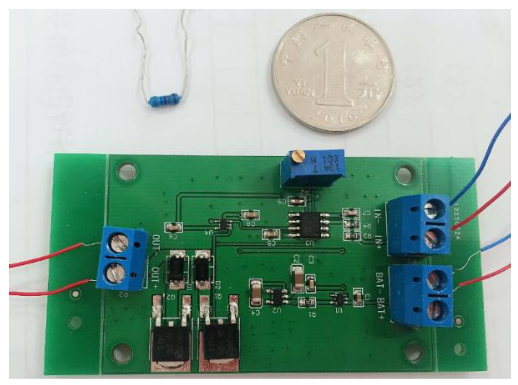
4.1. Implementation of the Low-Power SSDI Circuit

A low-power integrated switching circuit is designed and implemented to fulfill the switch control, and the size of the integrated circuit board is only 60 mm × 40 mm, as shown in Figure 15. Three modules are included in the switching circuit: the battery module, detection module of the displacement extremum and switching control module. A low-pass filter is used to filter the displacement signal and provide a proper phase delay. A comparator is implemented to finish the detection of extremums, by the use of an ultra-low power operational amplifier set in the circuit, and change the displacement signal into a square signal for controlling the switch. The switch function is realized by an NMOS field-effect transistor and a PMOS field-effect transistor (MOSFET) together with two diodes. The types of NMOS and PMOS in the switching control block are NTD20N06 and NTD20P06, respectively. The high-performance ultra-low-power comparator plays an important role in the switching circuit together with the MOSFETs, and it requires just a few μ ws for switching operation. This low-power analog circuit can be powered by a 3V button battery (CR2032), and its battery capacity is 3 V ∗ 210 mAh = 630 mWh. The switching circuit board needs about 0.5mW power in total, which means that with a 3V button battery the whole system can work for 630/0.5 = 1200 h.

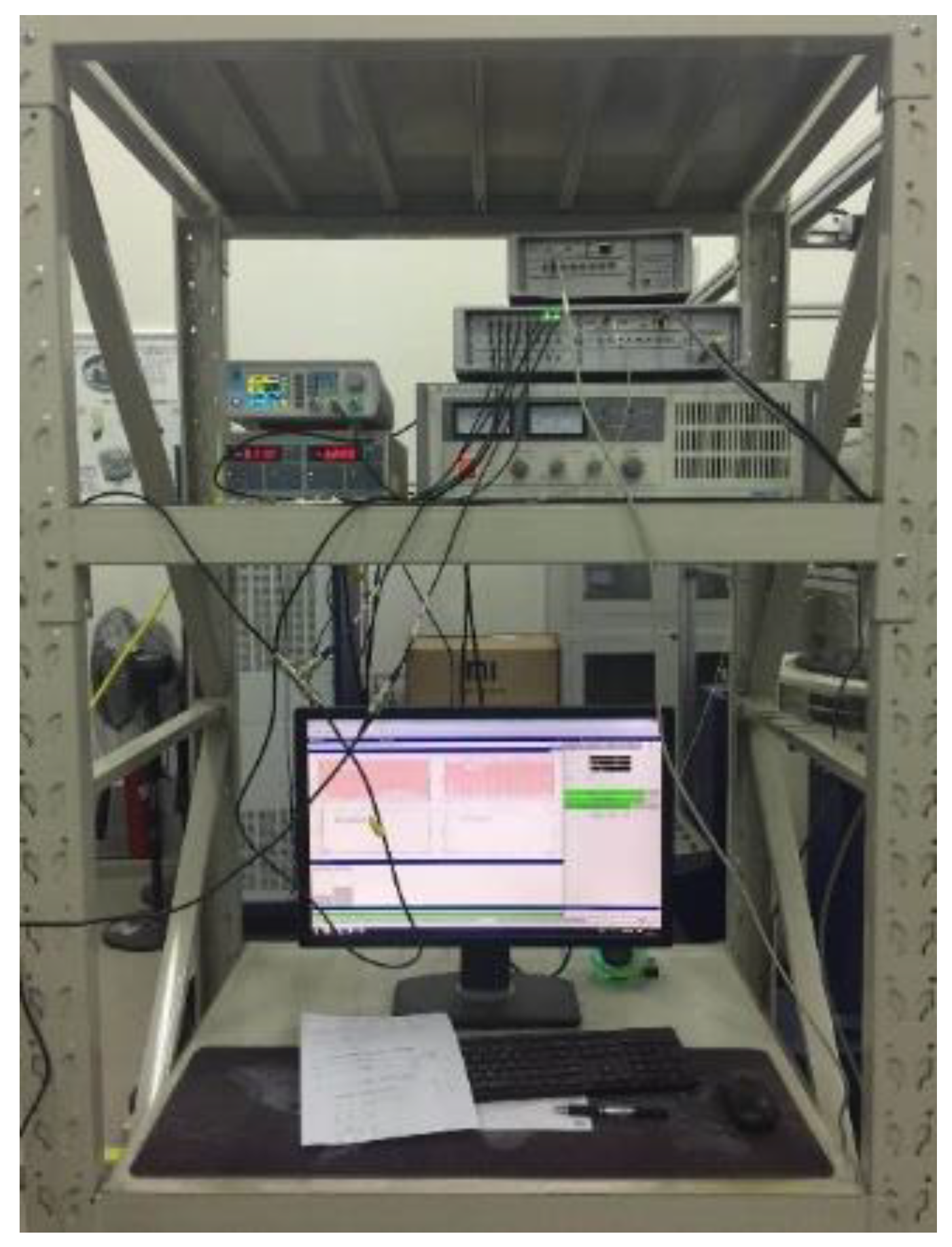
4.2. Experiment Setup

In order to test the validity of the SSD circuit, a single-beam vibration suppression experiment with an SSDI shunt was first conducted and the damping performance of the SSDI shunt system was verified accordingly. Then the double-beam experiment with an SSDI network was performed.

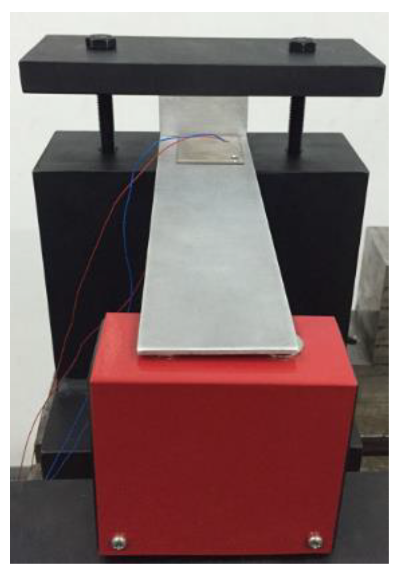
4.2.1. Single-Beam Experiment with SSDI Shunt

The configuration of the beam used in the experiment is shown in Figure 16, and the parameters of the beam are shown in Table 2. PZT 1 was set near the clamped end to connect the SSDI shunt circuit, and PZT 2 was set at the same position on the other surface of the beam to produce displacement signals (expressed by the voltage unit in this experiment) to control the switch. An electromagnetic vibrator was set at the free end of the beam to excite the beam vibration. When a displacement extremum was detected in the voltage signal of PZT2, a trigger signal was generated to turn on the electronic switch, so that the voltage on the PZT1 was inverted. Vibration experiments of the open circuit system were also carried out under the same exciting force to compare the dynamical characteristics of the nonlinear system with an SSDI shunt. The parameters of piezo-patches in this work are demonstrated in Table 3.
In the SSDI shunt, the voltage inversion is realized by using a 100-mH inductor and the integrated switching circuit. Due to the smaller internal resistance (100 Ω) of the new type of inductor and large inductance, the electrical quality factor Q in this article is higher than 10, which produces a large voltage inversion factor ( γ n e t = 0.9 ).

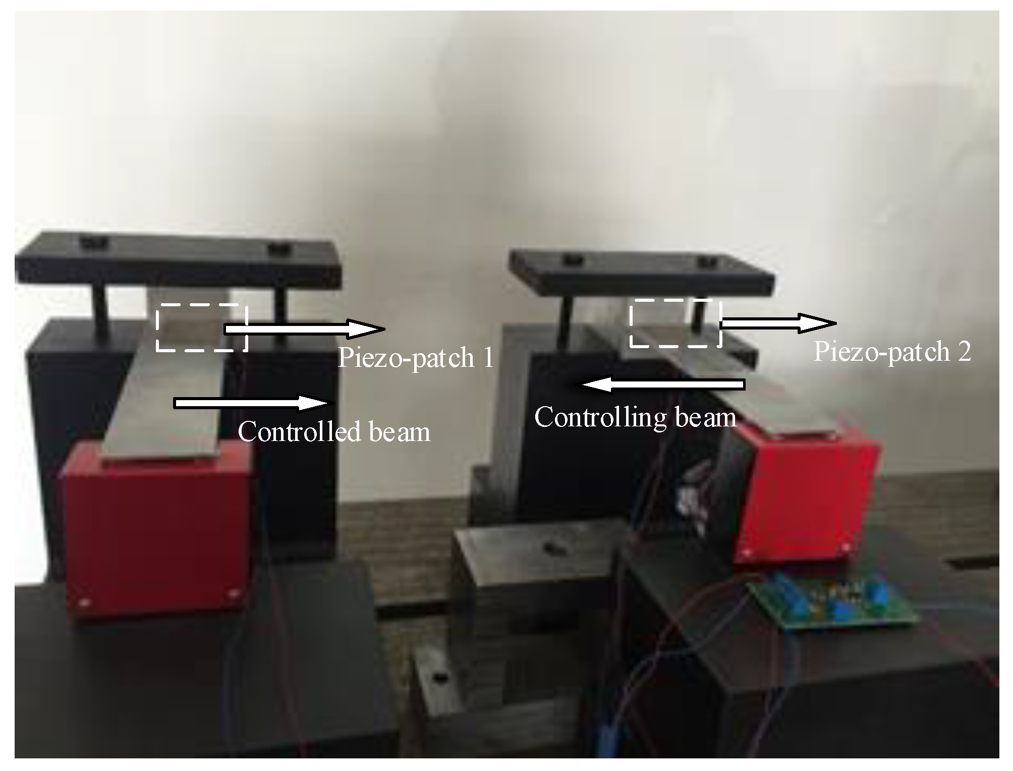
4.2.2. Double-Beam Experiment with SSDI Network

According to the configuration in Figure 3a, two cantilevered beams with exactly the same geometric parameters and four same-type piezo-patches were used to conduct the experiments regarding the SSDI network, as shown in Figure 17. Each beam was arranged according to the single beam in Section 4.2.1. The piezo-patch 1 and the piezo-patch 2 bonded on the top surface of the two beams were connected to the SSDI circuit, while the two piezo-patches on the bottom surface of the two beams were used as sensors to produce displacement signals (measured by voltage unit) to drive the switch. The two beams were excited by electromagnetic vibrators with the same amplitudes at the free ends of the two beams, but the phase difference between the two excitations can be different. The piezo-patches on the top surface of the two beams and the SSDI circuit form an SSDI circuit network. The extremum detection circuit measures the displacement difference (voltage unit) of piezo-patches 1 and 2. When the voltage difference reaches the extremum, the switch is closed and then it is shut off immediately.
There are two kinds of connections in the SSDI circuit network: PP connection and PN connection. In the PP connection, the positive pole of the piezo-patch 1 is connected in series with the positive pole to piezo-patch 2, and the negative poles of the two piezo-patches 1 and 2, are joined together; in the PN connection, the positive pole of piezo-patch 1 is connected in series with the negative pole of piezo-patch 2, and the positive pole of piezo-patch 2 is connected with the negative pole of piezo-patch 1. In the following discussions, the damping effects of the two connection modes will be analyzed and compared with a scenario without any circuit connected.
Besides the electromagnetic vibrator, the equipment used in the experiment also includes the signal generator, the power amplifier, the signal acquisition, and the processing system (as shown in Figure 18).

5. Experimental Results and Discussions

5.1. Single-Beam System with SSDI Shunt

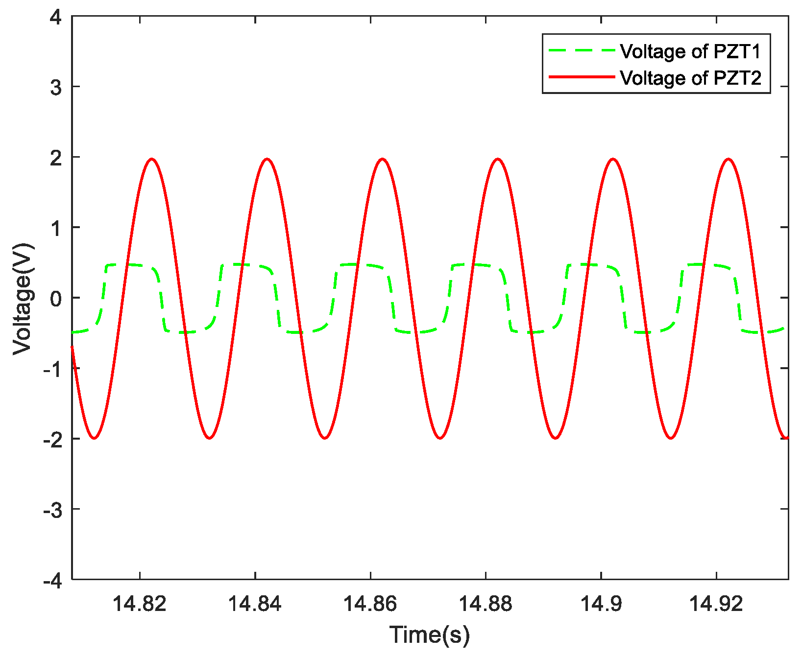
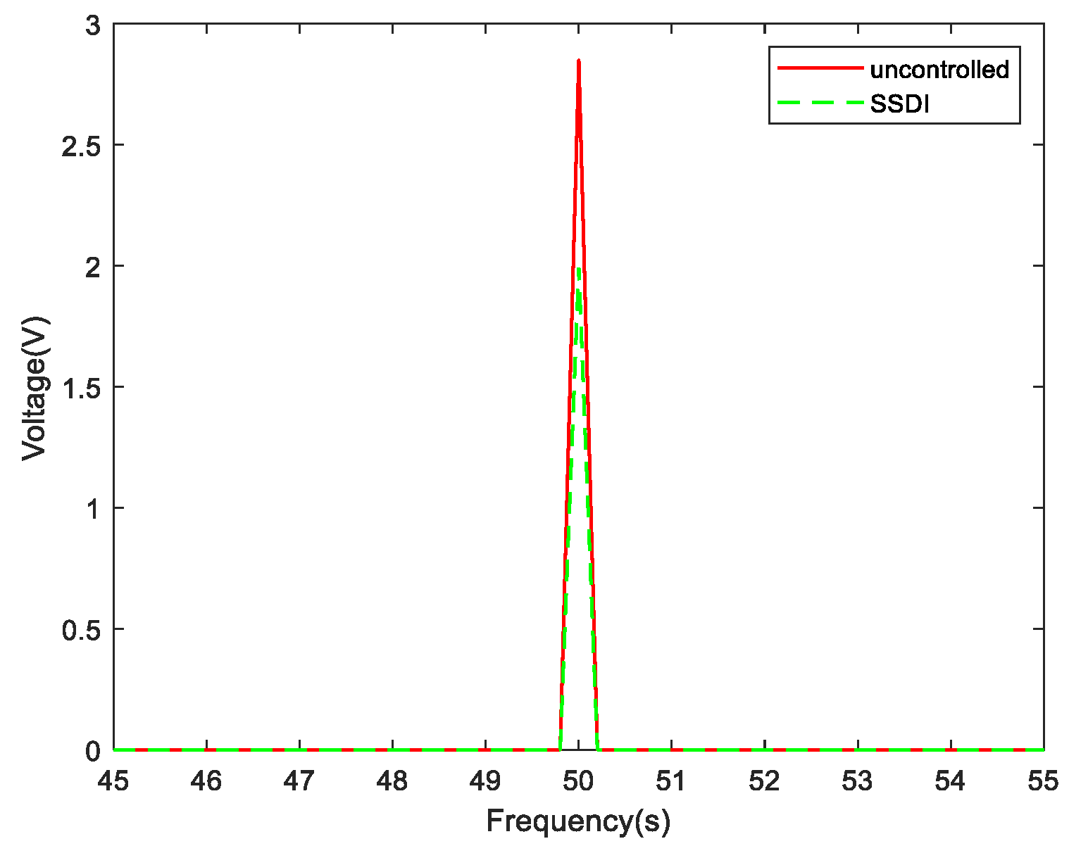
5.1.1. Vibration Control Performance with Single-Frequency Excitation

When the circuit was open, first, a sweeping frequency test was conducted. The waterfall plot is detailed in Figure 19 when the exciting frequency was set from 0 Hz to 400 Hz. As we can see, the first two orders of the resonant frequency of the beam without SSDI circuit were 50 Hz and 280 Hz, respectively.
When the excitation frequency is fixed, the steady-state response of the system in the time domain can be obtained if the number of the vibration cycle is enough. Figure 20 illustrates the evolution of the voltage on piezo-patch 1 with and without an SSDI circuit when the excitation frequency is set to 50 Hz (near the first-order resonance frequency): the solid line corresponds to the open circuit, and the dotted line to the SSDI shunt. The measured steady-state displacement (piezo-patch 2) and voltage response (piezo-patch 1) of the system in the time domain when the excitation frequency is set to 50 Hz is plotted in Figure 21.
The displacement responses (voltage unit) with and without an SSDI circuit, when the excitation frequency is set to the first-order resonance frequency (50 Hz), are illustrated in Figure 22. It shows that the waveforms in the time domain are very clean when the periodic excitation is sinusoidal and single-frequency. The frequency response curves, with and without an SSDI shunt when the exciting frequency is set to 50 Hz, are plotted in Figure 23. As we can see, the displacement amplitude of the system with SSDI shunt is reduced significantly (about 30%) compared with the uncontrolled scenario.

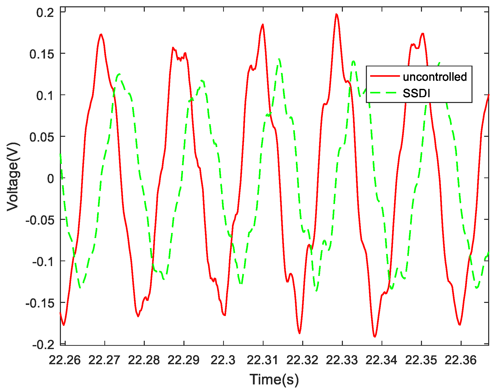
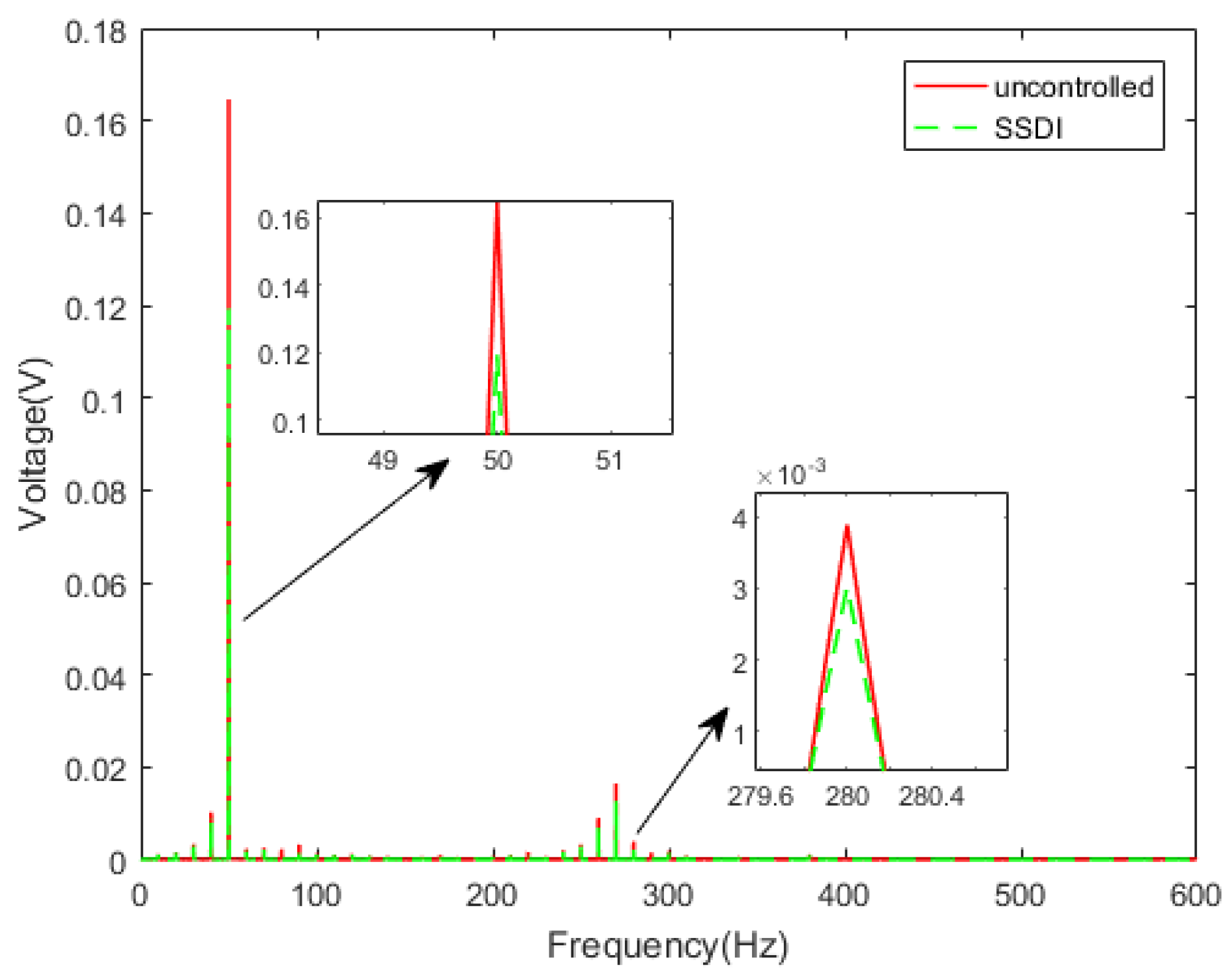
5.1.2. Multi-Mode Vibration Control Performance

The damping performance of the SSDI shunt under multi-mode excitation was studied experimentally, aiming at the first two bending modes (about 50 Hz and 280 Hz) when the exciting signal of the electromagnetic vibrator is white noise. The displacement responses with and without an SSDI in the time domain are plotted in Figure 24, while the displacement responses in the frequency domain are plotted in the following Figure 25. The damping effect is summarized in Table 4, in terms of the voltage amplitude reduction in piezo-patch 2, with an overview of the experimental results.
Because the vibration signal is affected by an external signal, such as a noise signal and circuit interference frequency, there will be some interference frequency in the collected signal. After carrying out an FFT transform on the time domain signal (Figure 24), the vibration amplitude corresponding to the excitation frequency can be observed in the spectrum (Figure 25). The purpose is to remove the influence of interference noise.
It can be seen from Table 4 that the first-order amplitude maximum of the response of the SSDI system can be reduced by about 27.5%, and the second-order maximum of the response can be reduced by about 22.1%, compared with the uncontrolled system. It is proved again that the SSDI shunt has a multi-mode damping effect, and it is not so sensitive to the inductance value as the traditional linear RL shunt. In addition, it is revealed by the experiment that the proposed integrated circuit designed for SSDI has the function of filtering the displacement signal. Even when the displacement amplitude was very small, the switch was still working.
As we said in the introduction, there has been much research on separate beams with piezoelectric circuits in the past, but the ultimate goal of the team was to use SSD damping on the bladed disk. Considering that the piezoelectric network has the function of energy conversion between blades, we could establish a channel between different sectors through the circuit, which achieved the purpose of energy homogenization of the mistuned bladed disk while reducing vibration. The team was trying to simulate the real vibration of the bladed disk in future scenarios, as shown in the following Figure 26.

5.2. Double-Beam System with SSDI Network

According to the previous calculation results, the vibration control effect is best when the amplitudes of two exciting forces acting on the two beams are the same and the phase difference is set to 180° (as shown in Figure 12). Here, we call the left beam the controlled beam and the right beam the controlling beam (Figure 17), that is, we used the right beam to control the left beam. In the experiments of a double-beam system with an SSDI network, the exciting force phase of beam 1 is fixed to 0° and the phase of beam 2 is adjustable from 0° to 360°. Three circuit connection modes were considered: open circuit, PP mode and PN mode. The displacement response curves of the controlled beam in three cases when the exciting frequency is 50 Hz are described in Figure 27. It can be seen that the PN connection mode has the best damping effect, and the PP mode is better than the open-circuit mode. The vibration reduction in the PP mode is about 16%, and the vibration reduction in the PN mode is about 44%, compared with that of the open-circuit mode. When the two beams are excited by the white noise, the displacement response curves of the controlled beam in three cases are presented in Figure 28a and the corresponding frequency response curves are shown in Figure 28b. This also proves that two-order main frequencies and frequency multiplications are all suppressed when the SSDI network is applied, especially in the PN connection mode. The maximum vibration reduction of the PN connection mode is about 40% over a wide frequency band.

6. Conclusions

In this study, a new lower-power autonomous switching control circuit board has been designed, based on the SSD technique. The damping performance of the SSD electromechanical coupling system depends on a high inversion factor and good synchronization of the switch. The nonlinear switching circuit proposed in this article can increase the voltage inversion factor through the low-power comparator, to generate square signals for controlling the switch, and this circuit is not so sensitive to disturbance in the natural frequencies of the host structure as the traditional linear RL shunting. Furthermore, this SSD circuit does not need a huge inductance.
According to the nonlinear complex modal analysis, the changing of the natural frequencies of the mechanical system is minimal when an SSDI circuit is utilized to reduce the structure vibration. The larger the voltage inversion factor, the higher the modal damping ratio.
By comparing the calculation results with the experimental results, it is demonstrated that the MHBM/AFT technique can be used to analyze the dynamic characteristics of the nonlinear electromechanical coupling system, and the calculation speed has been greatly improved.
The vibration control performance obtained by the proposed SSDI network has been compared with the uncontrolled system. The experimental results show that the voltage inversion factor of the SSDI network is improved compared with an SSDI shunt in the same conditions, resulting in a better damping effect. When the amplitudes of the exciting forces acting on the two beams are the same, changing the phase difference of two exciting forces can improve the damping performance of the electromechanical system. Furthermore, the number of switches is reduced by half compared with the independent SSDI shunt technique, which is meaningful for future applications in aero-engine engineering.
For the study of two cantilever beams (representing two blades), only the effect of phase is considered in this article. Only when the two beams have phase differences will the switch start. In the future, the team will propose a concept of sharing switches in the structure of a bladed disk, which can reduce the vibration of the bladed disk in the case of in-phase or out-of-phase.
Furthermore, the self-powered system could be considered to replace the battery of the integrated switching circuit board.

Author Contributions

F.Z. researched calculation methods and wrote the manuscript. J.L. designed the experiment and analyzed Data. J.T. researched approach and validated the results. All authors have read and agreed to the published version of the manuscript.

Funding

This research was funded by Natural Science Foundation of Liaoning Province (Grant no. 2020-BS-174), Research Start-up Funding of Shenyang Aerosapce University (Grant no. 120421004), and Project of Liaoning Provincial Department of Education (Grant no. JYT2020033 and JYT2020019).

Institutional Review Board Statement

“Not applicable” for studies not involving humans or animals.

Informed Consent Statement

“Not applicable” for studies not involving humans.

Data Availability Statement

The data presented in this study are available on request from the corresponding author.

Conflicts of Interest

The authors declare no conflict of interest.

References

  1. Zhang, F.; Li, L.; Fan, Y.; Liu, J. Numerical Analysis and Experimental Verification of Synchronized Switching Damping Systems. In Proceedings of the ASME 2019 Conference on Smart Materials, Adaptive Structures and Intelligent Systems, Louisville, KY, USA, 9–11 September 2019. [Google Scholar] [CrossRef]
  2. Hagood, N.W.; von Flotow, A. Damping of Structural Vibrations with Piezoelectric Materials and Passive Electrical Net-works. J. Sound Vib. 1991, 146, 243–268. [Google Scholar] [CrossRef]
  3. Davis, C.L.; Lesieutre, G.A. A modal strain energy approach to the prediction of resistivity shunted piezoceramic damping. J. Sound Vib. 1995, 184, 129–139. [Google Scholar] [CrossRef]
  4. Thomas, O.; Ducarne, J.; Deü, J.-F. Performance of piezoelectric shunts for vibration reduction. Smart Mater. Struct. 2011, 21. [Google Scholar] [CrossRef] [Green Version]
  5. Ducarne, J.; Thomas, O.; Deü, J.F. Placement and dimension optimization of shunted piezoelectric patches for vibration reduction. J. Sound Vib. 2012, 331, 3286–3303. [Google Scholar] [CrossRef]
  6. Clark, W.W. Vibration control with state-switching piezoelectric materials. J. Intell. Mater. Syst. Struct. 2000, 11, 263A–271A. [Google Scholar] [CrossRef]
  7. Richard, C.; Guyomar, D.; Audigier, D.; Ching, G. Semi-passive damping using continuous switching of a piezoelectric device. In Proceedings of the 1999 Symposium on Smart Structures and Materials, San Diego, CA, USA, 1 March 1999. [Google Scholar]
  8. Jiuzhou, L.; Lin, L.; Yu, F. A comparison between the friction and piezoelectric synchronized switch dampers for blisks. J. Intell. Mater. Syst. Struct. 2018, 29, 2693–2705. [Google Scholar]
  9. Richard, C.; Guyomar, D.; Audigier, D.; Bassaler, H. Enhanced semi-passive damping using continuous switching of a piezoelectric device on an inductor. In Proceedings of the SPIE’s 7th Annual International Symposium on Smart Structures and Materials, Newport Beach, CA, USA, 6 March 2000. [Google Scholar]
  10. Badel, A.; Lagache, M.; Guyomar, D.; Lefeuvre, E.; Richard, C. Finite Element and Simple Lumped Modeling for Flexural Nonlinear Semi-passive Damping. J. Intell. Mater. Syst. Struct. 2007, 18, 727–742. [Google Scholar] [CrossRef]
  11. Guyomar, D.; Lallart, M. Recent Progress in Piezoelectric Conversion and Energy Harvesting Using Nonlinear Electronic Interfaces and Issues in Small Scale Implementation. Micromachines 2011, 2, 274–294. [Google Scholar] [CrossRef] [Green Version]
  12. Cherif, A.; Meddad, M.; Eddiai, A.; Zouhair, A.; Zawadzka, A.; Migalska-Zalas, A. Multimodal vibration damping using energy transfer. Opt. Quantum Electron. 2016, 48, 1–13. [Google Scholar] [CrossRef] [Green Version]
  13. Ji, H.; Qiu, J.; Zhu, K.; Badel, A. Two-mode vibration control of a beam using nonlinear synchronized switching damping based on the maximization of converted energy. J. Sound Vib. 2010, 329, 2751–2767. [Google Scholar] [CrossRef]
  14. Guyomar, D.; Badel, A. Nonlinear semi-passive multimodal vibration damping: An efficient probabilistic approach. J. Sound Vib. 2006, 294, 249–268. [Google Scholar] [CrossRef]
  15. Lallart, M.; Lefeuvre, E.; Richard, C.; Guyomar, D. Self-powered circuit for broadband, multimodal piezoelectric vibration control. Sens. Actuators A Phys. 2008, 143, 377–382. [Google Scholar] [CrossRef]
  16. D’Assunção, D.; De Marqui Junior, C. Applied self-powered semi-passive control for a 2-degree-of-freedom aeroelastic typical sec-tion using shunted piezoelectric materials. J. Intell. Mater. Syst. Struct. 2015, 26, 373–385. [Google Scholar] [CrossRef]
  17. Qureshi, E.M.; Shen, X.; Chang, L. Self-powered synchronized switch damping on negative capacitance for broadband vibra-tion suppression of flexible structures. Int. J. Appl. Electromagn. Mech. 2015, 49, 105–121. [Google Scholar] [CrossRef]
  18. Mokrani, B.; Rodrigues, G.; Burda, I.; Bastaits, R.; Preumont, A. Synchronized switch damping on inductor and negative capacitance. J. Intell. Mater. Syst. Struct. 2012, 23, 2065–2075. [Google Scholar] [CrossRef]
  19. Ji, H.; Qiu, J.; Cheng, J.; Inman, D. Application of a negative capacitance circuit in synchronized switch damping techniques for vi-bration suppression. J. Vib. Acoust. 2011, 133, 041015. [Google Scholar] [CrossRef]
  20. Liu, J.; Li, L.; Huang, X.; Jezequel, L. Dynamic characteristics of the blisk with synchronized switch damping based on negative capacitor. Mech. Syst. Signal Process. 2017, 95, 425–445. [Google Scholar] [CrossRef]
  21. Bao, B.; Lallart, M.; Guyomar, D. Manipulating elastic waves through piezoelectric metamaterial with nonlinear electrical switched Dual-connected topologies. Int. J. Mech. Sci. 2020, 172, 105423. [Google Scholar] [CrossRef]
  22. Zhou, B.; Thouverez, F.; Lenoir, D. An adaptive control strategy based on passive piezoelectric shunt techniques applied to mistuned bladed disks. J. Comput. Appl. Math. 2013, 246, 289–300. [Google Scholar] [CrossRef]
  23. Zhou, B.; Thouverez, F.; Lenior, D. Vibration reduction of mistuned bladed disks by passive piezoelectric shunt damping techniques. AIAA J. 2014, 52, 1–13. [Google Scholar] [CrossRef]
  24. Hohl, A.; Neubauer, M.; Schwarzendahl, S.M.; Panning, L.; Wallaschek, J. Active and semiactive vibration damping of turbine blades with piezoceramics. In Active and Passive Smart Structures and Integrated Systems 2009; International Society for Optics and Photonics: Washington, DC, USA, 2009. [Google Scholar]
  25. Tang, J.; Wang, K.W.; Zhang, J.H. Vibration control of rotationally periodic structures using passive piezoelectric shunt net-works and active compensation. J. Vib. Acoust. 1999, 121, 379–390. [Google Scholar] [CrossRef]
  26. Tang, J.; Wang, K.W. Vibration Delocalization of Nearly Periodic Structures Using Coupled Piezoelectric Networks. J. Vib. Acoust. 2003, 125, 95–108. [Google Scholar] [CrossRef]
  27. Yu, H.B.; Wang, K.W.; Zhang, J.H. Piezoelectric networking with enhanced electromechanical coupling for vibration delo-calization of mistuned periodic structure—Theory and experiment. J. Sound Vib. 2006, 295, 246–265. [Google Scholar] [CrossRef]
  28. Fan, Y.; Li, L. Vibration Dissipation Characteristics of Symmetrical Piezoelectric Networks with Passive Branches. In Turbo Expo: Power for Land, Sea, and Air; American Society of Mechanical Engineers: New York, NY, USA, 2012. [Google Scholar]
  29. Li, L.; Deng, P.; Fan, Y. Dynamic characteristics of a cyclic-periodic structure with a piezoelectric network. Chin. J. Aeronaut. 2015, 28, 1426–1437. [Google Scholar] [CrossRef] [Green Version]
  30. Mokrani, B.; Bastaits, R.; Horodinca, M.; Romanescu, I.; Burda, I.; Viguié, R.; Preumont, A. Parallel piezoelectric shunt damping of rotationally periodic structures. Adv. Mater. Sci. Eng. 2015, 2015, 1–12. [Google Scholar] [CrossRef] [Green Version]
  31. Mokrani, B.; Bastaits, R.; Horodinca, M.; Romanescu, I.; Burda, I.; Viguié, R.; Preumont, A. Piezoelectric Shunt Damping of Rotationally Periodic Structures. Ph.D. Thesis, University of Brussels, Daegu, Korea, 2015. [Google Scholar]
  32. Zhou, B.; Thouverez, F.; Lenoir, D. Essentially nonlinear piezoelectric shunt circuits applied to mistuned bladed disks. J. Sound Vib. 2014, 333, 2520–2542. [Google Scholar] [CrossRef]
  33. Cameron, T.M.; Griffin, J.H. An alternation frequency/time domain method for calculation the steady-state response on non-linear dynamic system. J. Appl. Mech. 1989, 56, 149–154. [Google Scholar] [CrossRef] [Green Version]
  34. Joannin, C.; Chouvion, B.; Thouverez, F.; Ousty, J.-P.; Mbaye, M. A nonlinear component mode synthesis method for the computation of steady-state vibrations in non-conservative systems. Mech. Syst. Signal Process. 2017, 83, 75–92. [Google Scholar] [CrossRef] [Green Version]
Figure 1. Configuration of the single beam with the SSDI shunt: (a) model of the single beam with the SSDI shunt; (b) the equivalent circuit of the SSDI shunt.
Machines 09 00115 g001
Figure 2. Diagram of the aero-engine bladed disk (blisk).
Machines 09 00115 g002
Figure 3. Configuration of the double-beam system with SSDI network: (a) model of the double-beam system with SSDI network; (b) the equivalent circuit of an SSDI network.
Machines 09 00115 g003
Figure 4. Lumped model of the double-beam system.
Machines 09 00115 g004
Figure 5. Frequency vs. modal amplitude: (a) frequencies of the lumped model; (b) frequency change in different γ n e t s.
Machines 09 00115 g005
Figure 6. Frequency vs. the modal amplitude curve of a dry-friction system.
Machines 09 00115 g006
Figure 7. “Skew” phenomenon of the dry-friction system.
Machines 09 00115 g007
Figure 8. Modal damping ratio vs. modal amplitude: (a) modal damping ratios of the lumped model; (b) modal damping ratio changing curves in different γ n e t s.
Machines 09 00115 g008
Figure 9. Displacement difference and nonlinear force.
Machines 09 00115 g009
Figure 10. Nonlinear force vs. displacement difference.
Machines 09 00115 g010
Figure 11. Nonlinear force curves in different γ n e t s.
Machines 09 00115 g011
Figure 12. Nondimensional amplitude vs. phase difference (o) ( γ n e t = 0.9 ) .
Machines 09 00115 g012
Figure 13. Nondimensional displacement curves of the two masses ( γ n e t = 0.9 ) .
Machines 09 00115 g013
Figure 14. Nondimensional frequency vs. nondimensional amplitude.
Machines 09 00115 g014
Figure 15. Circuit board of the switching control.
Machines 09 00115 g015
Figure 16. Single-beam system.
Machines 09 00115 g016
Figure 17. Double-beam system.
Machines 09 00115 g017
Figure 18. Experimental setup.
Machines 09 00115 g018
Figure 19. Sweeping frequency waterfall.
Machines 09 00115 g019
Figure 20. Evolution of the voltages on PZT1 with and without SSDI (50 Hz).
Machines 09 00115 g020
Figure 21. Displacement response (piezo-patch 2) and voltage response (piezo-patch 1) with SSDI shunt (50 Hz).
Machines 09 00115 g021
Figure 22. Displacement comparison curves in the time domain with and without an SSDI (50 Hz).
Machines 09 00115 g022
Figure 23. Displacement comparison curves in the frequency domain with and without an SSDI (50 Hz).
Machines 09 00115 g023
Figure 24. Displacement response curves in the time domain with and without the SSDI (white noise).
Machines 09 00115 g024
Figure 25. Frequency response curves with and without the SSDI (white noise).
Machines 09 00115 g025
Figure 26. Experimental design for the vibration reduction of a bladed disk system excited by a traveling wave.
Machines 09 00115 g026
Figure 27. Displacement comparison curves in three cases (50 Hz): (a) displacement comparison curves; (b) displacement comparison curves (zoom-in).
Machines 09 00115 g027
Figure 28. Damping comparison in three cases (white noise): (a) displacement response curves in the time domain; (b) frequency response curves.
Machines 09 00115 g028aMachines 09 00115 g028b
Table 1. The nondimensionalized parameters of the lumped model.
Variable δ m γ k γ m e γ e ξ 1 ξ 2
Value110.10.050.020.02
Table 2. Aluminum beam characteristics.
VariableLength
(mm)
Width
(mm)
Thickness
(mm)
Elastic Modulus (Gpa)Poisson’s RatioDensity
(kg/m3)
Value200502700.332700
Table 3. Piezo-patch characteristics.
VariableLength
(mm)
Width
(mm)
Thickness
(mm)
Elastic Modulus
(Gpa)
Density
(kg/m3)
Force
Factor
(N/V)
Inherent
Capacitance
(nF)
value43350.56676501.27 × 10−420
Table 4. Damping comparison results of the single beam with and without SSDI shunt.
1st-Order Frequency (Hz)Max Displacement (mV)2nd-Order Frequency (Hz)Max Displacement (mV)
Uncontrolled system50.05164.62803.891
SSDI shunt50.3119.3280.43.03
Publisher’s Note: MDPI stays neutral with regard to jurisdictional claims in published maps and institutional affiliations.

