Article

A Comparative Study on the Condensation Heat Transfer of R-513A as an Alternative to R-134a

1
Halcor-Copper Tube Division, ElvalHalcor Company, 32011 Oinofyta, Viotia, Greece
2
School of Mechanical Engineering & IEDT, Kyungpook National University, Daegu 41566, Korea
*
Author to whom correspondence should be addressed.
Machines 2021, 9(6), 114; https://doi.org/10.3390/machines9060114
Submission received: 7 May 2021 / Revised: 2 June 2021 / Accepted: 3 June 2021 / Published: 6 June 2021
(This article belongs to the Section Electromechanical Energy Conversion Systems)

Abstract

:
This paper presents the two-phase condensation heat transfer and pressure drop characteristics of R-513A as an alternative refrigerant to R-134a in a 9.52-mm OD horizontal microfin copper tube. The test facility had a straight, horizontal test section with an active length of 2.0 m and was cooled by cold water circulated in a surrounding annular space. The annular-side heat transfer coefficients were obtained using the Wilson plot method. The average heat transfer coefficient and pressure drop data are presented at the condensation temperature of 35 °C in the range of 100–440 kg·m−2·s−1 mass flux. The test data of R-513A are compared with those of R-134a, R-1234yf, and R-1234ze(E). The average condensation heat transfer coefficients of the R-513A and R-1234ze(E) refrigerants were similar to R-134a at the lower mass flux (100~150 kg·m−2·s−1), while they were up to 10% higher than R-134a as the mass flux increased. The pressure drop of R-513A was similar to R-1234yf and 10% lower than that of R-134a at the higher mass flux. The R-1234ze(E) pressure drops were 20 % higher compared to those of R-134a at the higher mass flux.

1. Introduction

In recent years, the use of energy systems, including refrigeration and air-conditioning systems, has been gradually increasing due to the advancement of technology and the improvement of living standards. At the same time, energy supply/demand and environmental problems are emerging as important issues. The environmental impacts of refrigeration and air-conditioning systems and their influence on global warming occur during the generation of the working fluids of the system and because of the power required for operation of the systems.
Global warming is highly affected by air-conditioning, refrigeration, and heat pump systems that account for 700 million metric tons of CO2-equivalent direct (7~19%) and indirect emissions (74%) per year [1]. Therefore, it is very important to increase the energy efficiency of such systems and to use eco-friendly alternative refrigerants such as carbon dioxide and hydofluoro-olefin (HFO) refrigerants with smaller global warming potentials (GWP) [2,3,4]. Heat exchangers in air-conditioning and heat pump applications play an important role in the system efficiency and physical size. Finned, round tube, or flat tube heat exchangers are widely used for the evaporators and condensers in residential air-conditioning and heat pump systems.
To investigate the overall performance of the finned-tube heat exchangers, the tube-side heat transfer and pressure drop characteristics as well as airside performance should be investigated simultaneously. Several researchers have conducted investigations into the two-phase thermal and hydraulic performance in smooth and enhanced tubes. Kim and Shin [5,6] experimentally investigated heat transfer characteristics during evaporation and condensation using R-22 and R-410A in 9.52-mm OD smooth and microfin tubes. They found that the average evaporation and condensation heat transfer coefficients of R-410A for microfin tubes were 1.86~3.27 and 1.7~3.1 times larger than those of smooth tubes, respectively.
They also reported that the evaporation heat transfer coefficients of R-410A were 97–129% of those of R-22 when compared to R-22 under the same test conditions. Due to the EU Regulation No. 517/2014, the refrigerant R-134a is already banned in mobile air-conditioning and household refrigerator-freezer systems and will be also prohibited for commercial refrigerator-freezers from 2022 [7]. Hence, studies to find low-GWP alternative refrigerants for R-134a to prevent negative effects on climate change have attracted the attention of many researchers [8].
Aprea et al. [9] conducted experimental research on energy and environmental analysis of drop-in replacements of R-134a in a household refrigerator. They used R-1234yf and R-1234ze (E) and mixtures with R-134a as drop-in alternatives and reported that both mixtures showed a lower environmental impact compared to R-134a. Yıldız and Yıldırım [10] conducted a theoretical and experimental study on R134a, R1234yf, and R513A refrigerants as working fluids for a heat pump at the evaporator (−10, −5, and 0 °C) and condenser (35 °C) temperatures, and found that R-513A and R-1234yf had lower emissions compared to R-134a.
Table 1 and Figure 1 show the general properties and vapor pressures of R-134a compared to the alternative refrigerants R-1234yf, R-1234ze(E), and R-513A. The GWP values of R-1234yf and R-1234ze(E) were significantly lower than R-134a. The thermo-physical properties of refrigerants in Table 1 and Figure 1 were calculated using NIST REFPROP [11]. However, R-1234yf and R-1234ze(E) are mildly flammable and classified as A2L. R-1234ze(E) has a lower saturation pressure than R-134a (75% of R-134a at a saturation temperature of 35 °C); therefore, the design of the system requires modification, and the pressure drop is relatively high.
Zhao et al. [12] investigated film condensation heat transfer characteristics on four different single horizontal low-fin tubes using R-134a and R-404A refrigerants. They found that R-404A condensation heat transfer was more sensitive to low-fin configurations and thermal conductivity compared with that of R-134a. Ji et al. [13] conducted an experimental study on the condensation heat transfer of R-134a, R-1234ze(E), and R-290 outside smooth and enhanced titanium tubes at the condensation temperatures of 35 and 40 °C in the range of heat flux of 8–80 kW/m2. The test results indicated that the overall condensation heat transfer coefficients of R-1234ze(E) and R-290 were lower than that of R-134a for both plain and enhanced tubes.
The R-513A refrigerant is an azeotropic mixture with a mass ratio of R-1234yf and R-134a of 56 to 44, and its GWP is slightly higher at 573; however, it is not flammable and has the advantage that it has very similar thermodynamic properties to R-134a. R-513A is used as a short-term replacement of R-134a for retrofit of an existing system. Diani et al. [14,15,16] performed an experimental study on R-1234yf flow boiling and condensation inside 2.4 and 3.4 mm microfin tubes, respectively.
Longo and Zilio [17] investigated the thermal hydraulic characteristics of R-134a and R-1234yf during condensation in a brazed plate heat exchanger. They found that the heat transfer coefficients and pressure drops of R-1234yf were 10~12% and 10~20% lower, respectively, compared with those of R-134a under the same operating conditions. Yang and Nalbandian [18] conducted experimental studies on the condensation heat transfer characteristics of R-1234yf and R-134a refrigerants in small diameter microfin tubes. The inside tube diameter and the length of the tube were 4.0 mm and 600 mm, respectively. Their results showed that the condensation heat transfer characteristics were strongly dependent on the two-phase flow patterns at various flow conditions.
Li and Hrnjak [19] investigated the evaporation heat transfer, pressure drop, and flow patterns of R-1234yf in a microchannel tube. Kedzierski and Gonclalves [20] conducted experimental works of convective condensation heat transfer of R-134a, R-32, R-125, and R-410A in a microfin tube, and developed a single heat transfer correlation using dimensionless parameters.
Diani et al. [21] presented experimental results of the condensation heat transfer of R-1234ze(E) and R-134a refrigerants inside microfin tubes with an inner diameter of 3.4 mm at saturation temperatures of 30 and 40 °C. They analyzed the effects of refrigerant mass flux and vapor quality on the condensation heat transfer, and they found that the higher the vapor quality, the higher the heat transfer coefficients in the annular flow regime. For vapor quality lower than 0.7, the condensation heat transfer coefficients increased with the refrigerant mass flux. They also found that pressure drops of R-1234ze(E) were 30% higher than those of R-134a.
Diani and Rossetto [22] investigated the evaporation heat transfer characteristics of R-513A at the saturation temperature of 20 °C for mass fluxes of 150–800 kg/m2s and heat fluxes of 12–60 kW/m2 inside a horizontal 3.5-mm ID smooth tube and a 3.4-mm ID microfin tube. They compared the test results with empirical correlation data. Diani et al. [23] investigated the condensation heat transfer of R-513A at the saturation temperatures of 30 and 40 °C in the range of 100~1000 kg·m−2·s−1 mass flux inside 3.5-mm ID smooth and microfin tubes. The results showed that the condensation heat transfer coefficients increased with the refrigerant mass flux and vapor quality.
The purpose of this study is to compare the condensation heat transfer characteristics of R-513A in a microfin tube as a drop-in replacement refrigerant for R-134a. Average condensation heat transfer and pressure drop experiments are conducted inside a 9.52-mm OD microfin tube at a condensation temperature of 35 °C in the range of 100~440 kg·m−2·s−1 mass flux using R-513A, R-134a, R-1234yf, and R-1234ze(E). The correlation equation of the heat transfer coefficient for the annular space of the test section is obtained using the Wilson plot method. The condensation test results of the refrigerant R-513A are compared with those of R-134a, R-1234yf, and R-1234ze(E).

2. Experiments

2.1. Experimental Facility

A schematic of the experimental facility is shown in Figure 2. The facility consists of one refrigerant loop and two water loops [24]. The refrigerant loop is designed to measure the mean heat transfer coefficient of refrigerant condensing inside a microfin tube. It is mainly composed of a gear pump, a pre-heater, a test section, a heat exchanger, a receiver tank, and a sub-cooler. Refrigerant in a liquid state is pumped from the bottom of the receiver tank to the pre-heater where it is heated until it reaches a state of superheated vapor. With the pre-heater, it is possible to control the refrigerant superheat when it enters the test section.
The refrigerant enters the test section in superheated vapor state and leaves as a subcooled liquid. The test section with a length of 2 m consists of a simple tube-in-tube counter flow heat exchanger as shown in Figure 2b. The refrigerant inside the inner tube condenses, and the water that flows in the annular duct between the two tubes is heated. Chiller 1 is designed to control the conditions of the water entering the test section. After the test section, the refrigerant enters the heat exchanger as a subcooled liquid. The role of the heat exchanger is to control the refrigerant pressure; this is accomplished by heating or cooling the refrigerant loop with water as a secondary means.
The heating or cooling rates at the heat exchanger are small in order to accomplish a high precision pressure regulation. Chiller 2 controls the water temperature and flow rate at the inlet of the heat exchanger. The receiver tank contains refrigerant in both liquid and vapor states at the bottom and top, respectively. The refrigerant outlet is located on the bottom of the receiver tank so that only liquid refrigerant is pumped.
The refrigerant pump is a positive displacement gear pump with a maximum flow of 100 kg/h liquid refrigerant. Special attention is given to the refrigerant inlet pressure and temperature conditions to ensure that the refrigerant’s pressure is higher than its vapor pressure at any point in the pump and to avoid any bubble formation within the pump. For that reason, the refrigerant’s pressure and temperature is measured at the suction line to ensure that the refrigerant remains in the liquid state.
The pre-heater is an insulated tank that contains a coil of the main loop refrigerant on the top, electrical resistances on the bottom, and a low-pressure fluid; its role is to heat up the liquid refrigerant to a superheated vapor state. The electrical resistor heaters heat the low-pressure refrigerant that evaporates on the bottom of the tank. Then, low-pressure refrigerant vapor condenses on the surface of the main refrigerant loop coil on the top of the tank.
The test section can be described as a simple tube in a tube heat exchanger. It consists of an inner grooved tube mounted inside an outer shell tube with a diameter of 16 mm, so that the refrigerant flows counter-current through the inner tube with the cooling water around it. Figure 3 shows the tested microfin tube, and it has 60 fins with a fin height (h) of 0.25 mm, an apex angle (Υ) of 30°, helix angle (φ) of 15~30°, ID and OD of 8.92 mm and 9.52 mm, respectively, and bottom wall thickness (tb) of 0.35 mm. The refrigerant condenses in the test section under fully controlled conditions. The pressure and temperature are measured at the inlet and outlet of the test section using temperature sensors (PT100, RTD sensors) and pressure transducers.
The refrigerant pressure drops in the test section are measured with a differential pressure sensor. Both the inlet and outlet state of the refrigerant are single phase; thus, the inlet-outlet specific enthalpies can be determined using thermodynamic data from REFPROP [11]. The measured saturation temperatures were in good agreement with the temperature calculated based on the measured saturation pressure within ±0.3 °C. The condensation heat capacity was calculated as the product of the mass flow and the differential enthalpy. The heat balance between the water and refrigerant side was within the range of ±4.0%. The refrigerant and water flow rates were measured using Coriolis mass flow meters with a nominal flow range of 0~1200 kg/h and an accuracy of ± 0.1%.
The test data were collected using a data recorder and analyzed in real time with a PC running data reduction software. All the information about the test conditions and test data during the experiment were displayed on the monitor, and the test conditions can be changed based on this information.

2.2. Experimental Methods and Conditions

The test conditions are described in Table 2. The condensation experiments were conducted at the saturation temperature of 35 °C for the mass flux of 100~440 kg·m−2·s−1 with R-513A, R-134a, R-1234yf, and R-1234ze(E). The inlet superheating and outlet subcooling of condenser were 5 and 2 °C, respectively. The refrigerant flow was regulated by controlling the input power of the variable speed magnetic gear pump. It was not possible to measure the local heat transfer coefficients with variation of quality due to the limitations of the test facility.
Hence, the average condensation heat transfer coefficients and pressure drop data for the refrigerants considered in the study were measured and compared. The test conditions and data to be collected were monitored throughout the experiment, and data sets were recorded and averaged over 10 min after the test conditions reached steady state. Before the condensation experiment, a series of water-to-water experiments were first performed to find the correlation of the heat transfer coefficient of the annular space. The water-to-water test data were collected with increases of the water flow rate of the annular space from 200–800 kg/h in increments of 100 kg/h.

2.3. Data Reduction

The condensation heat transfer coefficients can be calculated using the following equations:
1 U o A o   =   1 h i A i   +   R w   +   1 h o A o
where UoAo is the overall heat transfer coefficient. The variables hi and ho are the refrigerant side and annular waterside heat transfer coefficients. Rw is the thermal conduction resistance of the tube wall, and it can be neglected because the tube material is copper, and the thickness of the tube wall is very thin. The heat transfer rate of the test section, Q, is described using the log mean temperature difference (LMTD):
Q   =   U o A o   L M T D
where Q is the arithmetic mean of tube-side (Qi) and annular-side (Qo) heat transfer rates that are obtained from the following equations:
Q   =   ( Q i   +   Q o ) / 2  
Q i   =   m i   ( e i 1     e i 2 )
Q o   =   m o c p o   ( T o 2     T o 1 )
where mi and mo are the refrigerant- and water-side mass flow rates, respectively. ei1 and ei2, To1 and To2 are the refrigerant enthalpies and water temperatures at the test section inlet/outlet, respectively. The LMTD can be obtained as:
L M T D   =   ( T i 2     T o 1 )     ( T i 1     T o 2 ) ln [ ( T i 2 T o 1 ) ( T i 1 T o 2 ) ] .
If the heat resistance (1/hoAo) of the annular space is known from Equation (1), the heat transfer coefficient (hi) in the tube can be obtained from the heat resistance (1/hiAi) in the tube. The refrigerant properties were calculated using NIST REFPROP [11]. Accounting for all instrument errors, the uncertainties of the average heat transfer coefficient and pressure drop data were ±3.7~11.3% and ±1.5~8.5%, respectively [25]. The maximum uncertainty for the heat transfer coefficient and pressure drop appeared at the minimum mass flux.

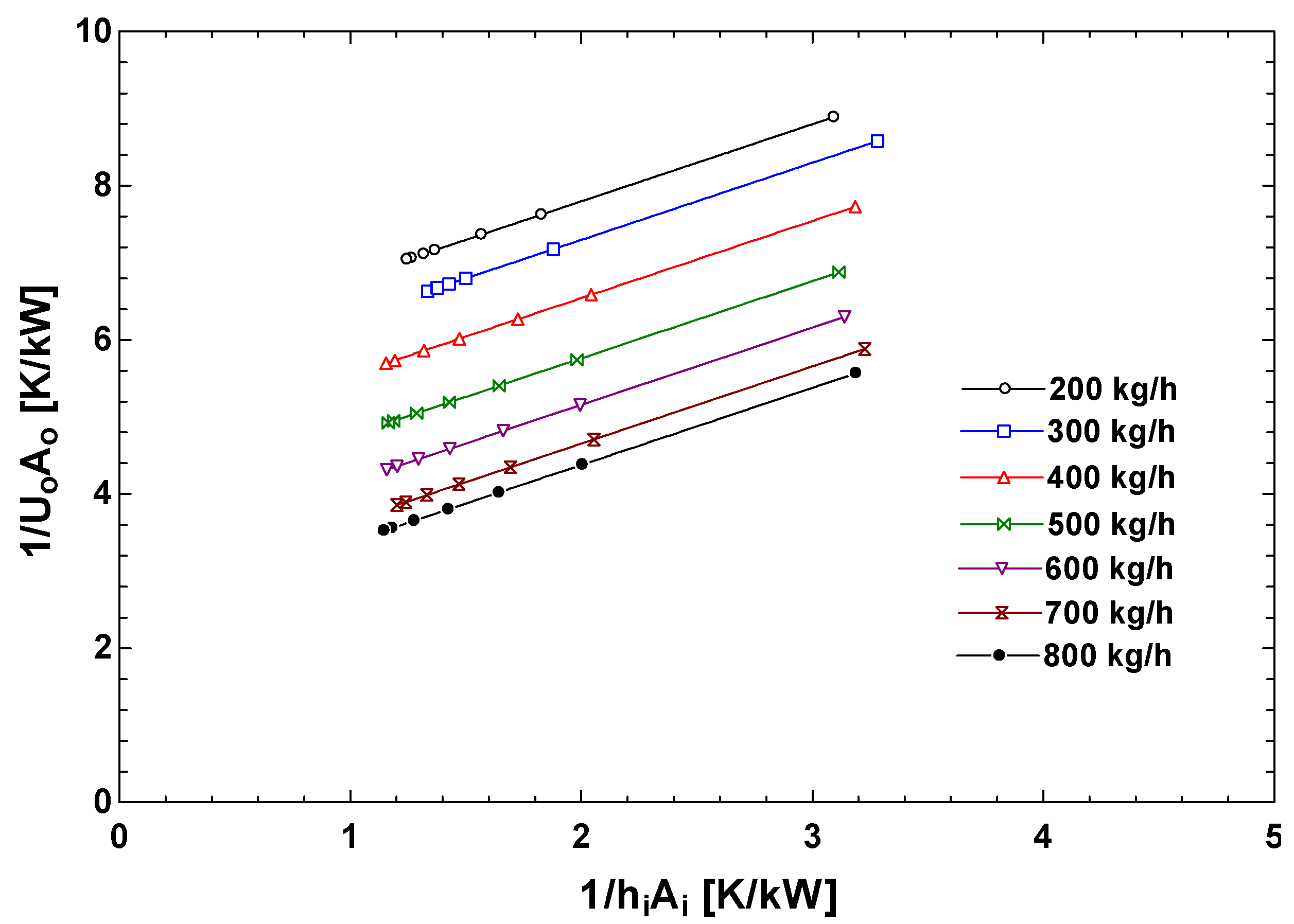
3. Results and Discussion

Figure 4 and Figure 5 show, respectively, the Wilson plot and the correlation equation for obtaining the heat transfer coefficient of the annular space with variation of the water flow rate of 200~800 kg/h. As shown in Figure 4, the total thermal resistance value (1/UoAo) of the test section was well expressed as a function of the tube-side thermal resistance (1/hiAi). The total thermal resistance value decreased with the increase of the flow rate of the annular space at the same flow rate in the tube-side because the heat transfer coefficient of the annular flow path increased with the increase of the flow rate. The refrigerant-side heat transfer coefficients were calculated from Equation (1) using the correlation of 1/hoAo from Figure 5.
Figure 6 and Figure 7 present the average heat transfer coefficients and pressure drops, respectively, at the condensing temperature of 35 °C in the range of 100~440 kg·m−2·s−1 mass flux. The heat transfer coefficients of the test refrigerants, including R-513A, increased with the refrigerant mass flux as expected, and all four refrigerants had similar heat transfer coefficients at low mass flux. However, as the mass flux increased, the heat transfer coefficient of R-513A had a similar value to that of R-1234ze(E), while it was about 10% higher than that of R-134a. The heat transfer coefficient of R-1234yf represents the lowest value among the test refrigerants, and the difference in heat transfer coefficient with other refrigerants became larger as the mass flux increased.
The condensation heat transfer coefficient of R-1234yf is up to 12% lower than that of R-134a in the mass flux range probed in this study. Table 3 presents the major thermodynamic and transport properties of R-134a alternative refrigerants. These properties are attributed to the higher R-513A and R-1234ze(E) heat transfer coefficients and lower R-1234yf heat transfer coefficients compared to R-134a. As shown in Figure 7, the pressure drops of all test refrigerants increased with mass flux as expected.
The pressure drops of R-513A and R-1234yf were smaller than that of R-134a when the mass fluxes were larger than 150 kg·m−2·s−1, while the pressure drops of R-1234ze(E) were relatively higher compared with that of R-134a. The pressure drops of R-513A and R-1234ze(E) were 10% lower and 20% higher than R-134a at the higher mass flux in this study. This is partly due to the higher vapor viscosity of R-1234ze(E) compared to R-134a as shown in Table 4. Overall, R-513A can be used as a short- and mid-term retrofit alternative refrigerant for R-134a due to its relatively good thermo-hydraulic performance and small GWP compared to R-134a.

4. Conclusions

The present study was conducted to investigate two-phase condensation heat transfer and pressure drop characteristics in a horizontal 9.52-mm OD microfin tube with the refrigerant R-513A as an alternative to R-134a. The experimental results of R-513A were compared with those of R-134a, R-1234yf, and R-1234ze. The findings of the present study are as follows:
  • The correlation of annular side heat transfer coefficients was obtained as a function of the water mass flow rate and was used to derive the condensation heat transfer coefficients in a microfin tube.
  • The average condensation heat transfer coefficients of R-513A and R-1234ze(E) were similar to that of R-134a in the lower range of tested mass fluxes (100~150 kg·m−2·s−1).
  • As the mass flux increased, the heat transfer coefficients of R-513A and R-1234ze(E) became up to 10% higher than those of R-134a.
  • The average condensation heat transfer coefficients of R-1234yf were up to 12% lower than those of R-134a for the full range of tested mass fluxes.
  • The pressure drop of R-513A was similar to R-1234yf and 10% lower compared to that of R-134a at the higher mass flux.
  • The R-1234ze(E) pressure drops were 20% higher compared to those of R-134a at the higher mass flux.
  • R-513A can be used as a drop-in replacement for R-134a since it has relatively superior condensation heat transfer characteristics and a smaller GWP compared to R-134a.

Author Contributions

Conceptualization, methodology, formal analysis, and original draft preparation by A.K. and G.H., and M.-H.K. supervised the research and edited the manuscript. All authors have read and agreed to the published version of the manuscript.

Funding

This research received no external funding.

Institutional Review Board Statement

Not applicable.

Informed Consent Statement

Not applicable.

Data Availability Statement

Data are contained within the article.

Conflicts of Interest

The authors declare no conflict of interest.

Nomenclature

Abbreviations
DPdifferential pressure sensor
GWPglobal warming potential
HFOhydofluoro-olefin
IDinner diameter
FMflow meter
LMTDlog mean temperature difference
NBPnormal boiling point
ODouter diameter
ODPozone depletion potential
PCpersonal computer
SGsight glass
Aarea [m2]
cpspecific heat [J/kg-K]
eenthalpy [J/kg]
hheat transfer coefficient [W/m2-K] or fin height [mm]
Mmass flow meter
mmass flow rate [kg/h]
Ppressure[kPa]
ΔPpressure drop[mbar]
qvvolumetric capacity [kJ/m3]
Q heat transfer rate [W]
Rwthermal conduct resistance [K/W]
Sspecific entropy [J/kg-K]
Ttemperature [°C]
tbbottom wall thickness [mm]
U overall heat transfer coefficient [W/m2-K]
γapex angle [°]
ψhelix angle [°]
Subscripts
1inlet
2outlet
c critical
itube-side
o annular-side

References

  1. Blanco, G.; Gerlagh, R.; Suh, S. (Eds.) Drivers, Trends and Mitigation. In Climate Change 2014; Cambridge University Press: Cambridge, UK, 2014; pp. 351–412. [Google Scholar]
  2. Kim, M.-H.; Pettersen, J.; Bullard, C.W. Fundamental Process and System Design Issues in CO2 Vapor Compression Systems. Prog. Energy Combust. Sci. 2004, 30, 119–174. [Google Scholar] [CrossRef]
  3. Kim, M.-H.; Lee, S.Y.; Mehendale, S.S.; Webb, R.L. Microchannel Heat Exchanger Design for Evaporator and Condenser Applications. Adv. Heat Transf. 2003, 37, 297–429. [Google Scholar]
  4. Lin, L.; Kedzierski, M. Review of low-GWP refrigerant pool boiling heat transfer on enhanced surfaces. Int. J. Heat Mass Tran. 2019, 131, 1279–1303. [Google Scholar] [CrossRef]
  5. Kim, M.-H.; Shin, J.S. Evaporating heat transfer of R22 and R410A in horizontal smooth and microfin tubes. Int. J. Refrig. 2005, 28, 940–948. [Google Scholar] [CrossRef]
  6. Kim, M.-H.; Shin, J.S. Condensation heat transfer of R22 and R410A in horizontal smooth and microfin tubes. Int. J. Refrig. 2005, 28, 949–957. [Google Scholar] [CrossRef]
  7. Mota-Babiloni, A.; Makhnatch, P.; Khodabandeh, R.; Navarro-Esbrí, J. Experimental assessment of R134a and its lower GWP alternative R513A. Int. J. Refrig. 2017, 74, 682–688. [Google Scholar] [CrossRef]
  8. Wang, C.-C. An overview for the heat transfer performance of HFO-1234yf. Renew. Sustain. Energy Rev. 2013, 19, 444–453. [Google Scholar] [CrossRef]
  9. Aprea, C.; Greco, A.; Maiorino, A. HFOs and their binary mixtures with HFC134a working as drop-in refrigerant in a household refrigerator: Energy analysis and environmental impact assessment. Appl. Therm. Eng. 2018, 141, 226–233. [Google Scholar] [CrossRef]
  10. Yıldız, A.; Yıldırım, R. Investigation of using R134a, R1234yf and R513A as refrigerant in a heat pump. Int. J. Environ. Sci. Technol. 2021, 18, 1201–1210. [Google Scholar] [CrossRef]
  11. Lemmon, E.W.; Bell, I.H.; Huber, M.L.; McLinden, M.O. NIST Standard Reference Database 23: Reference Fluid Thermodynamic and Transport Properties-REFPROP, Version 10.0, National Institute of Standards and Technology; Standard Reference Data Program: Gaithersburg, MD, USA, 2018. [Google Scholar]
  12. Zhao, C.-Y.; Ji, W.-T.; Jin, P.-H.; Zhong, Y.-J.; Tao, W.-Q. The influence of surface structure and thermal conductivity of the tube on the condensation heat transfer of R134a and R404A over single horizontal enhanced tubes. Appl. Therm. Eng. 2017, 125, 1114–1122. [Google Scholar] [CrossRef]
  13. Ji, W.-T.; Chong, G.-H.; Zhao, C.-Y.; Zhang, H.; Tao, W.-Q. Condensation heat transfer of R134a, R1234ze(E) and R290 on horizontal plain and enhanced titanium tubes. Int. J. Refrig. 2018, 93, 259–268. [Google Scholar] [CrossRef]
  14. Diani, A.; Cavallini, A.; Rossetto, L. R1234yf flow boiling heat transfer inside a 2.4-mm microfin tube. Heat Tran. Eng. 2017, 38, 303–312. [Google Scholar] [CrossRef]
  15. Diani, A.; Campanale, M.; Cavallini, A.; Rossetto, L. Low GWP refrigerants condensation inside a 2.4 mm ID microfin tube. Int. J. Heat Mass Tran. 2018, 86, 312–321. [Google Scholar] [CrossRef]
  16. Diani, A.; Cavallini, A.; Rossetto, L. R1234yf condensation inside a 3.4 mm ID microfin tube. Int. J. Refrig. 2017, 75, 178–189. [Google Scholar] [CrossRef]
  17. Longo, G.A.; Zilio, C. Condensation of the low GWP refrigerant HFC1234yf inside a brazed plate heat exchanger. Int. J. Refrig. 2013, 36, 612–621. [Google Scholar] [CrossRef]
  18. Yang, C.-Y.; Nalbandian, H. Condensation heat transfer and pressure drop of refrigerants HFO-1234yf and HFC-134a in small circular tube. Int. J. Heat Mass Tran. 2018, 127, 218–227. [Google Scholar] [CrossRef]
  19. Li, H.; Hrnjak, P. Heat Transfer Coefficient, Pressure Gradient, and Flow Patterns of R1234yf Evaporating in Microchannel Tube. ASME J. Heat Transf. 2021, 143, 042501. [Google Scholar] [CrossRef]
  20. Kedzierski, M.; Goncalves, J.M. Horizontal convective condensation of alternative refrigerants within a micro-fin tube. J. Enhanc. Heat Transf. 1999, 6, 161–178. [Google Scholar] [CrossRef]
  21. Diani, A.; Campanale, M.; Rossetto, L. Experimental study on heat transfer condensation of R1234ze(E) and R134a inside a 4.0 mm OD microfin tube. Int. J. Heat Mass Tranf. 2018, 126, 1316–1325. [Google Scholar] [CrossRef]
  22. Diani, A.; Rossetto, L. R513A flow boiling heat transfer inside horizontal smooth tube and microfin tube. Int. J. Refrig. 2019, 107, 301–314. [Google Scholar] [CrossRef]
  23. Diani, A.; Brunello, P.; Rossetto, L. R513A condensation heat transfer inside tubes: Microfin tube vs. smooth tube. Int. J. Heat Mass Tran. 2020, 152, 119472. [Google Scholar] [CrossRef]
  24. Karageorgis, A.; Hinopoulos, G.; Kim, M.-H. Condensation heat transfer and pressure drop characteristics of R513A as an alternative of R134a. In Proceedings of the 13th IEA Heat Pump Conference, Jeju, Korea, 26–29 April 2021. [Google Scholar]
  25. Moffat, J. Describing the uncertainties in experimental results. Exp. Therm. Fluid Sci. 1998, 1, 3–17. [Google Scholar] [CrossRef] [Green Version]
Figure 1. Saturation vapor pressures of R-134a alternative refrigerants [11].
Machines 09 00114 g001
Figure 2. Schematic of the experimental facility (T/P: temperature and pressure sensors, FM: flow meter, DP: differential pressure sensor, and SG: sight glass). (a) Instrumentation of the test rig. (b) Detailed instrumentation of the test section.
Machines 09 00114 g002
Figure 3. Geometric specification of a tested microfin tube.
Machines 09 00114 g003
Figure 4. Wilson plots with variation of the annular-side mass flow rate.
Machines 09 00114 g004
Figure 5. Annular side thermal resistance as a function of the water mass flow rate.
Machines 09 00114 g005
Figure 6. Refrigerant-side heat transfer coefficients with variation of the refrigerant mass flux.
Machines 09 00114 g006
Figure 7. Refrigerant-side pressure drops with variation of the refrigerant mass flux.
Machines 09 00114 g007
Table 1. The general properties of R-134a alternative refrigerants [11].
R-134aR-513AR-1234yfR-1234ze(E)
Chemical formulaCF3CH2FR-1234yf/134a (56/44 wt.%)CH2CFCF3C3H2F4
Molar mass [g/mol]102108114114
ODP0000
GWP143057346
FlammabilityA1A1A2LA2L
NBP [°C]−26−29−29−19
Tc [°C]10196.594.7109.4
Pc [kPa]4059364833813632
qv * [kJ/m3]7293737368915608
* Volumetric capacity obtained based on the condensing temperature of 35 °C.
Table 2. The test conditions.
RefrigerantsCondensing Temperature [°C]Mass Flux [kg·m−2·s−1]Degree of Superheat/Subcooling [°C]
R-134a, R-513A, R-1234yf, R-1234ze(E)35100~4405/2
Table 3. The estimated uncertainties.
ParametersAccuracy/Uncertainty
Temperature±0.1 °C
Pressure±0.25%
Differential pressure±0.1%
Mass flow±0.1%
Average heat transfer coefficient±3.7~11.3%
Pressure drop±1.5~8.5%
Table 4. The thermodynamic and transport properties of R-134a alternative refrigerants [11].
Properties [Units]Refrigerants
R-134aR-513AR-1234yfR-1234ze(E)
Saturation temperature [°C]35353535
Saturation pressure [kPa]887941895667
Latent heat [kJ/kg]168147137159
Liquid viscosity [μPa-s]172147135168
Vapor viscosity [μPa-s]12.112.012.012.8
Liquid thermal conductivity [mW/m-K]76.966.360.570.9
Vapor thermal conductivity [mW/m-K]14.915.114.914.5
Liquid density [kg/m3]1167109510541129
Vapor density [kg/m3]43.450.250.335.3
Liquid specific heat [J/kg-K]1471146414431422
Vapor specific heat [J/kg-K]1103113111241023
Liquid Prandtl number [-]3.293.233.233.37
Vapor Prandtl number [-]0.900.900.900.91
Surface tension [mN/m]6.745.474.977.56
Reduced pressure [-]0.180.260.260.18
Publisher’s Note: MDPI stays neutral with regard to jurisdictional claims in published maps and institutional affiliations.

