
Optimizing the Formation of Hydraulic Cylinder Surfaces, Taking into Account Their Microrelief Topography Analyzed during Different Operations


Abstract
:1. Introduction
2. Relationship between Hydrocylinders’ Surface Parameters and Features of Their Wear
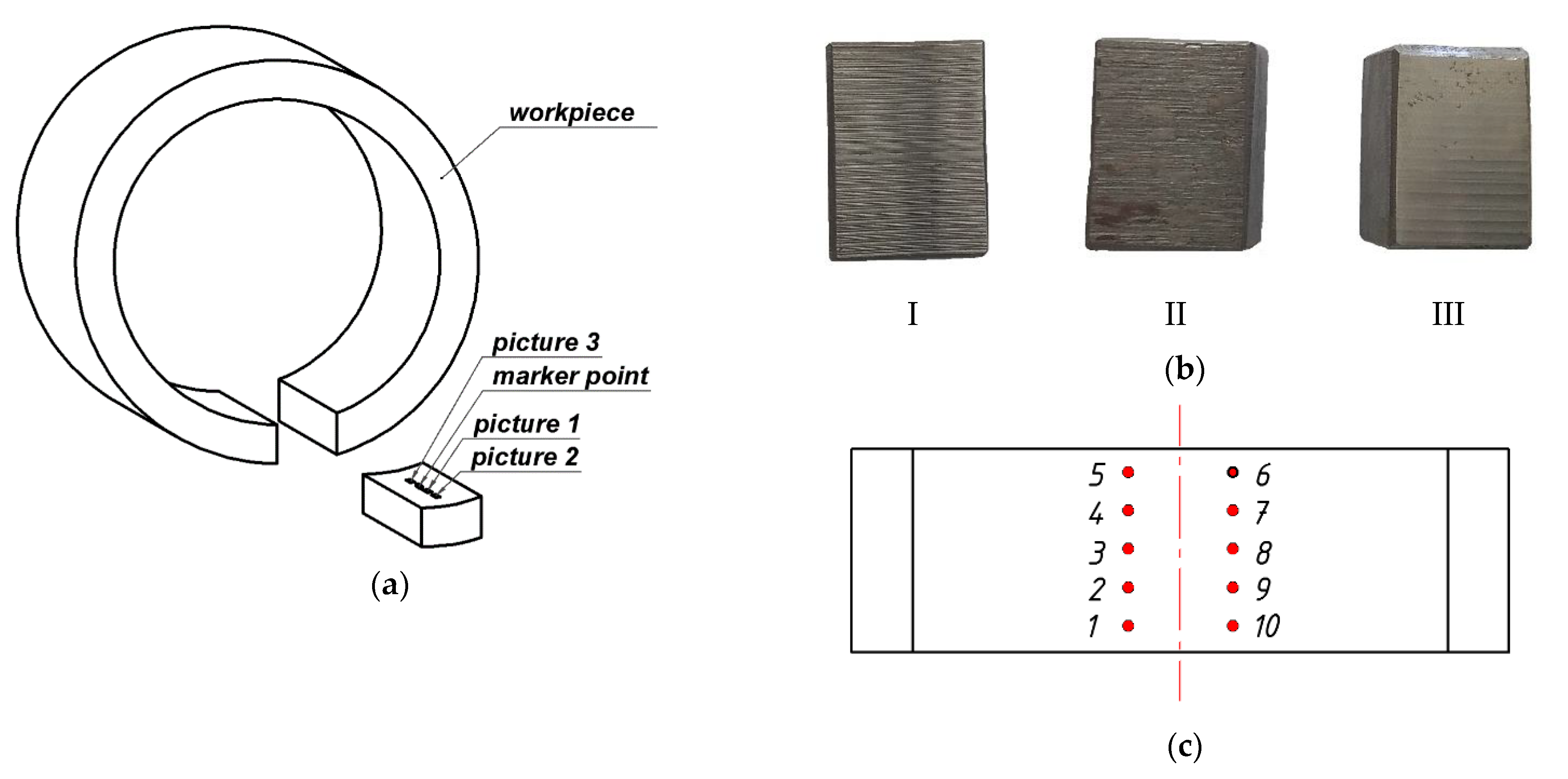
3. Objects and Methods of Research
4. Manufacturing Technology Analysis
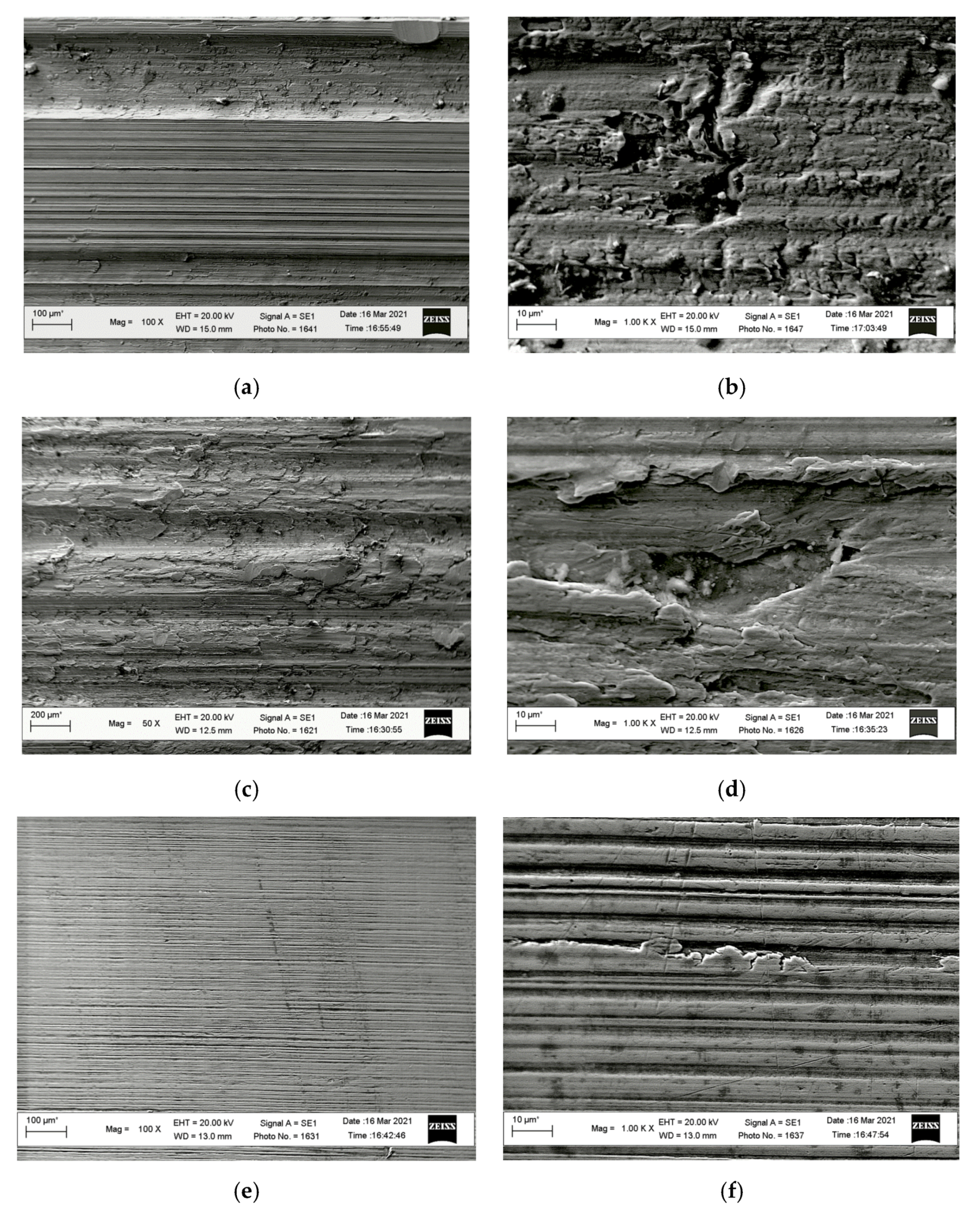
- Rough turning, Figure 4a, caused the formation of deep lines on the surface, which can be considered a consequence of intermittent cutting. The uneven surface relief was a negative factor caused by the vibration of the cutting tool, the workpiece, and machine parts. This reduced the workpiece surface quality.
- Semi-finishing resulted in the surface with a pronounced effect of plastic deformation. There were noticeable scaly tears on the surface. Their height indicated a low temperature in the treatment zone. This surface-forming mechanism also evidenced the cyclical interaction between the tool and the workpiece surface. Plastic deformation causes the strengthening of the surface layer and structural and mechanical heterogeneity of surface properties at the micro-level.
- Finishing occurred due to the tool and treated surface coming into contact by their roughness tops, the bearing area of which was small. The surface looked relatively smooth, covered with small unidirectional lines. This was due to significant pressures on the contact surface that exceeded the yield strength of the material and caused the intense plastic deformation of roughness, followed by its smoothing. In parallel, the contact area between the tool and the treated surface increased. Under such conditions, the surface layer of the metal was significantly strengthened, which increased the surface resistance to plastic deformation. Thus, the roughness value was stabilized.
5. 3-D Profilometry
6. Discussion of Findings
7. Conclusions
Author Contributions
Funding
Institutional Review Board Statement
Data Availability Statement
Conflicts of Interest
References
- Drogobych Truck Crane Plant. Available online: http://dak.com.ua/eshop/products_goup/4 (accessed on 1 May 2021).
- Zhang, X.; Wang, G.; Xia, P.; Li, H.-P.; He, M. Finite element analysis and experimental study on contact pressure of hydraulic support bud-shaped composite sealing ring. Adv. Mech. Eng. 2016, 8, 1–9. [Google Scholar] [CrossRef] [Green Version]
- Velichko, S.A.; Chumakov, P.V.; Kolomeychenko, A.V. Assessment of technical condition of C series power hydraulic cylinders of mounted hydraulic systems of tractors. Eng. Technol. Syst. 2019, 29, 397–413. [Google Scholar] [CrossRef]
- Castro, R.D.M.; Rocha, A.D.S.; Curi, E.I.M.; Peruch, F. A Comparison of microstructural, mechanical and tribological properties of WC-10Co4Cr—HVOF coating and hard chrome to use in hydraulic cylinders. Am. J. Mater. Sci. 2018, 8, 15–26. [Google Scholar] [CrossRef]
- Mrochek, Z.A.; Shaturov, H.F.; Zholobov, A.A.; Shaturov, D.H. Progressive methods of shaping the surfaces of hydraulic cylinders. Bull. BNTU 2009, 1, 14–18. (In Russian) [Google Scholar]
- Yang, L.; Moan, T. Prediction of long-term fatigue damage of a hydraulic cylinder of a wave energy converter subjected to internal fluid pressure induced by wave loads. Int. J. Mar. Energy 2013, 2, 43–60. [Google Scholar] [CrossRef]
- Gamez-Montero, P.J.; Salazar, E.; Castilla, R.; Freire, J.; Khamashta, M.; Codina, E. Friction effects on the load capacity of a column and a hydraulic cylinder. Int. J. Mech. Sci. 2009, 51, 141–151. [Google Scholar] [CrossRef]
- Qin, P.-P.; Yang, C.-L.; Huang, W.; Xu, G.-W.; Liu, C.-J. Honing process of hydraulic cylinder bore for remanufacturing. In Proceedings of the 2015 4th International Conference on Sensors, Measurement and Intelligent Materials, Shenzhen, China, 27–28 December 2015; Atlantis Press: Amsterdam, The Netherlands, 2016. [Google Scholar] [CrossRef]
- GOST 2789-73. Surface Roughness. Parameters and Characteristics; Standartinform, Publ.: Moscow, Russia, 2018; 6p. (In Russian) [Google Scholar]
- DSTU GOST 25142:2009. Surface Roughness. Terms and Definitions; Derzhspozhivstandart of Ukraine, Publ.: Kiev, Ukraine, 2009; 22p. (In Ukrainian) [Google Scholar]
- GOST R ISO 4287-2014. Geometrical Product Specifications (GPS). Surface Texture. Profile Method. Terms, Definitions and Surface Texture Parameters; Standartinform Publ.: Moscow, Russia, 2015; 18p. (In Russian) [Google Scholar]
- ISO 1302:2002 Geometrical Product Specifications (GPS)—Indication of Surface Texture in Technical Product Documentation. Available online: https://www.iso.org/obp/ui/#iso:std:iso:1302:ed-4:v1:en (accessed on 9 June 2021).
- ISO 13565-2:1996 Geometrical Product Specifications (GPS)—Surface Texture: Profile Method; Surfaces Having Stratified Functional Properties—Part 2: Height Characterization Using the Linear Material Ratio Curve. Available online: https://www.iso.org/standard/22280.html (accessed on 9 June 2021).
- GOST 16514-96. Hydraulic Fluid Power. Hydraulic Cylinders. General Technical Requirements; Izdatelstvo Standartov, Publ.: Minsk, Belarus, 2002. (In Russian) [Google Scholar]
- Witenberg, Y.R. Surface Roughness and Methods of Its Evaluation; Sydostroyeniye: Leningrad, Russia, 1971; 108p. [Google Scholar]
- Dobrotvorskyi, S.S.; Basova, E.V. Surface Roughness Prediction Methods: Overview. Bull. Natl. Tech. Univ. KhPI Themat. Issue Technol. Mech. Eng. 2010, 41, 23–45. (In Ukrainian) [Google Scholar]
- Xiao, M.; Shen, X.; Ma, Y.; Yang, F.; Gao, N.; Wei, W.; Wu, D. Prediction of Surface Roughness and Optimization of cutting parameters of stainless steel turning based on RSM. Math. Probl. Eng. 2018, 2018, 9051084. [Google Scholar] [CrossRef] [Green Version]
- Knight, W.A.; Boothroyd, G. Fundamentals of Metal Machining and Machine Tools, 3rd ed.; CRC Press: Boca Raton, FL, USA, 2005; 602p. [Google Scholar]
- Lin, S.C.; Chang, M.F. A study on the effects of vibrations on the surface finish using a surface topography simulation model for turning. Int. J. Mach. Tools Manuf. 1998, 38, 763–782. [Google Scholar] [CrossRef]
- Thomas, M.; Beauchamp, Y.; Youssef, A.Y.; Masounave, J. Effect of tool vibrations on surface roughness during lathe dry turning process. Comput. Ind. Eng. 1996, 31, 637–644. [Google Scholar] [CrossRef]
- Tabenkin, A.N.; Tarasov, S.B.; Stepanov, A.N. Sherokhovatost’, Volnistost’, Profil’. Mezhdunarodnyy Opyt [Roughness, Waviness, and Profile, International Experience]; Russian Federation, Izd-vo Politekhn. Un-ta: Saint Petersburg, Russian, 2007; 136p. (In Russian) [Google Scholar]
- Davidescu, D.A.; Pavelescu, D.; Tudor, A.; Seiciu, L.P. The importance of accuracy values of the abbottfirestone parameters curve for fractal and nonfractal calculus. In The Annals of University Dunărea de Jos of Galaţi-Fascicle VIII: Tribology; 2004; pp. 3–6. Available online: https://www.academia.edu/24590282/The_Importance_of_Accuracy_Values_of_the_Abbott_Firestone_Parameters_Curve_for_Fractal_and_Non_Fractal_Calculus (accessed on 9 June 2021).
- Salcedo, M.C.; Coral, I.B.; Ochoa, G.V. Characterization of surface topography with Abbott Firestone curve. Contemp. Eng. Sci. 2018, 11, 3397–3407. [Google Scholar] [CrossRef]
- Lipa, Z.; Tomaníčková, D. Utilisation of abbott-firestone curves characteristics for the determination of turned surface properties. Ann. Fac. Eng. Hunedoara-Int. J. Eng. 2011, 9, 223–226. [Google Scholar]
- Laheurte, R.; Darnis, P.; Darbois, N.; Cahuc, O.; Neauport, J. Subsurface damage distribution characterization of ground surfaces using Abbott–Firestone curves. Opt. Express 2012, 20, 13551–13559. [Google Scholar] [CrossRef] [PubMed] [Green Version]
- Amine, H. Effect of cutting variables on bearing area curve parameters (BAC-P) during hard turning process. Arch. Mech. Eng. 2020, 67, 73–95. [Google Scholar] [CrossRef]
- Kubatova, D.; Melichar, M. Roughness evaluation using Abbott-Firestone curve parameters. In Proceedings of the 29th International DAAAM Symposium, Zadar, Croatia, 24–27 October 2018; pp. 467–475. [Google Scholar] [CrossRef]
- Aftanaziv, I.S.; Kusyi, Y.M. Analysis and vibration of the optimal final operations of the technological process of preparing pre-built cylindrical parts. Bull. Lviv Polytech. Natl. Univ. 2000, 412, 3–11. [Google Scholar]
- Schneider, Y.G. Service Properties of Parts with Regular Microrelief, 2nd ed.; Mashinostroenie: Leningrad, Russia, 1982; 248p. (In Russian) [Google Scholar]
- Yamnikov, A.S.; Rodionova, E.N.; Matveev, I.A. Influence of technological inheritance on accuracy of assembly of axisymmetric shells. In Proceedings of the 6th International Conference on Industrial Engineering (ICIE 2020); Radionov, A.A., Gasiyarov, V.R., Eds.; Lecture Notes in Mechanical Engineering; Springer: Berlin/Heidelberg, Germany, 2021; pp. 130–140. [Google Scholar] [CrossRef]
- Kryvyi, P.D.; Dzyura, V.O.; Tymoshenko, N.M.; Krypa, V.V. Technological heredity and accuracy of the cross-section shapes of the hydro-cylinder cylindrical surfaces. In Proceedings of the International Conference on Materials and Processing and the 42nd North American Manufacturing Research Conference, Detroit, MI, USA, 9–13 June 2014; p. 2, Paper No. MSEC2014-3946. [Google Scholar] [CrossRef]
- Zhang, Y.; Zeng, L.; Wu, Z.; Ding, X.; Chen, K. Synergy of surface textures on a hydraulic cylinder piston. Micro Nano Lett. 2019, 14, 424–429. [Google Scholar] [CrossRef]
- Pawlus, P.; Reizer, R.; Wieczorowski, M.; Krolczyk, G. Material ratio curve as information on the state of surface topography—A review. Precis. Eng. 2020, 65, 240–258. [Google Scholar] [CrossRef]
- Dzyura, V.O.; Maruschak, P.O.; Zakiev, I.M.; Sorochak, A.P. Analysis of inner surface roughness parameters of load-carrying and support elements of mechanical systems, International. J. Eng. Trans. B Appl. 2017, 30, 1170–1175. [Google Scholar] [CrossRef]
- Konovalov, S.; Ivanov, Y.; Gromov, V.; Panchenko, I. Fatigue-induced evolution of AISI 310S steel microstructure after electron beam treatment. Materials 2020, 13, 4567. [Google Scholar] [CrossRef] [PubMed]


| Fault Type | Fault Reason | Consequences |
|---|---|---|
| Deviation of microgeometry and surface roughness | Non-optimal working surface roughness | An increase in friction coefficient, the occurrence of excessive longitudinal and transverse loads, increase in wear intensity. |
| Non-optimal working surface geometry | Increase in wear intensity and rapid wear, impaired load-bearing and sealing properties. | |
| In-service and kinematic damage | Imperfect guide insulation due to contamination | Increase in friction coefficient between the rod and the cylinder liner. |
| Imperfect lubrication of friction surfaces | Increased friction force and elastic deformations outside the friction zone. In reverse motion, this changes the distribution of contact loads and causes additional plastic deformation of the contact zone. | |
| Very frequent stops and reversals | Increased contact shear deformations in the contact zone, which causes structural degradation of the liner material. | |
| Significant differences in the operational value of the rod projection | Increased degradation of the cylinder liner material, accumulation of micro- and macrodefects in the surface layer, which causes the activation of diffusion, adsorption, and chemisorption interaction of the friction surface. | |
| Force factors | Misalignment between a rod and a liner owing to an increased number of backlashes in the “liner-rod” system | Deflections/shears in the “liner-rod” system. |
| Rod distortions (technological distortions). | Misalignment of the “liner-rod” system, which leads to plastic deformations accumulated in the liner and rod walls, followed by jamming of the rod. |
| Hydrocylinder | Piston Diameter, mm | Rod Diameter, mm | Piston Stroke, mm | Max. Pressure in the Hydraulic System, MPa | Weight, kg |
|---|---|---|---|---|---|
| KS-4574.63.900-03.00 | 100 | 80 | 6000 | 25 | 411.8 |
| Operation No. | Groups of Technological Operations | Number of Transitions | Inner Diameter D, mm | Surface Roughness According to Technical Documentation Ra, μm | Location 1 | Location 2 | Location 3 | Average |
|---|---|---|---|---|---|---|---|---|
| 1 | Roughing | 1 | Ø94H11 | 20 | ||||
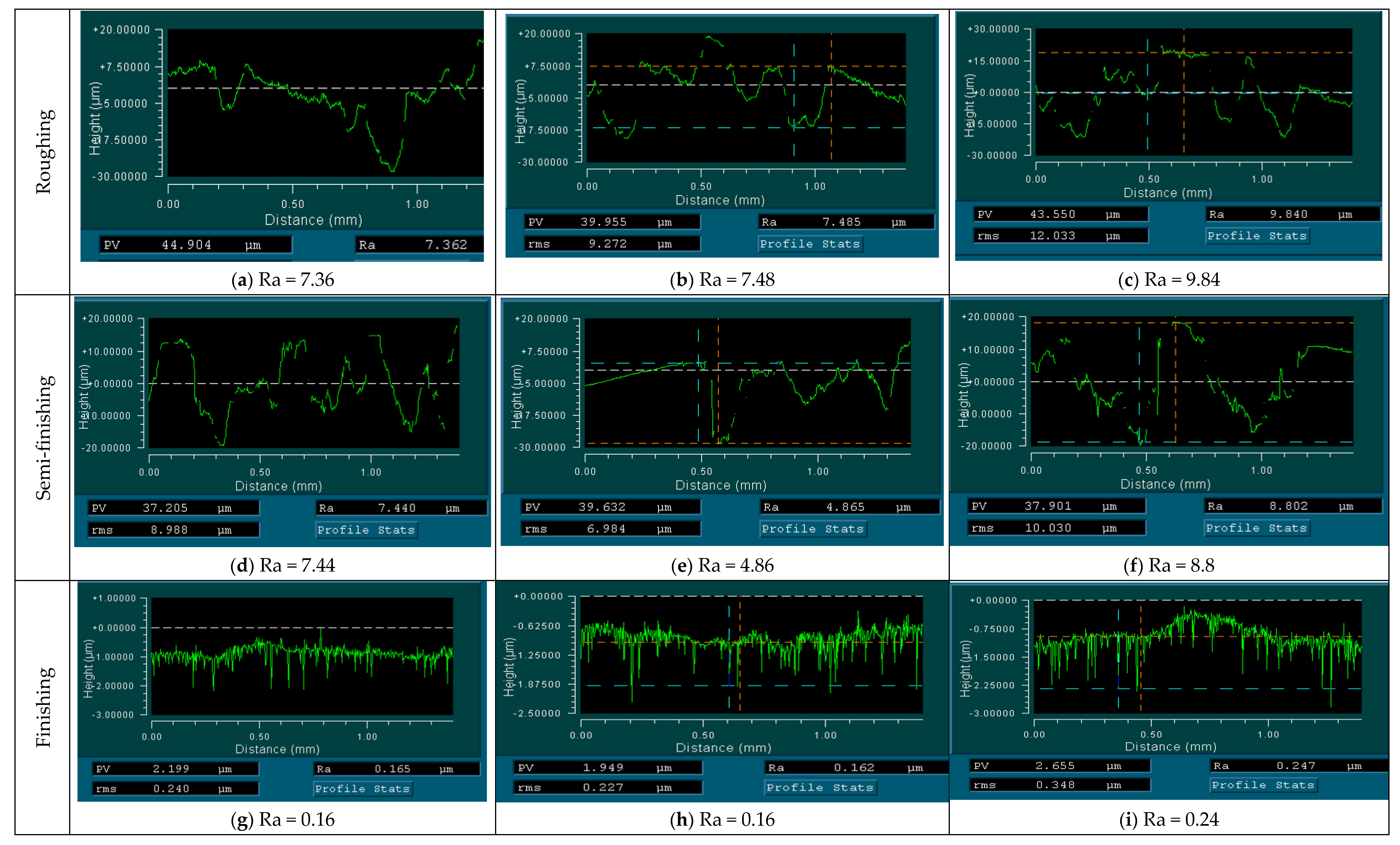
| 2 | 1 | Ø98.3H11 | 10 | 7.36 | 7.48 | 9.84 | 8.22 | |
| 3 | Semi-finishing | 1 | Ø99.3H11 | 5 | ||||
| 4 | 1 | Ø99.5H11 | 5 | 7.44 | 4.86 | 8.8 | 7.03 | |
| 5 | Finishing | 1 | Ø100H9 | 0.32 | 0.16 | 0.16 | 0.24 | 0.18 |
| Operation No. | Groups of Technological Operations | Inner Diameter D, mm |
Hardness Value, HRB for 10 Measurements | |||||||||
|---|---|---|---|---|---|---|---|---|---|---|---|---|
| 1 | 2 | 3 | 4 | 5 | 6 | 7 | 8 | 9 | 10 | |||
| 2 | Roughing | Ø98.3H11 | 77 | 80 | 77 | 78 | 70 | 77 | 81 | 77.5 | 79.5 | 85.0 |
| 4 | Semi-finishing | Ø99.5H11 | 80 | 75 | 77 | 76.5 | 77 | 83 | 85.5 | 75.5 | 82.5 | 83.0 |
| 5 | Finishing | Ø100H9 | 91.5 | 94.0 | 95.0 | 94.0 | 94.5 | 93.5 | 94.5 | 91.5 | 93.5 | 94.5 |
Publisher’s Note: MDPI stays neutral with regard to jurisdictional claims in published maps and institutional affiliations. |
© 2021 by the authors. Licensee MDPI, Basel, Switzerland. This article is an open access article distributed under the terms and conditions of the Creative Commons Attribution (CC BY) license (https://creativecommons.org/licenses/by/4.0/).
Share and Cite
Dzyura, V.; Maruschak, P. Optimizing the Formation of Hydraulic Cylinder Surfaces, Taking into Account Their Microrelief Topography Analyzed during Different Operations. Machines 2021, 9, 116. https://doi.org/10.3390/machines9060116
Dzyura V, Maruschak P. Optimizing the Formation of Hydraulic Cylinder Surfaces, Taking into Account Their Microrelief Topography Analyzed during Different Operations. Machines. 2021; 9(6):116. https://doi.org/10.3390/machines9060116
Chicago/Turabian StyleDzyura, Volodymyr, and Pavlo Maruschak. 2021. "Optimizing the Formation of Hydraulic Cylinder Surfaces, Taking into Account Their Microrelief Topography Analyzed during Different Operations" Machines 9, no. 6: 116. https://doi.org/10.3390/machines9060116