Article

Investigation on the Surface Quality Obtained during Trochoidal Milling of 6082 Aluminum Alloy

by
Nikolaos E. Karkalos
1,
Panagiotis Karmiris-Obratański
1,2,
Szymon Kurpiel
2,
Krzysztof Zagórski
2 and
Angelos P. Markopoulos
1,*
1
School of Mechanical Engineering—Laboratory of Manufacturing Technology, National Technical University of Athens, 15780 Athens, Greece
2
Faculty of Mechanical Engineering and Robotics—Department of Manufacturing Systems, AGH University of Science and Technology, 30-059 Cracow, Poland
*
Author to whom correspondence should be addressed.
Machines 2021, 9(4), 75; https://doi.org/10.3390/machines9040075
Submission received: 23 February 2021 / Revised: 20 March 2021 / Accepted: 29 March 2021 / Published: 30 March 2021

Abstract

:
Surface quality has always been an important goal in the manufacturing industry, as it is not only related to the achievement of appropriate geometrical tolerances but also plays an important role in the tribological behavior of the surface as well as its resistance to fatigue and corrosion. Usually, in order to achieve sufficiently high surface quality, process parameters, such as cutting speed and feed, are regulated or special types of cutting tools are used. In the present work, an alternative strategy for slot milling is adopted, namely, trochoidal milling, which employs a more complex trajectory for the cutting tool. Two series of experiments were initially conducted with traditional and trochoidal milling under various feed and cutting speed values in order to evaluate the capabilities of trochoidal milling. The findings showed a clear difference between the two milling strategies, and it was shown that the trochoidal milling strategy is able to provide superior surface quality when the appropriate process parameters are also chosen. Finally, the effect of the depth of cut, coolant and trochoidal stepover on surface roughness during trochoidal milling was also investigated, and it was found that lower depths of cut, the use of coolant and low values of trochoidal stepover can lead to a considerable decrease in surface roughness.

1. Introduction

Modern Computer-Aided Manufacturing (CAM) systems have experienced a significant development in recent years. CAM programs can essentially provide technologists with new machining strategies able to improve both productivity and surface quality obtained during machining [1,2,3,4,5]. Specifically, achieving the appropriate levels of surface quality and integrity is essential for mechanical parts not only in terms of dimensional accuracy but also in terms of acceptable hardness, residual stresses and fatigue strength values [6]. Among the most promising machining strategies, an innovative machining technology for slot milling is called trochoidal milling. The name of the trochoidal milling strategy comes from the shape of the trochoid tool path of the cutting tool center. The trochoid curve is a plane curve drawn by a point lying on the radius of a circle running on the inside (hypotrochoid and hypocycloid) or outside (epitrochoid and epicycloid) of a second circle. Therefore, trochoidal milling can be described as circular milling with the simultaneous forward movement of the tool. It is a method that is mainly used for milling grooves, recesses and closed pockets [7].
In the relevant literature, several researchers have investigated various aspects of trochoidal milling. For example, Rauch et al. [8] studied the influence of the trochoidal parameter selection and the tool path implementation on CNC machine tools. The experimental results revealed that in order to avoid harmful vibrations that have an impact on machining accuracy and tool life, high-level tool path formats, such as Splines, need to be avoided. Ibaraki, Yamaji and Matsubara [9] presented a tool path strategy for 2.5-dimensional high-speed trochoidal grooving. They proposed that material in medial areas should be removed by trochoidal grooving in order to control the machining load productively. A novel trochoidal tool path method of avoiding short increments in maximum radial depth cut by using multiple diameter tools was presented by Ferreira and Ochoa [10]. In other words, trochoidal milling was found to be able to protect the tool’s life by decreasing the load variation, and larger feed rates may be used.
Based on the radial depth of cut, Zhang et al. [11] tried to predict the cutting forces during trochoidal milling by considering the shape material and the tool’s dynamic characteristics. Although Wu et al. [12] proposed a similar prediction model to optimize high-speed trochoidal milling, the conclusions were not favorable regarding the tool life expansion and the cutting force regulation. By applying the trochoidal milling as an alternative machining approach, Petla et al. [13,14] found that the tool life is increased, and the overall cutting force magnitude is decreased in comparison to usual end milling of aluminum alloy 7075. The results showed substantial differences by matching the feed rate and the tool speed, between the trochoidal and slotting strategies. These differences were reduced when slotting parameters were used based on trochoidal milling conditions.
As traditional trochoidal circular milling is more time consuming, Li, Xu and Tang [15] proposed a new type of trochoidal pattern capable of machining complex slots and curved geometries. The results show that the critical element of determining the cutting forces and the heat dissipation is the maximum engagement angle between the workpiece and the tool. Oh et al. [16] combined Laser-Assisted Machining (LAM) with trochoidal milling of titanium grade 5. The primary and most significant conclusions were found when a laser locally preheated the material; the cutting force was reduced from 33 to 41%, and the cutting energy was decreased up to 41%. In the study of Zagórski et al. [17], the influence of the trochoidal cutting speed and step on the machining parameters, such as the cutting force and vibration, which affects the surface roughness of the AZ31D, and AZ31 magnesium alloys were analyzed. The presented analysis showed that an increase in cutting speed up to 1200 m/min leads to more stable machining conditions; specifically, lower values of vibrations and cutting forces resulted in a 50% decrease in the 3D surface roughness. Santhakumar and Mohammed Iqbal [18] aimed to determine the optimum process parameters during the trochoidal milling of AISI D3 steel in order to achieve the lowest possible surface roughness and maximum dish angle. Their results indicated that the achievement of both goals was possible under high cutting speed, low feed rate and low trochoidal stepover values. Volosova et al. [19] focused on the effect of tool coating on the wear resistance of the cutting tool during the trochoidal milling of titanium alloy. The cutting tool with the CrTiN-AlTiN-AlTiCrN/SiN coating exhibited the lowest wear rate and thus higher operating time. Šajgalík et al. [20] investigated the parameters of trochoidal motion, namely, trochoidal stepover and engagement angle, on the machining forces during the milling of hardened steel. It was concluded that an increase in both parameters resulted in a considerable increase in the resultant cutting force.
Deng et al. [21] conducted a comparative study regarding the cutter edge temperature prediction between trochoidal and slide milling. Their results confirmed the lower temperature in trochoidal milling, compared with this in inside milling. Moreover, the study demonstrated that thermal shock is very low in trochoidal milling. Thus, according to these two factors together, trochoidal milling is more suitable for difficult-to-cut materials, while the tool life is extended. Based on the inscribed ellipse and transformation of medial axis, a 12.7% more efficient trochoidal method was proposed by Huang et al. [22] without increasing the cutting force. This method can achieve a higher Material Removal Rate (MRR) and shorter milling lengths based on the transformation of the inscribed circle to an inscribed ellipse. Finally, in contrast to other studies, Gross et al. [23] presented a comparison study between trochoidal and linear milling in terms of vibration behavior. The generated vibrations during the trochoidal machining of different materials and geometrical patterns, including bores of different diameters and grooves with different wall thicknesses, resulted in higher wear phenomena. Thus, according to the presented results, the authors concluded that trochoidal milling is not a suitable method for reducing tool wear and vibrations compared to linear milling, at least for the cases investigated.
The aim of the current paper is to investigate the effect of the trochoidal milling strategy on the surface roughness of the machined workpiece, something that has not yet been thoroughly studied. For this reason, an experimental comparative study on the surface quality between the traditional and trochoidal milling of aluminum alloy 6082 was conducted under different cutting speed and feed conditions. After the experiments were conducted, various surface roughness indicators, such as Ra, Rz, Rsk and Rku, were measured according to the ISO 25178-2, and the effect of the process parameters and milling strategy on them was analyzed and discussed. Finally, the effect of depth of cut, coolant and trochoidal stepover on surface roughness was also investigated for the case of trochoidal milling.

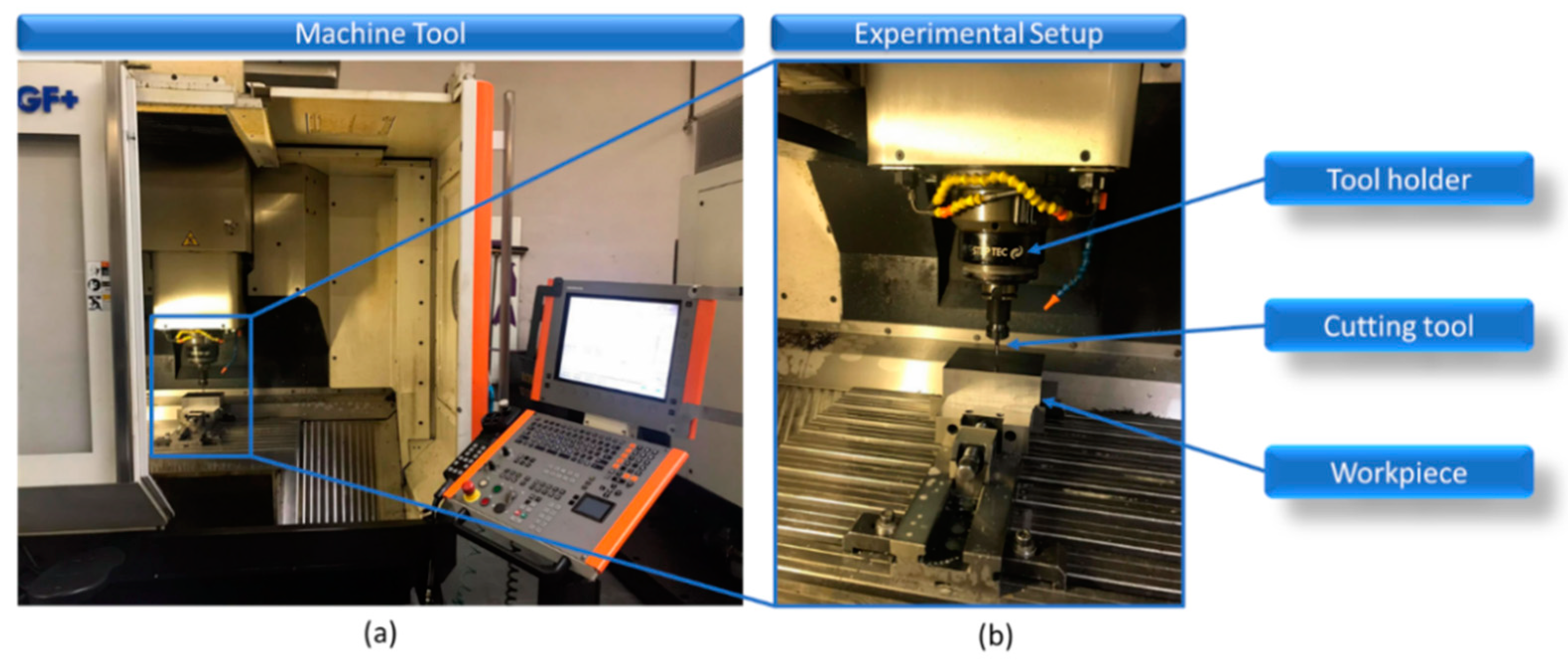
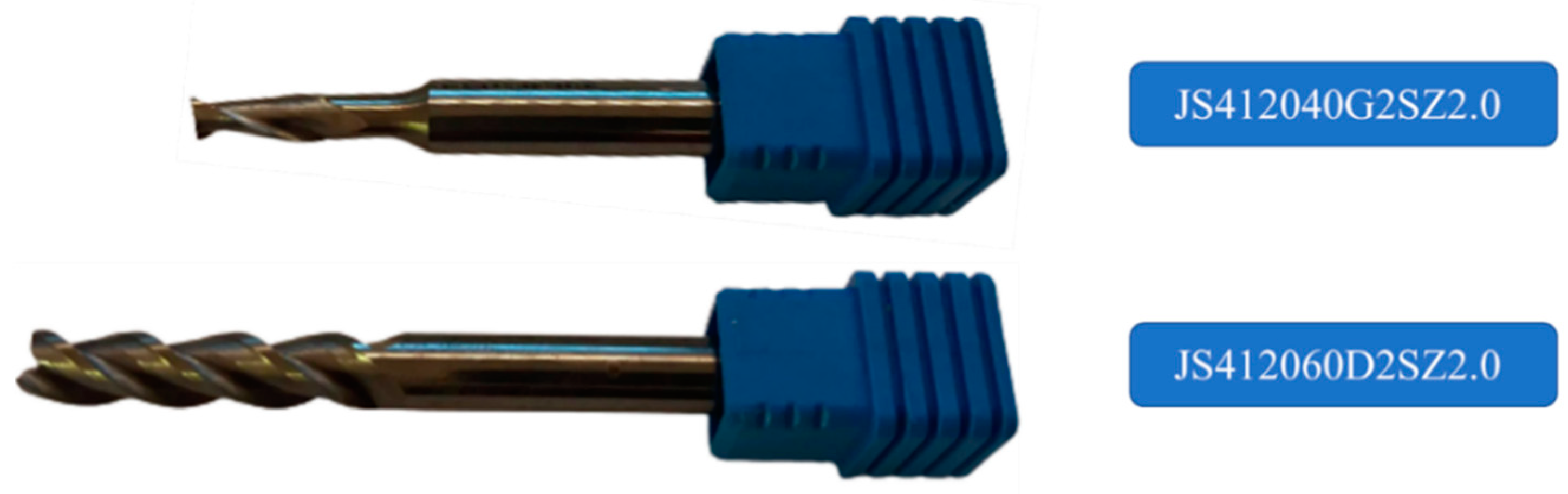
2. Materials and Methods

In the present work, two series of experiments were carried out in order to determine the effect of the trochoidal milling strategy on the surface roughness of slots cut on an aluminum alloy workpiece. More specifically, the first series of experiments consisted of 10 full factorial experiments conducted under different feed and cutting speed values. The second series of experiments consisted of 10 full factorial experiments of traditional slot milling under the same feed and cutting speed values in order to be compared to the trochoidal milling experiments. The process parameter values for both cases of experiments are presented in Table 1. All process parameters were chosen in accordance with established recommendations for trochoidal milling: the depth of cut (ap) is lower than twice the diameter of the end mill (0.8 mm < 8 mm), the trochoidal step is below 10% of the diameter of the end mill (0.3 mm < 0.4 mm) and the diameter of the chosen end mill is below 70% of the width of the slot (4 mm < 4.2 mm). Finally, three additional series of experiments were conducted for trochoidal milling cases with different depths of cut, use of coolant and use of different trochoidal step values, both below and over the aforementioned limit.
The experiments of trochoidal and traditional milling were conducted on a Micron HPN 600 HD (GF Machining Solutions, Switzerland) three-axis CNC machining center equipped with an iTNC digital control system made by Heidenhain. This high-performance machining center, shown in Figure 1, is equipped with an HSK-A63 working spindle. The first and second series of experiments were conducted under dry machining conditions.
The material used in this study is a medium-strength hardened AA 6082. This aluminum alloy has excellent corrosion resistance and plastic properties during annealing after hardening [24]. Table 2 shows the chemical composition of the workpiece. Aluminum 6082 is suitable for specific technological applications with a long service life in temperatures between −50 and 70 °C. This is usually used in contact with food and the production of high-performance aircraft and car components. This alloy is used, inter alia, in machine building, single-purpose machine structures, shipbuilding techniques, simple welded structures, transport machines, floor coverings, flight cabins, helicopter cockpits, and safety barriers, escalators, furniture, rivet shafts, lifts and columns.
For the milling tests, a 4 mm diameter endmill was used for the trochoidal milling and a 6 mm for the traditional milling. Both tools are made from SECO (Fagersta, Sweden), and they belong to the Jabro-Solid² product family. The following Figure 2 shows the uncoated solid carbide end mills suitable for general applications and offering cost efficiency, speed and flexibility. These tools are suitable for general machining, including non-ferrous materials, such as aluminum; they have relatively long cutting lengths and thin cores with two flutes, 30° flute helix angle and 0° lead angle, whereas the maximum depth of cut is 8.0 mm for the 4 mm diameter end mill and 12.0 mm for the 6 mm diameter end mill.
Surface roughness (SR) was measured and evaluated with a TOPO 01P (IOS, Cracow, Poland) contact profilometer equipped with an induction head with a 90° apex angle cone tip. According to the ISO 25178-2, a random machined surface in the slot’s center was chosen. The scanned surface area was 1.25 mm long and 3 mm wide, consisting of 31 consecutive roots with 0.5 mm/s scanning speed. As the above norm suggests, a gaussian filter was employed based on the Fourier transformation, and the cutt-off lengths were defined. Thus, an 8 mm cutting length and a 2.5l s filter were used. Several useful surface roughness indicators were recorded during the measurements, such as Ra, Rz, Rku, Rsk, in order to evaluate surface quality obtained by different process conditions and milling strategies.

3. Results and Discussion

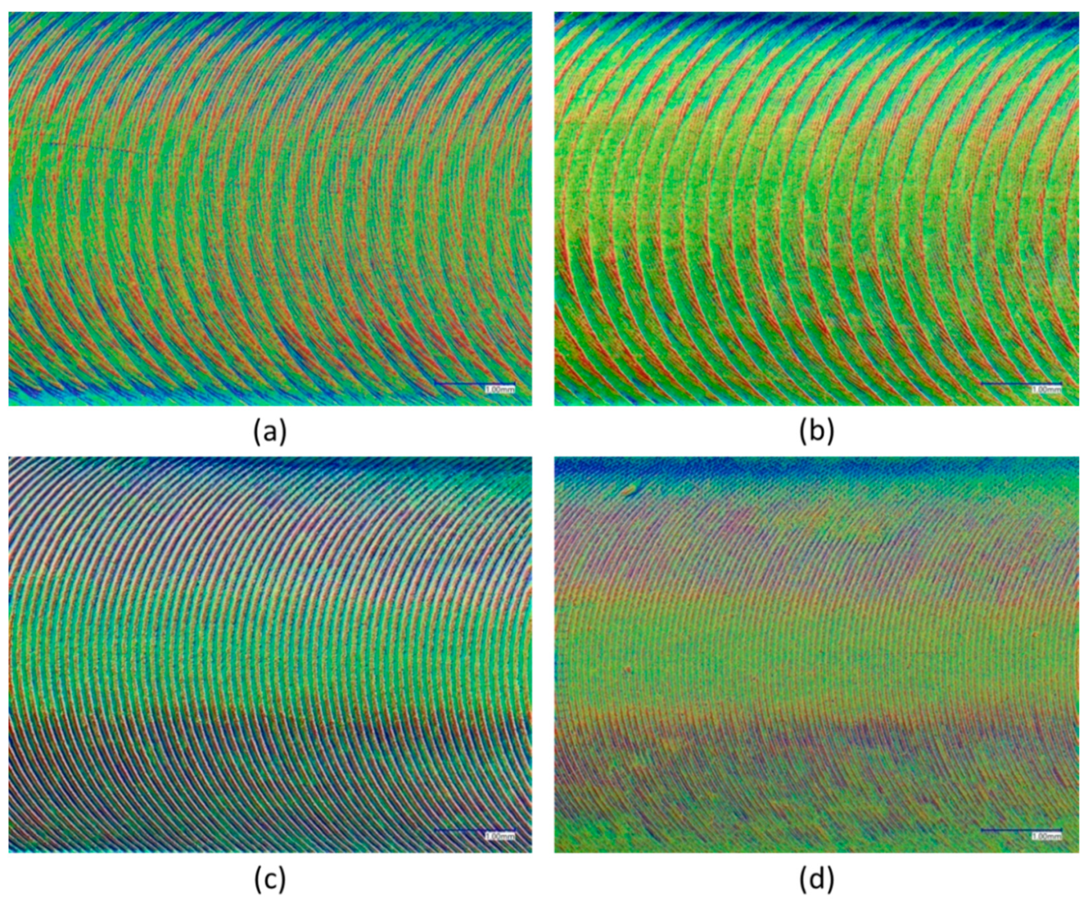
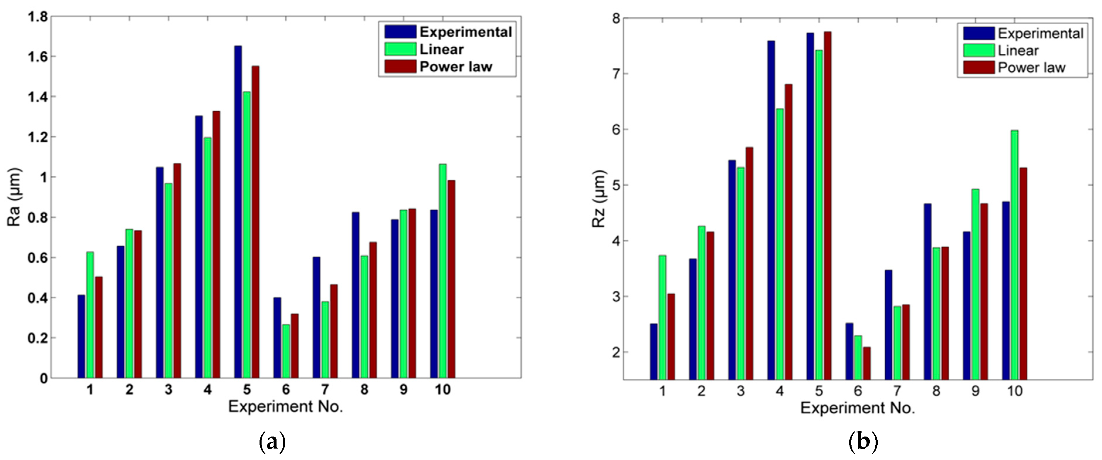
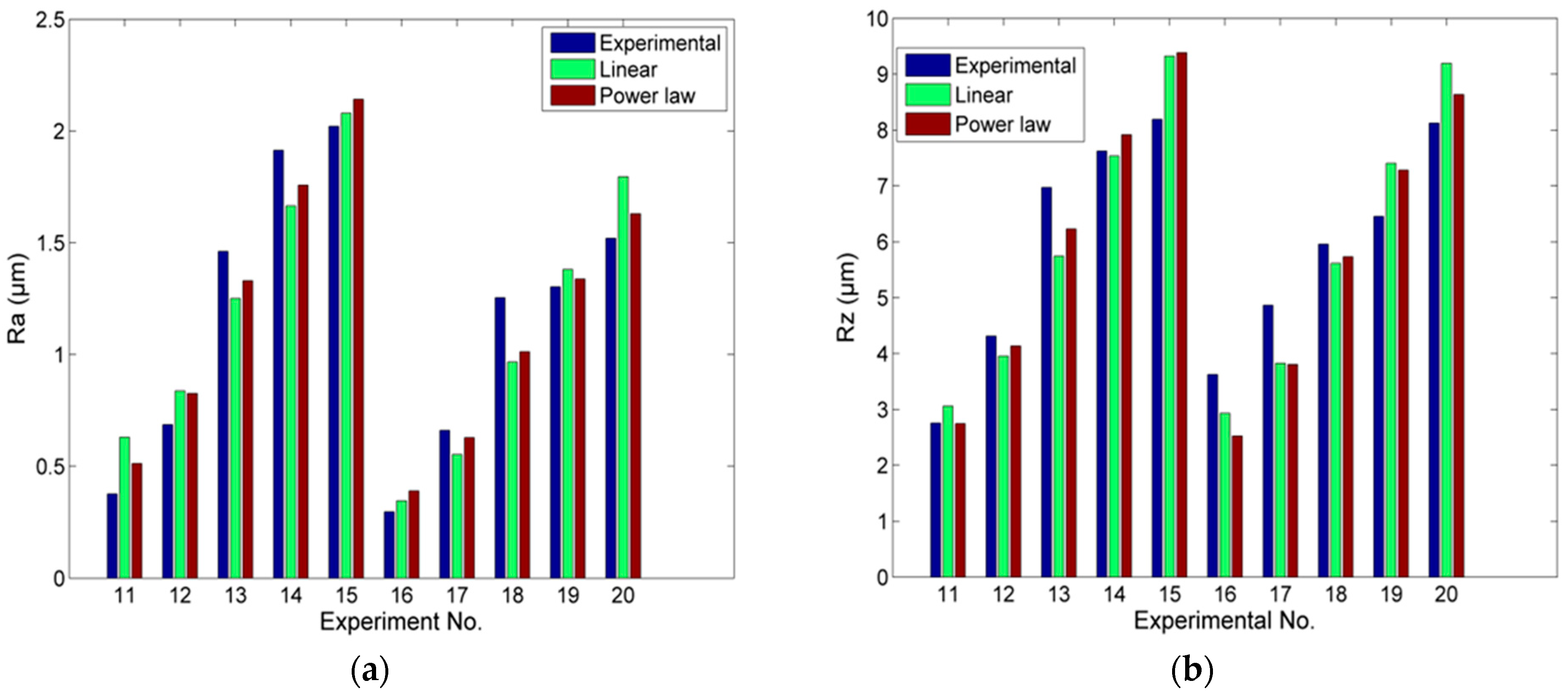
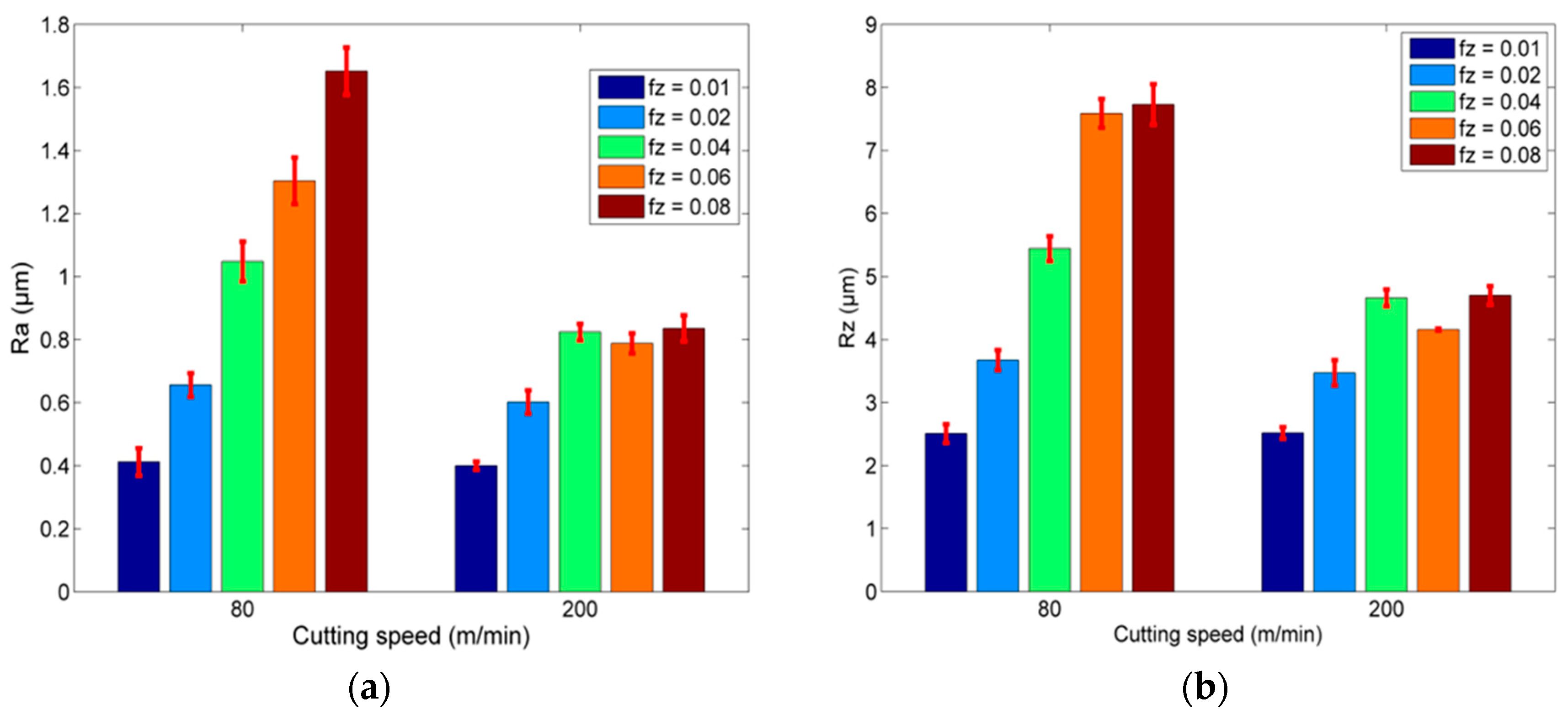
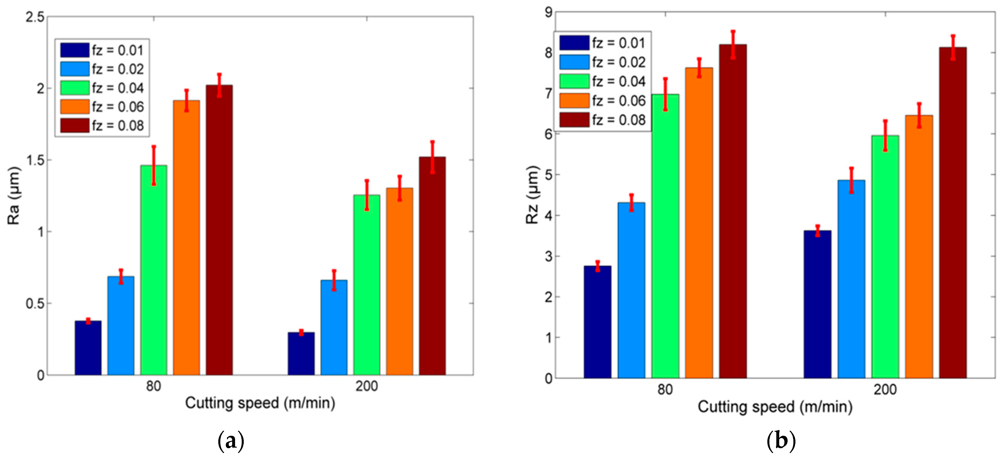
3.1. Experimental Results Regarding Ra and Rz

After the experiments were conducted, results regarding the surface roughness of the machined workpiece surfaces were obtained. The results regarding Ra and Rz in each case are presented in Table 3. From the experimental results, it can be seen that there is a considerable deviation of surface roughness with varying process parameters, especially the feed and milling strategy, with the lowest value being 0.297 μm and the highest being 2.021 μm. Similarly, the values of Rz vary in the range of 2.508–8.194 μm. Thus, it can be seen that the selection of suitable process parameters can improve the surface quality considerably, given that it does not severely affect the productivity.
In order to more closely observe the differences between the surfaces obtained by trochoidal and traditional slot milling strategies, various characteristic images from milled slots were obtained through an optical microscope and are depicted in Figure 3.
The typical marks forming a trochoidal curve on the workpiece surface in the case of traditional slot milling are obvious in Figure 3c,d. In these cases, the path of each cutting edge is described by the following parametric equations, representing the simultaneous rotational and translational movement of the tool tip (denoted as tt):
xtrad,tt(t) = Rtoolcos(ω1t) + vft
ytrad,tt(t) = Rtoolsin(ω1t)
where Rtool is the radius of the cutting tool, vf is the feed rate equal to N × z × fz, N is the spindle speed, z the number of flutes of the cutting tool and ω1 is the angular speed of the cutting tool.
On the other hand, the marks observed on the workpiece surfaces, which were machined by trochoidal slot milling, are different from the previous ones. In these cases, in addition to the general trochoidal curves, other curves are superimposed on them as well, occurring from the complex path of the tool tip, and thus, in Figure 3a,b, the clear trochoidal curve marks seem “disturbed” by an additional superimposed pattern of marks. In the case of trochoidal milling, the tool center (denoted as tc) moves in a trochoidal curve, described by the following parametric equations [25,26]:
x troch , tc ( t ) = R tc cos ( ω 2 t ) + P troch 2 π ω 2 t
ytroch,tc(t) = Rtcsin(ω2t)
where Rtc is the trochoidal radius, and ω2 is the angular speed of the trochoidal movement of the cutting tool center. In order to define a constant feed rate, equal to vf, the ω2 angular speed should be variable [26]. As there is no analytical solution for the determination of ω2, it can be approximated in terms of vf and Ltroch, which represent the length of the trochoidal path for one revolution [26]:
ω 2 = 2 π v f L troch
However, the tool tip also moves according to the rotational motion of the cutting tool as well; thus, the final equations for the movement of the tool tip include terms relevant to three different motions, two rotational and one translational, in the direction of the trochoidal step. The additional rotational motion due to the trochoidal path of the tool center, which is essentially the speed at which the tool traverses the trochoidal arc, is called nutation [14,27], and the respective angular speed ω2 is also called the nutation rate. The trajectory of the tool tip in this case is given by the following parametric equations [14,27,28]:
xtroch, tt = Rtccos(ω2t) + Rttcos(ω1t) + vft
ytroch,tt = Rtcsin(ω2t) + Rttsin(ω1t)
Based on the experimental results, regression models can be developed in order to describe the correlation between surface roughness and the process parameters in both series of experiments. In order to select the most suitable model, a comparison between linear and non-linear regression models for Ra and Rz values was conducted. Given that only two process parameters are used as input variables, it was chosen that the regression function should be as simple as possible, namely, a first order linear model and a simple power law model.
The obtained linear and non-linear regression models for Ra and Rz in the case of trochoidal milling are given in the form of Equations (8) and (9), respectively:
Ra = 0.752 − 0.003vc + 11.400fz
Rz = 4.167 − 0.012vc + 52.700fz
The R2 values for the two equations were 0.8047 and 0.7788, respectively, which are not acceptable values, as the variance of the responses for which the model does not account for is relatively high. Thus, non-linear regression models are created based on a power law function:
Ra = 53.934vc−0.498fz0.541
Rz = 147.158vc−0.413fz0.449
When the power law models are considered, the R2 values are 0.9648 and 0.9028. From these results, it can be concluded that the predicted values from the power law models model are significantly closer to the experimental ones than the results using the linear model. Thus, the power law model can be used in order to predict the expected surface roughness values with low computational cost and high accuracy. This observation is directly related to the results displayed in Figure 4, as in most cases, the predicted Ra and Rz values from the power law model are closer to the experimental ones than in the ones obtained from the linear model.
The same investigation was conducted regarding the traditional slot milling experiments. The derived linear and power law models are presented in Equations (12)–(13) and (14)–(15), respectively:
Ra = 0.613 − 0.002vc + 20.700fz
Rz = 2.250 − 0.001vc + 89.500fz
Ra = 44.821 ∗ vc−0.298fz0.687
Rz = 62.224 ∗ vc−0.091fz0.591
In these cases, the difference between the linear and power law models is less significant, as in the case of Ra, the R2 values are 0.889 and 0.949, respectively, and in the case of Rz, 0.862 and 0.905, respectively. Thus, also in this case, the power law model is clearly superior to the linear one. These findings have an obvious relation with the results displayed in Figure 5, as the results obtained with the power law model are usually closer to the experimental ones than those obtained with the linear model.
In order to determine which milling strategy is the most favorable and under which conditions, a comparison between surface roughness values obtained from each strategy was conducted. From the results displayed in Figure 6a,b, it can be seen that the Ra values increase with an increase in feed rate in any case, as it was anticipated. The increase is higher in the cases with the lowest cutting speed, as the Ra value increases almost four times when fz increases by a factor of 8, whereas the increase in surface roughness in the cases with the highest cutting speed is only almost twofold for the same increase in fz. Similar results are observed in the case of Rz, as its values increased with an increase in fz, but the increase was significantly lower in the cases with the higher cutting speed. However, regarding both Ra and Rz, it can be observed that in the cases with a cutting speed of 200 m/min, the surface roughness values remain almost constant above an fz value of 0.04 mm/tooth.
Moreover, in most cases, the increase in cutting speed from 80 to 200 m/min leads to a decrease in surface roughness indicator values, but the difference of surface roughness values as cutting speed increases becomes larger for fz values over 0.02 mm/tooth.
In the case of traditional milling, the Ra and Rz values in respect to feed and cutting speed values are depicted in Figure 7a,b, respectively. In these cases, a slightly different behavior is observed, as the increase in Ra values with increased fz values is clearer in comparison to the trochoidal milling. Moreover, the surface roughness values decrease almost in every case with a higher cutting speed. For Rz, similar trends are observed. Regarding the comparison between the trochoidal milling strategy and traditional slot milling, it can be seen from Figure 7a,b that in most cases, especially for fz values over 0.01 mm/tooth, the surface roughness values obtained from trochoidal milling are lower than the values obtained from traditional milling, and the difference between them increases considerably with increasing fz. Thus, it is confirmed that, from the perspective of surface quality, the trochoidal milling strategy enables the use of higher feeds and cutting speeds, increasing the productivity of the process.

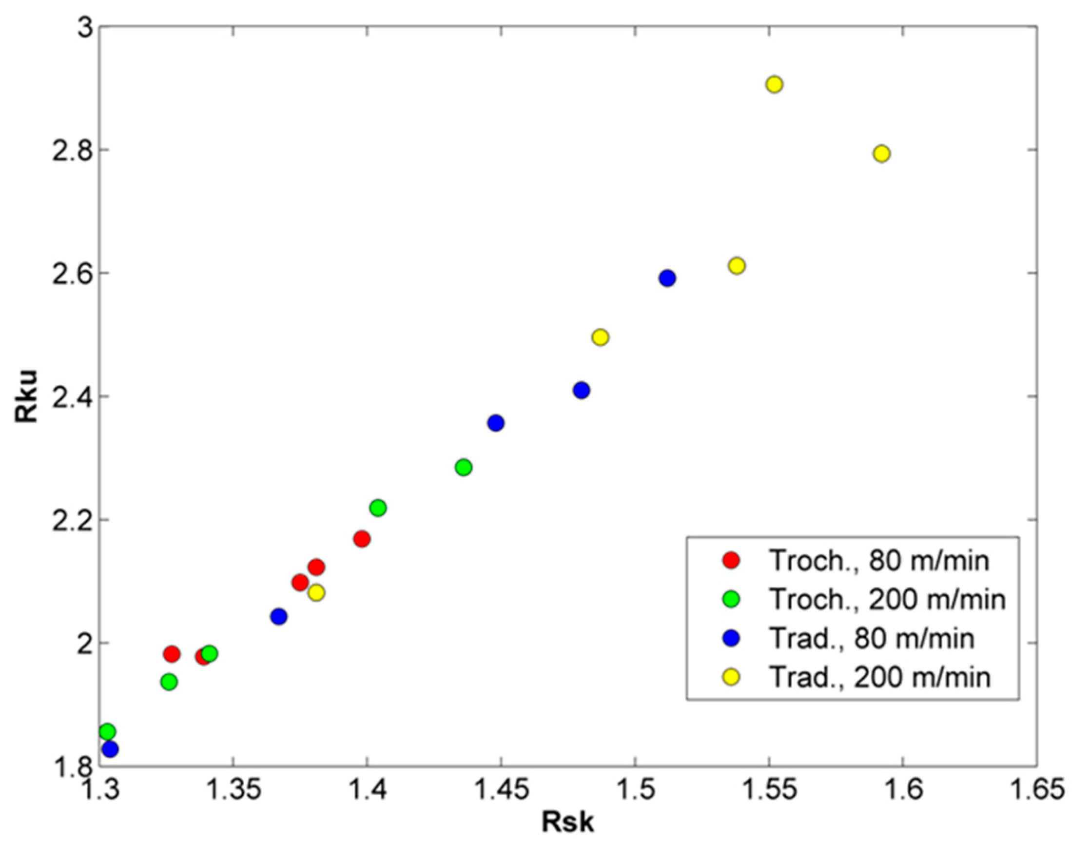
3.2. Experimental Results Regarding Skewness and Kurtosis of Surface Roughness Profile

In addition to the Ra and Rz surface roughness indicators, which are usually employed in similar studies [29], other roughness indicators can provide useful information regarding the properties of the machined surface [29,30,31]. Two of these parameters are skewness and kurtosis, which are surface roughness indicators related to the variations in the shape of the surface roughness profile.
Skewness (Rsk) values indicate the bias of the shape of the roughness profile, and it is calculated as the third normalized central moment of the probability density function (PDF) p(z) of the height distribution of the surface roughness profile z [32]:
Rsk = 1 σ 3 + z 3 p ( z ) dz
From its definition, it can be deduced that skewness is related to the first derivative of the surface and subsequently its deviation from symmetry [30]. A negative value of Rsk is related to height distribution, which is skewed above the mean line with deep scratches (valleys) and a lack of peaks; a skewness value of 0 is related to an ideal situation where the height distribution, i.e., peaks and valleys, are symmetrically distributed around the mean line, and a positive value indicates a surface with high peaks (asperities) or filled valleys [29,30].
Kurtosis (Rku) indicates the sharpness or bluntness of the roughness profile. It is calculated as the fourth normalized central moment of the PDF of height distribution by the following formula [32]:
Rku = 1 σ 4 z 4 p ( z ) dz
Regarding the Rku values, a value of Rku < 3 indicates a height distribution, which is skewed above the mean line with mostly low peaks and low valleys, a value of Rku = 3 indicates an ideal normal distribution of height with equal representation of sharp and indented areas, and a Rku value over three indicated a height distribution with many high peaks [30].
By investigating the values of Rsk and Rku, it is possible to extract various important details about the properties of the machined surfaces. For example, it has been shown that maximum contact pressure increases with an increase in skewness and kurtosis as well as load bearing ratio [29]. Moreover, surfaces with higher values of Rku and highly negative Rsk lead to a lower friction coefficient; negative Rsk also leads to higher fluid retention. This observation can be justified, as the combination of the values of these two parameters can lead to smoother surfaces with deep valleys and a more ordered surface. This type of surface can act as wear particle traps or microreservoirs which can improve lubrication [29]. However, surfaces with higher skewness values exhibit higher corrosion resistance [31].
Generally, it is not expected that a variation in process parameters can lead to a completely different type of roughness profile and the experimental results showed no evident trend with the variation of the two process parameters. Moreover, in all cases, Rku values were below three, and Rsk values were positive. In the relevant literature, it is more common to study the skewness and kurtosis of surface roughness in a common graph. Thus, in Figure 8, the results regarding kurtosis and skewness are depicted. It can be seen that a certain trend exists in the values of each milling strategy. The Rsk–Rku pairs in the case of traditional machining exhibit generally higher Rsk and Rku values as well as larger dispersion, thus indicating that the surfaces processed by traditional machining exhibit sharper profiles with higher peaks.

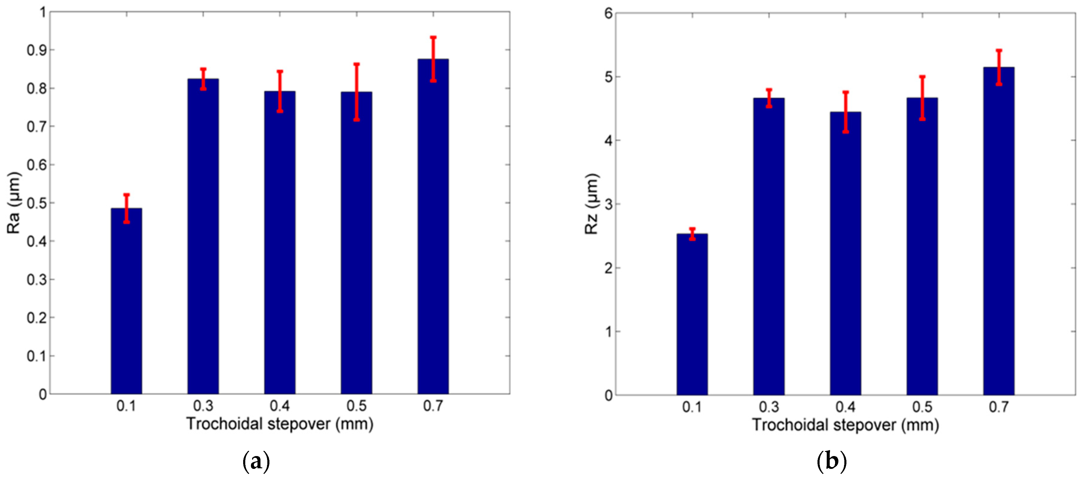
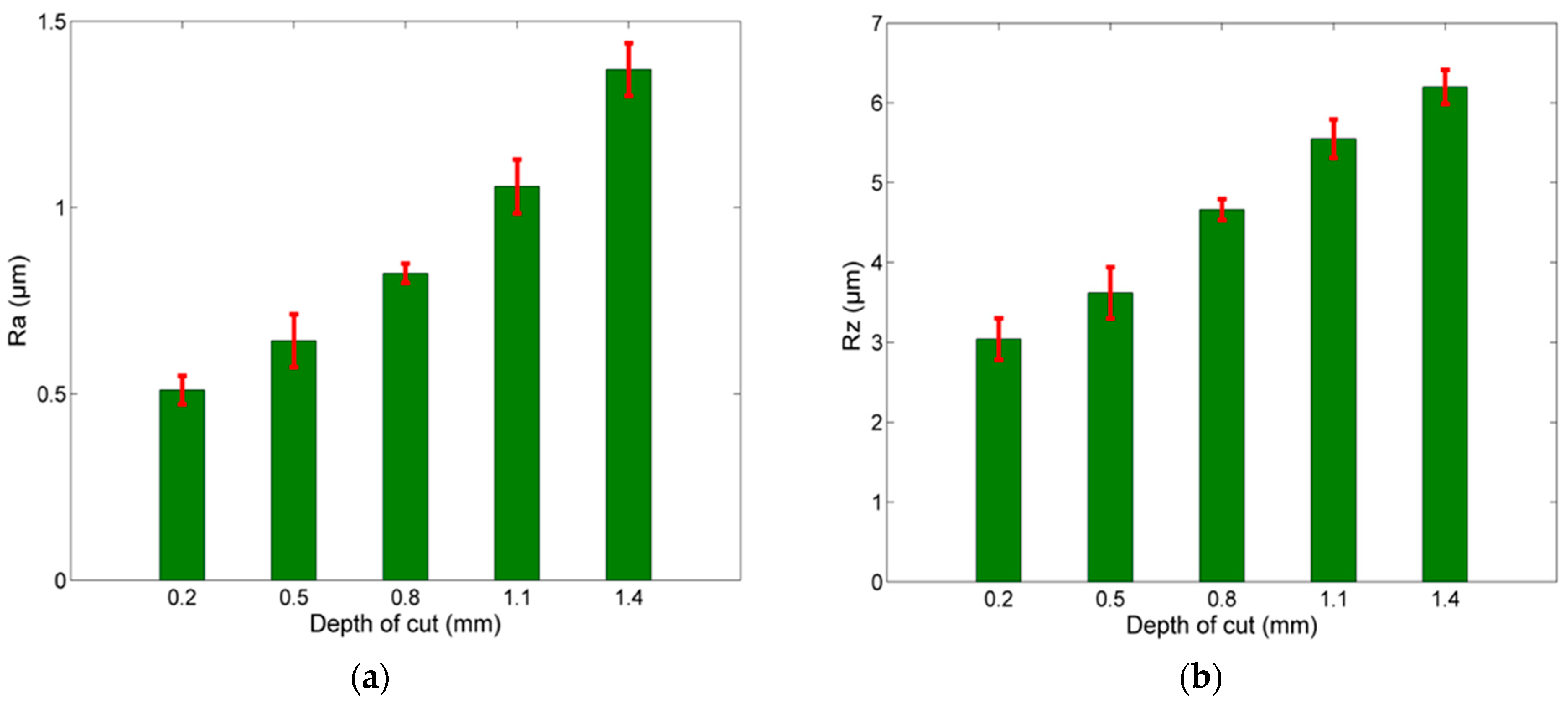
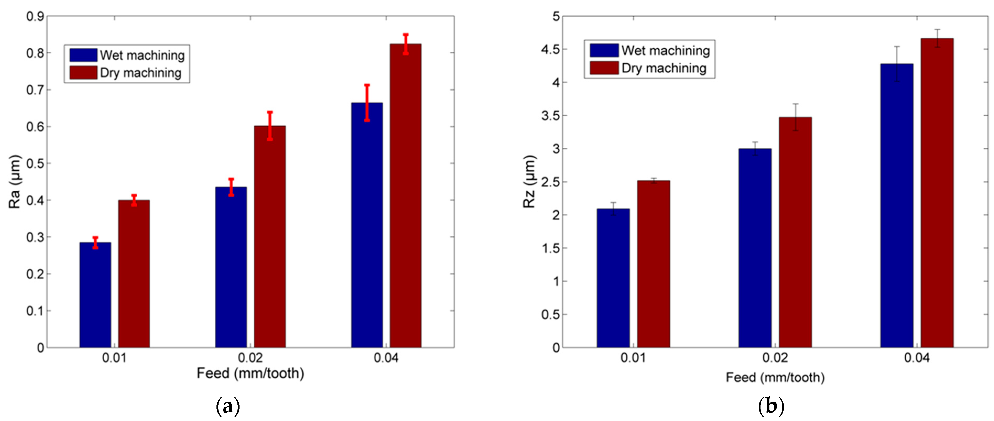
3.3. Effect of Depth of Cut, Coolant and Trochoidal Stepover on Surface Roughness

After the comparison between trochoidal and traditional slot milling was conducted based on the results from the two first series of experiments, the results regarding the three additional series of experiments are discussed. These results are presented in Table 4 and depicted in Figure 9, Figure 10 and Figure 11.
The first parameter investigated was pertinent to the trochoidal milling strategy itself, namely, trochoidal stepover. It was previously mentioned that a good practice for trochoidal milling is actually the use of stepover values below 10% of the cutting tool diameter, namely, 0.4 mm in the present work. In order to ascertain the effect of trochoidal stepover on surface roughness, experiments were carried out with trochoidal stepover values both over and below the limit value. From the results depicted in Figure 9a,b, it can be seen that the surface roughness increases considerably for low stepover values, it remains almost constant for stepover values near the limit value and increases again for stepover values relatively higher than the limit value.
The increase in the depth of cut was found to lead to a direct, almost linear increase in the surface roughness both for average and maximum values, as can be seen in Table 4 and Figure 10a,b. A sevenfold increase in the depth of cut led to an almost 2.7 times increase in surface roughness Ra. Similarly, Rz also increased as the depth of cut values became higher.
The use of coolant is widely known to favor the creation of smoother surfaces, as it can remove possible adherent chip fragments from the surface and generally leads to stabler cutting. In order to determine the extent to which the use of coolant affects the surface roughness in the cases of trochoidal milling, three experiments were carried out additionally under the same conditions with three previously conducted experiments. The results are presented in Table 4 and also depicted in Figure 11a,b. From these results, it becomes evident that the use of coolant has a direct effect on the surface quality, as it can reduce the surface roughness values considerably in respect to the same experiment conducted under dry machining conditions. The percentage reduction in Ra was between 19.35% and 28.80%, and the reduction in Rz between 8.25% and 16.92%, with the value 0.285 μm obtained in the 29th experiment being the overall lowest surface roughness value.

4. Conclusions

In the present work, an investigation regarding the surface quality obtained by the trochoidal milling strategy was performed in the case of the slot milling of aluminum alloy 6082. Two series of experiments were conducted in order to compare the performance of the trochoidal milling strategy with that of the traditional slot milling strategy regarding various surface roughness indicators, such as Ra, Rz, Rsk and Rku. Then, three additional series of experiments were conducted in order to investigate the effect of the depth of cut, coolant and trochoidal stepover on surface roughness during trochoidal milling. From the investigations, several useful conclusions were drawn.
The surface roughness pattern on the machined surface differs significantly between the two different milling strategies, as in the trochoidal milling strategy, the tool tip undergoes a complex path composed of two rotational motions and one translational one. Thus, in this case, the trochoidal curve pattern is altered by the superposition of additional marks.
The surface roughness indicators values can be more efficiently modeled by using power law models in respect to the two process parameters. It was shown that in both trochoidal and traditional milling, the Ra and Rz power law equations exhibited higher R2 values than the simple linear models.
The comparison of Ra and Rz values obtained by the two milling strategies revealed that in most cases, the trochoidal milling strategy can provide superior results both for Ra and Rz, especially for higher fz values. Thus, it is possible to use larger feed values while maintaining surface quality at acceptable levels.
Analysis of the skewness and kurtosis values revealed that there are some differences in the types of surface roughness profiles between the two milling strategies. More specifically, the trochoidal milling strategy leads to lower peaks and less sharp profiles, while the skewness and kurtosis values are less sensitive to variations in process parameters than in the case of traditional milling.
Finally, the investigation regarding the effect of the depth of cut, coolant and trochoidal stepover on surface roughness showed that an almost linear increase in Ra can be expected with an increase in the depth of cut, whereas the use of coolant can essentially reduce the surface roughness in all cases. The use of low trochoidal stepover values was proven to lead to better surface quality, whereas increasing its value over the appropriate limit leads eventually to a noticeable increase in Ra values.

Author Contributions

Conceptualization, N.E.K. and P.K.-O.; Data curation, N.E.K., P.K.-O. and S.K.; Formal analysis, N.E.K. and P.K.-O.; Funding acquisition, A.P.M.; Investigation, N.E.K., P.K.-O. and S.K.; Methodology, N.E.K.; Project administration, K.Z. and A.P.M.; Resources, S.K. and N.E.K.; Software, N.E.K. and S.K.; Supervision, K.Z. and A.P.M.; Validation, N.E.K., P.K.-O. and S.K.; Visualization, N.E.K. and S.K.; Writing—original draft, N.E.K. and P.K.-O.; Writing—review and editing, N.E.K., P.K.-O. and A.P.M. All authors have read and agreed to the published version of the manuscript.

Funding

This research received no external funding.

Informed Consent Statement

Not applicable.

Conflicts of Interest

The authors declare no conflict of interest.

References

  1. Li, Z.; Li, S.; Zhou, M. Study on Dynamic Simulation and Cutting Parameters Optimization on Complex Cutting Conditions Milling Process. In Proceedings of the 2010 International Conference on Intelligent Computation Technology and Automation, Changsha, China, 11–12 May 2010. [Google Scholar]
  2. Grechishnikov, V.A.; Petukhov, Y.E.; Pivkin, P.M.; Romanov, V.B.; Ryabov, E.A.; Yurasov, S.Y.; Yurasova, O.I. Trochoidal slot milling. Russ. Eng. Res. 2017, 37, 821–823. [Google Scholar] [CrossRef]
  3. Toh, C.K. Tool life and tool wear during high-speed rough milling using alternative cutter path strategies. Proc. Inst. Mech. Eng. B 2003, 217, 517–527. [Google Scholar] [CrossRef]
  4. Rodríguez-Barrero, S.; Fernández-Larrinoa, J.; Azkona, I.; López de Lacaille, L.N.; Polvorosa, R. Enhanced performance of nanostructured coatings for drilling by droplet elimination. Mat. Manuf. Process. 2014, 31, 593–602. [Google Scholar] [CrossRef]
  5. López de Lacalle, L.N.; Lamikiz, A.; Salgado, M.A.; Herranz, S.; Rivero, A. Process planning for reliable high-speed machining of moulds. Int. J. Prod. Res. 2002, 40, 2789–2809. [Google Scholar] [CrossRef]
  6. Suárez, A.; Veiga, F.; Polvorosa, R.; Artaza, T.; Holmberg, J.; López de Lacalle, L.N.; Wretland, A. Surface integrity and fatigue of non-conventional machined Alloy 718. J. Manuf. Process. 2019, 48, 44–50. [Google Scholar] [CrossRef]
  7. Otkur, M.; Lazoglu, I. Trochoidal milling. Int. J. Mach. Tool. Manuf. 2007, 47, 1324–1332. [Google Scholar] [CrossRef]
  8. Rauch, M.; Duc, E.; Hascoet, J.-Y. Improving trochoidal tool paths generation and implementation using process constraints modelling. Int. J. Mach. Tool. Manuf. 2008, 49, 375–383. [Google Scholar] [CrossRef]
  9. Ibaraki, S.; Yamaji, I.; Matsubara, A. On the removal of critical cutting regions by trochoidal grooving. Precis. Eng. 2010, 34, 467–473. [Google Scholar] [CrossRef] [Green Version]
  10. Ferreira, J.C.; Ochoa, D.M. A method for generating trochoidal tool paths for 2½D pocket milling process planning with multiple tools. Proc. Inst. Mech. Eng. B 2013, 227, 1287–1298. [Google Scholar] [CrossRef]
  11. Zhang, X.H.; Peng, F.Y.; Qiu, F.; Yan, R.; Li, B. Prediction of cutting force in trochoidal milling based on radial depth of cut. Adv. Mater. Res. 2014, 852, 457–462. [Google Scholar] [CrossRef]
  12. Shixiong, W.; Wei, M.; Bin, L.; Chengyong, W. Trochoidal machining for the high-speed milling of pockets. J. Mater. Process. Technol. 2016, 233, 29–43. [Google Scholar] [CrossRef]
  13. Pleta, A.; Ulutan, D.; Mears, L. An Investigation of Alternative Path Planning Strategies for Machining of Nickel-Based Superalloys. Procedia Manuf. 2015, 1, 556–566. [Google Scholar] [CrossRef] [Green Version]
  14. Pleta, A.; Niaki, F.A.; Mears, L. A comparative study on the cutting force coefficient identification between trochoidal and slot milling. Procedia Manuf. 2018, 26, 570–579. [Google Scholar] [CrossRef]
  15. Li, Z.; Xu, K.; Tang, K. A new trochoidal pattern for slotting operation. Int. J. Adv. Manuf. Technol. 2019, 102, 1153–1163. [Google Scholar] [CrossRef]
  16. Oh, N.-S.; Woo, W.-S.; Lee, C.-M. A study on the machining characteristics and energy efficiency of Ti-6Al-4V in laser-assisted trochoidal milling. Int. J. Precis. Eng. Manuf. 2018, 5, 37–45. [Google Scholar] [CrossRef]
  17. Zagórski, I.; Kulisz, M.; Kłonica, M.; Matuszak, J. Trochoidal Milling and Neural Networks Simulation of Magnesium Alloys. Materials 2019, 12, 2070. [Google Scholar] [CrossRef] [Green Version]
  18. Santhakumar, J.; Mohammed Iqbal, U. Parametric optimization of trochoidal step on surface roughness and dish angle in end milling of AISI D3 steel using precise measurements. Materials 2019, 12, 1335. [Google Scholar] [CrossRef] [Green Version]
  19. Volosova, M.A.; Fyodorov, S.V.; Opleshin, S.; Mosyanov, M. Wear resistance and titanium adhesion of cathodic arc deposited multi-component coatings for carbide end mills at the trochoidal milling of titanium alloy. Technologies 2020, 8, 38. [Google Scholar] [CrossRef]
  20. Šajgalík, M.; Kušnerová, M.; Harničárová, M.; Valíček, J.; Czán, A.; Czánova, T.; Drbúl, M.; Borzan, M.; Kmec, J. Analysis and prediction of the machining force depending on the parameters of trochoidal milling of hardened steel. Appl. Sci. 2020, 10, 1788. [Google Scholar] [CrossRef] [Green Version]
  21. Deng, Q.; Mo, R.; Chen, Z.C.; Chang, Z. An Analytical Approach to Cutter Edge Temperature Prediction in Milling and Its Application to Trochoidal Milling. Appl. Sci. 2020, 10, 1746. [Google Scholar] [CrossRef] [Green Version]
  22. Huang, X.; Wu, S.; Liang, L.; Li, X.; Huang, N. Efficient trochoidal milling based on medial axis transformation and inscribed ellipse. Int. J. Adv. Manuf. Technol. 2020, 111, 1069–1076. [Google Scholar] [CrossRef]
  23. Gross, D.; Friedl, F.; Meier, T.; Hanenkamp, N. Comparison of linear and trochoidal milling for wear and vibration reduced machining. Procedia CIRP 2020, 90, 563–567. [Google Scholar] [CrossRef]
  24. Svensson, L.-E.; Karlsson, L.; Larsson, H.; Karlsson, B.; Fazzini, M.J.; Karlsson, J. Microstructure and mechanical properties of friction stir welded aluminium alloys with special reference to AA 5083 and AA 6082. Sci. Technol. Weld. Join. 2020, 5, 285–296. [Google Scholar] [CrossRef]
  25. Liu, D.; Zhang, Y.; Luo, M.; Zhang, D. Investigation of Tool Wear and Chip Morphology in Dry Trochoidal Milling of Titanium Alloy Ti-6Al-4V. Materials 2019, 12, 1937. [Google Scholar] [CrossRef] [PubMed] [Green Version]
  26. Ducroux, E.; Prat, D.; Viprey, F.; Fromentin, G.; d’Acunto, A. Analysis and modeling of trochoidal milling in Inconel 718. Procedia CIRP 2019, 82, 473–478. [Google Scholar] [CrossRef]
  27. Pleta, A.; Niaki, F.A.; Mears, L. Investigation of chip thickness and force modeling of trochoidal milling. Procedia Manuf. 2017, 10, 612–621. [Google Scholar] [CrossRef]
  28. Pleta, A.; Nithyanand, G.; Niaki, F.A.; Mears, L. Identification of optimal machining parameters in trochoidal milling of Inconel 718 for minimal force and tool wear and investigation of corresponding effects on machining affected zone depth. J. Manuf. Process. 2019, 43, 54–62. [Google Scholar] [CrossRef]
  29. Sedlaček, M.; Silva Vilhena, L.M.; Podgornik, B.; Vižintin, J. Surface topography modeling for reduced friction. Strojniškivestnik 2011, 57, 674–680. [Google Scholar]
  30. Tseng, T.-L.; Konada, U.; Kwon, Y. A novel approach to predict surface roughness in machining operations using fuzzy set theory. J. Comput. Des. Eng. 2016, 3, 1–13. [Google Scholar] [CrossRef] [Green Version]
  31. Zagórski, I.; Koprysa, J. Surface quality in milling of AZ91D magnesium alloy. Adv. Sci. Technol. Res. J. 2019, 13, 119–129. [Google Scholar] [CrossRef]
  32. Tufescu, A.; Cretu, S. Simulation of the non-gaussian roughness with specified values for the high order moments. J. Balk. Tribol. Assoc. 2003, 19, 391–400. [Google Scholar]
Figure 1. (a) The machine tool used for the experiments; (b) the cutting tool and workpiece used for the experiments.
Machines 09 00075 g001
Figure 2. Images of the two different solid carbide end mills used for the experiments.
Machines 09 00075 g002
Figure 3. Images from the machined surfaces of experiments: (a) no.4 (trochoidal milling), (b) no.8 (trochoidal milling), (c) no.14 (traditional milling) and (d) no. 18 (traditional milling).
Machines 09 00075 g003
Figure 4. Comparison of experimental and predicted results for the cases of trochoidal milling regarding: (a) Ra and (b) Rz.
Machines 09 00075 g004
Figure 5. Comparison of experimental and predicted results for the cases of traditional milling regarding: (a) Ra and (b) Rz.
Machines 09 00075 g005
Figure 6. (a) Ra and (b) Rz results under different process conditions during trochoidal machining.
Machines 09 00075 g006
Figure 7. (a) Ra and (b) Rz results under different process conditions during traditional milling.
Machines 09 00075 g007
Figure 8. Rsk–Rku pairs for each experiment.
Machines 09 00075 g008
Figure 9. Surface roughness variation in respect to trochoidal stepover: (a) Ra and (b) Rz.
Machines 09 00075 g009
Figure 10. Surface roughness variation in respect to depth of cut: (a) Ra and (b) Rz.
Machines 09 00075 g010
Figure 11. Surface roughness variation in cases with and without coolant: (a) Ra and (b) Rz.
Machines 09 00075 g011
Table 1. Process parameters values.
ParameterValues
depth of cut (ap)0.2, 0.5, 0.8, 1.1, 1.4 mm
slot width (w)6 mm
cutting tool diameter (d)6 mm (traditional milling)
4 mm (trochoidal milling)
cutting speed (vc)80 m/min, 200 m/min
feed (fz)0.01, 0.02, 0.04, 0.06, 0.08 mm/tooth
trochoidal step (Ptroch)0.1, 0.3, 0.4, 0.5, 0.7 mm
cutting length (L)60 mm
Table 2. Chemical composition of the aluminum workpiece material.
Al (%)Si (%)Fe (%)Cu (%)Mn (%)Mg (%)Cr (%)Zn (%)Ti (%)
Bal. 0.7–1.30.45–0.550.08–0.120.4–1.00.6–1.20.23–0.270.18–0.220.08–0.12
Table 3. Experimental surface roughness measurements.
NoMilling Strategyvc (m/min)fz (mm/tooth)Ra (μm)Rz (μm)
1Trochoidal800.010.4122.508
2Trochoidal800.020.6563.673
3Trochoidal800.041.0485.443
4Trochoidal800.061.3047.589
5Trochoidal800.081.6527.732
6Trochoidal2000.010.42.517
7Trochoidal2000.020.6023.472
8Trochoidal2000.040.8244.662
9Trochoidal2000.060.7884.159
10Trochoidal2000.080.8364.701
11Traditional800.010.3772.757
12Traditional800.020.6874.313
13Traditional800.041.4626.975
14Traditional800.061.9147.625
15Traditional800.082.0218.194
16Traditional2000.010.2973.624
17Traditional2000.020.6614.864
18Traditional2000.041.2555.96
19Traditional2000.061.3036.457
20Traditional2000.081.528.124
Table 4. Surface roughness measurements for the last three series of experiments.
NoTrochoidal Stepover (mm)CoolantDepth of Cut (mm)vc (m/min)fz (mm/tooth)Ra (μm)Rz (μm)
210.1No0.82000.040.4852.531
220.4No0.82000.040.7924.444
230.5No0.82000.040.794.666
240.7No0.82000.040.8765.146
250.3No0.22000.040.5113.04
260.3No0.52000.040.6433.62
270.3No1.12000.041.0575.55
280.3No1.42000.041.376.199
290.3Yes0.82000.010.2852.091
300.3Yes0.82000.020.4352.998
310.3Yes0.82000.040.6654.277
Publisher’s Note: MDPI stays neutral with regard to jurisdictional claims in published maps and institutional affiliations.

