
Development of a New Finishing Process Combining a Fixed Abrasive Polishing with Magnetic Abrasive Finishing Process

Abstract
:1. Introduction
2. Processing Principle and Experimental Setup
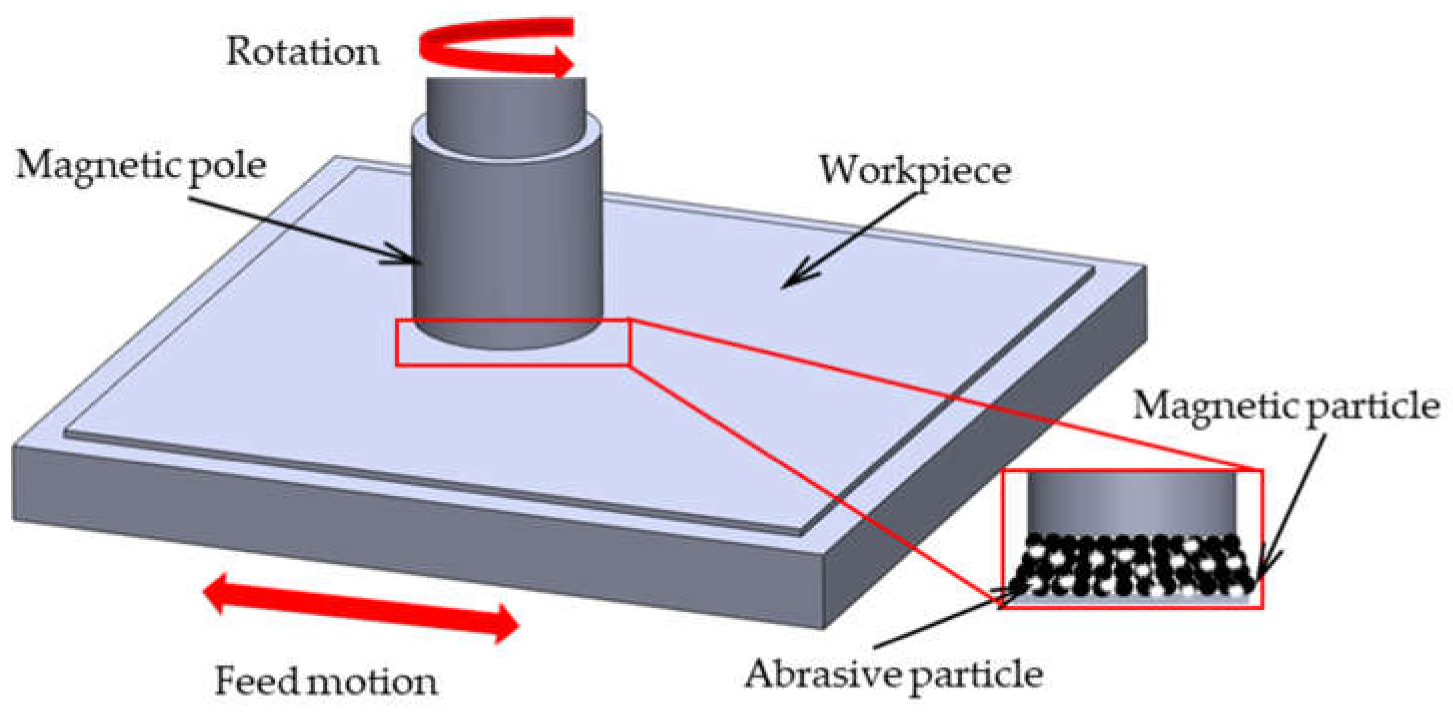
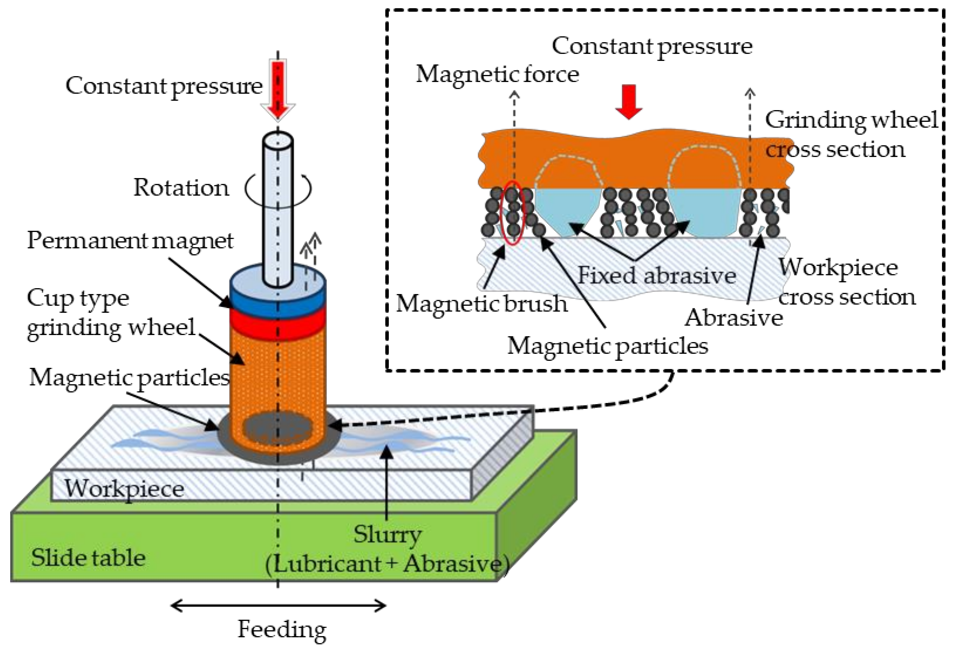
2.1. Processing Principle
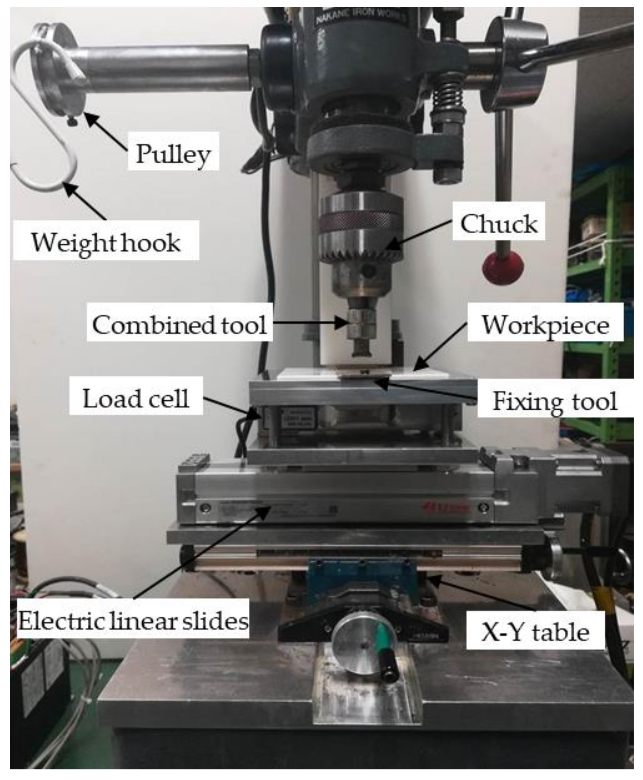
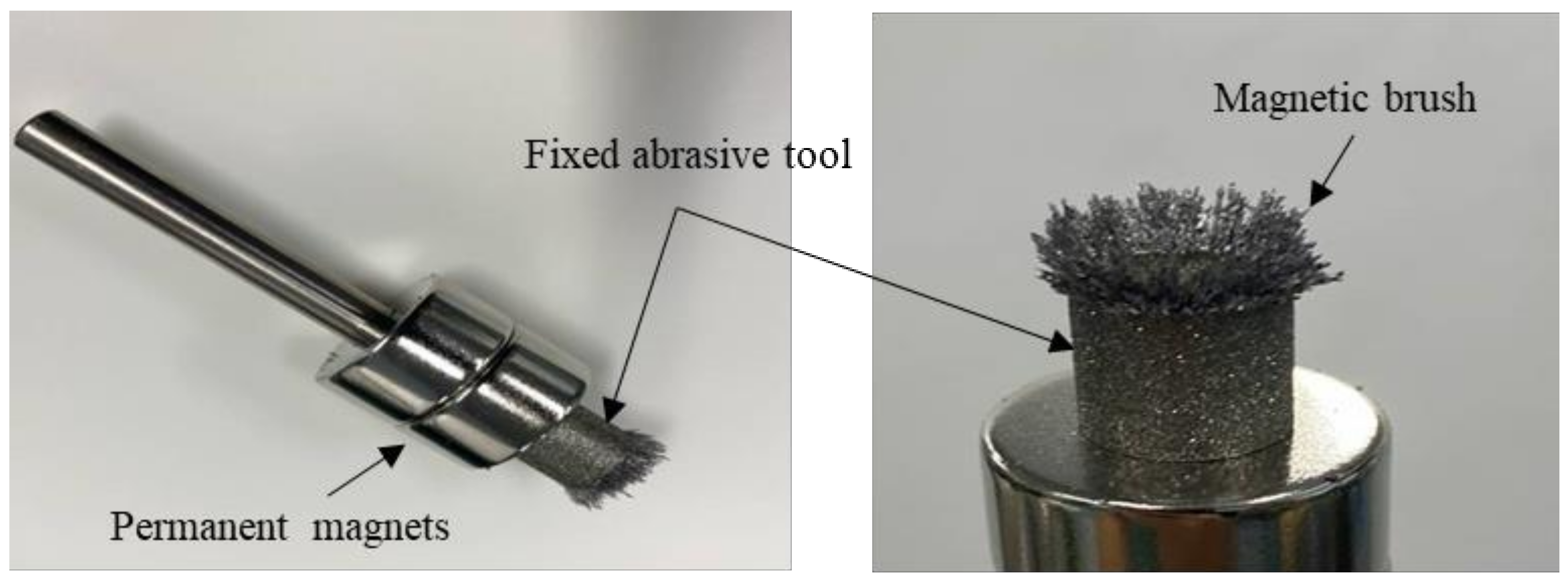
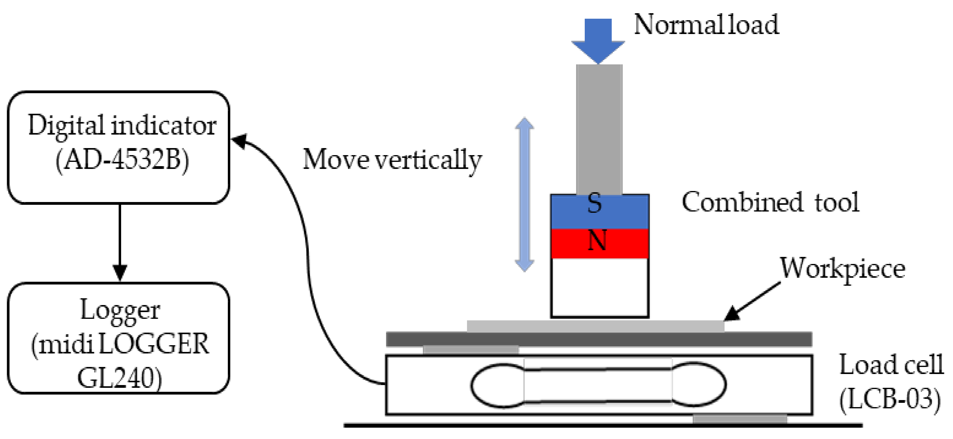
2.2. Experimental Setup
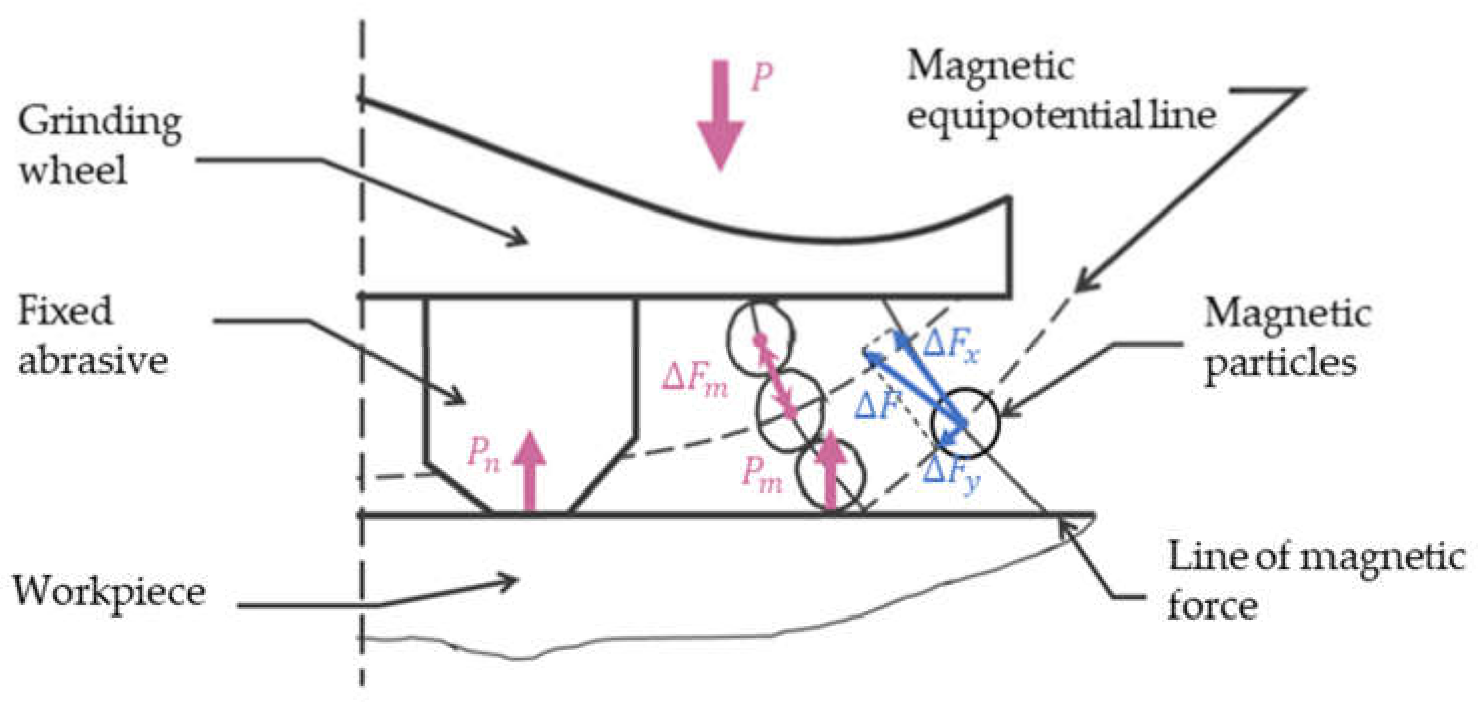
2.3. Force Analysis
3. Experimental Conditions and Method
4. Experimental Results and Discussion
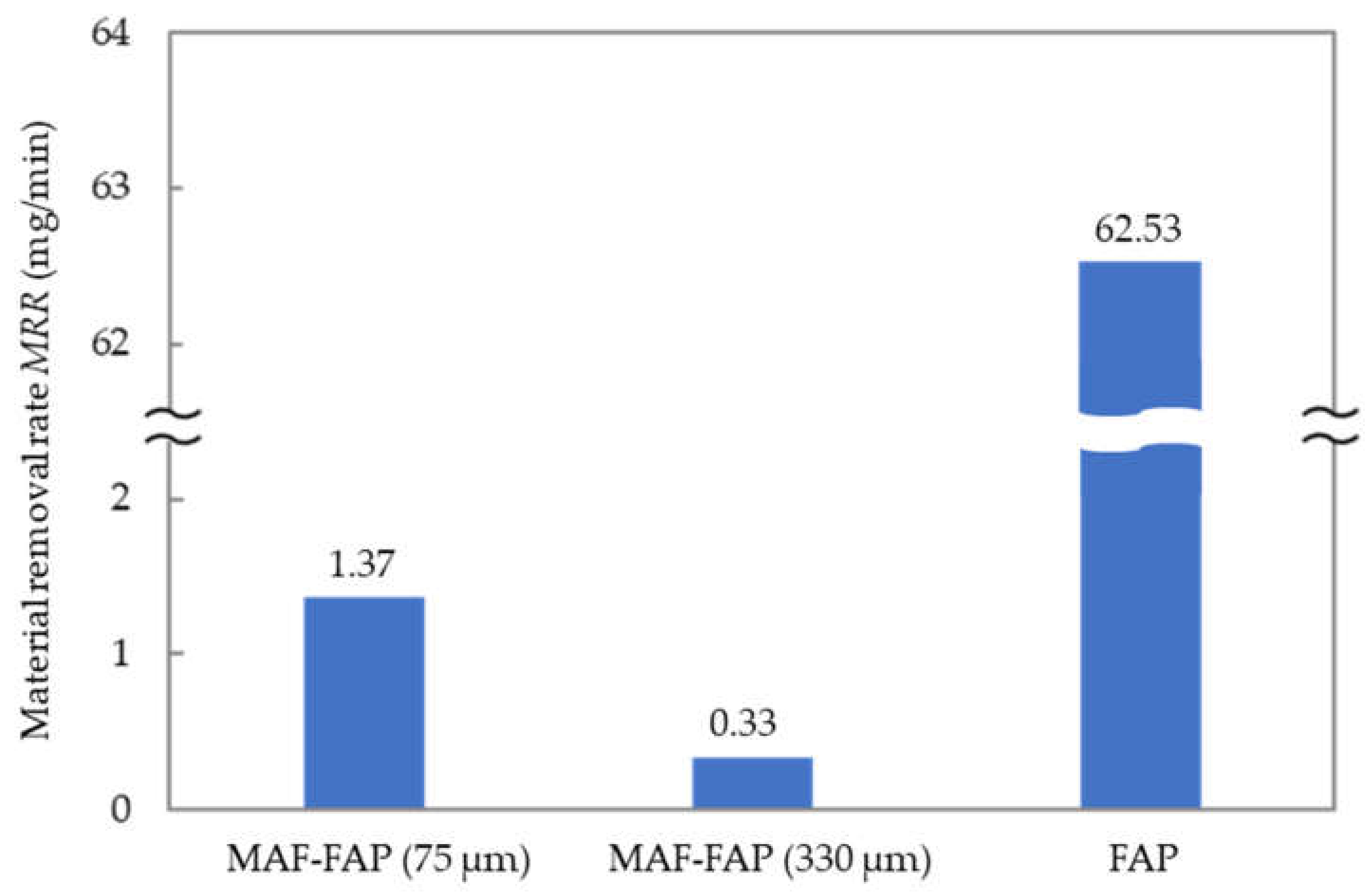
4.1. Comparison of FAP and MAF-FAP
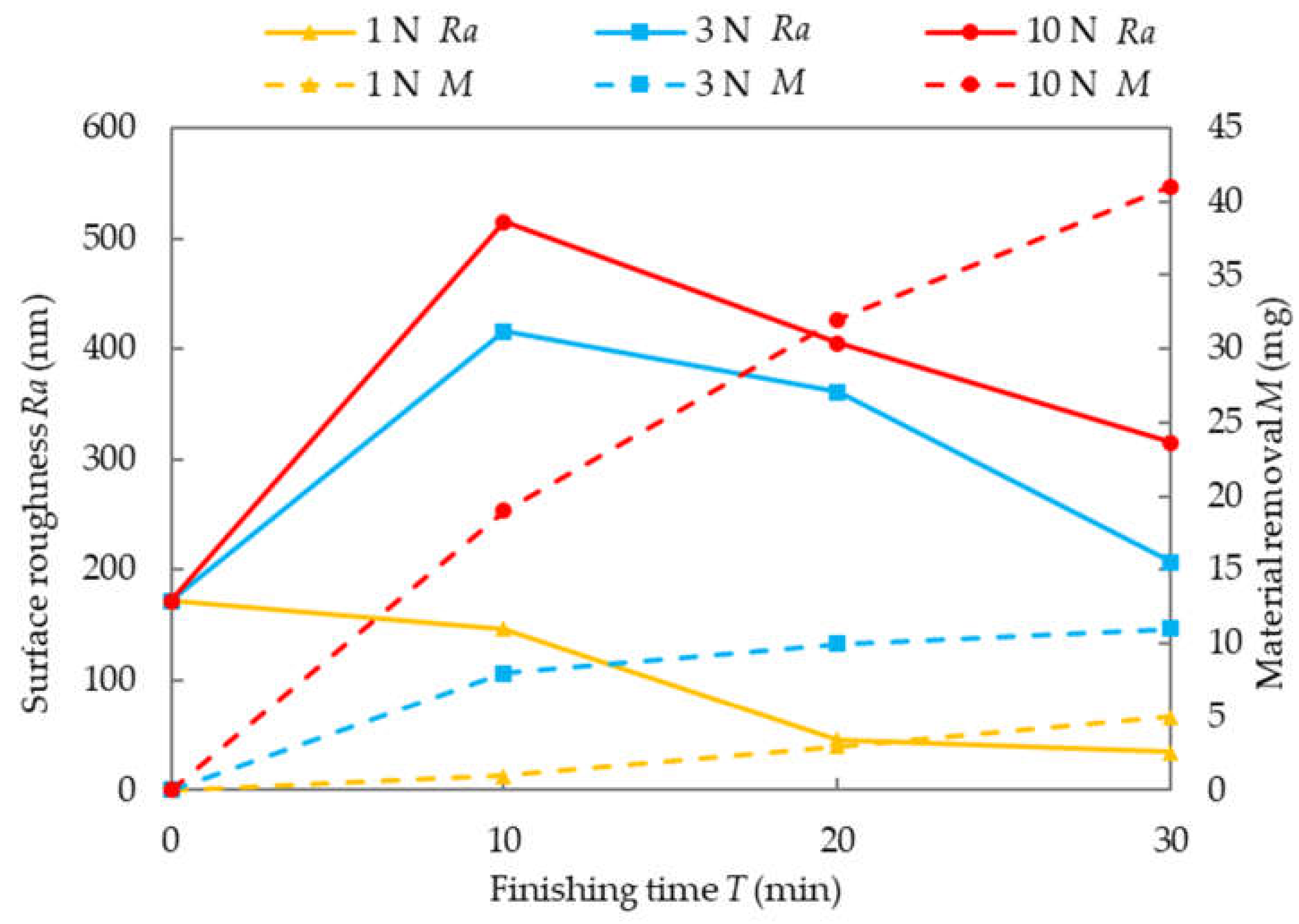
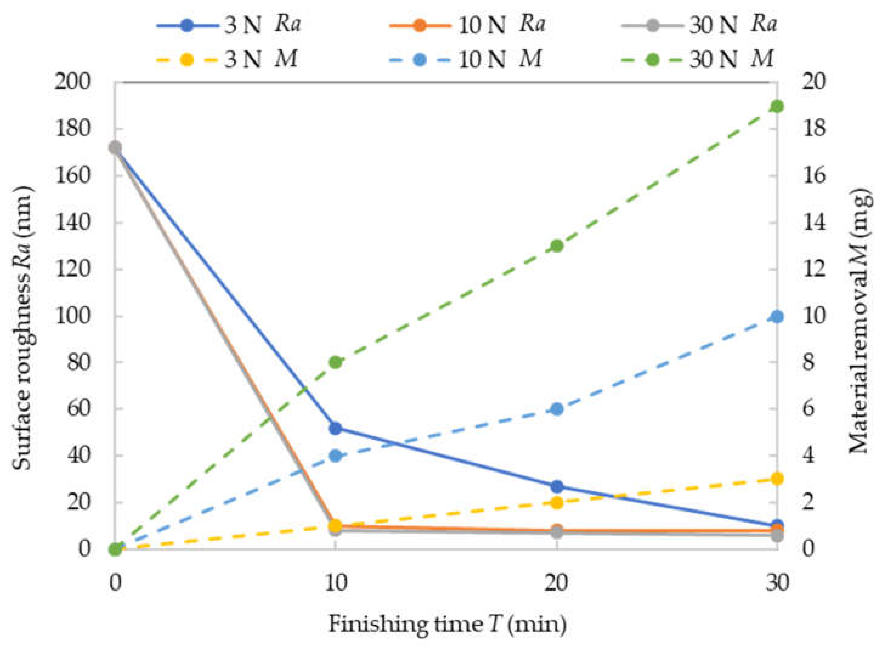
4.2. Normal Load
5. Conclusions
- A new finishing process is proposed, which combines the magnetic abrasive finishing process and the fixed abrasive polishing process.
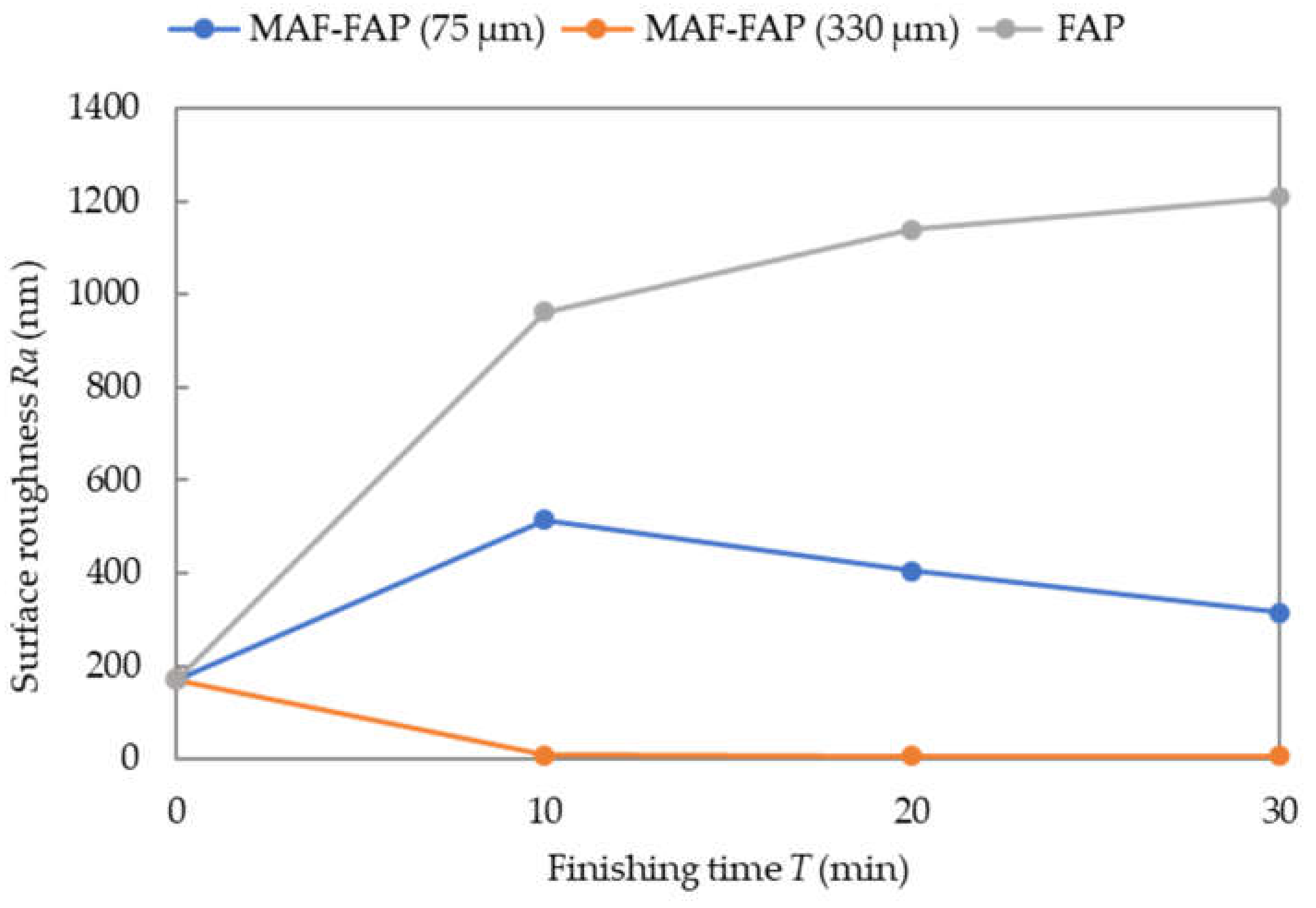
- Under the experimental conditions, when the average diameter of the magnetic particles is 330 μm and the normal load is 30 N, the best surface quality and the highest finishing efficiency can be obtained.
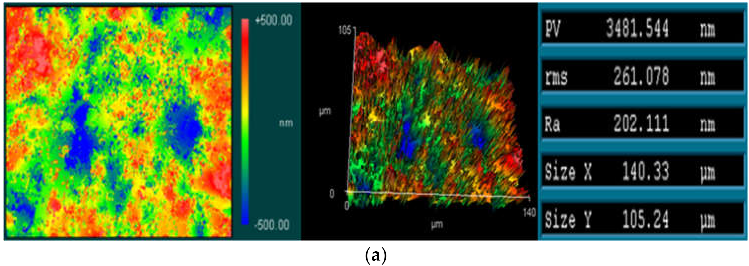
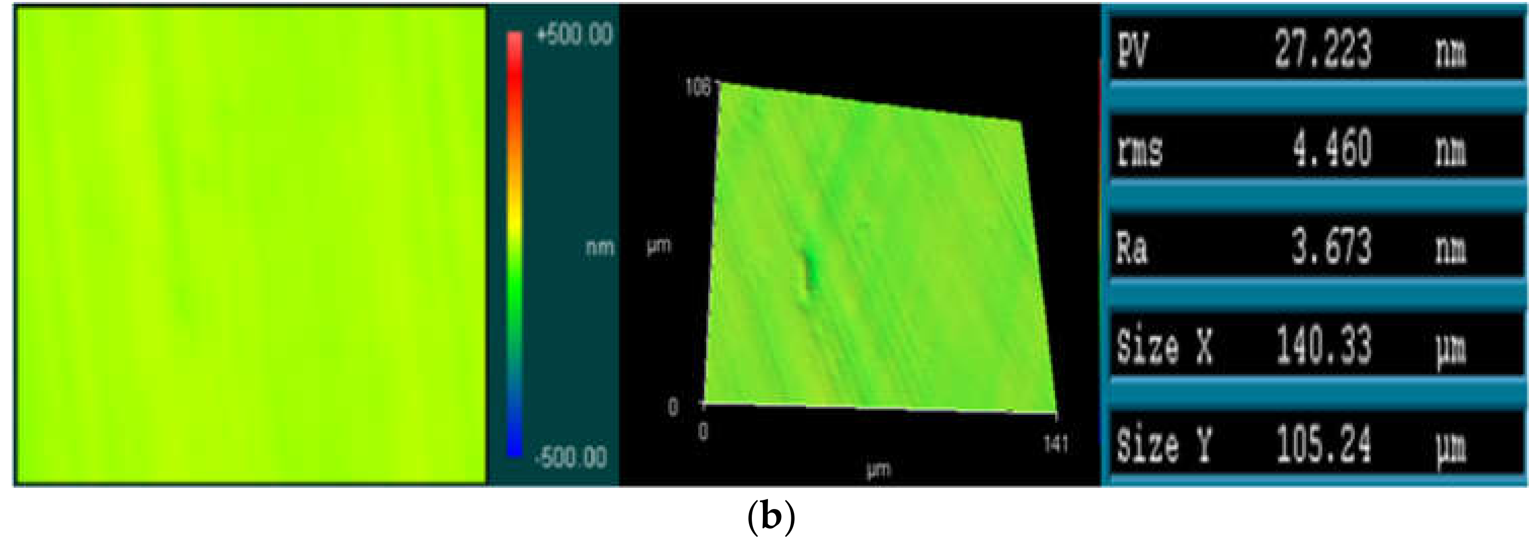
- According to the experimental results, the surface roughness of the alumina ceramic plate was improved from 202.11 nm Ra to 3.67 nm Ra within 30 min.
Author Contributions
Funding
Institutional Review Board Statement
Informed Consent Statement
Data Availability Statement
Conflicts of Interest
References
- Zou, Y.; Shinmura, T. Development of a new magnetic field assisted deburring technology for inside surface using permanent magnets and magnetic particles: Machining principle and a few deburring characteristics. J. Jpn. Soc. Abras. Technol. 2007, 51, 94–99. (In Japanese) [Google Scholar]
- Yamaguchi, H.; Shinmura, T.; Kobayashi, A. Development of an internal magnetic abrasive finishing process for nonmagnetic complex shaped tubes. JSME Int. J. Ser. C 2001, 44, 275–281. [Google Scholar] [CrossRef] [Green Version]
- Kala, P.; Pandey, P.M.; Verma, G.C.; Sharma, V. Understanding flexible abrasive brush behavior for double disk magnetic abrasive finishing based on force signature. J. Manuf. Process. 2017, 28, 442–448. [Google Scholar] [CrossRef]
- Shinmura, T.; Aizawa, T. Study on magnetic abrasive finishing process-development of plane finishing apparatus using a stationary type electromagnet. Bull. Jpn. Soc. Precis. Eng. 1989, 23, 236–239. [Google Scholar]
- Shinmura, T.; Aizawa, T. Development of plane magnetic abrasive finishing apparatus and its finishing performance. (2nd report). Finishing apparatus using a stationary type electromagnet. J. Jpn. Soc. Precis. Eng. 1988, 54, 928–933. [Google Scholar] [CrossRef] [Green Version]
- Shinmura, T.; Takazawa, K.; Hatano, E.; Matsunaga, M.; Matsuo, T. Study on Magnetic Abrasive Finishing. CIRP Ann. 1990, 39, 325–328. [Google Scholar] [CrossRef]
- Shinmura, T. Development of Magnetic Abrasive Finishing Apparatus using Vibratory Magnetic Poles and Its Finishing Performance. JSPE 1988, 54, 2170. [Google Scholar]
- Wu, J.; Zou, Y.; Sugiyama, H. Study on ultra-precision magnetic abrasive finishing process using low frequency alternating magnetic field. J. Magn. Magn. Mater. 2015, 386, 50–59. [Google Scholar] [CrossRef]
- Zou, Y.; Xie, H.; Dong, C.; Wu, J. Study on complex micro surface finishing of alumina ceramic by the magnetic abrasive finishing process using alternating magnetic field. Int. J. Adv. Manuf. Technol. 2018, 97, 2193–2202. [Google Scholar] [CrossRef]
- Xie, H.; Zou, Y.; Dong, C.; Wu, J. Study on the magnetic abrasive finishing process using alternating magnetic field: Investigation of mechanism and applied to aluminum alloy plate. Int. J. Adv. Manuf. Technol. 2019, 102, 1509–1520. [Google Scholar] [CrossRef]
- Wang, Y.; Hu, D. Study on the inner surface finishing of tubing by magnetic abrasive finishing. Int. J. Mach. Tools Manuf. 2005, 45, 43–49. [Google Scholar] [CrossRef]
- Jiao, A.; Zhang, G.; Liu, B.; Liu, W. Study on improving hole quality of 7075 aluminum alloy based on magnetic abrasive finishing. Adv. Mech. Eng. 2020, 12. [Google Scholar] [CrossRef]
- Vahdati, M.; Vahdati, N. Micromachining of aluminum pipes using magnetic abrasive finishing. J. Vac. Sci. Technol. B Microelectron. Nanometer Struct. Process. Meas. Phenom. 2009, 27, 1503–1505. [Google Scholar] [CrossRef]
- Gheisari, R.; Ghasemi, A.A.; Jafarkarimi, M.; Mohtaram, S. Experimental studies on the ultra-precision finishing of cylindrical surfaces using magnetorheological finishing process. Prod. Manuf. Res. 2014, 2, 550–557. [Google Scholar] [CrossRef] [Green Version]
- Yin, S.; Shinmura, T. Vertical vibration-assisted magnetic abrasive finishing and deburring for magnesium alloy. Int. J. Mach. Tools Manuf. 2004, 44, 1297–1303. [Google Scholar] [CrossRef]
- Yin, S.; Shinmura, T. A comparative study: Polishing characteristics and its mechanisms of three vibration modes in vibration-assisted magnetic abrasive polishing. Int. J. Mach. Tools Manuf. 2004, 44, 383–390. [Google Scholar] [CrossRef]
- Lin, C.; Yang, L.; Chow, H. Study of magnetic abrasive finishing in free-form surface operations using the Taguchi method. Int. J. Adv. Manuf. Technol. 2007, 34, 122–130. [Google Scholar] [CrossRef]
- Guo, J.; Jong, H.J.H.; Kang, R.; Guo, D. Novel localized vibration-assisted magnetic abrasive polishing method using loose abrasives for V-groove and Fresnel optics finishing. Opt. Express 2018, 26, 11608–11619. [Google Scholar] [CrossRef]
- Chen, J.; Zhu, Y.; Wang, J.; Peng, Y.; Yao, J.; Ming, S. Relationship between mechanical properties and processing performance of agglomerated diamond abrasive compared with single diamond abrasive. Diam. Relat. Mater. 2019, 100, 107595. [Google Scholar] [CrossRef]
- Nguyen, N.Y.; Zhong, Z.W.; Tian, Y.B. Analysis and improvement of the pad wear profile in fixed abrasive polishing. Int. J. Adv. Manuf. Technol. 2016, 85, 1159–1165. [Google Scholar] [CrossRef]
- Peng, W.; Yao, C.Y.; Lv, X.; Liu, F.Q.; Gao, T.; Yuan, J.L. Experimental Study on New Bonding Materials for Developing Nano-Grinding Plates. Key Eng. Mater. 2007, 329, 489–494. [Google Scholar] [CrossRef]
- Sato, R. Basic Properties of Fixed Abrasive Polishing by Alumina Abrasive Grain for Si Wafer—Effects of Actual Contact Area and Grain Size-. Int. J. Autom. Comput. 2014, 8, 592–597. [Google Scholar] [CrossRef]
- Tian, Y.B.; Zhong, Z.W.; Lai, S.T.; Ang, Y.J. Development of fixed abrasive chemical mechanical polishing process for glass disk substrates. J. Adv. Manuf. Technol. 2013, 68, 993–1000. [Google Scholar] [CrossRef]
- Hu, Z.; Fang, C.; Deng, W.; Zhao, Z.; Lin, Y.; Xu, X. Speed ratio optimization for ceramic lapping with fixed diamond pellets. J. Adv. Manuf. Technol. 2017, 90, 3159–3169. [Google Scholar] [CrossRef]
- Luo, Q.; Lu, J.; Xu, X. Study on the processing characteristics of SiC and sapphire substrates polished by semi-fixed and fixed abrasive tools. Tribol. Trans. 2016, 104, 191–203. [Google Scholar] [CrossRef]
- Luo, Q.; Lu, J.; Xu, X. A comparative study on the material removal mechanisms of 6H-SiC polished by semi-fixed and fixed diamond abrasive tools. Wear 2016, 350, 99–106. [Google Scholar] [CrossRef]
- Huang, S.; Li, X.; Yu, B.; Jiang, Z.; Huang, H. Machining characteristics and mechanism of GO/SiO2 nanoslurries in fixed abrasive lapping. J. Mater. Process. Technol. 2020, 277, 116444. [Google Scholar] [CrossRef]
- Zhou, P.; Zhu, N.; Xu, C.; Niu, F.; Li, J.; Zhu, Y. Mechanical removal of SiC by multi-abrasive particles in fixed abrasive polishing using molecular dynamics simulation. Comput. Mater. Sci. 2021, 191, 110311. [Google Scholar] [CrossRef]
- Cho, B.J.; Kim, H.M.; Manivannan, R.; Moon, D.J.; Park, J.G. On the mechanism of material removal by fixed abrasive lapping of various glass substrates. Wear 2013, 302, 1334–1339. [Google Scholar] [CrossRef]
- Jiao, F.; Zhao, B. Research on Ultrasonic-Assisted Fixed-Abrasive Lapping Technology for Engineering Ceramics Cylindrical Part. J. Micro Nanomanuf. 2017, 5, 021001. [Google Scholar] [CrossRef]
- Shinmura, T.; Takazawa, K.; Hatano, E. Study on magnetic abrasive finishing. Bull. Japan Soc. Precis. Eng. 1987, 21, 139–141. [Google Scholar] [CrossRef]
- Chang, G.; Yan, B.; Hsu, R.T. Study on cylindrical magnetic abrasive finishing using unbonded magnetic abrasives. Int. J. Mach. Tools Manuf. 2002, 42, 575–583. [Google Scholar] [CrossRef]
- Singh, A.K.; Jha, S.; Pandey, P.M. Design and development of nanofinishing process for 3D surfaces using ball end MR finishing tool. Int. J. Mach. Tools Manuf. 2011, 51, 142–151. [Google Scholar] [CrossRef]
- Kansal, H.; Singh, A.K.; Grover, V. Magnetorheological nano-finishing of diamagnetic material using permanent magnets tool. Precis. Eng. 2018, 51, 30–39. [Google Scholar] [CrossRef]
- Yamaguchi, H.; Srivastava, A.K.; Tan, M.A.; Riveros, R.E.; Hashimoto, F. Magnetic abrasive finishing of cutting tools for machining of titanium alloys. CIRP Ann. 2012, 61, 311–314. [Google Scholar] [CrossRef]
- Natsume, M.; Shinmura, T. Study on the mechanism of plane magnetic abrasive finishing process—Elucidation of normal force characteristics. Trans. Jpn. Soc. Mech. Eng. 2008, 74, 212–218. (In Japanese) [Google Scholar] [CrossRef] [Green Version]
- Shinmura, T.; Hatano, E.; Takazawa, K. Development of spindle-finish type finishing apparatus and its finishing performance using a magnetic abrasive machining process. Bull. Jpn. Soc. Precis. Eng. 1986, 20, 79–84. (In Japanese) [Google Scholar]


| Parameters | Conditions |
|---|---|
| Workpiece | Alumina ceramic plate (SSA-S) (100 × 100 × 2.5 mm3) |
| Fixed abrasive tool | Cup-type electrodeposition diamond wheel # 120 (KURE GRINDING WHEEL SDEM21) Grinding surface: Outer diameter 10 mm × Inner diameter 8 mm) |
| Grinding fluid | Water insoluble polishing oil (Castrol Honailo 988): 3 mL |
| Abrasive | Diamond abrasive (2–4 μm) (TOMEI CARAT: 50): 0.15 g |
| Permanent magnet | Nd–Fe–B ring permanent magnet × 2 (Outer diameter 19 mm × Inner diameter 6.5 mm× 10 mm) |
| Magnetic particles | Electrolytic iron powder, 75 μm in mean dia: 0.15 g Electrolytic iron powder, 330 μm in mean dia: 0.15 g |
| Rotational speed | 560 rpm |
| Feeding speed | 2 mm/s |
| Load | 1 N, 3 N, 10 N, 30 N |
| Finishing time | 10 min × 3 |
| Surface roughness before finishing | Ra: 0.171 μm (0.140–0.210 μm) |
| Parameters | Conditions |
|---|---|
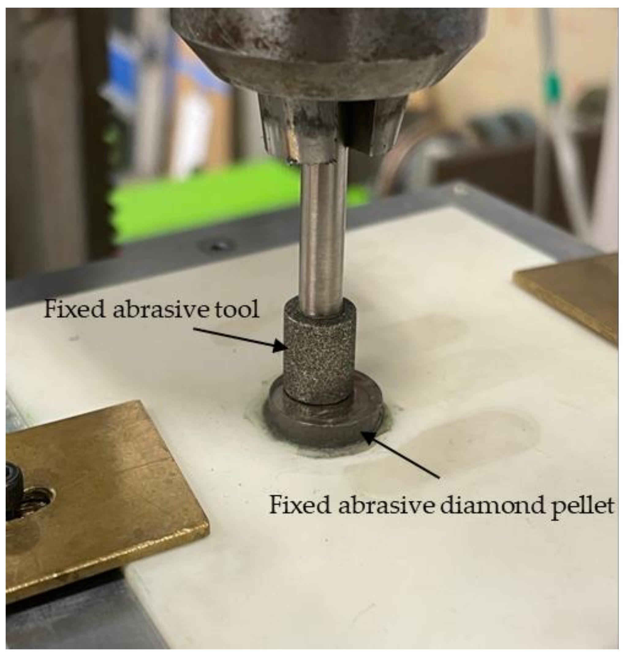
| Pretreatment tool | Fixed abrasive diamond pellet |
| Grinding fluid | Water insoluble polishing oil (Castrol Honailo 988): 3 mL |
| Rotational speed | 1800 rpm |
| Feeding speed | 0.01 mm/s |
| Load | 4 N |
| Finishing time | 10 min |
Publisher’s Note: MDPI stays neutral with regard to jurisdictional claims in published maps and institutional affiliations. |
© 2021 by the authors. Licensee MDPI, Basel, Switzerland. This article is an open access article distributed under the terms and conditions of the Creative Commons Attribution (CC BY) license (https://creativecommons.org/licenses/by/4.0/).
Share and Cite
Zou, Y.; Satou, R.; Yamazaki, O.; Xie, H. Development of a New Finishing Process Combining a Fixed Abrasive Polishing with Magnetic Abrasive Finishing Process. Machines 2021, 9, 81. https://doi.org/10.3390/machines9040081
Zou Y, Satou R, Yamazaki O, Xie H. Development of a New Finishing Process Combining a Fixed Abrasive Polishing with Magnetic Abrasive Finishing Process. Machines. 2021; 9(4):81. https://doi.org/10.3390/machines9040081
Chicago/Turabian StyleZou, Yanhua, Ryunosuke Satou, Ozora Yamazaki, and Huijun Xie. 2021. "Development of a New Finishing Process Combining a Fixed Abrasive Polishing with Magnetic Abrasive Finishing Process" Machines 9, no. 4: 81. https://doi.org/10.3390/machines9040081