Article

Infrared Laser Speckle Projection-Based Multi-Sensor Collaborative Human Body Automatic Scanning System

1
School of Mechanical Engineering, Shanghai Jiao Tong University, Shanghai 200240, China
2
State Key Laboratory of Mechanical System and Vibration, Shanghai 200240, China
3
Software Center, Shanghai H VISIONS Technology, Shanghai 200241, China
*
Author to whom correspondence should be addressed.
Machines 2021, 9(11), 299; https://doi.org/10.3390/machines9110299
Submission received: 25 October 2021 / Revised: 17 November 2021 / Accepted: 21 November 2021 / Published: 22 November 2021
(This article belongs to the Special Issue Industrial Informatics and Digital Twin)

Abstract

:
Human body scanning is an important means to build a digital 3D model of the human body, which is the basis for intelligent clothing production, human obesity analysis, and medical plastic surgery applications, etc. Comparing to commonly used optical scanning technologies such as laser scanning and fringe structured light, infrared laser speckle projection-based 3D scanning technology has the advantages of single-shot, simple control, and avoiding light stimulation to human eyes. In this paper, a multi-sensor collaborative digital human body scanning system based on near-infrared laser speckle projection is proposed, which occupies less than 2 m2 and has a scanning period of about 60 s. Additionally, the system calibration method and control scheme are proposed for the scanning system, and the serial-parallel computing strategy is developed based on the unified computing equipment architecture (CUDA), so as to realize the rapid calculation and automatic registration of local point cloud data. Finally, the effectiveness and time efficiency of the system are evaluated through anthropometric experiments.

1. Introduction

Human body scanning is an important means to build a digital three-dimensional model of the human body. Intelligent clothing production [1], medical plastic surgery [2], 3D printing and other fields have wide demands for non-contact human body scanning based on optical measurement technology [3,4,5,6]. Under the background of intelligent manufacturing, the industrialized tailoring of clothing is booming gradually and transforming to the goal of intelligence and individuation constantly. The clothing production mode is to design and make clothing according to the clothing style selected by users and their body size, which not only meets the requirements of users’ physical characteristics, but also meets their personalized needs. At present, in addition to the daily clothing sewed according to the uniform body standard, some clothing needs to be tailored, such as suits, military uniforms, service uniforms and so on. The traditional custom-made mode mainly relies on experienced masters to measure the parameters needed for garment making, such as shoulder width, waist circumference, and arm length, and then cut and sew according to the measured parameters. Take the customization of a high-class suit as an example, which goes through complicated and lengthy processes such as size measurement, white embryo making, white embryo fitting, fabric confirmation, and garment sewing [7]. In addition, the fit and comfort of clothes depends largely on the tailor’s personal experience. In order to solve the above problems, digital intelligent clothing customization technology based on garment parameter extraction [8] and white embryo production from the digital 3D model of the user comes into being. Therefore, the complete 3D human body scanning is the foundation of intelligent garment manufacturing. The point cloud of the human body can be obtained by 3D scanning, which can quickly and accurately obtain the parameters of several key parts of the garment. At the same time, it can also personalize the parts with special needs, such as abdomen and back, which can greatly improve the comfort and fit of clothing to customers.
Commonly used optical 3D scanning techniques mainly include laser triangulation [9,10] and structured light [11,12]. Laser triangulation is a point/line measurement method, which has the advantages of high measurement accuracy and strong robustness, but the efficiency is too low for human body scanning. Structured light measurement is a high-precision area array measurement technology; stripe structured light generally needs to project multiple coded patterns to obtain complete high-resolution data, during the process the object needs to keep still. Speckle structured light is based on the principle of binocular stereo vision, which projects speckle patterns with high randomness and high contrast on the surface of the object, and then realizes accurate stereo matching by digital speckle correlation [13,14]. Therefore, the speckle projection-based 3D scanning technology is a single-shot 3D measurement technology with high precision. With the continuous application of intelligent garment technology, single speckle projection measurement technology has obvious advantages in human body scanning because of its advantages of dynamic measurement, high precision and full-field measurement.
Due to a limited field of view from a single perspective, it is necessary to register the data from multiple views of angle to collect complete human body data. The multi-view 3D points registration method can be divided into manual registration and automatic registration. Manual registration is not suitable for fast automatic scanning because of its low accuracy and manual intervention. Commonly used automatic registration techniques include using auxiliary devices such as mechanical structures [15] or visual markers [16], and using multi-sensor [17,18,19]. For multi-view scanning, the human is required to remain still during the measurement process, but it is difficult for humans to keep still for a long time. Therefore, the multi-sensor system is necessary for human body scanning. On the one hand, multi-sensor can greatly shorten the scanning period. On the other hand, if single-shot 3D sensors are used, the global single-shot acquisition can be realized by synchronous sensor controlling, which is especially suitable for human body scanning. Pesce et al. proposed a low-cost three-dimensional measurement system for 360 degree single-shot human body scanning with multi-cameras [20], which is based on the principle of binocular stereo vision measurement. During measurement, the human needs to wear tights with specific coding patterns to assist stereo matching. Leipner et al. introduced a botscan multi-camera anthropometry system for 3D forensic documentation [21]. The system uses 70 single lens reflex (SLR) cameras, which can collect high-resolution 3D data in 0.1 s for a human body. The system is based on photogrammetry technology, and the obtained data have high resolution but the system cost is high. Unlike in the industrial inspection for quality control, measurement precision is not the main parameter to consider when choosing a scanner in the field of human scanning. The cost and floor area of the whole system is more important for such cross-application regions of consumption and manufacturing.
The premise of automatic data registration is to perform global pose calibration for multi-sensors. In order to maximize the effective measurement field of view of each sensor, the common field of view between two multi-sensors is generally very small or even completely absent. Therefore, the global calibration of multi-sensor without a common field of view is always the core problem of multi-sensor measurement. Wang et al. realized the global calibration of multi-sensors by arranging some collinear points or balls with known distances on a pole, which is equal to the length or width of the global measurement field of view [22]. Kumar et al. proposed a mirror-based global calibration method for multi-camera network measurement without repeated areas. The essence of this method is to make the calibration pattern indirectly appear in the field of view of all cameras through the mirror image [23]. Yang et al. put forward the method for global calibration of multi-camera without a common field of view by using two calibration plates with known spatial position and orientation relationship [24]. This method can achieve high calibration accuracy, but only if the position and orientation relationship between the two calibration plates is accurately known, and the calibration flexibility for different systems is low, and the manufacturing is difficult.
In this paper, we propose a low-cost multi-sensor collaborative human body automatic scanning system based on single-shot infrared laser speckle projection, which is composed of three stereo speckle sensors and a precise mechanical turntable. Moreover, an easy-to-operate system calibration method is proposed to realize global data registration. The remainder of this paper is organized as follows: The system design and global human body data collection principle are introduced in Section 2. In Section 3, we present the CUDA-based parallel computing strategy. Experimental results and discussions are reported in Section 4. Finally, conclusions are drawn in Section 5.

2. System Design and Global Human Body Data Collection
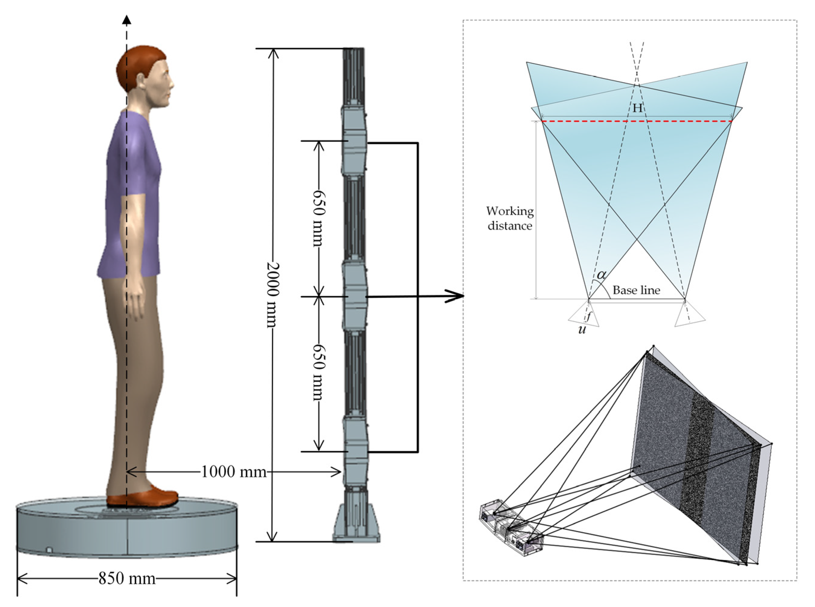
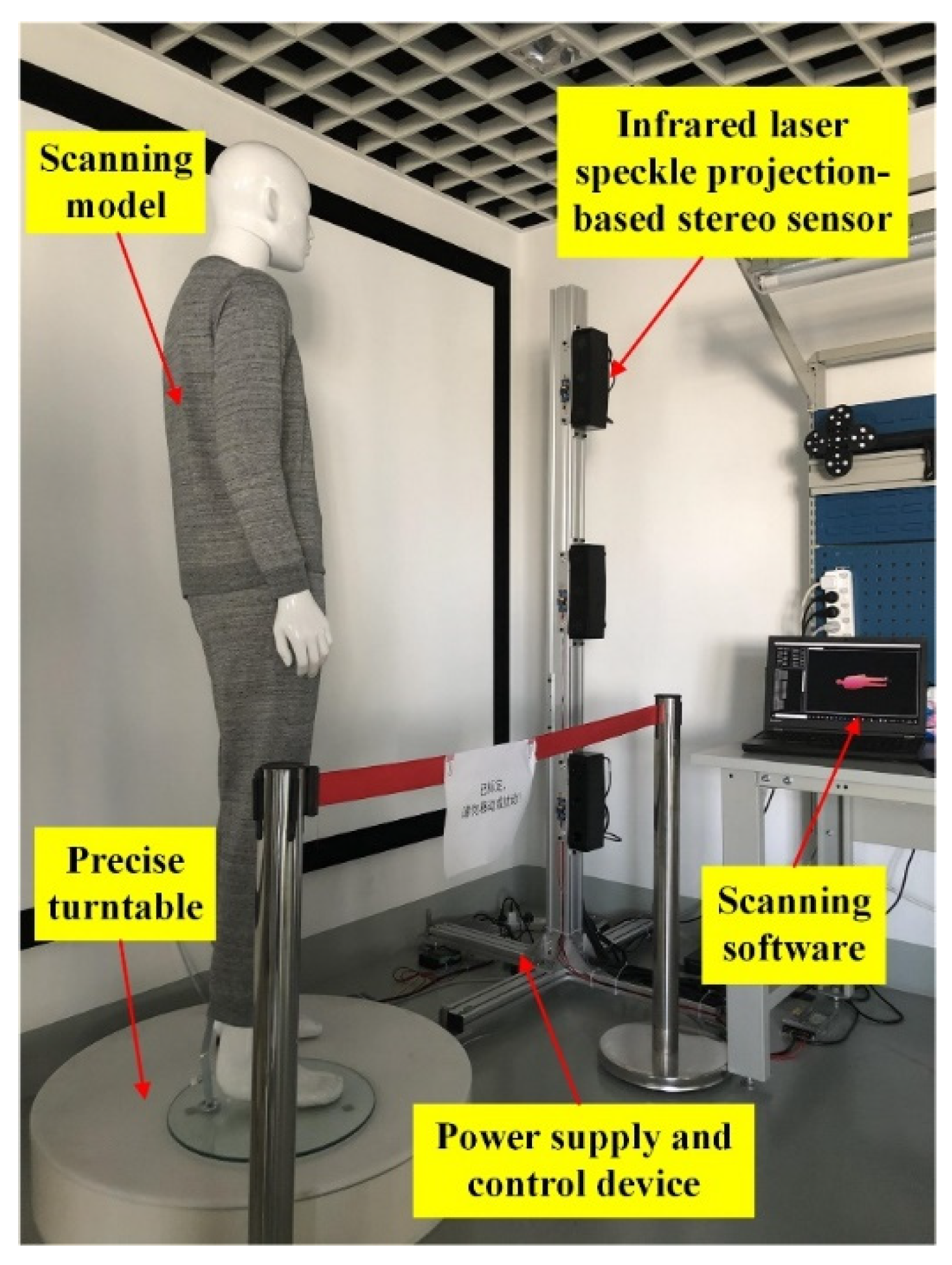
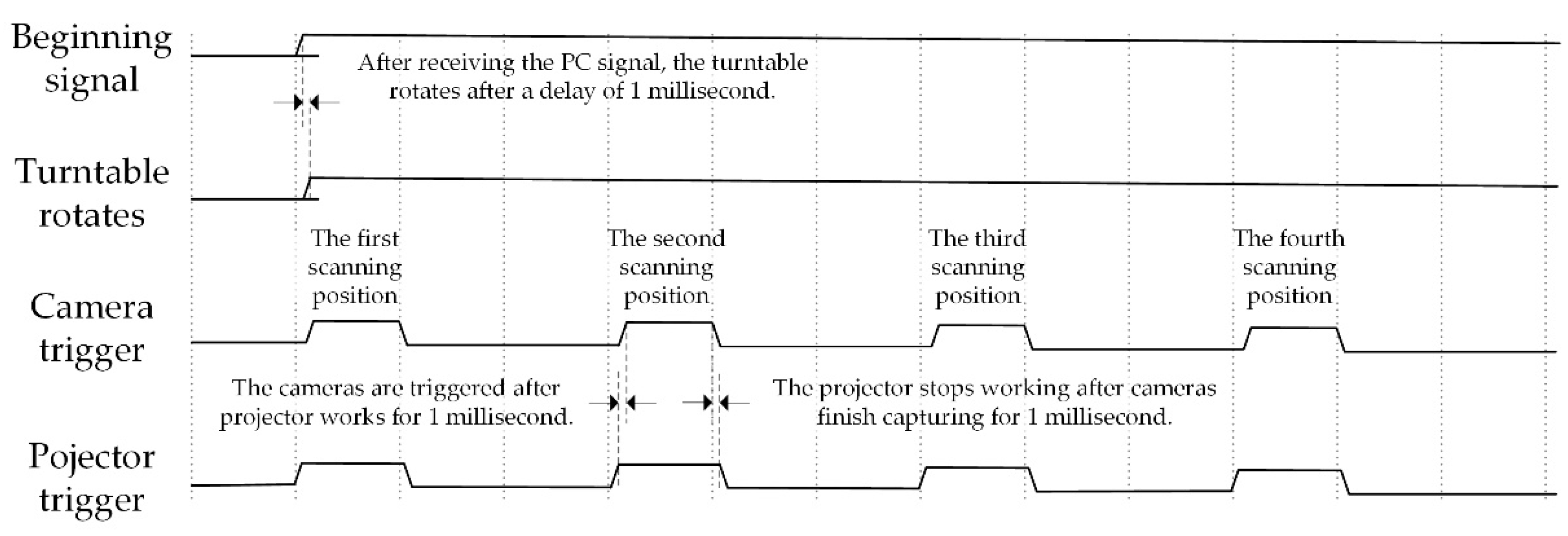
2.1. System Design

As shown in Figure 1, the designed scanning system consists of a multi-sensor column and a precision turntable, in which three infrared laser speckle projection-based binocular sensors are equidistantly distributed on the column. As an aggregate of the regions with available data (Europe, North America, Australia, and East Asia), statistics show that 95% of the sampled people born between 1980 and 1994 fall in the range from 1632 to 1936 mm [25]. In order to be able to scan more than 95% of people in China, taking the maximum height of 1950 mm as an example, according to the scanning scheme, three binocular sensors are distributed along the vertical direction, and the effective measurement height of a single sensor should reach 6500 mm. In order to achieve large scanning scenes at a possible short working distance, industrial cameras with large target size and short focal length industrial cameras are preferred on the premise of meeting the scanning precision. Therefore, half-inch cameras with half-inch target size and lens with 8 mm focal length are used in the stereo sensor. Based on field of view coincidence constraint, the designed effective measurement field of view of the stereo sensor is 680 mm × 544 mm at a working distance of 880 mm. Three binocular sensors are vertically fixed on the upright column with equal interval of 650 mm, and the height of the upright column is 2000 mm. The distance between the axle of turntable and upright post is 1000 mm, and the whole system covers an area less than 2 m2.
In this scanning scheme, the local data collected by the three binocular sensors on the column can be transformed into a global coordinate through sensor pose transformation calibration, and the data collection from head to foot of the human body at one scanning position can be realized synchronously through camera synchronous control. After image acquisition is completed at this position, the precision turntable carries the human body to rotate to the next scanning position. The coordinate transformation relationship between the two scanning positions can be obtained by the rotation angle feedback after the turntable rotating axle is calibrated. Therefore, the multi-view data of the multi-sensor and precision turntable scanning scheme can be transformed into a global coordinate, which can be automatically completed via hardware and software control. In order to shorten the scanning period as much as possible and consider the degree of vertigo that the human body can bear caused by the rotation of the turntable, the scheme plans to set four scanning positions.

2.2. Global Human Body Data Collection

2.2.1. Local Data Registration

There are four scanning positions in a scanning period, and the rotating angle of the turntable is 90° between every two positions. The starting position of the turntable is set as the first scanning position, and the rotating angles of 90°, 180°, and 270° are the second, third, and fourth scanning positions, respectively. As shown in Figure 2, the three stereo speckle sensors on the column are numbered 1, 2 and 3 from bottom to top, corresponding to the three measurement coordinate systems, namely ( O 1 X 1 Y 1 Z 1 ) , ( O 2 X 2 Y 2 Z 2 ) , and ( O 3 X 3 Y 3 Z 3 ) , respectively, where the coordinate system of speckle sensor 1 is taken as the global coordinate system of the scanning system.
The system involves two parts of data registration, one is the coordinate transformation of the point clouds collected by the three sensors on the column. Firstly, the point clouds collected by sensor 3 and sensor 2 are transformed into the sensor coordinate system of sensor 2, and then the transformed point clouds are transformed into the measuring coordinate system of sensor 1 further. The coordinate transformation processes of the two steps are as follows:
[ x 2 y 2 z 2 1 ] = M S 3 S 2 [ x 3 y 3 z 3 1 ]
[ x 1 y 1 z 1 1 ] = M S 2 S 1 [ x 2 y 2 z 2 1 ]
where M S 3 S 2 denotes the pose transformation matrix from ( O 3 X 3 Y 3 Z 3 ) to ( O 2 X 2 Y 2 Z 2 ) , and M S 2 S 1 denotes the pose transformation matrix from ( O 2 X 2 Y 2 Z 2 ) to ( O 1 X 1 Y 1 Z 1 ) . ( x 3 , y 3 , z 3 ) , ( x 2 , y 2 , z 2 ) , and ( x 1 , y 1 , z 1 ) denote the 3D points in the corresponding coordinate system. The other part is the data registration of the four scanning positions when the turntable rotates. Taking position 1 as the coordinate datum, data collected in the other three positions can be transformed into the coordinate system of first position by reversely rotating the angles of 90°, 180°, and 270° around the turntable axle, respectively. In addition, it is necessary to obtain the mathematical expression of the turntable axle in the coordinate system of ( O 1 X 1 Y 1 Z 1 ) . The registration process around the rotating axle is as follows:
[ x y z 1 ] = [ r o d r i g u e s ( n x n y n z ) θ 0 0 1 ] ( [ x 1 y 1 z 1 1 ] [ O x O y O z 1 ] ) + [ O x O y O z 1 ]
where ( x 1 , y 1 , z 1 ) denotes the 3D point collected by sensor 1 or that which has been transformed into the coordinate system of sensor 1 from the other two sensors. ( O x , O y , O z ) is the coordinate of any point on the turntable axle in the coordinate system ( O 1 X 1 Y 1 Z 1 ) , ( n x , n y , n z ) is the normal vector of the turntable axle in the coordinate system ( O 1 X 1 Y 1 Z 1 ) . The symbol θ means the rotating angle of the turntable at corresponding scanning position and r o d r i g u e s denotes the Rodrigues transformation. ( x , y , z ) is the global point coordinate after registration. To sum up the above data registration process, that is, after the scanning at each position angle is finished, the local data collected by the three sensors at each scanning position are firstly transformed into the coordinate system ( O 1 X 1 Y 1 Z 1 ) by Equations (1) and (2). And then the transformed data in ( O 1 X 1 Y 1 Z 1 ) are reversely rotated around the turntable axle by Equation (3) to realize rotary registration, thus realizing the data registration of the whole system.

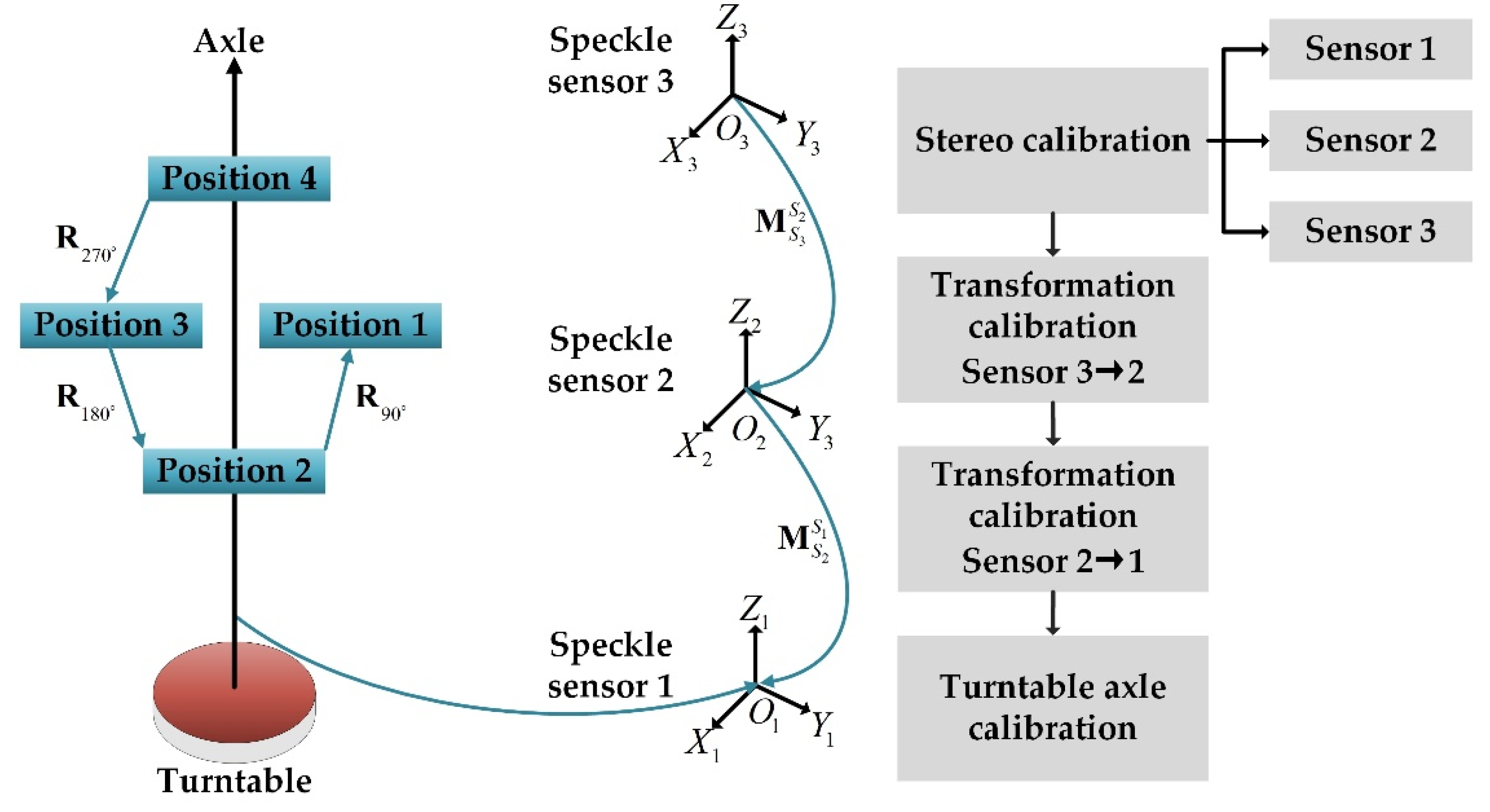
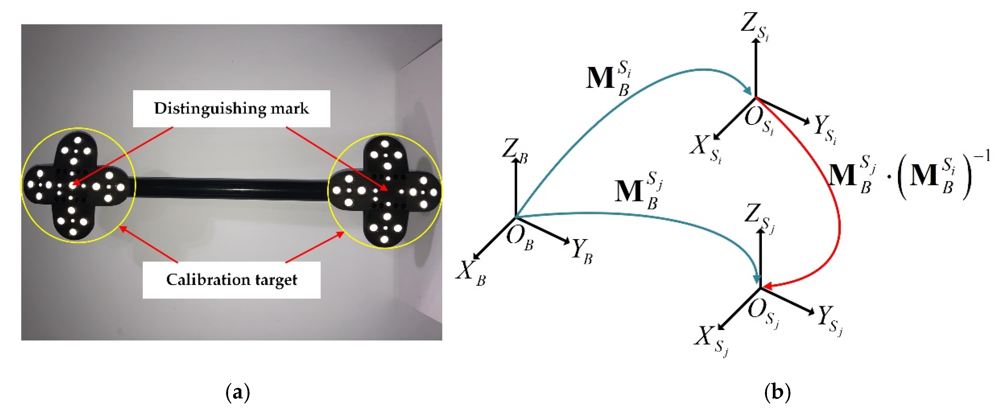
2.2.2. System Calibration

As shown in the right part of Figure 2, system calibration includes three parts. First, stereo calibration is required for each speckle sensor. Then, the pose transformation between each two sensors needs to be calibrated. Finally, the mathematical expression of the turntable axle in the coordinate system of sensor 1 needs to be calibrated. The field of view of the designed speckle sensor is 680 mm × 544 mm, a 70-inch LCD screen (LCD-70SU685A) is used to display the circular spot array image designed according to the resolution of the display in full screen, and the pixel size of the displayed image can be calculated from the physical size of the display. Then, Zhang’s plane calibration algorithm [26] is adopted for stereo calibration. Next, it is necessary to calibrate the pose transformation matrix between the two adjacent sensors because the overlapping field of view between the two adjacent sensors is very small, which cannot be directly used for pose calibration. A portable hand-held calibration rod is designed, two calibration target blocks are connected with a rigid rod to indirectly establish the common field of view between the two adjacent sensors. As shown in Figure 3a, there is a target block at each end of the designed calibration rod. The length of the connecting rod is the same as the space distance between the two sensors. During the calibration process, the target blocks at both ends should be in the respective fields of view of the two sensors. The two target blocks are composed of two kinds of circular markers with different diameters, marker identification method can refer to our previous work [13]. It should be noted that the only difference between the two target blocks is whether there is a large circular marker in the center, so the two target blocks can be automatically distinguished during calibration. As shown in Figure 3b, the calibration target coordinate system ( O 1 X 1 Y 1 Z 1 ) needs to be created, CREAFORM C-Track™ | Elite binocular tracking equipment is used to obtain the 3D physical coordinates of each circular marker. ( O S i X S i Y S i Z S i ) and ( O S j X S j Y S j Z S j ) are the coordinate systems of the two adjacent sensors, the posture transformation matrixes from the calibration target coordinate system to the two sensor coordinate systems are denoted as M B S i and M B S j . During the process of pose calibration, the 3D coordinates of circular markers on each target block are measured by the speckle sensor, and then M B S i and M B S j can be calculated according to the corresponding relationship between the measured points in the sensor coordinate and physical points in the target coordinate system. Therefore, the pose transformation matrixes from ( O S j X S j Y S j Z S j ) to ( O S i X S i Y S i Z S i ) is M B S j ( M B S i ) 1 . In order to improve the calibration accuracy, the attitude of the target bar is adjusted several times under the precondition that the field of view allows to collect unambiguous images. The physical distance between multiple target points on the target block and different target points on another target block is used to establish the optimization error function, which is then optimized by the Levenberg–Marquardt algorithm [27] to obtain optimal pose transformation matrix.
Finally, it is necessary to calibrate the position of the rotating axle in the coordinate system of sensor 1. The plane rotation measurement calibration method proposed by Ye et al. [15] is adopted, the prerequisite of the method is that the calibration target plane is perpendicular to the plane where the turntable is located. Due to the high machining and assembly accuracy of the turntable, as shown in Figure 4a, a high-precision ceramic cuboid is vertically placed on the turntable, the target plane can be regarded as a vertical relationship with the turntable plane, and the turntable is controlled to rotate for multiple angles, at each angle, sensor 1 is used to measure the surface of the plane. To determine the rotation axis, we need to determine two factors: direction vector of rotation axis and turntable center position. To calculate the direction vector of rotation axis, the measured data of the precise ceramic plate at each position are fitted into the plane firstly, and then we can obtain multiple fitted planes as shown in Figure 4b. Secondly, compute the intersection of any two fitted planes, and then calculate the average of the normal vectors of all the intersection lines, which is regarded as the normal vector of the rotating axle. In order to solve the turntable center point, we have calculated the distance from any point on the rotating axle to each fitted plane, which should be constant. Therefore, the point on the axle can be solved by minimizing the of sum of the distance squares by the Levenberg–Marquardt algorithm [27]. Up to now, the whole measurement system calibration is finished.

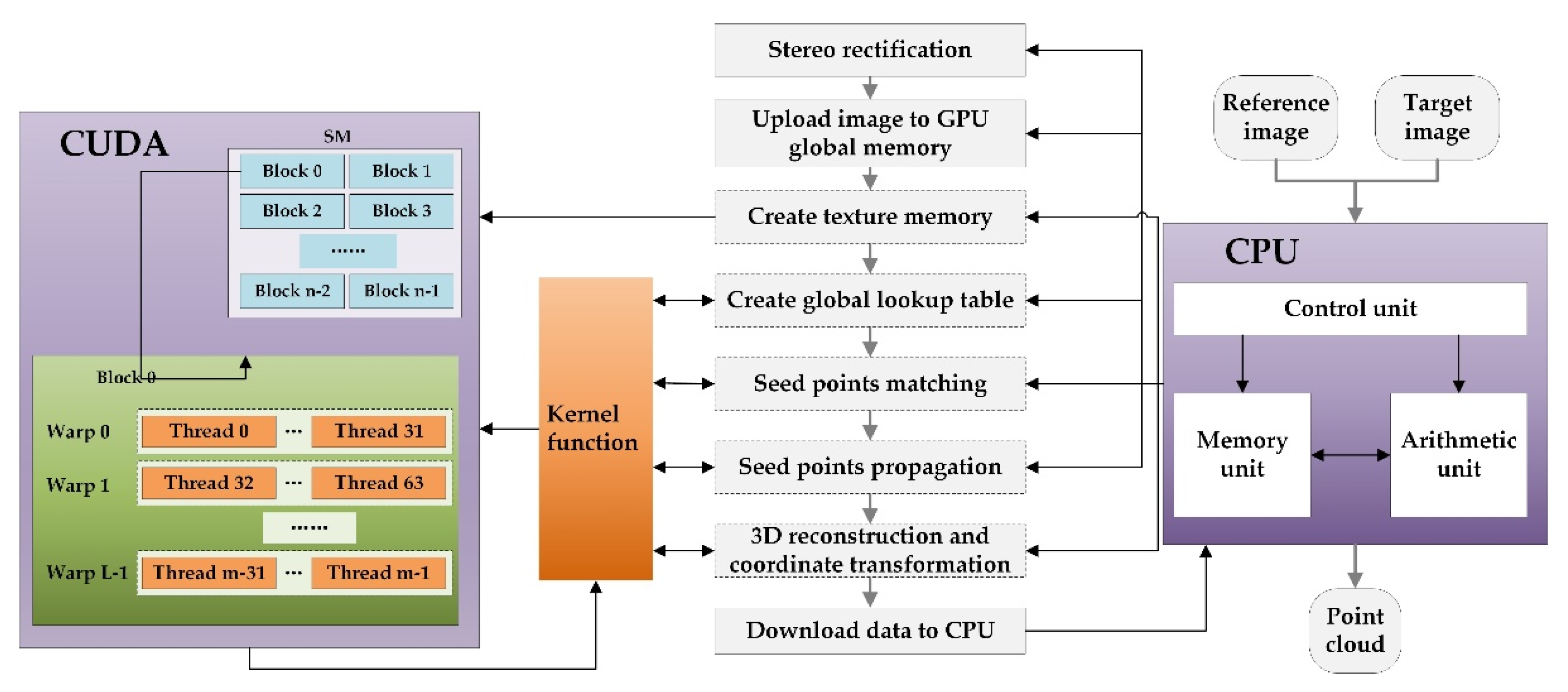
3. CUDA-Based Parallel Computing Strategy

In order to shorten the calculation period, a serial-parallel computing strategy of speckle image matching using digital image correlation is introduced in this section. According to the CUDA programming specification, the serial-parallel computing strategy shown in Figure 5 is designed to improve the efficiency of data calculation. Firstly, the left (reference) and right (target) images captured by binocular sensors are rectified on the CPU, then the corresponding global memory is created on the GPU, and the rectified images are uploaded to the designated memory on the GPU. In CUDA, the texture memory has a faster reading and writing speed than the global memory, and the rectified image pair and corresponding gradient image need to be read frequently in the matching calculation process. Therefore, texture memory has the same memory size as the global memory created on the GPU, and the global memory is banded to the texture memory. Then, the CPU sends out calculation instructions, which are mapped to the GPU through kernel function to complete the calculation processes such as establishing related global lookup table, seed points matching, seed points propagation, 3D reconstruction, and coordinate transformation. Among the above processes, the kernel function can reasonably set the dimensions of grid and block according to the calculation requirements. The data are downloaded to the CPU when the calculations are finished, and one group of local point cloud calculation is completed. As mentioned above, local point cloud computing needs to be performed 12 times in the whole measurement period, that is, the above-mentioned serial-parallel process needs to be performed for 12 times during the scanning process.

4. Experiment and Discussion

The hardware integrated multi-sensor collaborative human body scanning system is shown in Figure 6. As introduced in Section 2.1, the height of the upright column is 2000 mm, and the distance between the center of the turntable and the upright post is 1000 mm. The whole system covers an area less than 2 m2. The hardware cost of the measuring column that is composed of three sensors is about USD 2500, and the hardware cost of the turntable is about USD 1000. Therefore, the hardware cost of the proposed system is about USD 3500. In all, the proposed system is low-cost considering the area occupation cost and hardware cost comprehensively.
After power supply, the system only needs to wait to receive the beginning signal sent from a personal computer through a network cable, after that it can work automatically. The controlling sequence diagram is shown in Figure 7. The initial position of the turntable is the first scanning position. At this time, the triggering signal is sent to turn on the speckle projection module. Then six cameras in the three sensors perform synchronous hard trigger acquisitions after the three projectors work for 1 ms. When the cameras finish exposure for 1 ms, the acquisition end signal is sent to the control core panel, thus controlling the projection module to break the circuit. At this time, the first scanning process ends. When the turntable moves to the next scanning position, the above control procedure repeats. After the last scanning process finished, the control core board feeds back the ending signal to the PC. At this point, the serial-parallel computing programs are executed, and the turntable rotates back to the initial position.

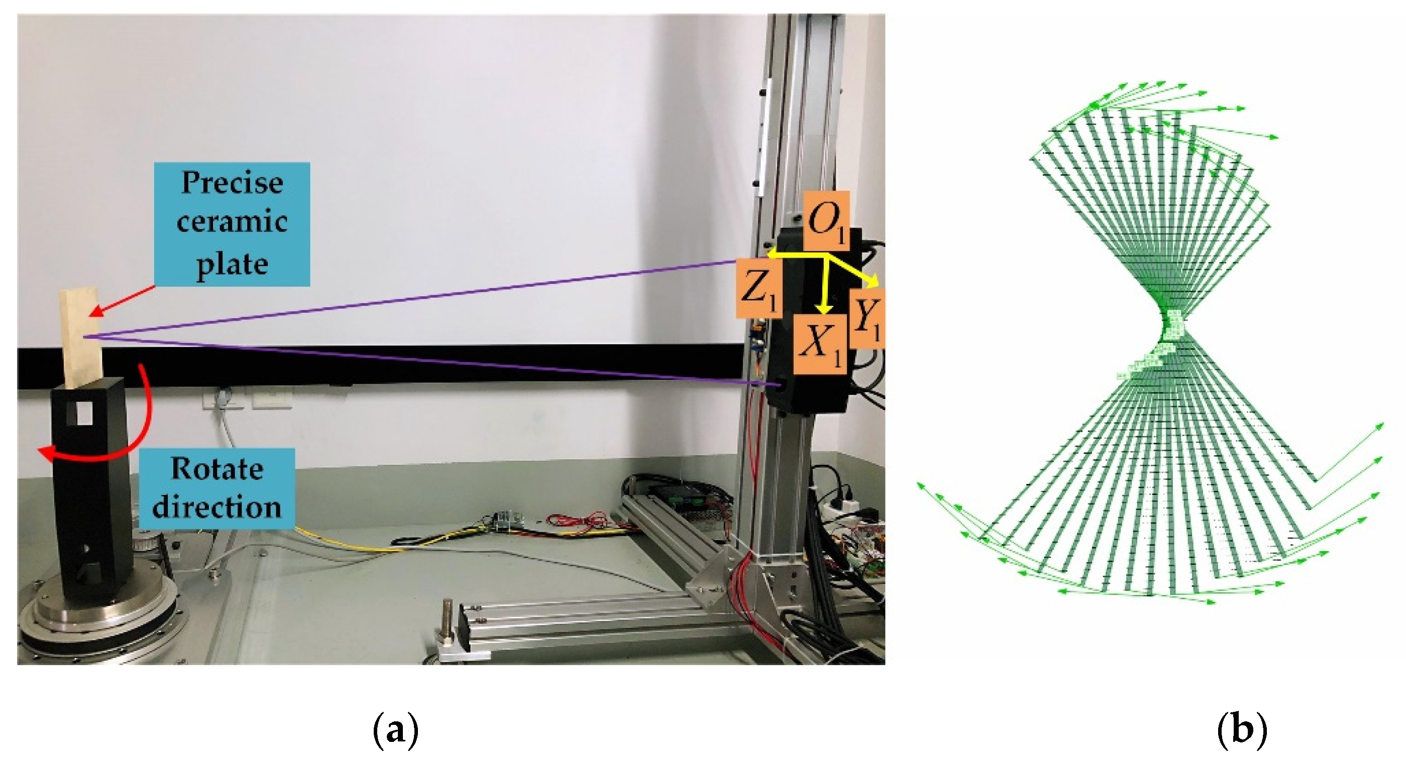
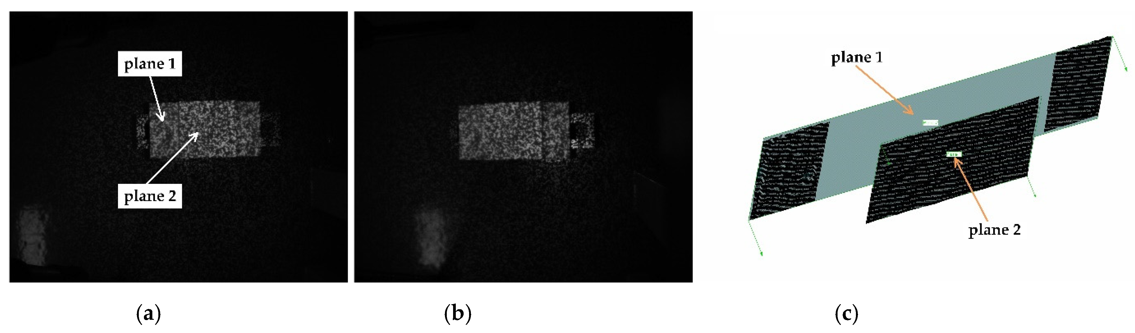
4.1. Precision Evaluation of the Stereo Sensor

In order to evaluate the measurement precision of the designed stereo sensor, as shown in Figure 8, a ceramic step block with machining tolerance of ±0.05 mm is measured by the speckle stereo sensor. The captured stereo images are shown in Figure 8a,b. As Figure 8c shows, two standard planes marked in Figure 8a are fitted from the reconstructed point cloud. The fitting standard deviations of plane 1 and plane 2 are 0.137 mm and 0.097 mm, respectively. Then, nominal depth from plane 2 to plane 1 is 20 mm. Then, ten reconstructed points are randomly selected on plane 2, the distance from the selected point to plane 1 is calculated, which is regarded as the measured depth from plane 2 to plane 2. The statistics of depth measurement error are listed in Table 1, the minimum error, maximum error, mean error are 0.136 mm, 0.278 mm, and 0.191 mm, respectively. The above results show that the measurement precision of stereo sensor is higher than 0.3 mm.

4.2. Precision and Efficiency Evaluation of the Scanning System

Before conducting the scanning experiments, the system is calibrated by the calibration method described above, then the effectiveness of the proposed scanning system is verified by three groups of anthropometric model and real human body scanning experiments, the scanning results are shown in Figure 9. For the convenience of introduction, the three groups from top to bottom in Figure 9 are indexed as I, II, and III. Index I represents the scanning result of an anthropometric model, II and III represent the scanning results of two persons. Figure 9a shows the global point clouds coordinate registration of the local point clouds obtained from 12 local views, in which different colors are used to distinguish the local point clouds. In order to suppress the registration error, the global registration function in Geomagic Studio 2012 is used to optimize the registration, the results are shown in Figure 9b. The optimized point cloud after registration is triangulated into a mesh model using the “Wrap” function of Geomagic Studio 2012, and then the convex regions and the holes are removed and filled using the “Polygons” module. Figure 9c shows the modeling renderings after point cloud encapsulation and hole repair. In Figure 9, it can be seen that the proposed system can collect the human body almost completely except for a small part of data missing in the scanning blind area and local occlusion. The average distance deviations and standard deviations of the global point clouds optimized by the function global registration function in Geomagic Studio 2012 are listed in Table 2, in which the maximum value of the average distance deviation is 1.494 mm and the maximum value of the standard deviation is 1.130 mm. The results show that the comprehensive error of point cloud stitching is less than 1.5 mm, and the measurement precision of the speckle sensor is higher than 0.3 mm. Therefore, the comprehensive scanning error of the proposed system is less than 2 mm.
In order to further evaluate the scanning efficiency, the scanning time costs of the above three groups of experiments are listed in Table 3. During the working process, when the turntable rotates from the initial position at 0 degree to the last position at 270 degrees, the images of all views of angle are collected, and the time of turntable rotation is 30 s. The image acquisition time is in the millisecond level, which is negligible. The 3D reconstruction and data registration time of point clouds in the three groups of measurement fluctuates between 31 s and 33 s, and the total time fluctuates between 61 s and 63 s. From the above results, it can be seen that the proposed system can complete the whole scanning process in about 60 s, during which the human needs to keep as still as possible during the first 30 s when the turntable rotates.
To sum up, the scanning system proposed in this paper can quickly collect dense 3D point clouds of the human body. Comparing to the anthropometric system taking images with multiple SLR cameras, it has obvious cost advantages. Additionally, near-infrared speckle measurement can effectively prevent the human eye from being stimulated by strong light and has the advantage of simple control with only a single acquisition. The scanning system only needs to receive the signal to start the measurement sent from software, and then it can automatically realize image acquisition, point cloud reconstruction, and point cloud registration. The global point cloud can be stored in various data formats according to the requirements of different fields such as clothing customization, medical assistance, and human body reminder analysis, thus facilitating different point cloud processing and modeling software to process specific requirements.

5. Conclusions

Human body 3D scanning is important for many consumption and industry fields, such as personalized intelligent customization of clothing, human body database establishment, and virtual fitting system development. In this paper, a multi-sensor digital human body scanning system based on near-infrared laser speckle projection is developed, which occupies less than 2 m2. In order to realize automatic and rapid calculation and registration of human body data, system calibration scheme and control scheme are proposed, as well, the serial-parallel computation strategy is designed based on CUDA. Finally, the effectiveness and time efficiency of the system are evaluated through anthropometric experiments. Experiment results show that the comprehensive error of scanning precision is less than 2 mm, and the complete scanning period is about 60 s.
Although the system proposed in this paper can quickly realize automatic scanning of the human body, the occlusion of limbs and the blind area of measuring field of view leads to holes in the point cloud, which needs to be filled manually by software at present. Future work should be dedicated to combine deep learning technology to realize automatic hole filling of scanned point cloud.

Author Contributions

Conceptualization, X.Y. and X.C.; methodology, X.Y. and J.X.; software, X.Y. and J.L.; data curation, X.Y., J.X., J.L. and X.C.; writing—original draft preparation, X.Y.; writing—review and editing, X.C. All authors have read and agreed to the published version of the manuscript.

Funding

This research was funded by Science and Technology Commission of Shanghai Municipality (21511104202), the National Natural Science Foundation of China (52175478), and Shanghai Industrial Coordination Leading Group Office project (2021-cyxt1-kj12).

Institutional Review Board Statement

Ethical review and approval were waived for this study, due to REASON (This work mainly aims at the application of clothing customization, the image acquisition and 3D reconstruction are carried out on the premise of people’s normal dress, which involves no biological experiments, and the whole process has no contact with people, and the system components used have no radiation or other invisible damage).

Data Availability Statement

Not applicable.

Conflicts of Interest

The authors declare no conflict of interest.

References

  1. Lu, J.M.; Wang, M.J.J.; Chen, C.W.; Wu, J.H. The development of an intelligent system for customized clothing making. Expert Syst. Appl. 2010, 37, 799–803. [Google Scholar] [CrossRef]
  2. Qiao, F.; Li, D.; Jin, Z.; Hao, D.; Liao, Y.; Gong, S. A novel combination of computer-assisted reduction technique and three dimensional printed patient-specific external fixator for treatment of tibial fractures. Int. Orthop. 2016, 40, 835–841. [Google Scholar] [CrossRef] [PubMed]
  3. Wang, L.; Cao, T.; Li, X.; Huang, L. Three-dimensional printing titanium ribs for complex reconstruction after extensive posterolateral chest wall resection in lung cancer. J. Thorac. Cardiovasc. Surg. 2016, 152, e5–e7. [Google Scholar] [CrossRef] [PubMed] [Green Version]
  4. Gosnell, J.; Pietila, T.; Samuel, B.P.; Kurup, H.K.; Haw, M.P.; Vettukattil, J.J. Integration of computed tomography and three-dimensional echocardiography for hybrid three-dimensional printing in congenital heart disease. J. Digit. Imaging 2016, 29, 665–669. [Google Scholar] [CrossRef] [PubMed] [Green Version]
  5. Ploch, C.C.; Mansi, C.S.; Jayamohan, J.; Kuhl, E. Using 3D printing to create personalized brain models for neurosurgical training and preoperative planning. World Neurosurg. 2016, 90, 668–674. [Google Scholar] [CrossRef] [PubMed]
  6. Varte, L.R.; Rawat, S.; Singh, I.; Choudhary, S.; Kumar, B. Personal protective ensemble reference size development for Indian male defence personnel based on 3D whole body anthropometric scan. J. Text. Inst. 2020, 112, 620–627. [Google Scholar] [CrossRef]
  7. Li, Z.; Di, T.; Tian, H. Research on Garment Mass Customization Architecture for Intelligent Manufacturing Cloud. E3S Web Conf. 2020, 179, 02125. [Google Scholar] [CrossRef]
  8. Kolose, S.; Stewart, T.; Hume, P.; Tomkinson, G.R. Cluster size prediction for military clothing using 3D body scan data. Appl. Ergon. 2021, 96. [Google Scholar] [CrossRef] [PubMed]
  9. Jung, J.; Yoon, S.; Ju, S.; Heo, J. Development of Kinematic 3D Laser Scanning System for Indoor Mapping and As-Built BIM Using Constrained SLAM. Sensors 2015, 15, 26430–26456. [Google Scholar] [CrossRef]
  10. Chi, S.; Xie, Z.; Chen, W. A Laser Line Auto-Scanning System for Underwater 3D Reconstruction. Sensors 2016, 16, 1534. [Google Scholar] [CrossRef] [PubMed] [Green Version]
  11. Chen, X.; Xi, J.; Jin, Y.; Xu, B. Accuracy improvement for 3D shape measurement system based on gray-code and phase-shift structured light projection. Int. Soc. Opt. Photonics 2007, 6788, 67882C. [Google Scholar]
  12. Cheng, J.; Zheng, S.; Wu, X. Structured Light-Based Shape Measurement System of Human Body. In Proceedings of the Australasian Joint Conference on Artificial Intelligence; Springer: Berlin/Heidelberg, Germany, 2011; pp. 531–539. [Google Scholar]
  13. Yang, X.; Chen, X.B.; Zhai, G.K.; Xi, J.T. Laser-speckle-projection-based handheld anthropometric measurement system with synchronous redundancy reduction. Appl. Opt. 2020, 59, 955–963. [Google Scholar] [CrossRef] [PubMed]
  14. Kieu, H.; Pan, T.; Wang, Z.; Le, M.; Nguyen, H.; Vo, M. Accurate 3D shape measurement of multiple separate objects with stereo vision. Meas. Sci. Technol. 2014, 25, 1–7. [Google Scholar] [CrossRef]
  15. Ye, Y.; Zhan, S. An accurate 3D point cloud registration approach for the turntable-based 3D scanning system. In Proceedings of the 2015 IEEE International Conference on Information and Automation (ICIA), Lijiang, China, 8–10 August 2015. [Google Scholar]
  16. Liang, Y.B.; Zhan, Q.M.; Che, E.Z.; Chen, M.W.; Zhang, D.L. Automatic Registration of Terrestrial Laser Scanning Data Using Precisely Located Artificial Planar Targets. IEEE Geosci. Remote. Sens. Lett. 2014, 11, 69–73. [Google Scholar] [CrossRef]
  17. Zhang, W.; Han, J.; Yu, X. Design of 3D measurement system based on multi-sensor data fusion technique. In Proceedings of the 4th International Symposium on Advanced Optical Manufacturing and Testing Technologies: Optical Test and Measurement Technology and Equipment, Chengdu, China, 19–21 November 2008; p. 728314. [Google Scholar]
  18. Chen, F.; Chen, X.; Xie, X.; Feng, X.; Yang, L. Full-field 3D measurement using multi-camera digital image correlation system. Opt. Lasers Eng. 2013, 51, 1044–1052. [Google Scholar] [CrossRef]
  19. Wang, P.; Zhang, L.Y. Self-registration shape measurement based on fringe projection and structure from motion. Appl. Opt. 2020, 59, 10986–10994. [Google Scholar] [CrossRef] [PubMed]
  20. Pesce, M.; Galantucci, L.M.; Percoco, G.; Lavecchia, F. A Low-cost Multi Camera 3D Scanning System for Quality Measurement of Non-static Subjects. Procedia Cirp 2015, 28, 88–93. [Google Scholar] [CrossRef] [Green Version]
  21. Leipner, A.; Baumeister, R.; Thali, M.J.; Braun, M.; Dobler, E.; Ebert, L.C. Multi-camera system for 3D forensic documentation. Forensic Sci. Int. 2016, 261, 123–128. [Google Scholar] [CrossRef] [PubMed]
  22. Wang, L.; Wu, F.C.; Hu, Z.Y. Multi-Camera Calibration with One-Dimensional Object under General Motions. In Proceedings of the 2007 IEEE 11th International Conference on Computer Vision, Rio de Janeiro, Brazil, 14–21 October 2007. [Google Scholar]
  23. Kumar, R.K. Simple calibration of non-overlapping cameras with a mirror. In Proceedings of the 2008 IEEE Conference on Computer Vision and Pattern Recognition, Anchorage, AK, USA, 23–28 June 2008; pp. 1–7. [Google Scholar]
  24. Yang, T.; Zhao, Q.; Quan, Z.; Huang, D. Global Calibration of Multi-Camera Measurement System from Non-Overlapping Views; Springer: Cham, Switzerland, 2018. [Google Scholar]
  25. Roser, M.; Appel, C.; Ritchie, H. Human Height. Available online: https://ourworldindata.org/human-height (accessed on 16 November 2021).
  26. Zhang, Z. A Flexible New Technique for Camera Calibration. IEEE Trans. Pattern Anal. Mach. Intell. 2000, 22, 1330–1334. [Google Scholar] [CrossRef] [Green Version]
  27. Wilamowski, B.M.; Hao, Y. Improved Computation for Levenberg–Marquardt Training. IEEE Trans. Neural Netw. 2010, 21, 930–937. [Google Scholar] [CrossRef] [PubMed]
Figure 1. Scheme design for human body 3D scanning.
Machines 09 00299 g001
Figure 2. Schematic diagram of data registration and system calibration.
Machines 09 00299 g002
Figure 3. Pose transformation calibration for two adjacent sensors: (a) handheld target calibration rod; (b) calibration diagram.
Machines 09 00299 g003
Figure 4. Turntable axle calibration: (a) schematic diagram; (b) measurement result of rotary plane.
Machines 09 00299 g004
Figure 5. Schematic diagram of CUDA-based serial-parallel computing strategy.
Machines 09 00299 g005
Figure 6. Multi-sensor collaborative human body scanning system.
Machines 09 00299 g006
Figure 7. Controlling sequence diagram of the scanning system.
Machines 09 00299 g007
Figure 8. Measurement of a ceramic step block: (a) left image; (b) right image; (c) reconstructed point cloud.
Machines 09 00299 g008
Figure 9. Human body scanning results: (a) point clouds of registration by system calibration; (b) point clouds after registration optimization; (c) 3D model.
Machines 09 00299 g009
Table 1. Statistics for depth measurement error of the ceramic step block.
Point index12345678910
Depth error 10.1650.1360.1710.1500.2510.2780.1800.1550.2590.161
1 Unit: mm.
Table 2. Statistics for average distance deviations and standard deviations of global point clouds after optimization of registration.
IIIIII
Average distance deviation 11.1541.4511.494
Standard deviation 11.0260.9371.130
1 Unit: mm.
Table 3. Statistics for scanning time cost.
Time of
Turntable Rotation 1
Time of
3D Reconstruction and Registration 1
Total Time 1Point Number
I3032.7462.74628,939
II3031.3361.33567,893
III3031.6561.65614,126
1 Unit: s.
Publisher’s Note: MDPI stays neutral with regard to jurisdictional claims in published maps and institutional affiliations.

