1. Introduction
Smart production systems in the dairy industry cover several activities, such as material processing, loading, unloading, transferring, storing, sequencing, monitoring, and controlling. Loading and unloading activities are associated with setting or replacing the parts on a machine. Material transferring is dealing with conveying and protecting the transferred bottles between workstations. Sequencing is dealing with receiving orders from the customers in which bottles of different volumes are processed. System controlling is considered as the nerve system of the production system, in which all the production activities are coordinated. In addition to that, system monitoring is dealing with obtaining precise data from sensors remotely and supplying it to the controlling system.
The utilization of modern information technologies, such as the cyber-physical systems or the Internet of things, and the processing of vast amounts of data (big data) forms the basis for the concept known as industry 4.0 or “IR4.0” [
1,
2]. The fourth industrial revolution is considered the upcoming significant technology trend as it allows end users (customers) to receive their products based on their expectations in terms of product varieties and quantiles (i.e., mass customization) [
3]. Existing technologies should be able to support the mass customization implementation in food (i.e., dairy) industries [
4]. Basically, smart products that interact with consumers [
5] and introducing smarter, more efficient processes are enablers that could facilitate this implementation [
4].
Advances in sensors technology have the potential to collect, analyze, and use the information of custom-made products in a short time, with high accuracy and precision. The production line is digitalized with IoT sensors that drive the work and operation flow. Therefore, IoT sensors generate a considerable amount of data [
6], and this can be accomplished by collecting various kinds of data about the production processes and sending those data to the cloud for analytics and predictions, or on an edge device for a real-time response [
7].
With the increasing popularity of IR4.0 in both academia and the industrial sectors [
8], the Industrial Engineering Department (IED) at King Saud University (KSU) invested considerable efforts focusing on building a state-of-the-art technological production prototype based on the principles of IR4.0 (i.e., mass customization production line) [
8].
This prototype is utilized to be an instrument directing research graduates towards innovation. After the successful completion of the first phase of building a smart automated yogurt production line, the next step was developing a smart product [
9]: a product that interacts with the production line and establishes a link between a customer and the manufacturer. A customer prefers a transparent catalog, displaying product prominence, and a smart product interrelates essential data at all levels of production and portrays high standards of fabrication. We assimilate NFC (near field communication) tags with our yogurt bottles to bridge the communication between the product, production line, and customer. This complements our intention of adding real-time complexities to build a sophisticated yogurt plant, which additionally benefits the quantity and quality in the process of making flavored yogurt.
In this article, we propose a control system for remodeling and improving a previously existing YFM to reflect the latest technological developments in IR4.0. The project implements and combines several concepts of industry 4.0 (i.e., a smart product using an NFC as an enabler for IR4.0 [
10], Internet of things sensors for smart monitoring and control [
11], and industrial Internet of things (IIoT)). In addition, another controller was added (Raspberry Pi 4 Model B) to the system to control the NFC signal and ease communication with the WAGO PFC controller. Applying this, we demonstrate system interoperability. In order to complete all the working processes smartly and automatically, the aforementioned processes are implemented throughout the YFM to avoid any human intervention.
Promising Technologies to Overcome the Existing Limitations
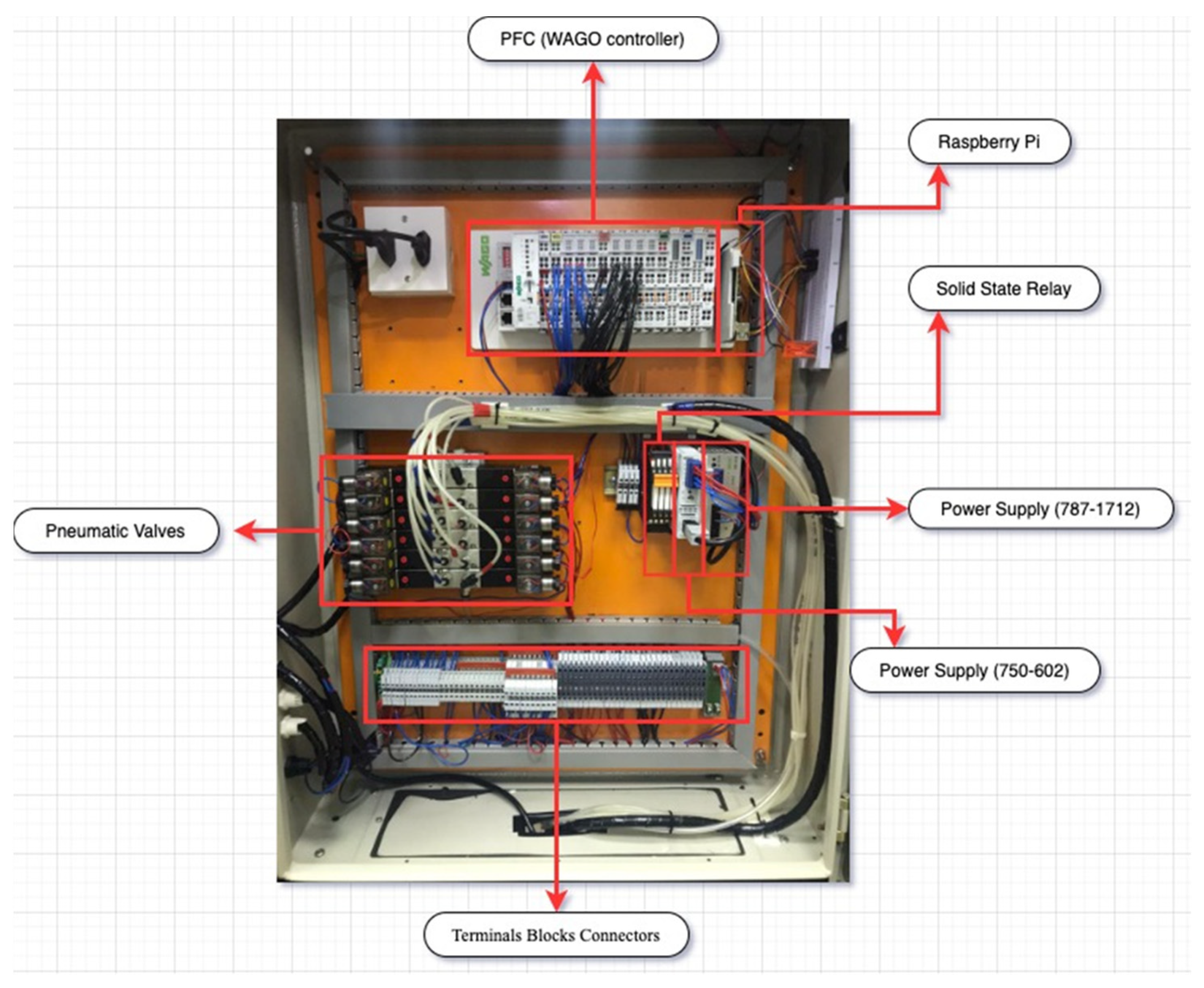
The previous system was a semi-automatic filling machine due to the existence of human intervention in some parts of the processes (ex., feeding the process with empty yogurt bottles and transferring the filled bottles to the corresponding positions in the refrigerated warehouse). In addition to that, one of the limitations in the previous phase was that each yogurt bottle had a color code for flavor identification and an optical sensing for quantity grouping. The corresponding color sensor detects the bottle’s color and a related pneumatic piston stops the bottle at the desired flavor station (e.g., strawberries are red, so red is associated with the flavor of strawberry). Once the desired yogurt flavor filling process finishes, the next empty bottle enters the process chain. Finally, the previous system did not focus on the safety dimension, so a control panel comprising all the electronic devices that provide signals to direct the operations was mounted on the YFM frame. In order to maintain the safety of the entire system and people, an electrical control panel, as shown in
Figure 1, has been installed.
2. Architecture of the Production Line
The Laboratory of Computer Integrated Manufacturing, Industrial Engineering Department, King Saud University, Saudi Arabia provided a mass customization filling yogurt machine, which is mainly designed to handle the orders received from customers [
10]. The rearrangement of the conveyor belt with its base plate from an L to U shape was completed. As per the core objectives of our research team, The YFM achieved its first step by using a 3D printer to manufacture the conveyor system’s missing mechanical component [
10]. The precise dimensions from the CATIA software eased this process and led to a successful closed loop function of our conveyor system primarily.
2.1. An Overview of the Preceding Prototype
The process of filling yogurt in bottles with desired flavors with some human intervention was the first phase. To accomplish this filling process, an empty bottle has to pass through a minimum of five stages. Though a stopover at every stage was time-consuming, this learning factory was able to execute three types of production processes (repetitive, discrete, and customized) in a single production line. The performance of each type of production process was studied. Utilizing IR4.0 concepts in the next stage of developing a smart product from a conventional linear development process to a customized smart process was analyzed.
2.2. Consequent Stage of Development
A semi-automatic conveyor belt that often required human intervention to complete the production processes was shifted to a fully automated mode. The focus was to enhance the production rate and reduce the process time by utilizing IR4.0 technology’s enablers, and the goal was accomplished successfully. Therefore, a production line resembling the real-time sequences of an industrial bottle filling plant was demonstrated by incorporating the concepts of IR4.0.
In this phase, we have simplified the color identification and quantity categorization utilizing near field communication technology (NFC). In the previous phase, each yogurt bottle had a color code for flavor identification and optical sensing for quantity grouping. Moreover, they had to be manually stacked on the base plate of the conveyor belt. This human intervention step was simply skipped by using a robotic arm. The NFC technology removed the colored bottles from the production line, replacing them with uniform bottles fastened with pre-written NFC tags.
2.3. New Smart Design Layout
Introducing a proper layout was the first challenge to eliminating the human–machine interaction in the yogurt filling machine. The task of loading an empty bottle and unloading the yogurt-filled bottle by a human was assigned to a Fanuc LR Mate 200ic robotic arm. The robotic arm was programmed so it would gently lift the NFC-tagged empty bottles and place them steadily in the empty base plate. In parallel, it would remove the yogurt-filled bottles from the base plate waiting at the end terminal of the conveyor belt, maneuvering them into the refrigerated warehouse.
Reducing the stages of the yogurt filling process without eliminating the task of production was the second issue confronted. The whole yogurt filling process was unified as a single stage.
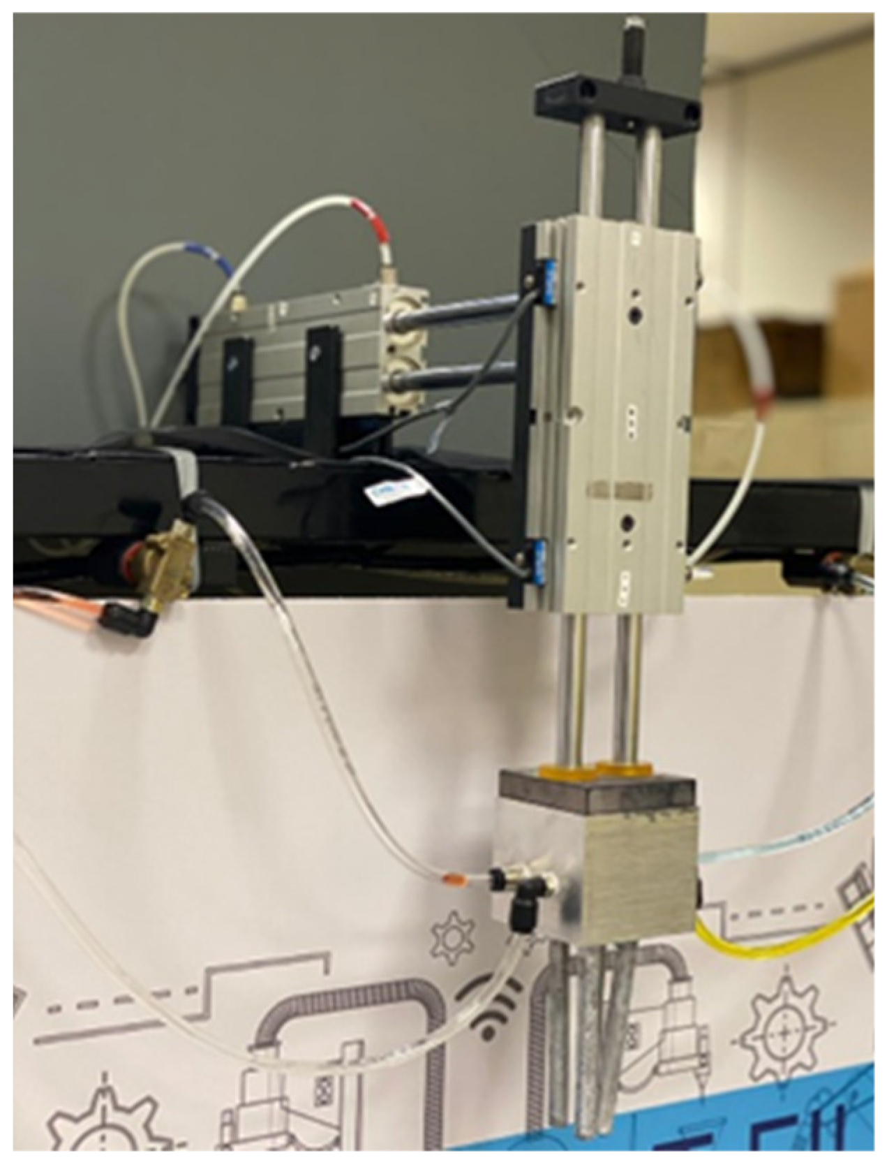
Figure 2 shows the new unified liquid head nozzle metal block that was designed adopting SolidWorks software. A stainless-steel metal block precisely underwent a drilling and milling processing at our lab and was transformed into a unified liquid filling nozzle. With high precision tools, our team designed the metal block that connected the tubes of the flavored yogurt containers and the filling nozzles of the yogurt bottles.
2.4. Recent Hardware Add-Ons
A pneumatic linear slide working in two directions horizontally and vertically was mounted over this unified filling nozzle in order to have a streamline flow of yogurt into the empty bottle. By implementing this pneumatic manipulator arm (
Figure 2), three filling stages have been combined into one, facilitating the process as a single step.
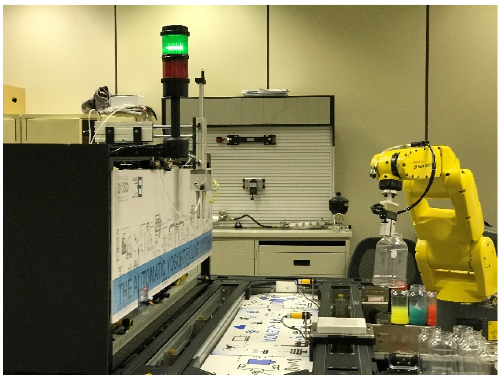
Moreover, an industrial robotic arm, manufactured by FANUC, was installed to achieve fully automated operation. The empty yogurt can is transferred to the base plate waiting at the start station via the robotic arm (
Figure 3). As the sensor detects the bottle, a control signal is sent to the controller to start moving the plate.
2.4.1. Near Field Communication (NFC)
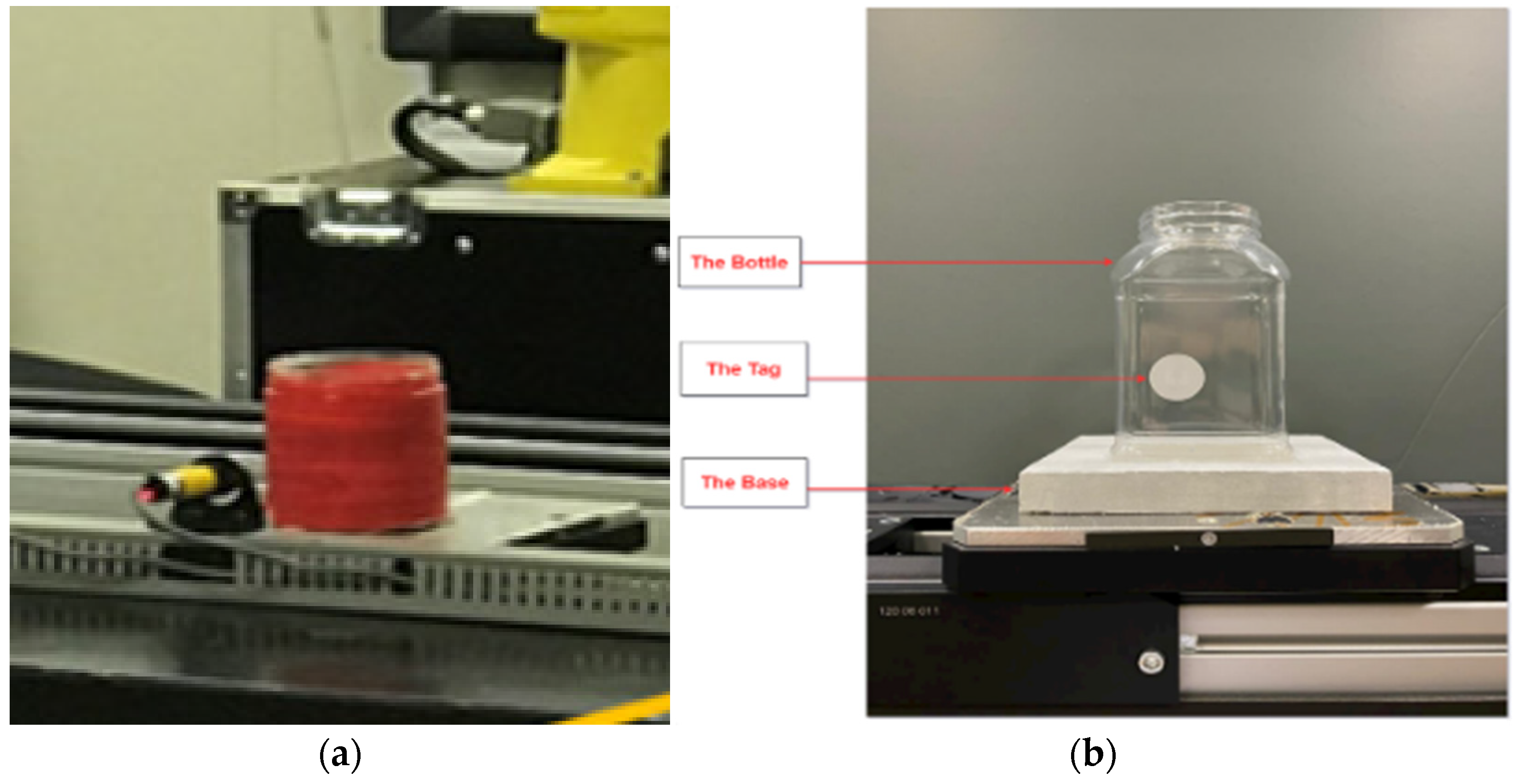
The next challenge confronted by the research team was to introduce a unique technique for the product identification method. The research team decided to implement an NFC to increase security and efficiency. According to the previous phase, as shown in
Figure 4a, a color sensor (i.e., proximity sensor) was used to identify the flavor of the yogurt bottles. Moreover, the yogurt containers had to be color-wrapped appropriately for the color sensor to identify and process the command signal to the PFC. Introducing and implementing NFC tags for the product identification and filling the desired flavor and quantity became easier, as shown in
Figure 4b. It was also beneficial to the consumer to read the NFC tag data and obtain information about the yogurt bottle expiry date and time of filling using any latest android gadget.
Our team opted to use an NFC tag rather than a radio frequency identification (RFID) tag because of its enormous advantages in developing smart products, in addition to its ease of use, which makes the solution suitable. Moreover, reading information from NFC tags is effortless and contactless with the transfer of the data/signal between the reader and tag at 13.56 MHz using NFC technology [
11]. By using NFC tags, a uniformity in the yogurt bottles appeared in the production line. This step put an end to the colored bottles for different flavors. This paved the first way for our smart product (flavored yogurt bottle) to communicate with the production line and convey a desired command to the PFC to send command signals as per the logic sequence to the filed devices. Moreover, the product development information at every stage of production can be analyzed.
In order to read and write data in the NFC tag, we obtained a PN532 breakout board, an NFC module manufactured by Adafruit. To power the PN532 board, an FTDI chip was utilized. The desired information is written and pasted on an empty bottle, which, in turn, is transferred to the conveyor belt by the robotic arm. In the next station, this PN532 NFC tag reader module decoded the tag information from the bottle in accordance with the customer order (quantity and flavor). The NFC tag is placed adjacent to the conveyor track so as to capture and transmit data to Raspberry Pi, then it will give commands to the WAGO PFC. The Raspberry Pi was programmed to provide digital control signals to define the required quantity and variety of the product. To accomplish a decentralized task, a programmable field controller (PFC) was procured from WAGO Kontakttechnik GmbH & Co. KG [
12]. Safety aspects during production process were included in order to avoid any accidents during product development. After deploying the required configuration on the shop floor, the next challenge was interconnecting data with different memory values and translating them in a perfectly synchronized production sequence to build a customized product with varying flavors. The developed system is also designed to manage orders of different volumes of plain yogurt and flavor mixtures. Moreover, the YFM typically consists of the following main components, illustrated in
Figure 5.
2.4.2. Hardware and Peripheral Components
In the second phase, a few devices and components were added to the system to improve its functionality, such as: (i) diaphragm pumps were connected to the unified filling nozzle and yogurt flavor storage tanks in order to increase the flow rate; these pumps sucked the filling liquid and delivered a streamline flow and passed the liquid yogurt to the empty bottles via the unified head nozzle; (ii) solenoid valves are electrically controlled valves used for releasing the liquid for a defined time interval to fill up the required quantities and sizes of both plain yogurt and flavored; and (iii) a pneumatic manipulator arm to align the position of the filling nozzle in front of the yogurt can in order to avoid any spillage of the liquid (yogurt). The conveyor belt runs continuously when the start pushbutton is pressed and set to the ON state, where the conveyer belt shuts down in the case of an emergency stop pushbutton being pressed.
3. Program Paradigms
This section deals with the design and development of a fully automated production line, i.e., yogurt filling system, to facilitate the entire operations and apply the IR4.0 understandings. The proposed system has been implemented in accordance with IR4.0 standards for rendering human intervention to a very minimum level. We considered an experimental strategy as shown in
Table 1. The production strategy works on different product varieties that happen after an order is placed by a customer through the customer order platform to identify the customer’s order information (amount and flavor; for example, five different bottle sizes of plain yogurt with blueberry flavor).
3.1. Automated Process of the Yogurt Filling System
The yogurt filling system consists of a conveyor belt and a unified liquid head nozzle, which has three nozzles for plain yogurt (P) and two flavors (FLAV1, FLAV2). Accordingly, four different combinations are available based on the orders’ cases reference options (CR), as shown in
Table 2. After placing an empty bottle on the specific location over the conveyor belt, the plain yogurt and the two flavor nozzles feed the empty bottles through three diaphragm/two-way solenoid valves that can be actuated using three outputs relays (O_S+ for plain yogurt, O_S1+ for FALV1, and O_S2+ for FLAV2), respectively. Filling the bottles can be carried out by controlling the diaphragm pump/solenoid valve through three different timers for each bottle volume. Three different yogurt bottle sizes used are 300, 600, and 900 mL, respectively. Hence, nine timers will be used for all three-bottle volumes.
The plate with an empty bottle is then detected by a proximity sensor (SW1) and stopped at the filling station over the conveyer belt using a pneumatic double acting cylinder (X). The diaphragm filling head nozzle in this station will adjust itself to the filling position and fill the bottle by moving downward towards the bottle using a double acting cylinder (Y). The filling process is carried out depending on the information received from the NFC module. Both pneumatic cylinders are actuated using a 5 × 3-solenoid valve and two return springs. Each valve has two solenoids for two extreme positions (SOL_X+, SOL_X−, SOL_Y+, and SOL_Y−). Reed switches are mounted on the two extreme positions for each cylinder for feedback signals (x+, x−, y+, y−).
3.2. Rellay Ladder Diagram Design Based on Cascade Method
The CASCADE method is considered as one of the common PLC programming techniques used in the industry to develop the relay ladder diagram for industrial automation. The technique is straightforward for a quick relay ladder diagram. In this technique, five different machine sequences are common in industrial applications. These machine sequences are typical as follows: single path machine sequence, multi-path (parallel) machine sequence, a parallel path with an alternative option, machine sequence with an option of bypassing certain steps, and machine sequence with the option of repeating certain steps. In general, industrial machine sequences are either based on one of the above-mentioned sequences or a combination of them.
Based on the CASCADE technique, the relay ladder diagram is divided into two modules: the flip-flop model and output module. The basic function of the flip-flop module is covering the machine sequencing processes, while the actuators (i.e., machine outputs) are driven by the output module based on the sequence stated in the flip-flop module. At the simplest level, it divides the YFM sequences into a pre-defined number of groups, where each group has its own flip-flop with set and reset input signals. The groups were created based on the fact that there are no conflict signals combined in the same groups. Generally, you set the first flip-flop (i.e., group) using the START button, while you reset the group using the next flip-flop. Resetting the last group is completed by approaching the last control signal within the machine sequence.
Two types of output signals can be generated by the output module: sustain and non-sustain output signals. Sustain outputs usually do not have a mechanical memory; therefore, the signal will be maintained to sustain the output. On the other hand, the non-sustain output has a mechanical memory; therefore, there is no need to maintain the output due to the conserved signal by the memory.
3.3. Yogurt Filling Machine Sequence
An overview of the machine sequence is shown in
Figure 6 below. In case of the START button being pressed, a repeat cycle begins as soon as a bottle of yogurt is detected (i.e., sw1 = true) and a repeat cycle switch is activated (i.e., xp = true). Additionally, when the START button is pressed, the conveyor belt will also switch to the on state; during this time, the motor will be in a state of off if the emergency stop button (E.stop) is pressed.
Furthermore, when a yogurt bottle is detected, selector switches FLV1 and FLV2 are also used to obtain the flavors in order to determine the customer’s inquiry, as shown in
Table 1. According to the current situation, there are four possible selectin flavor cases:
CR1: Customer orders only plain yogurt
CR2: Customer orders plain yogurt and FLAV 1
CR3: Customer orders plain yogurt and FLAV 2
CR4: Customer orders plain yogurt, FLAV 1, and FLAV2
If a bottle of yogurt is detected (sw1 = true), the lower pneumatic cylinder X is set to the upward position (X+) in order to lift the pallet from the conveyor for holding the baseplate. Afterwards, the integrated filling head nozzle is lowered using the pneumatic cylinder (Y+).
A specific time is assigned to the filling head nozzles based on the volume of the yogurt bottle and consumer flavor inquiry for each of the four flavor cases shown in
Table 2. After finishing the filling processes, the filling head cylinder moves upward (Y−); consequently, the cylinder X is lowered to allow the bottle pallet to be moved by the conveyor (X−). If there is another yogurt bottle detected via (sw1 = true), this process will be repeated. On the other side, the filling process is suspended or by-passed if there is no yogurt bottle detected (sw1 = false).
3.4. Design of a Yogurt/Flavor Combination Machine
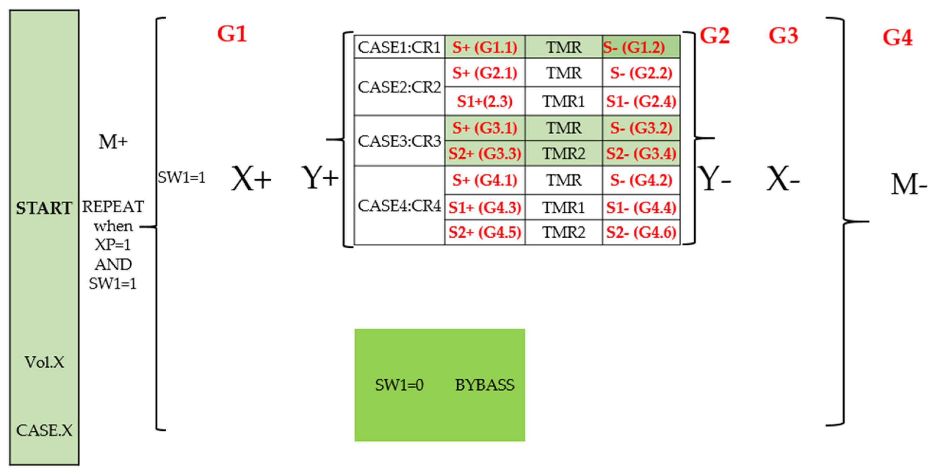
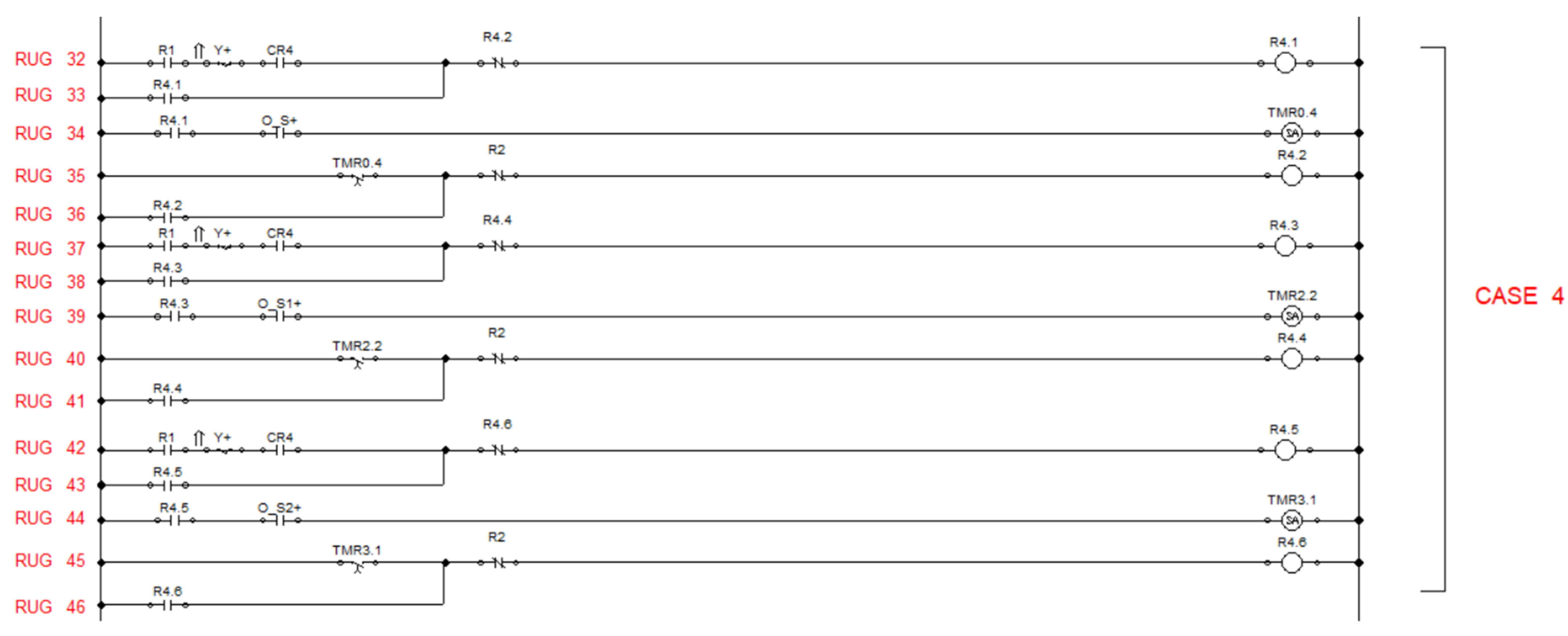
As a result of the CASCADE method, the machine sequence consists of four main groups (G1, G2, G3, G4). Based on the yogurt/flavor combinations, four possible cases (CASE 1 through CASE 4) were assigned as sequence subgroups as shown in
Figure 3.
CASE 1 consists of just plain yogurt without a flavor; hence, the single path machine sequence is used (S+, S−) with subgroups G1.1, and G1.2.
CASE 2 is sequenced with parallel paths, which include base yogurt and one flavor, where the machine sequence is used as with subgroups . The machine sequence for CASE 3 is the same as for CASE 2 with parallel machine sequence with subgroups .
Finally, CASE 4 is sequenced with three parallel paths, which include base yogurt and two flavors, where the machine sequence is used as with subgroups .
3.5. Assigned Output/Input Signals for YFM Sequence
Simulation is done using FESTO FluidSIM-MecLab software. Sustain signals are assigned to three control output signals. The two-way solenoid valve and the diaphragm pump will be actuated by each output. The symbolic addresses for the three outputs are O_S+ (plain yogurt), O_S1+ (FLAV 1), and O_S2+ (FLAV 2).
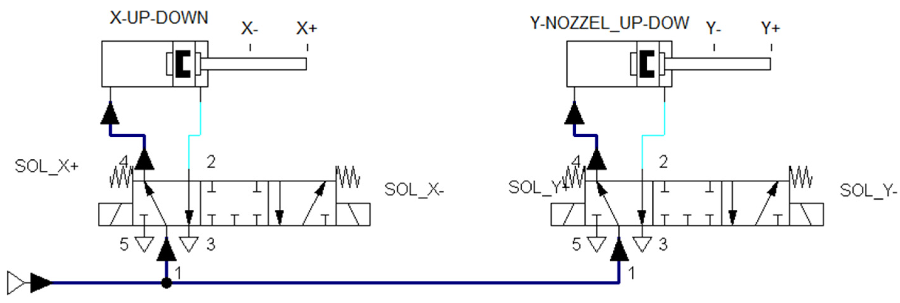
Non-sustain signals are assigned to two pneumatic cylinder solenoid valves: two solenoids for actuating Valve X and, similarly, two solenoids for actuating Valve Y. The symbolic address outputs Sol_X+ and Sol_X− are assigned for actuating valve X. Double acting X and Y cylinders are actuated by two 5x3 valves with return springs and solenoids.
Finally, two input control feedback signals are triggered through two reed detectors at the two extreme positions of the cylinder. The symbolic addresses for these two inputs are X+, and X−. In the same way, it is applied to cylinder Y. The cylinders X and Y move forward when solenoids SOL_X+ and SOL_Y+ are energized, as shown in
Figure 7.
3.6. Relay Ladder Diagram
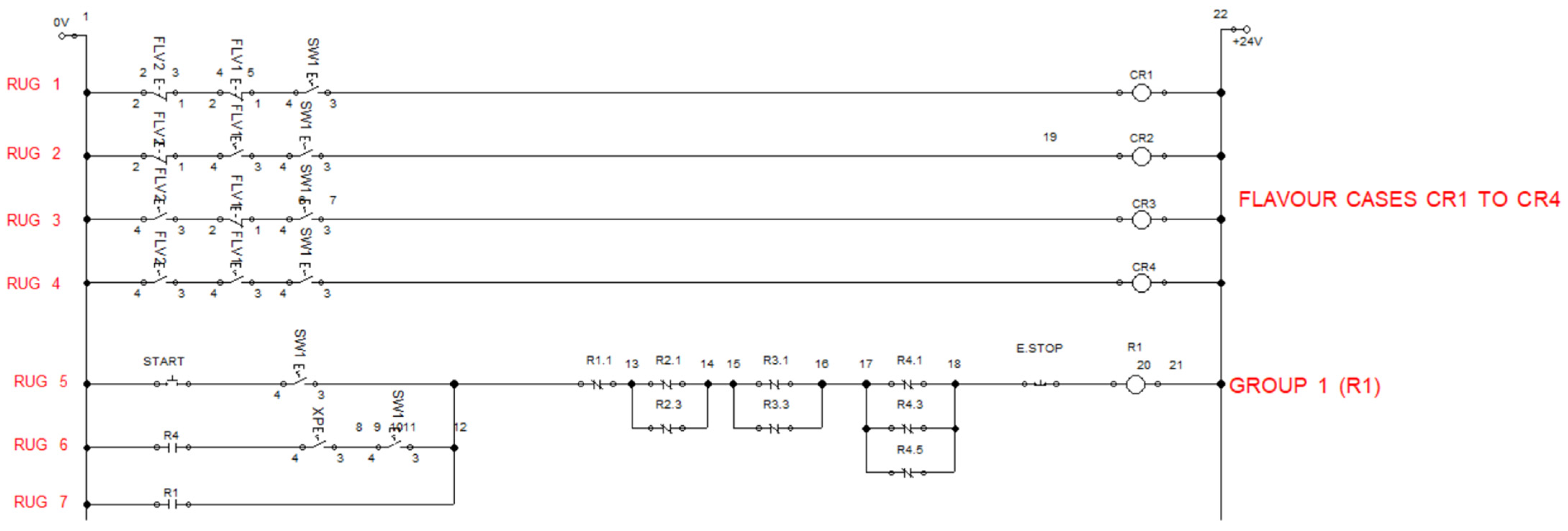
As a discrete event control system, the output of every rung in the ladder diagram can be described as a state variable, which is related to the status of one event switch having two possible values, “false” or “true.”. Here, a snapshot of the simulation model of ladder diagram is shown as follows (
Figure 8), which will be used to explain the machine sequence of the YFM.
Case 4 is chosen for presentation in the relay ladder where two flavors are selected with base yogurt when bottle is detected by proximity SW1 and enabled repeat cycle (XP = True). Therefore, three parallel paths (R4.1–R4.6) are enabled for plain yogurt and two flavors, 1 and 2.
4. Simulation Results Using FluidSIM
Festo simulator FluidSIM-MecLab software was used for computing and simulating the possible outcomes of the designed YFM. It was executed by rectifying all the syntax errors. The simulation results contributed an interactive mode so as to check its operation flow step by step. The interactive control mode of the machine program at every stage of filling and response of filled devices was highlighted. In this study, the output of the simulation is the relay ladder diagram that assists and reflects the RLL downloaded to the WAGO PFC. In this sense, the simulation model of the RLL and state diagram can be considered a validation tool for the YFM automation.
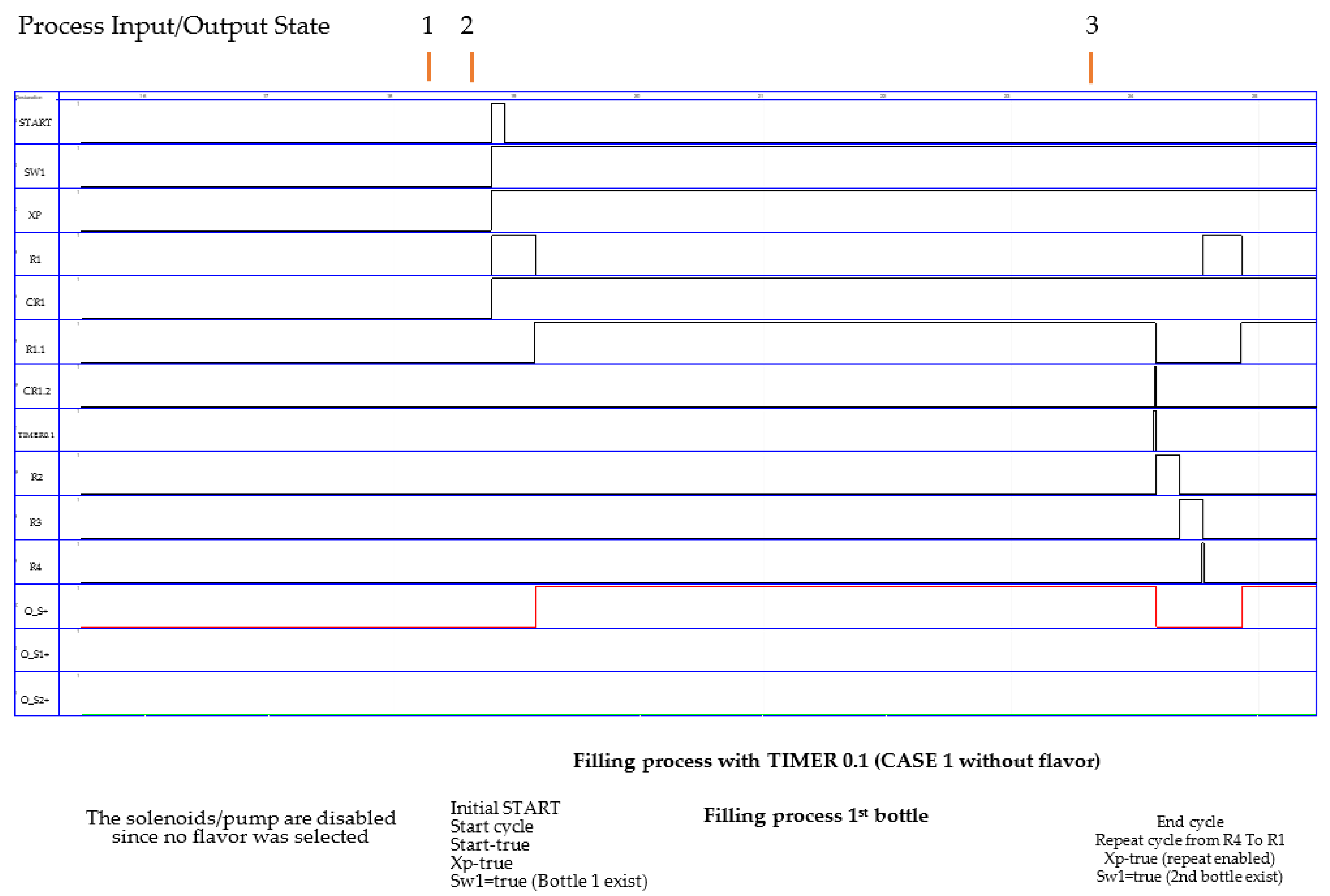
4.1. State Diagrams Results
As noted earlier, it is possible to obtain all four customer cases for the YFM (cf.
Section 3.3). For simplicity, we will present case one.
Table 3 shows the input/output variables for case one.
Figure 9 shows the state diagram for a machine sequence. All the process inputs and outputs are listed on the left-hand vertical axis. On the horizontal axis is the time interval during the run of the process. For instance, at time state (1), the process started when the START state changed to true when both SW1 and XP were also true. They are located in the first, second, and third rows from the top. In this event, too, the state case of yogurt filling CR1 becomes true; see the fifth row from the top of the state diagram. In this case, the result of plain yogurt filling (no flavors) is set and the corresponding CASCADE group G1.1 (i.e., R1.1) changes to the true state for 14.85 s. This corresponds to the assigned 14.85 s (timer 0.1) for bottle-feeding via pump/solenoid valve output (O+S+). Refer to the third row from the bottom of the state diagram. It covers the interval time events from two up to three; see the header row on the state diagram.
In other words, the YFM system will result in 242.4 bottles per hour, with no flavors requested assuming that the feeding-bottle system is filled with empty bottles.
4.2. Learning Factory Sequel Results
For a period of time, the production rate of the different flavors of yogurt was calculated based on the number of products ordered. Due to the event driven execution of the production line, different scenarios during product development were also considered. Consequently, the operation was halted in the next stage of product development when no new empty bottle was available in the bottle-feeding system or when a yogurt bottle went missing in the conveyor system. The production rate of filling the flavored yogurt bottles after adapting new techniques based on industry 4.0 was evaluated as shown in
Table 4.
The first advantage was the reduction in the time taken for bottle identification, and the second was due to the usage of the diaphragm pumps. The real-time operation of the YFM executed in three different modes of production (repetitive, discrete, and project IR4.0). The mass customization production line (LF) we had developed can deliver flavored yogurt bottles in different sequences based on the order of the NFC tags stacked. It is obvious that the pattern of flavor filling and its quantity can be altered in a short amount of time. The variations in the filling quantity differ completely from the preceding phase.
5. Discussion
In this second phase, the overall functionality and safety aspects have been improved. The rate of production in filling the flavored yogurt cans in different modes of production were evaluated (
Table 5). From the results, we interlink solutions for the small and medium-sized enterprises (SME) and micro, small and medium enterprises (MSME) who prefer developing a smart product with different modes of production in a single machine.
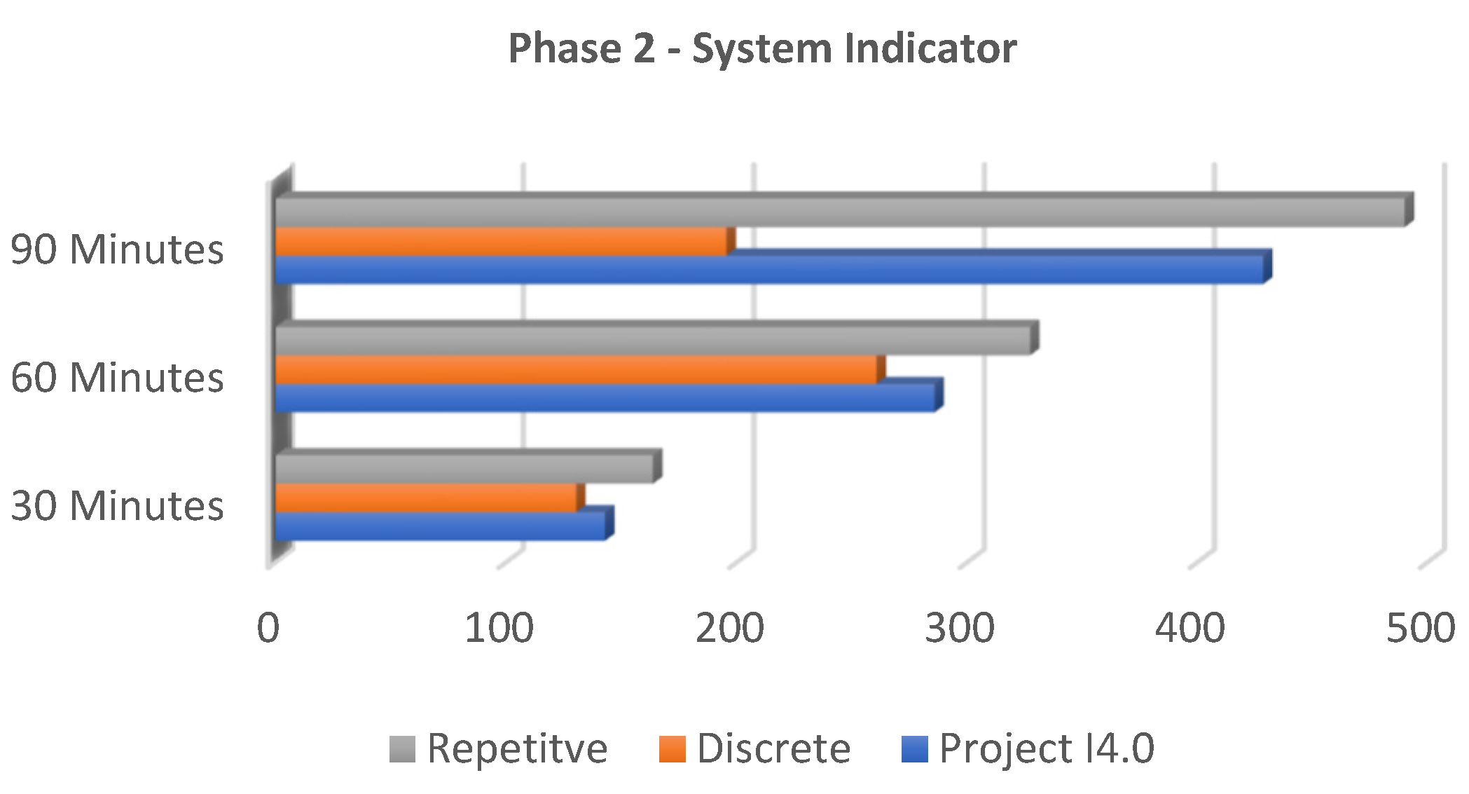
In a repetitive production mode, a single flavor with a single quantity delivered a greater number of products. After implementing the concepts of industry 4.0, a high difference in the quantity was observed compared to the discrete mode and repetitive mode. The production rate of project IR4.0 was in between the discrete and repetitive modes. In this phase, the polarity of the production rate was more aligned towards the repetitive mode. From the results, the improvements are evidently effective. The difference of the timing in filling one flavored yogurt bottle between the first phase and the second is precisely 15.88 s (
Figure 10), and the production rate spiked by 160.4 bottles per hour (
Table 6). Compared to the previous system, our production rate increased by 44.15%. One of the project’s main objectives was achieved, and the methodology we used to accomplish them was highly effective. Our initiative to develop a learning factory for our sustainable enhancement, yielding smart products by mass customization for the consumer, will be continued.
Redesigning the production process to increase the productivity and reduce the cycle time was focused on improving key performance indicators (KPI). Specifically, the comparison of the product development time and volume (or) mix flexibility between two phases of production was an important factor. Our team tabulated quantifiable measures to track product development over time. We optimized the production performance and evaluated its results compared to the previous phase (
Table 4). The proposed program algorithm (
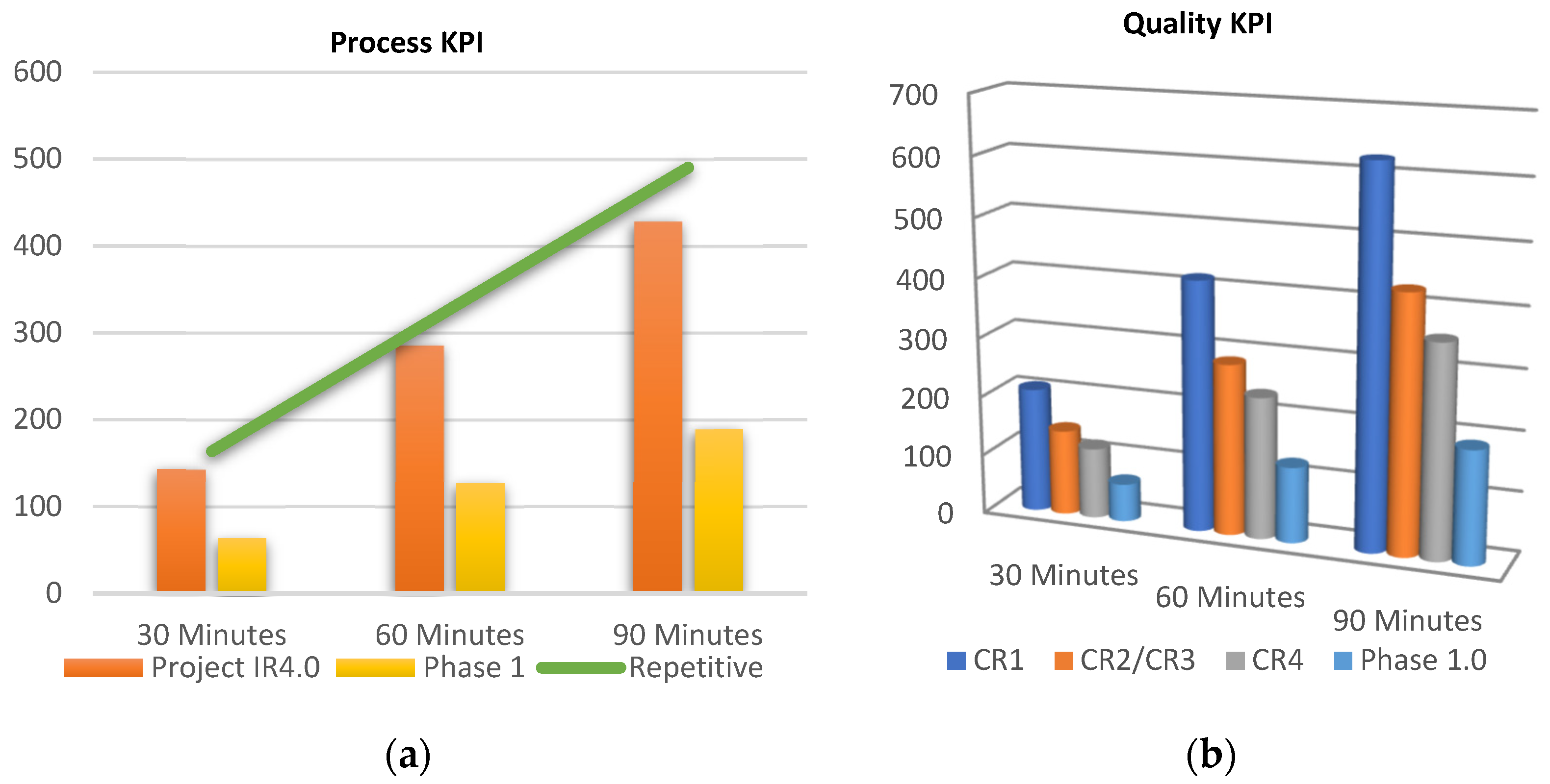
Figure 6) was strategized to shorten the production course (product development time). The flavored yogurt filling time and precision quantity filling, on evaluation, accorded to successful KPI objectives, such as advances in the detection of equipment availability (i.e., detection of empty yogurt cans stacked (w.r.t)) for the customer order. The customer lead time, machine productivity, equipment downtime, and overall equipment effectiveness (OEE) escalated as per the process KPI (
Figure 11a). The internal quality audit results (yogurt flavor mixing proportion), negligible defective products per thousand units, and NFC tag showcasing the product information (in our case, date and time of production) deepened the customer satisfaction and escalated the quality KPI (
Figure 11b). Moreover, factors such as the accuracy of the customer order fulfillment and dock to stock concept escalated the supply chain KPI.
Our goals for the servitization in order to develop a smart product, enhanced according to the customer’s needs by adapting robust concepts of industry 4.0 w.r.t second phase, were accomplished. The second phase consists of the pre-production stage indicators for proper material consumption to increase product variability; in our case, new cocktail yogurt CR4—FLAV 1 and FLAV2 (
Table 2), as well as a reduction in the time to deliver a finished product, and production stage indicators, such as a coefficient of total production and adherence to the production schedule with the number of completed products in a period of time, which are outlined (
Figure 11b).
Combined with the overall equipment effectiveness (OEE) for the output utilization, the time utilization and quality indicator increased the key performance indicator (KPI) (
Figure 11). It is evident that there is an increase in the production rate for the production mode IR4.0, and its production rate is much closer to the repetitive mode. This is an affirmation that machinery, when adapting concepts of industry 4.0 in order to develop a customized smart product, can achieve a production rate close to the repetitive mode. Therefore, the conventional misconceptions related to the high difference in the rate of production compared to project IR4.0 and the repetitive mode are diminished when the concept of industry 4.0 and the appropriate program paradigm were applied. In addition, the flexibility regarding the different flavor mix was eased in the second phase upon implementing the new sequence program. Irrespective of any flavor combination, the quantity of the yogurt bottle filling was always higher compared to phase 1.
6. Conclusions
The second phase of building our learning factory based on industry 4.0 was completed. After testing the YFM, the evaluated data were compared to the previous phase.
The accomplished objectives of integrating the industry 4.0 concept are:
Utilizing the additive manufacturing process (3D printer) to build mechanical parts for our YFM
Smart monitoring of production process via Internet and tracking product development at every stage
Smart control of production line to force stop or actuate field devices via Internet during production process
Advanced robotics, incorporating robotic arm performing multiple processes in parallel to production process
As a first step, new bilateral approach to upgrade the programming algorithm and modern hardware equipment to build a sustainable model for cognitive computing
Addition of NFC tag (RFID technologies) to upgrade as a smart product
Machine to machine (M2M) parallel interaction of three controllers to develop a single product (WAGO PFC, FANUC Controller and Raspberry Pi)
Simulation of ladder logic program using FESTO FluidSIM-MecLab software to verify operational sequence.
This prototype model highlighted the new emerging technologies that integrate the cyber-physical systems (field devices) with the industrial Internet of things (IIoT), near field communication (NFC) module, Raspberry Pi module, and robotic arm. Therefore, the system has been enhanced from multiple perspectives.
Our team, comprising industrial engineering graduates, department faculty members, and researchers, built a prototype that will educate, train, and motivate innovation. This research unites standalone student projects with an experiential learning process. It demonstrates a production line comprising multiple stations/controllers/operations that are reconfigurable and will include logistics (supply chain) until customer feedback. On building this YFM, we combined techniques to solve real-time issues and demonstrated practical projects as experimental learning for students. At every stage of development, we designed the system using CAM, SolidWorks, Auto CAD, Autodesk Inventor, or CATIA software available at our lab. Additionally, for the simulation of the designs and programs, we utilized the available FluidSIM-MecLab, Ansys, MATLAB, and Simulink software for verification. We facilitated the data accessing and data processing via the Internet. A physical product was manufactured (in our case—flavored yogurt) by an educational concept that comprises formal, informal, and non-formal learning methods. By building a reconfigurable production line built to resemble a real value chain, we intend to educate engineering graduates about the upcoming techniques and equipment/recent trends in manufacturing that are future-oriented and not included as much in the traditional curriculum pattern as of now.
An innovative control architecture, utilizing the concepts of industry 4.0 and the NFC platform to improve customer satisfaction, was proposed and implemented in this paper using FluidSIM-MecLab. The simulation with FluidSIM-MecLab saved programming time, errors, and test trials before transferring the program to the PFC. In the next phase, we intend to include wireless IOT sensors to facilitate the smart product movement along the production line. A live shop floor KPI visualization board is to be included in an upcoming phase to evaluate the product development time. Moreover, we look forward to adding an end user requirement/customized demand to drive the process execution of our developing YFM via the Internet by integrating the appropriate platforms, such as NODE RED and MQTT. In a short span, we foresee the inclusion of social media applications that will enable consumers to choose the expected flavor and quantity and eliminate any halt for scanning during production. Our developing YFM conveyed an optimal solution by reducing the operation cost, increasing the production rate, and filling precise quantities. Such smart products will encourage the stakeholders in the SME and MSME category to confidently incorporate industry 4.0 concepts. This new paradigm will promote digitalization in the production process to attain the goals of “Vision 2030”, a Kingdom of Saudi Arabia initiative for industrial development. Thus, the upcoming SMEs and MSMEs in our region will excel by transforming the production techniques to develop smart and sustainable products for our better future.
Author Contributions
Conceptualization, B.S. and S.K.; methodology, B.S. and A.M.A.; software S.K., B.S. and A.M.A.; validation, B.S. and A.M.A.; formal analysis, B.S., S.K. and A.M.A.; investigation, S.K.; resources, B.S.; data curation, B.S.; writing—original draft preparation, B.S., A.M.A. and S.K.; writing—review and editing, M.R.; visualization, B.S.; supervision, B.S.; project administration, B.S.; funding acquisition, B.S. All authors have read and agreed to the published version of the manuscript.
Funding
This study received funding from King Saud University, Saudi Arabia through researchers supporting project number (RSP-2021/145). Additionally, the APCs were funded by King Saud University, Saudi Arabia through researchers supporting project number (RSP-2021/145).
Institutional Review Board Statement
Not applicable.
Informed Consent Statement
Not applicable.
Data Availability Statement
Not applicable.
Conflicts of Interest
The authors declare no conflict of interest.
References
- Zawadzki, P.; Żywicki, K. Smart product design and production control for effective mass customization in the Industry 4.0 concept. Manag. Prod. Eng. Review. 2016, 7, 105–112. [Google Scholar] [CrossRef]
- Mian, S.H.; Salah, B.; Ameen, W.; Moiduddin, K.; Alkhalefah, H. Adapting Universities for Sustainability Education in Industry 4.0: Channel of Challenges and Opportunities. Sustainability 2020, 12, 6100. [Google Scholar] [CrossRef]
- Shrouf, F.; Ordieres, J.; Miragliotta, G. Smart factories in Industry 4.0: A review of the concept and of energy management approached in production based on the Internet of Things paradigm. In Proceedings of the 2014 IEEE International Conference on Industrial Engineering and Engineering Management, Selangor Darul Ehsan, Malaysia, 9–12 December 2014; pp. 697–701. [Google Scholar]
- Calegari, L.P.; Avalone, M.C.; Fettermann, D.C. Barriers and enablers to food mass customization. J. Agribus. Dev. Emerg. Econ. 2020, 10, 403–428. [Google Scholar] [CrossRef]
- Kortuem, G.; Kawsar, F. Market-based user innovation in the internet of things. In Proceedings of the 2010 Internet Things, Tokyo, Japan, 30 December 2010. [Google Scholar] [CrossRef] [Green Version]
- Kamble, S.S.; Gunasekaran, A.; Ghadge, A.; Raut, R. A performance measurement system for Industry 4.0 enabled smart manufacturing system in SMMEs- A review and empirical investigation. Int. J. Prod. Econ. 2020, 229, 107853. [Google Scholar] [CrossRef]
- Oluyisola, O.E.; Bhalla, S.; Sgarbossa, F.; Strandhagen, J.O. Designing and developing smart production planning and control systems in the Industry 4.0 era: A methodology and case study. J. Intell. Manuf. 2021. [Google Scholar] [CrossRef]
- Buer, S.-V.; Strandhagen, J.O.; Chan, F.T.S. The link between Industry 4.0 and lean manufacturing: Mapping current research and establishing a research agenda. Int. J. Prod. Res. 2018, 56, 2924–2940. [Google Scholar] [CrossRef] [Green Version]
- Salah, B.; Khan, S.; Ramadan, M.; Gjeldum, N. Integrating the Concept of Industry 4.0 by Teaching Methodology in Industrial Engineering Curriculum. Processes 2020, 8, 1007. [Google Scholar] [CrossRef]
- Orcioni, S.; Pellegrini, R.; Seepold, R.; Gaiduk, M.; Madrid, N.M.; Conti, M. Medication adherence supported by mHealth and NFC. Inform. Med. Unlocked 2021, 23, 100552. [Google Scholar] [CrossRef]
- Salah, B.; Khan, S.; Gjeldum, N. An automatic yogurt filling system built from scratch based on Industry 4.0 concept. Trans. FAMENA 2020, 44, 59–70. [Google Scholar] [CrossRef]
- WAGO Kontakttechnik GmbH & Co. KG. “e!COCKPIT Application Note e!Cockpit”, Germany. 2019. Available online: https://www.wago.com/global/ (accessed on 1 October 2021).
Figure 1.
Electrical control panel and its related components.
Figure 1.
Electrical control panel and its related components.
Figure 2.
Head nozzle in the yogurt filling station.
Figure 2.
Head nozzle in the yogurt filling station.
Figure 3.
Transferring empty bottles with a Fanuc robot.
Figure 3.
Transferring empty bottles with a Fanuc robot.
Figure 4.
(a) Yogurt bottles were equipped with a color code, where (b) yogurt bottles are equipped with NFC tags.
Figure 4.
(a) Yogurt bottles were equipped with a color code, where (b) yogurt bottles are equipped with NFC tags.
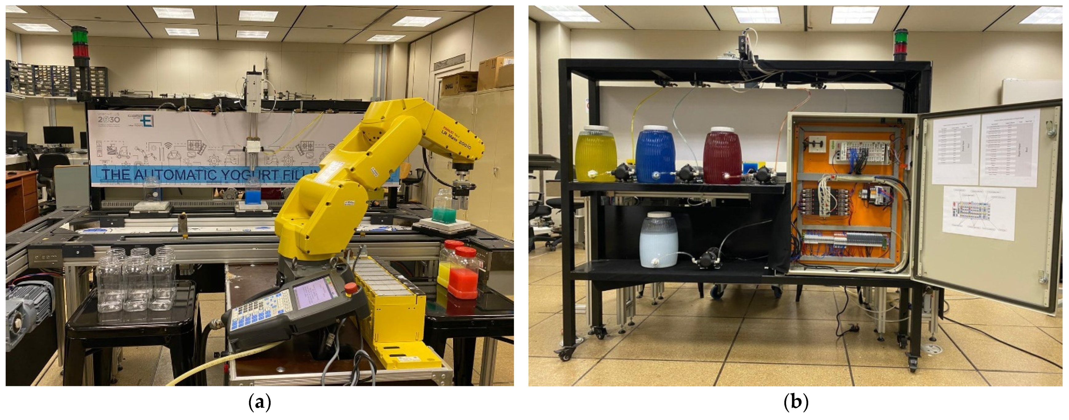
Figure 5.
Designed smart yogurt filling machine and implementation: (a) main components of the proposed system at the front side, including robotic arm, conveyor belt, solenoid valves nozzle with three heads, proximity sensors, and cup/filling pneumatic actuators; (b) main components of the proposed system at the back side, including filling containers (plain yogurt and flavored), and electrical control panel with WAGO PFC controller.
Figure 6.
Sequencing of machining operations.
Figure 6.
Sequencing of machining operations.
Figure 7.
The pneumatic network for cylinders X and Y.
Figure 7.
The pneumatic network for cylinders X and Y.
Figure 8.
A Snapshot of the simulation model using FluidSIM-MecLab case 4.
Figure 8.
A Snapshot of the simulation model using FluidSIM-MecLab case 4.
Figure 9.
State diagram of the YFM in FluidSIM-MecLab.
Figure 9.
State diagram of the YFM in FluidSIM-MecLab.
Figure 10.
Phase-2 system indicator.
Figure 10.
Phase-2 system indicator.
Figure 11.
Key performance indicators: (a) process KPI increment in production rate vs. reduction in product development time; (b) quality KPI related to flavor mix flexibility in new program algorithm vs. phase 1.
Figure 11.
Key performance indicators: (a) process KPI increment in production rate vs. reduction in product development time; (b) quality KPI related to flavor mix flexibility in new program algorithm vs. phase 1.
Table 1.
Default values of timer intervals (plain yogurt (BY) and three flavor pumps) for three-bottle volume.
Table 1.
Default values of timer intervals (plain yogurt (BY) and three flavor pumps) for three-bottle volume.
| Bottle Vol. (mL) | BY. TMR (s) | FLV1. TMR (s) | FLV2. TMR (s) |
|---|
| 100 | 7 | 3.5 | 3.5 |
| 300 | 14.85 | 7.65 | 7.65 |
| 500 | 22.8 | 10.8 | 10.8 |
Table 2.
Default values of timer intervals for three-bottle volumes.
Table 2.
Default values of timer intervals for three-bottle volumes.
| | Case | FLV2 | FLV1 | B | CR# |
|---|
| Pure plain yogurt | 1 | 0 | 0 | 1 | CR1 |
| | | 0 | 1 | 0 | |
| Plain yogurt with flavor 1 | 2 | 0 | 1 | 1 | CR2 |
| | | 1 | 0 | 0 | |
| Plain yogurt with flavor 2 | 3 | 1 | 0 | 1 | CR3 |
| | | 1 | 1 | 0 | |
| Plain yogurt with flavor 1 and 2 | 4 | 1 | 1 | 1 | CR4 |
Table 3.
Program input/output variables.
Table 3.
Program input/output variables.
| Variable | Description |
|---|
| START button | The cycle starts when it is pressed |
| Selector switch xp | Enable the decision to repeat the cycle |
| proximity detector SW1 | Detecting the presence of an empty bottle |
| CASCADE’s main group | The machine cycle is divided into main groups (G1, G2, G3, and G4) |
| CASCADE’s subgroups | Subgroubs (G1.1 and G1.2 for case 1or CR1), (G4.1, G4.3, … G4.6 for case 4 or CR4). |
| O_S+ | The SOLINOID/Diaghram pump valve is opened to allow the Plain yogurt to pass through |
| O_S1+ | The SOLINOID/Diaghram pump valve is opened to allow the Flavor1 to pass through |
| O_S1+ | The SOLINOID/Diaghram pump valve is opened to allow the Flavor2 to pass through |
Table 4.
Production rate comparison chart.
Table 4.
Production rate comparison chart.
| Research Stage | Scanning Tool | Scanning Time (s) | Type of Liquid Flow Pressure | 300 mL Yogurt Can Filling Time (s) | Total Time Taken [Per Bottle] (s) |
|---|
| Phase 1 | Color Sensor | 6 | Gravitational force | Base yogurt | Flavored topping | 28.5 |
| 14.85 | 7.65 |
| Phase 2 | NFC tag reader | 4 | Diaphragm pumps | Unified Liquid flow nozzle | 12.62 |
| 8.62 |
Table 5.
Production rate in different modes.
Table 5.
Production rate in different modes.
| Time Taken | Project I4.0 | Discrete | Repetitive |
|---|
| 30 min | 142.8 | 130.24 | 163.6 |
| 60 min | 285.7 | 260.49 | 327.2 |
| 90 min | 428.5 | 195.36 | 490 |
Table 6.
Performance indicators for different production modes.
Table 6.
Performance indicators for different production modes.
| | Project I4.0 | Phase 1 (60 min) | Repetitive | Discrete |
|---|
| 30 min | 142.8 | 63.15 | 163.6 | 130.24 |
| 60 min | 285.7 | 126.31 | 327.2 | 195.36 |
| 90 min | 428.5 | 189.47 | 490 | 260.49 |
| Publisher’s Note: MDPI stays neutral with regard to jurisdictional claims in published maps and institutional affiliations. |
© 2021 by the authors. Licensee MDPI, Basel, Switzerland. This article is an open access article distributed under the terms and conditions of the Creative Commons Attribution (CC BY) license (https://creativecommons.org/licenses/by/4.0/).


