
Modular Segmented Motor for Power-Assist Wheelchairs: Proof of Concept


Abstract
:1. Introduction
1.1. Characterisation of Wheelchair Users
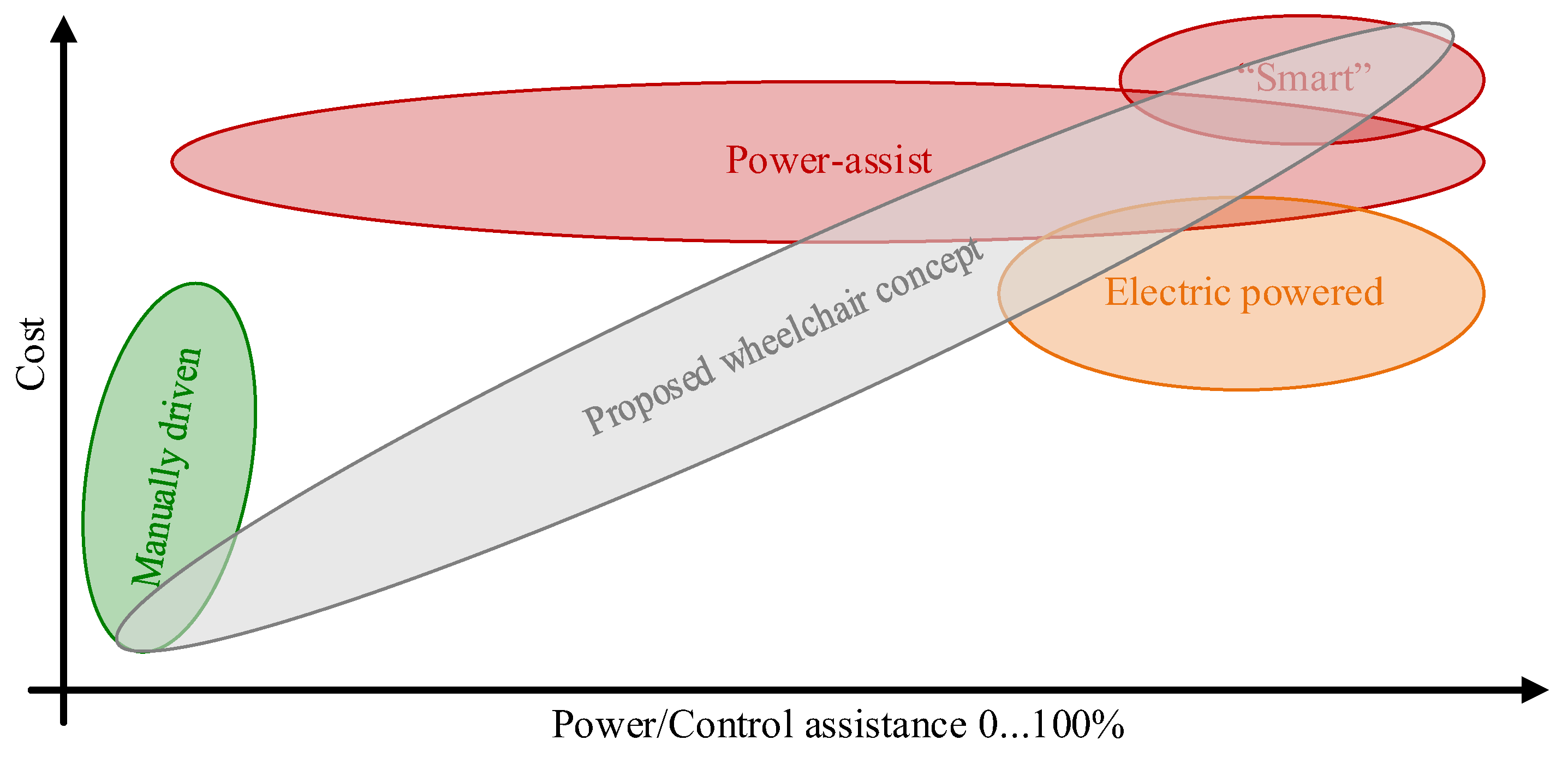
1.2. Overview of Wheelchair Types, Present on Market
- Variable levels of assisting, meaning that some wheelchair users require full-motion power from their wheelchair (full assistance), while other users, who are able to move the wheelchair with their own muscular power, require only some additional power for ease of movement or in difficult places.
- In the case of full assistance, wheelchair control is achieved by the joystick method, etc. In the case of partial assistance, wheelchair control is provided, to a greater or lesser extent, by the muscular strength of the user. Some kind of torque sensing and amplification is required that is obviously easier to do in an electrical machine.
- The upper mass limit of the user of the designed wheelchair is defined as 120 kg. With this mass, the wheelchair electric drive system works most efficiently. However, the vast majority of wheelchair users do not achieve this mass limit. Therefore, it is necessary to make the wheelchair as efficient as possible for masses under 120 kg.
1.3. Modifying Power Drive Train for Better Cost Availability
2. Motor Requirements for Electric-Powered and Power-Assist Wheelchairs
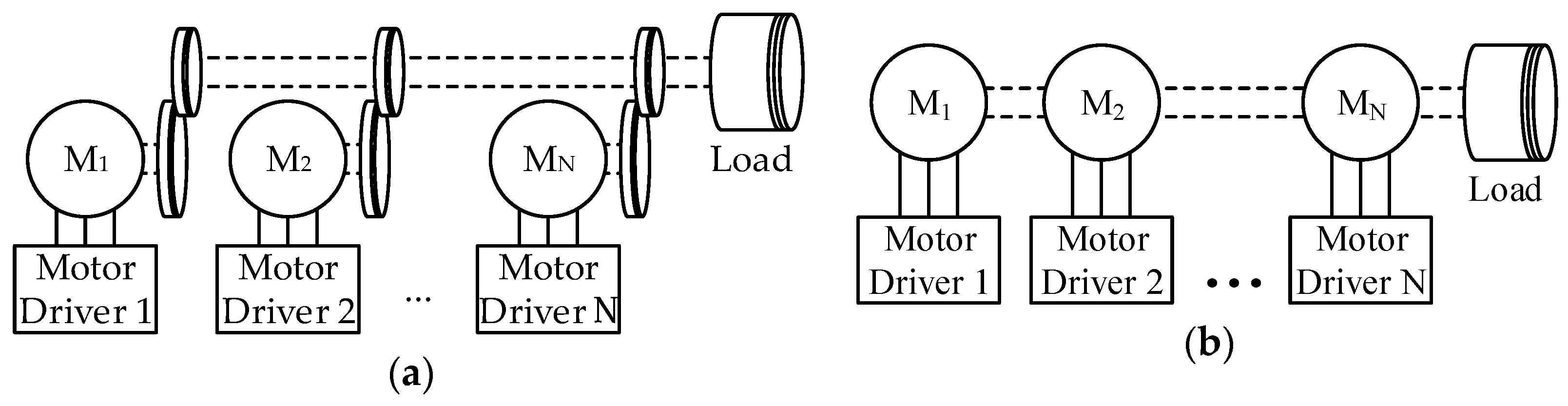
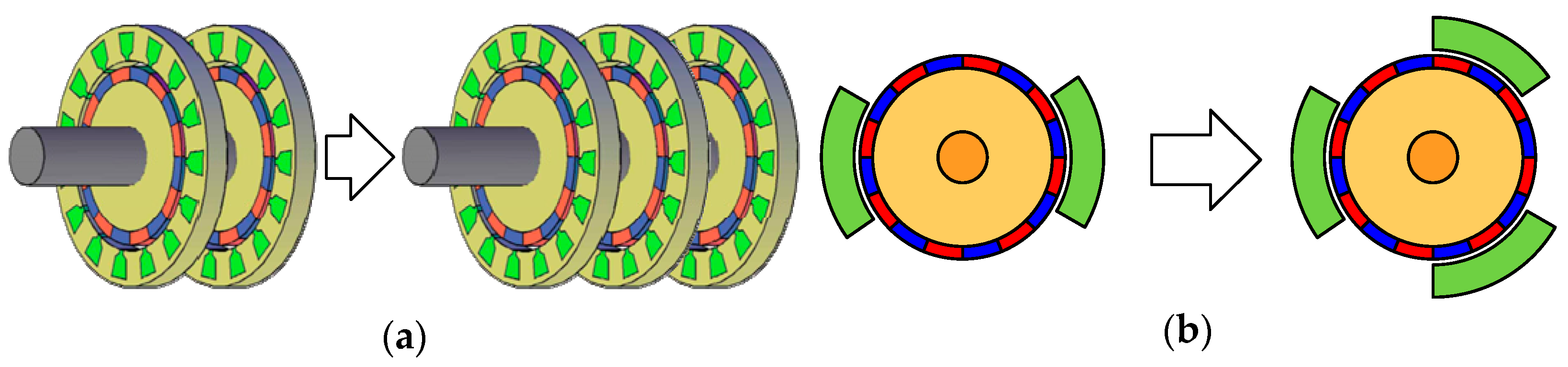
3. Concept of Segmented Modular PMSM
3.1. Generalized Description of Concept
3.2. Calculation of Main Parameters of Armature Slots
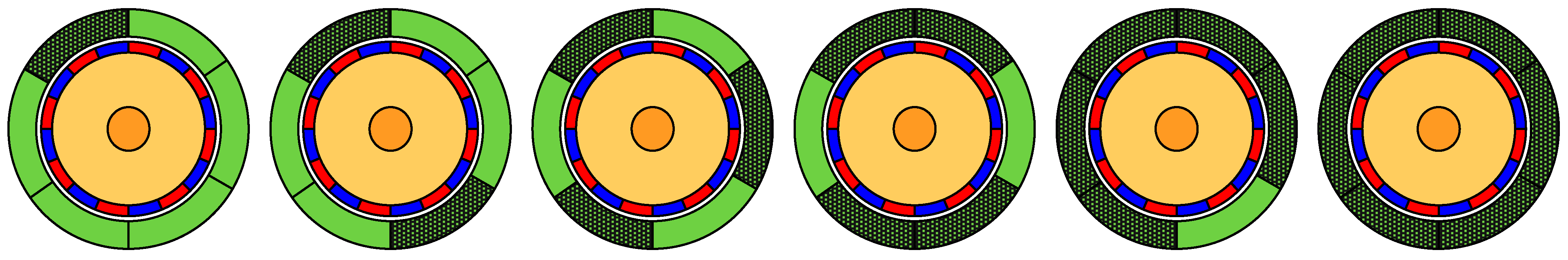
4. Arrangement of Basic Motor Elements and Prototype Layout
5. Evaluation of Parameters of Segmented PMSM
5.1. Magnetic Parameters
5.2. Electrical Parameters
5.2.1. Stator Phase Resistance Rs
5.2.2. Stator Phase Inductances Ld and Lq
5.3. Mechanical Parameters and Power
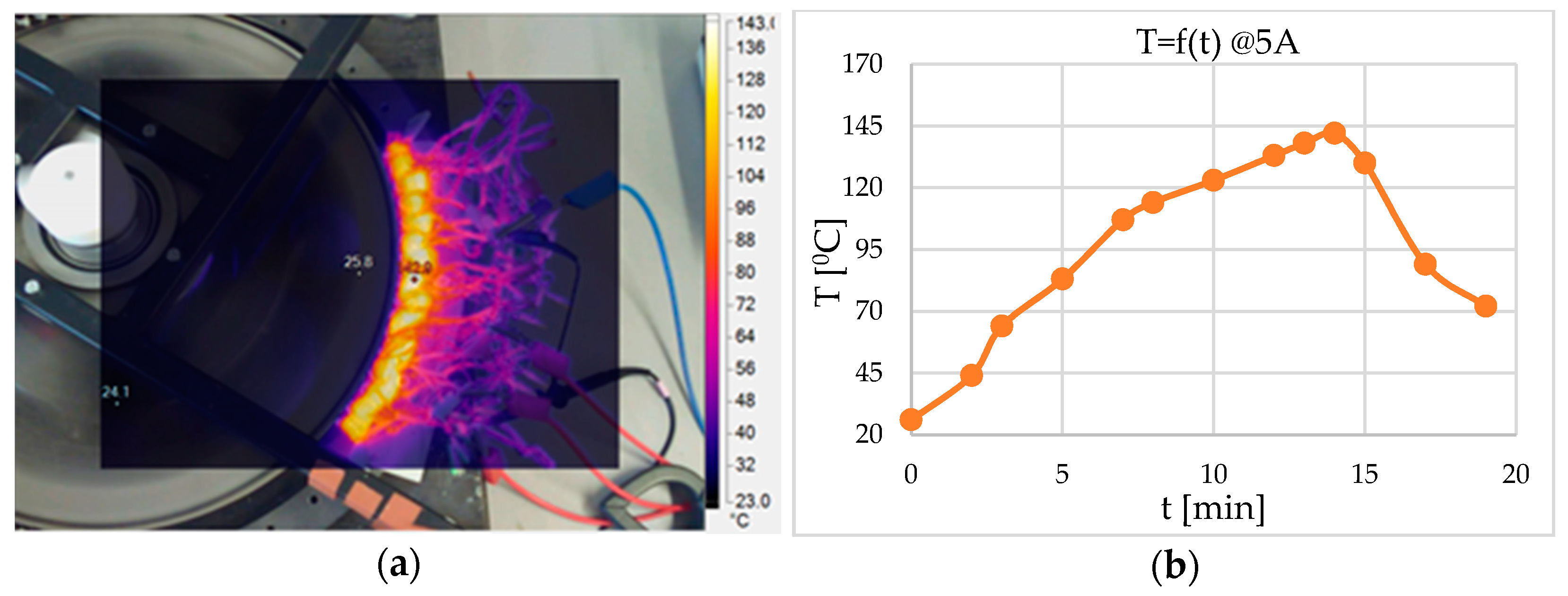
5.4. Thermal Considerations
6. Discussion and Conclusions
- (1)
- It is necessary to develop the design methodology for modular segmented motors, to bring forward parameter calculation procedures, and to clarify the design fitting to particular applications.
- (2)
- It is also important to improve the energy efficiency of the motor (the achieved one is 75%, that is not much, even for low power motors). First of all, the efficiency of the motor, composed of three, four, five, and six segments, has to be evaluated while the motor losses have to be allocated. Then, the proposals for efficiency improvement have to be brought forward.
- (3)
- As was concluded in Section 5.4, this particular motor also has cooling problems. Even at higher energy efficiency, the power losses of the motor (5 … 10% of 300 W, which is 15 … 30 W)) in closed operation environments may lead to significant overheating. At the same time, the obviously distant location of the segments and cooling elements requires the use of a sophisticated cooling system, for example, a loop heat pipe with an elastic connection between the evaporator and the condenser. This work is another potential extension of this research.
- (4)
- At last, it is necessary to develop the power electronic driver and its control unit for the motor and the drive, as well as to study the obtained segmented drive on the whole.
Author Contributions
Funding
Institutional Review Board Statement
Informed Consent Statement
Data Availability Statement
Conflicts of Interest
References
- European Commission. A Clean Planet for all. A European long-term strategic vision for a prosperous, modern, competitive and climate neutral economy. Com 2018, 773, 114. [Google Scholar]
- Delhi, S.I.N. Automotive Revolution & Perspective towards 2030. Auto Tech. Rev. 2016, 4, 20–25. [Google Scholar]
- Sarlioglu, B.; Morris, C.T.; Han, D.; Li, S. Driving Toward Accessibility: A Review of Technological Improvements for Electric Machines, Power Electronics, and Batteries for Electric and Hybrid Vehicles. IEEE Ind. Appl. Mag. 2017, 23, 14–25. [Google Scholar] [CrossRef]
- Rastogi, S.K.; Sankar, A.; Manglik, K.; Mishra, S.K.; Mohanty, S.P. Toward the Vision of All-Electric Vehicles in a Decade [Energy and Security]. IEEE Consum. Electron. Mag. 2019, 8, 103–107. [Google Scholar] [CrossRef]
- Bertoluzzo, M.; Buja, G. Development of electric propulsion systems for light electric vehicles. IEEE Trans. Ind. Inform. 2011, 7, 428–435. [Google Scholar] [CrossRef]
- Electric Vehicle Database, Hyundai Kona Electric. Available online: https://ev-database.org/car/1239/Hyundai-Kona-Electric-39-kWh (accessed on 5 October 2021).
- Galkin, I.; Podgornovs, A.; Blinov, A.; Vitols, K.; Vorobyov, M.; Kosenko, R. Considerations regarding the concept of cost-effective power-assist wheelchair subsystems. Electr. Control Commun. Eng. 2018, 14, 71–80. [Google Scholar] [CrossRef] [Green Version]
- Galkin, I.; Blinov, A.; Verbytskyi, I.; Zinchenko, D. Modular self-balancing battery charger concept for cost-effective power-assist wheelchairs. Energies 2019, 12, 1526. [Google Scholar] [CrossRef] [Green Version]
- World Report on Disability 2011; World Health Organization: Geneva, Switzerland, 2011; pp. 1–350.
- Kraus, L.; Lauer, E.; Coleman, R.; Houtenville, A. 2017 Disability Statistics Annual Report: A Publication of the Rehabilitation Research and Training Center on Disability Statistics and Demographic; Univ. NH New Hampshire: Durham, NH, USA, 2018. [Google Scholar]
- Disability Statistics. Eurostat Statistics Explained. 2019. Available online: https://ec.europa.eu/eurostat/statistics-explained/index.php/Disability_statistics (accessed on 21 August 2019).
- Dudgeon, B.J.; Deitz, J.C.; Dimpfel, M. Wheelchair Selection. In Occupational Therapy for Physical Dysfunction; Wolters Kluwer Health/Lippincott Williamns & Wilkins: Philadelphia, PA, USA, 2013. [Google Scholar]
- Ding, D.; Cooper, R.A. Electric-Powered Wheelchairs. IEEE Control Syst. Mag. 2005, 25, 22–34. [Google Scholar]
- Hou, R.; Shi, X.; Krishnamurthy, M. Design and implementation of a novel power assisted drivetrain for a wheelchair. In Proceedings of the 2012 IEEE Transportation Electrification Conference and Expo (ITEC), Dearborn, MI, USA, 18–20 June 2012; pp. 1–6. [Google Scholar]
- Yang, Y.-P.; Lin, H.-C.; Tsai, F.-C.; Lu, C.-T.; Tu, K.-H. Design and integration of dual power wheels with rim motors for a powered wheelchair. IET Electr. Power Appl. 2012, 6, 419. [Google Scholar] [CrossRef]
- Jajtic, Z.; Ulmar, E.; Volmert, C.; Fretzscner, S.; Pommer, H.; Dorfner, M. Segmented electric machine—Modular motor and system topology for direct drives. In Proceedings of the 2011 1st International Electric Drives Production Conference, Nuremberg, Germany, 28–29 September 2011; pp. 36–39. [Google Scholar]
- Salminen, P.; Niemelä, M.; Pyrhönen, J. Performance analysis of fractional slot wound PM-motors for low speed applications. In Proceedings of the Conference Record of the 2004 IEEE Industry Applications Conference, Seattle, WA, USA, 3–7 October 2004. [Google Scholar] [CrossRef]
- Salminen, P. Fractional Slot Permanent Magnet Synchronous Motors for Low Speed Applications. Ph.D. Thesis, Lappeenranta University of Technology, Lappeenranta, Finland, 20 December 2004. [Google Scholar]
- Lifanov, V.A. Calculation of Low-Power Electric Machines with Excitation from Permanent Magnets: A Tutorial; Chelyabinsk Publishing Center: Chelyabinsk, Russia, 2010; p. 164. (In Russian) [Google Scholar]
- Hanselman, D. Brushless Permanent Magnet Motor Design; Magna Physics Publishing: Lebanon, OH, USA, 2006. [Google Scholar]
- Meier, S. Theoretical Design of Surface-Mounted Permanent Magnet Motors with Field-Weakening Capability. Master’s Thesis, Royal Institute of Technology, Stockholm, Sweden, 2002. [Google Scholar]
- Bianchi, N.; Bolognani, S. Design techniques for reducing the cogging torque in surface-mounted PM motors. IEEE Trans. Ind. Appl. 2002, 38, 1259–1265. [Google Scholar] [CrossRef]
- Fei, W.; Zhu, Z.Q. Comparison of cogging torque reduction in permanent magnet Brushless machines by conventional and herringbone skewing techniques. IEEE Trans. Energy Convers. 2013, 28, 664–674. [Google Scholar] [CrossRef]
- Lukaniszyn, M.; JagieLa, M.; Wrobel, R. Optimization of permanent magnet shape for minimum cogging torque using a genetic algorithm. IEEE Trans. Magn. 2004, 40, 1228–1231. [Google Scholar] [CrossRef]
- Liu, T.; Huang, S.; Gao, J.; Lu, K. Cogging torque reduction by slot-opening shift for permanent magnet machines. IEEE Trans. Magn. 2013, 49, 4028–4031. [Google Scholar] [CrossRef]
- Dosiek, L.; Pillay, P. Cogging torque reduction in permanent magnet machines. IEEE Trans. Ind. Appl. 2007, 43, 1565–1571. [Google Scholar] [CrossRef] [Green Version]


| Symbol | Quantity | Source | Value |
|---|---|---|---|
| v | Cruise speed (>70%) | ISO07176 | 5 km/h = 1.4 m/s |
| vmax | Maximal speed | ISO07176 | 15 km/h = 4.2 m/s |
| m | Full mass of the wheelchair and its user | Design parameter | 120 kg |
| f | Coefficient of rolling resistance (rubber-concrete) | Design parameter | 15 … 35 mm |
| Dwh | Wheel diameter | Design parameter | 660.4 mm |
| Coil | Phase A | Phase B | Phase C | |||
|---|---|---|---|---|---|---|
| In | Out | In | Out | In | Out | |
| 1 | 4 | 5 | 2 | 3 | 01 | 1 |
| 2 | 6 | 7 | 5 | 6 | 1 | 2 |
| 3 | 9 | 10 | 7 | 8 | 3 | 4 |
| 4 | 12 | 13 | 10 | 11 | 8 | 9 |
| 5 | 14 | 15 | 13 | 14 | 11 | 12 |
| Motor | Segment | |
|---|---|---|
| Ns | 90 | 15 |
| Nm | 72 | 12 |
| Nspp | 0.42 | 0.42 |
| ask, | 0.25 | 0.25 |
| ncog | 5 | 5 |
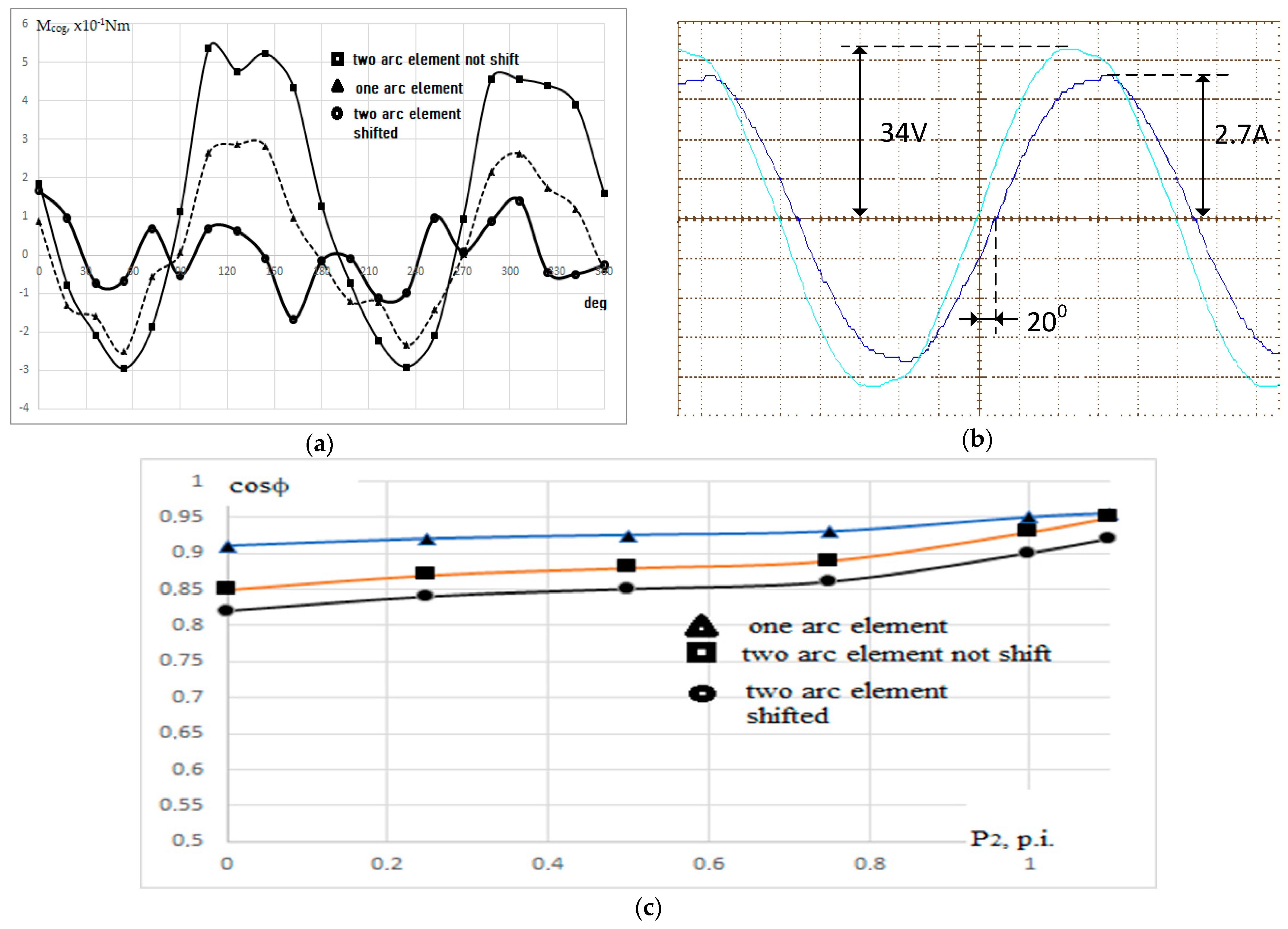
| Segments | Mload [Nm] | I [A] | cos ϕ | η | Psegm [W] |
|---|---|---|---|---|---|
| 1 | 3.9 | 1.9 | 0.95 | 0.75 | 57 |
| 2 (no shift) | 8.1 | 4.3 | 0.94 | 0.71 | 117 |
| 2 (shifted) | 8.2 | 4.2 | 0.92 | 0.74 | 119 |
Publisher’s Note: MDPI stays neutral with regard to jurisdictional claims in published maps and institutional affiliations. |
© 2021 by the authors. Licensee MDPI, Basel, Switzerland. This article is an open access article distributed under the terms and conditions of the Creative Commons Attribution (CC BY) license (https://creativecommons.org/licenses/by/4.0/).
Share and Cite
Galkin, I.A.; Geidarovs, R.; Podgornovs, A. Modular Segmented Motor for Power-Assist Wheelchairs: Proof of Concept. Machines 2021, 9, 227. https://doi.org/10.3390/machines9100227
Galkin IA, Geidarovs R, Podgornovs A. Modular Segmented Motor for Power-Assist Wheelchairs: Proof of Concept. Machines. 2021; 9(10):227. https://doi.org/10.3390/machines9100227
Chicago/Turabian StyleGalkin, Ilya A., Rahims Geidarovs, and Andrejs Podgornovs. 2021. "Modular Segmented Motor for Power-Assist Wheelchairs: Proof of Concept" Machines 9, no. 10: 227. https://doi.org/10.3390/machines9100227