1. Introduction
Various nonlinear electrical power components, including switched-mode power supply, electrical ballast, and variable-frequency drive, are finding increasingly broad application in low-voltage distribution networks. The nonlinearity of the ensuring power conversion thus causes power quality problems, such as harmonic currents, harmonic voltages, low power factors, and unbalanced voltages, etc. [
1,
2].
Considering the economic efficiency, passive filtering techniques are widely used to improve power quality [
3]. Nevertheless, passive filters can only filter out specified harmonics, and the filtering performance is susceptible to system impedance [
4]. When the distribution network is of a low impedance regarding the passive filters, parallel resonance will easily occur between the distribution network and the filter. Unlike the passive filters, active filters can prevent the parallel resonance since the high-impedance current source has no influence upon the system impedance [
5,
6,
7,
8]. In practice, we can combine active and passive filters together as a hybrid one [
9]. Whatever the filtering technique is, it has broad applications mainly in transmission systems. Taking a converter transformer in DC networks as an example, it is difficult to install the filters or reactive compensation devices on the secondary (load) side of the transformer due to the large AC phase current of the conversion device (e.g., a harmonic source or reactive absorption device). Therefore, the compensation device is usually installed on the AC side of the converter transformer, which makes all harmonic currents and reactive power flow freely from the converter bridge through the transformer windings. These harmonic currents and power may lead to transformer loss, temperature rise, noise, and other issues [
10,
11]. Hence, manufacturers usually increase the transformer capacity to mitigate the adverse effects of “unrestricted” harmonic currents and reactive power. Nevertheless, the cost increase outweighs the mitigation performance, and the enhanced capacity cannot solve the problem completely.
In recent years, inductive filtering technology, a remedy for harmonic currents and reactive power compensation, has been developed to further curb the “unrestricted” components in converter transformers [
12,
13]. The inductive filter can restrict the “free” circulation of harmonic currents and reactive power, thus reducing their adverse effects on the converter transformer [
14,
15,
16]. Through a zero-value impedance winding design and connection of a fully tuned filtering device, the inductive filter can achieve the electromagnetic balance between the load and filter winding [
17,
18]. Overall, the inductive filter can inhibit harmonics and prevent them from flowing through the transformer’s winding connected to distribution systems. It can thus reduce the harmonics’ adverse impact on transformers [
19].
In practice, the fully tuned filtering branch in inductive filtering methods is usually composed of passive filtering devices. Although these passive filtering branches do not require tuning, they often fail to achieve full resonance due to design errors, aging of materials, and other factors. Limited by the manufacturing process, even if the filtering branch is perfectly tuned, the equivalent impedance of the filtering branch is present in the form of non-zero resistance [
20]. Furthermore, passive filter-based inductive filtering methods can only filter out the specified secondary harmonics of the corresponding filtering branch. The design of this filtering system is usually achieved by harmonic analysis of specific nonlinear loads. If the load changes frequently or the harmonic characteristics of the loads are unknown, the filtering system’s performance will deteriorate.
In order to further tap the potential of inductive filtering methods to improve power quality in distribution networks, researchers have designed hybrid inductive and active filters (HIAF). With the aid of both the filter and superconducting circuits of the inductive filtering transformer, an HIAF can offset the harmonics’ magnetic flux in the secondary winding. The harmonics are thus segregated in the low-voltage side of the transformer. Moreover, the active filter can further enhance the filtration performance. By analyzing the feasibility of the HIAF system in high-voltage direct-current (HVDC) systems, a voltage source inductive filtering converter was designed for the HVDC system [
21]. Some research studies use the HIAF system to improve the utility grid’s power quality. In its primary topological structure, the transformer adopts the extended and delta winding connection [
22]. The Ydd transformers and HIAF system are also used in wind power generation systems. The simulation and experimental results show that the HIAF system can effectively compensate for the reactive power and attenuate harmonics [
23]. An impedance matching-based HIAF system, containing an Ydy inductive filtering transformer, LCL filters, and voltage source convertor (VSC), has been proposed in [
24]. The designed HIAF system has both good steady-state and dynamic performance.
In this paper, we use an HIAF system to solve the power quality problem in low-voltage distribution systems. In the low-voltage networks, the transformer usually adopts the Dyn connection mode. The three-phase loads are probably unbalanced and there exists the 3rd harmonic caused by load nonlinearities. Therefore, we use the HIAF system to improve the power quality of distribution systems by filtering out these undesired harmonics. Specifically, we design a filtering system in which the core component is an inductive filter transformer. The proposed filtering system can effectively alleviate the unbalanced load-induced harmonics and thus improve the power quality. The Dyn transformer in the proposed filtering system increases the system tolerance of unbalanced loads. We also design a novel filtering branch and a filtering winding to lower the voltage rating on the AC side of the VSC, thus reducing the VSC capacity. Furthermore, the filtering branch and filtering winding reduce the risks of parallel resonance between the filtering system and the distribution network. With the zero-value impedance and damping control strategy adopted by the system, the impedance of the filtering system is further tuned to filter out the harmonics (the 3rd harmonic in particular). No extra filtering branch is required in this situation. Because both the filtering winding and grid-side winding use the D connection, the proposed controller requires no phase adjustment between the harmonic detection point (the grid-side winding) and compensation point (the filtering winding), which can reduce the complexity of the controller.
The remainder of the paper is as follows:
Section 2 introduces the background of the HIAF’s application in low-voltage distribution systems. Based on the strict analysis using the mathematical model of the proposed filtering system, we reveal the working principle of the harmonic attenuation in
Section 3.
Section 4 presents the detailed controller design and critical control parameter tuning methods.
Section 5 tests the proposed filtering system on a benchmark low-voltage distribution network. Concluding remarks are presented in
Section 6.
2. The Main Circuit Topology of the Distribution Network under the Hybrid Inductive and Active Filter System
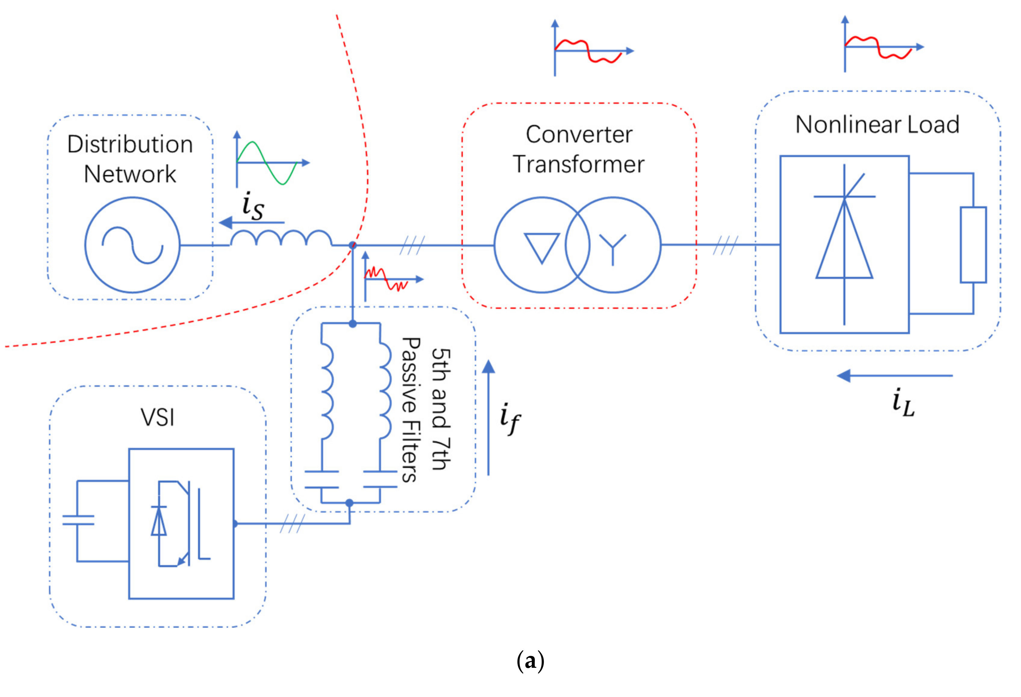
Figure 1 gives the circuit topologies of the distribution networks considering the HAPF and HIAF system, respectively. As is shown in
Figure 1a, the filtering system is usually installed at the grid’s side of the converter transformer. The filtering system is composed of active filters and LC passive filters. The passive filters can filter out the 5th and 7th harmonics. The active filters are mainly used to improve the filtration performance of the passive filters.
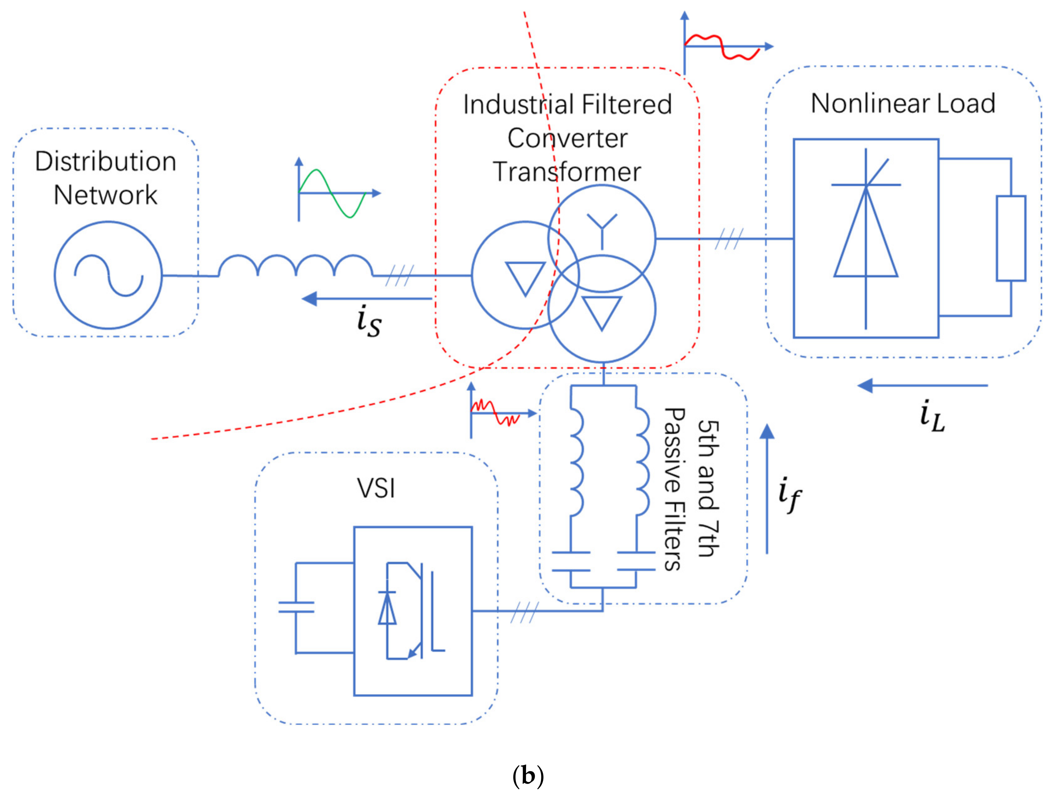
Figure 1b presents the topology of the proposed HIAF system with the Ddy transformer. Unlike the conventional HAPF, the proposed HIAF system uses the three-winding inductive filter transformer. The grid-side windings use the D connection, while the load-side windings use the Y connection. When the low-voltage distribution network is connected with unbalanced loads, the load-side windings can also use the Yn connection.
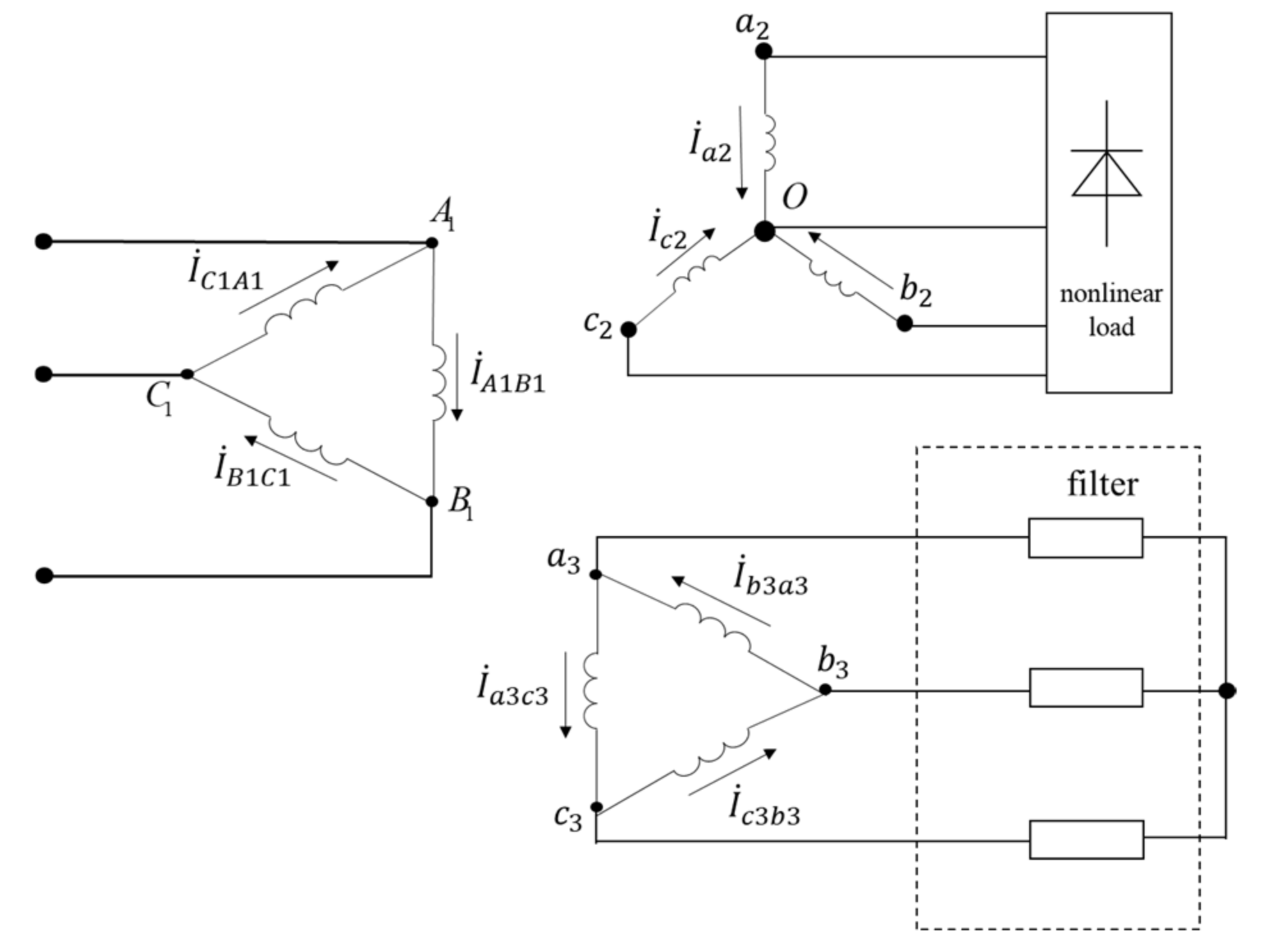
Figure 2 shows the circuit topology of the novel filtering winding. It uses the zero-value impedance design and the D connection. The filtering winding is connected in series with the fully tuned branch and voltage source inverter. The 5th and 7th fully tuned filtering branch are connected in parallel.
The proposed HIAF system in this paper has the following features:
(1) The filtering winding adopts a zero-value impedance design; hence, the harmonic current is balanced between the load-side and filter-side windings. Harmonic currents can barely flow into grid-side windings. Therefore, the harmonic currents’ adverse effects on converter transformers are significantly reduced.
(2) The fully tuned filtering branches do not require a biased design, such as filtering branches, in traditional filtering systems. The parameters of the fully tuned filtering branches can be calibrated based on the desired tuning frequency.
(3) The filtration performance of the traditional filtering systems is highly susceptible to the system parameters, which may cause harmonic amplification when the system has low impedance regarding the filtering system. In the proposed HIAF system, the fully tuned filter branch is paralleled with the grid-side winding and system impedance of the convertor transformer; hence, the HIAF system has an anti-resonance capability. Meanwhile, with the aid of virtual impedance control, the HIAF system can reduce the background grid-side harmonic voltage and improve the operation of the fully tuned filtering branches. Compared with inductive filters, the HIAF has low sensitivity towards the background harmonics.
(4) The Ddy wiring scheme maintains traditional transformers’ ability to attenuate high-order harmonic currents (particularly the 3rd-order harmonic current). On the other hand, the voltage source inverter and the fully tuned branch can improve the power quality by suppressing the harmonic current and reactive power.
(5) Due to the manufacturing restriction, fully controlled power devices are usually with low voltage levels. Hence, passive compensation is widely used in power systems with medium or high voltage levels. The HIAF system has active inverters on the filter windings and reduce the DC voltage. Hence, low-voltage fully controlled devices can be used. Moreover, the HIAF system reduces the number of power devices (connected either in parallel or in series) and save installation costs.
(6) Because the grid-side and filter-side windings of the transformer adopt the same connection group, there is no need for phase compensation between the harmonic detection point and the compensation point. Hence, it is conducive to simplifying the complexity of the voltage source inverter (VSI) control system.
3. Structure and Operation Principle of the Hybrid Inductive and Active Filter System
Equivalent Circuit of the Proposed Hybrid Inductive and Active Filter System
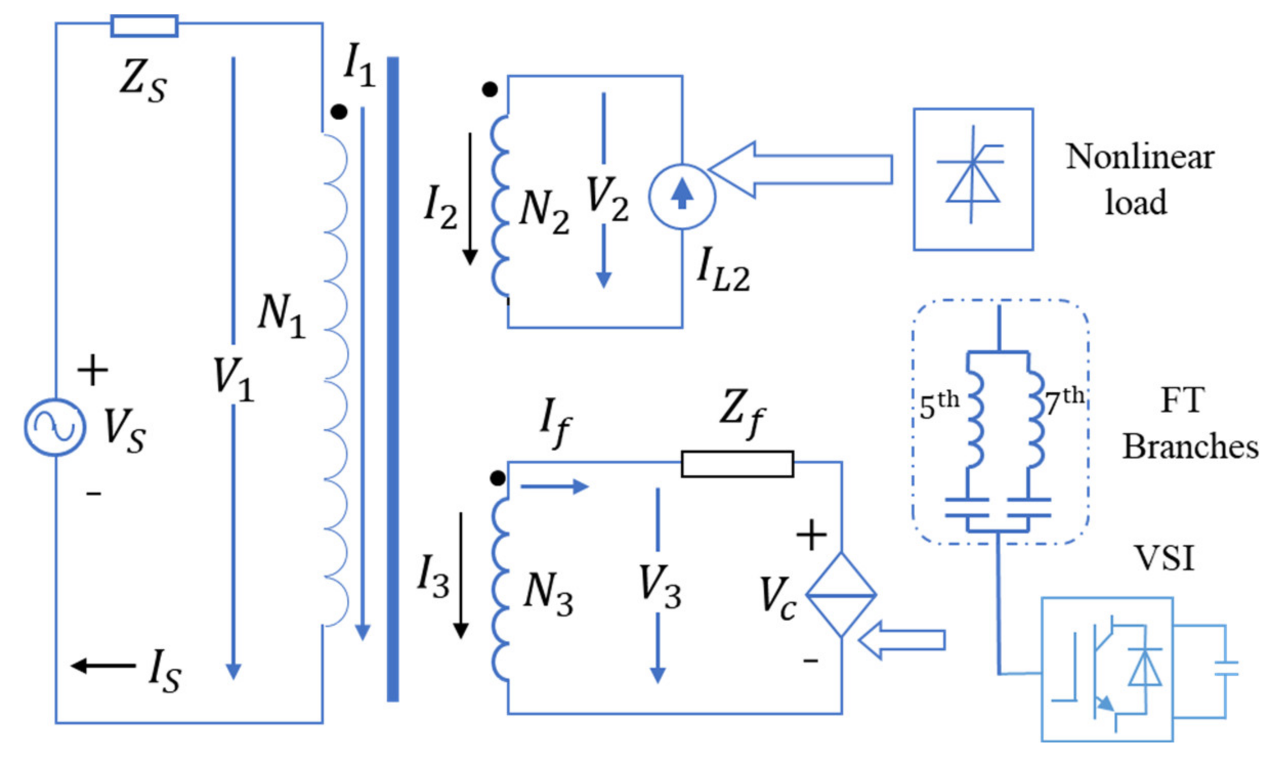
Figure 3 shows the schematic of the single-phase topology of an HIAF system.
and
denote the grid-side voltage and current.
represents the system impedance.
and
denote the load current and filtering branch current.
is equivalent impedance for 5th and 7th harmonic filtering branches in parallel connection. Vc is the output voltage on the AC side of the VSI:
where
n denotes the order of the harmonic;
denotes the grid-side harmonic current;
and
are the 5th and 7th harmonic currents in the filtering branch, respectively;
K represents the harmonic damping control coefficient; and
and
represent the zero-value impedance control coefficient for the 5th and 7th harmonic currents, respectively.
Based on the operation of the multi-winding transformer, it follows that
where
represents the equivalent grid-side voltage of the first secondary winding;
represents the equivalent grid-side current of the load-side winding;
represents the equivalent grid-side current of the filter-side winding;
represents the equivalent impedance between the grid-side and load-side windings; and
represents the equivalent impedance between the grid-side and the filter-side windings.
Considering the electromagnetic balance of the transformer, the winding currents satisfy the following condition by ignoring the excitation current:
where
,
, and
represent the winding number of the grid-side (primary) winding, the winding number of the load-side (secondary) winding, and the winding number of the filter-side (secondary) winding, respectively; and
,
, and
represent the winding current of the grid-side (primary) winding, the winding number of the load-side (secondary) winding, and the winding number of the filter-side (secondary) winding, respectively.
Based on Kirchhoff Circuit Laws, it follows that
The mathematical model of the HIAF is given in (1) to (5). The model mainly describes the relations between the voltage, current, and impedance of the different windings and branches.
The equivalent grid-side load current of the transformer can be expressed by
Considering the grid-side harmonic voltage
and load-side harmonic current
, the grid-side harmonic current can be expressed by
where
represents the grid-side harmonic current;
represents the equivalent grid-side current of the load-side harmonic current; and
is the equivalencing coefficient of the virtual impedance
. From (7) it can be seen that
is dependent upon the filter winding impedance
, the filtering branch impedance
, and the harmonic damping control factor
.
If only the fully tuned filtering branch operates, K is equivalent to zero. Taking the 5th harmonic current as an example, becomes zero due to the fully tuned resonance in the denominator of the first fraction of (7). The zero-value impedance design will make . Hence, the first fraction of (7) is mainly dependent on the system impedance and the transformer′s grid-side equivalent impedance . Therefore, the filtering branch in this situation will easily resonate with the system under small parameter perturbation. Then, a large harmonic current, , can be generated even under a small background harmonic voltage, . As for the second fraction of (7), the denominator has a similar evolution, and its decrease will increase the harmonic currents . By the aid of the IDAF, we can select a large K value to decrease the harmonic currents . Even if the system parameter varies with the perturbation, will not significantly grow due to the large K.
In the ideal voltage scenario where the harmonic voltage is ignored on the grid-side winding,
can be simplified as
To achieve the complete filtration of the harmonics, (8) shows that should be satisfied. An alternative is to choose a large K.
4. Controller Design and Parameter Tuning
As is shown in
Figure 1b, the core components in the proposed HIAF system are the inductive filter transformer, fully tuned filtering branch, and the VSI. The filtering winding and fully tuned branch offer the superconducting closed loop with negligible impedances. The VSI can improve the filtration performance by adjusting the harmonic damping control coefficient
K. It can prevent the resonant amplification of the harmonics on the grid’s side of the transformer. Following is the detailed procedure for parameter tuning and VSI control.
4.1. Impedance Tuning of the Filtering Winding and Fully Tuned Filtering Branch
As for the impedance,
for a practical transformer; we can optimize the structure of the transformer to minimize it. Specifically, the resistor
can be fully reduced by increasing the cross-sectional area of the conductor or improving the conductivity. By adjusting the short-circuit impedance, the reactance
can be tuned to 0. The adjustment of either
or
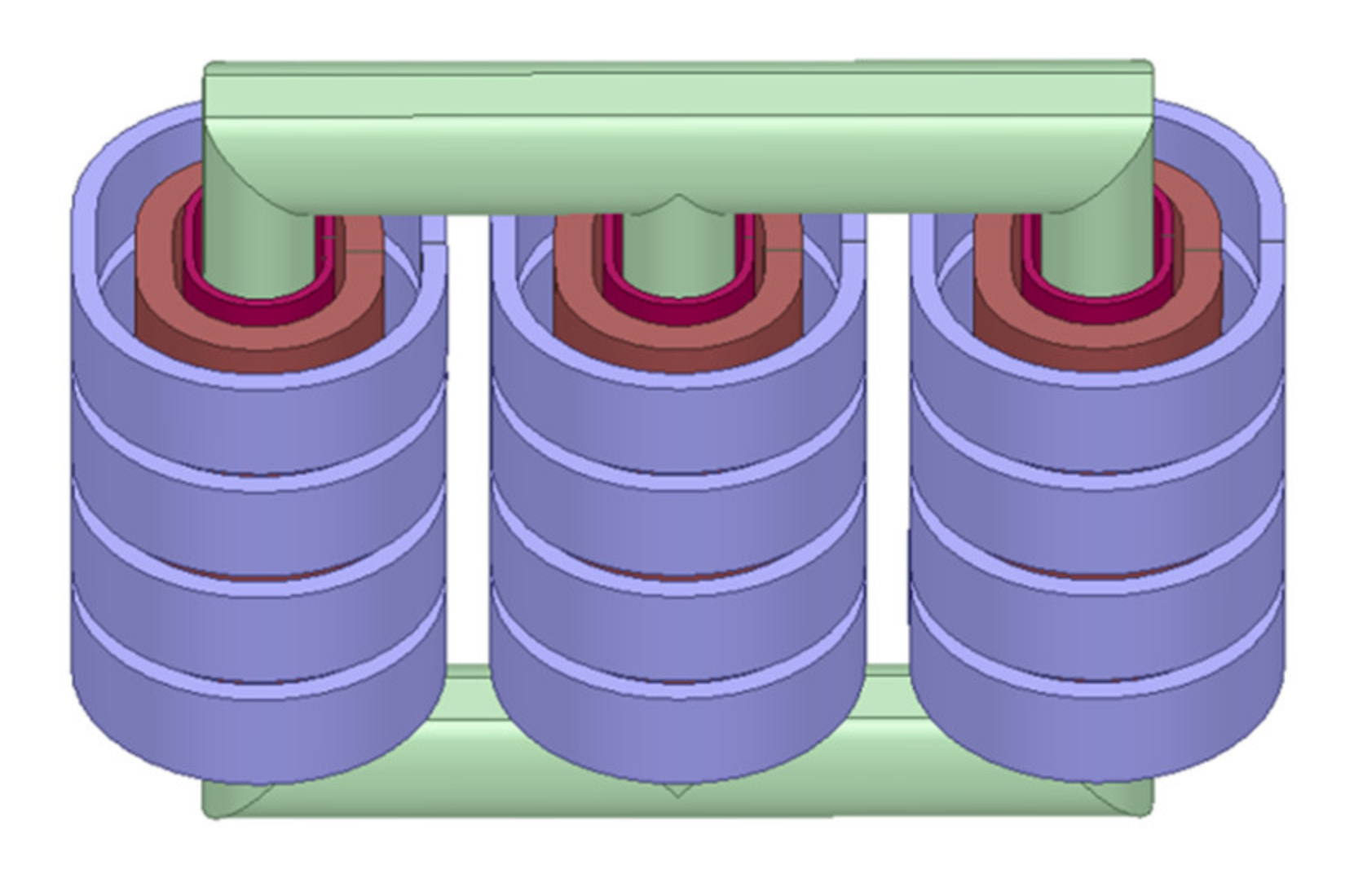
can be achieved by the simulation toolkit. In this paper, we use ANSYS/Maxwell to design the 3D model of the transformer shown in
Figure 4. We used the energy-based impedance measuring method to obtain the desired impedance that can achieve the filtration, since the main characteristic harmonics caused by the nonlinear loads in the studied system are the 5th and the 7th harmonics. Hence, we built the fully tuned filtering branch to filter out the 5th and the 7th harmonics. The filter parameters can be calculated by
where
represents the fundamental frequency;
represents the input voltage of the filtering branch; and
represents the reactive power compensation in the filtering branch. The filtering branch can guarantee the full resonance at the specified harmonics, so there is no need for a bias tuning design, and the higher the quality factor, the better; that is, the smaller the internal resistance of the filter branch, the better.
4.2. Filtration Performance Analysis Considering Different K
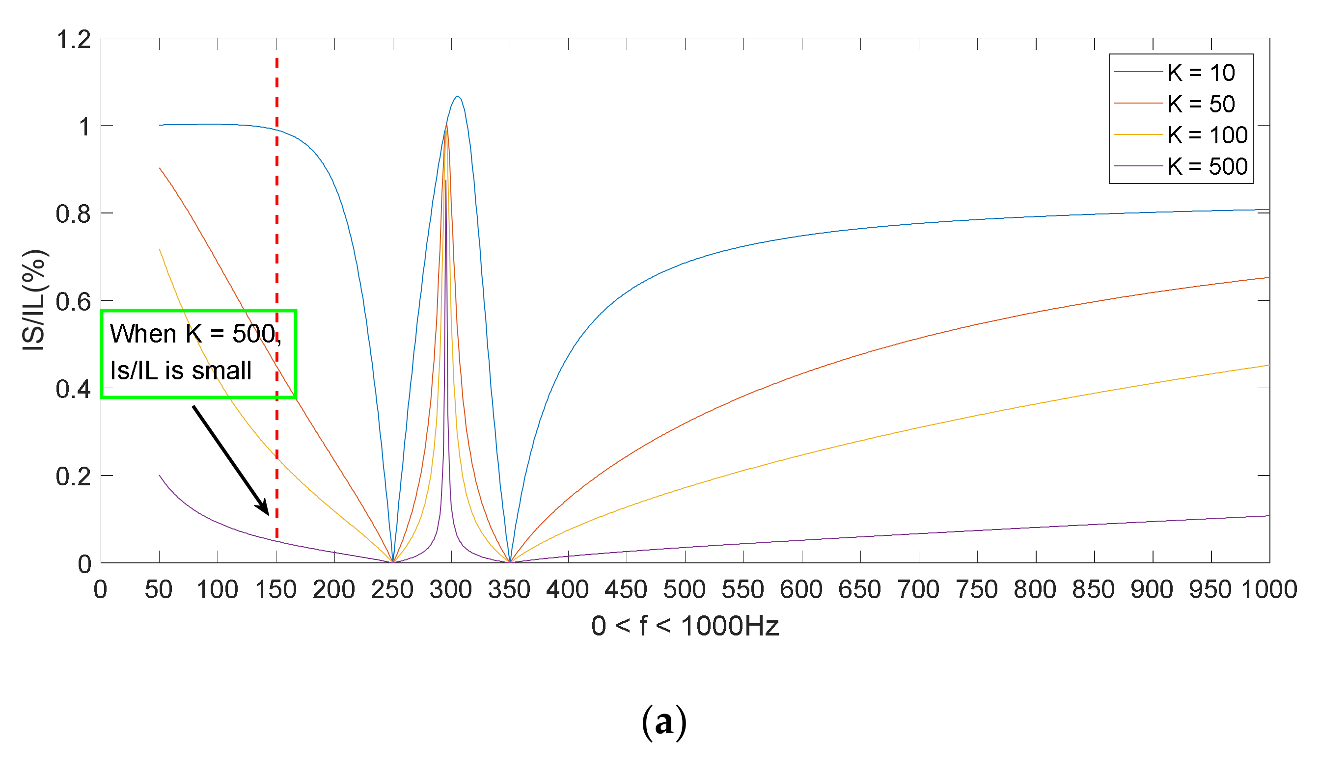
We establish a sensitivity function to quantify the relation between the grid-side harmonic current and grid-side harmonic voltage (load-side harmonic current):
Equation (10) implies that the damping control coefficient K plays a significant role in the harmonic filtering.
Figure 5 shows the sensitivity function values under a different
K. With our designed 30 kVA inductive filter transformer and filtering systems (the setups and parameters will be detailed in Section V), we calculate (10) for the frequency ranging from 0 to 1000 Hz. Then we draw the sensitivity curves under a different
K. With the increase in
K, it shows that
becomes more irrelevant with
and
, even the frequency deviates from the resonant frequency. That is to say, the increase in
K causes the low impedance of the filtering system. The influence of
and
upon
also decreases with the increase in
K; thus, the filtration performance is improved. In summary, we can increase
K to filter out the 3rd, 5th, and 7th harmonics caused by the nonlinear loads.
Figure 5a shows that when
K = 500, the 3rd load-side harmonic currents almost have no influence upon the 3rd grid-side harmonic currents.
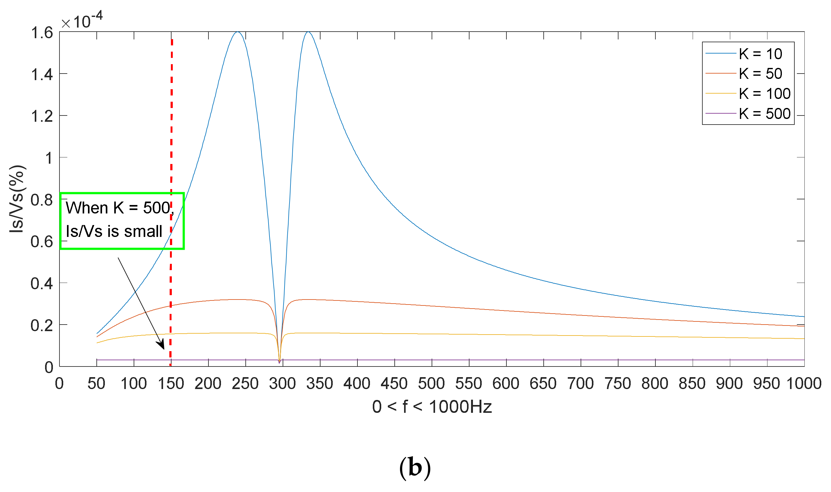
From
Figure 5b, it can be learned that the grid-side harmonic current
is susceptible to the grid-side harmonic voltage
. Harmonic resonance or amplification will probably occur in a certain area; but, the increasing
K can reduce the risk of harmonic resonance. In summary, the proposed HIAF system can reduce the impact of the background harmonic voltage and prevent the harmonic amplification caused by the harmonic resonance between the filter and the network.
Figure 5 also shows that when
K is sufficiently large, the load-side harmonic currents
and grid-side harmonic voltages
will no longer affect the grid-side harmonic currents; that is, increasing
K will bring few marginal gains. In fact, in the VSI control system,
K is closely related with the AC output voltage of VSI. Exorbitant
K will lead to system oscillation or another instability phenomenon.
4.3. Voltage Source Inverter Control System Design
4.3.1. Harmonic Damping Control of the Voltage Source Inverter
Unlike the conventional HAPF, the harmonic detection and compensation points are usually located at the (1) grid-side and filter-side of the transformer; and (2) load-side and filter-side of the transformer. When the detection and compensation points adopt different connection modes, the conventional instantaneous reactive power-based detection methods will be inapplicable. We need to collect the phase information at the detection and compensation points (as shown in
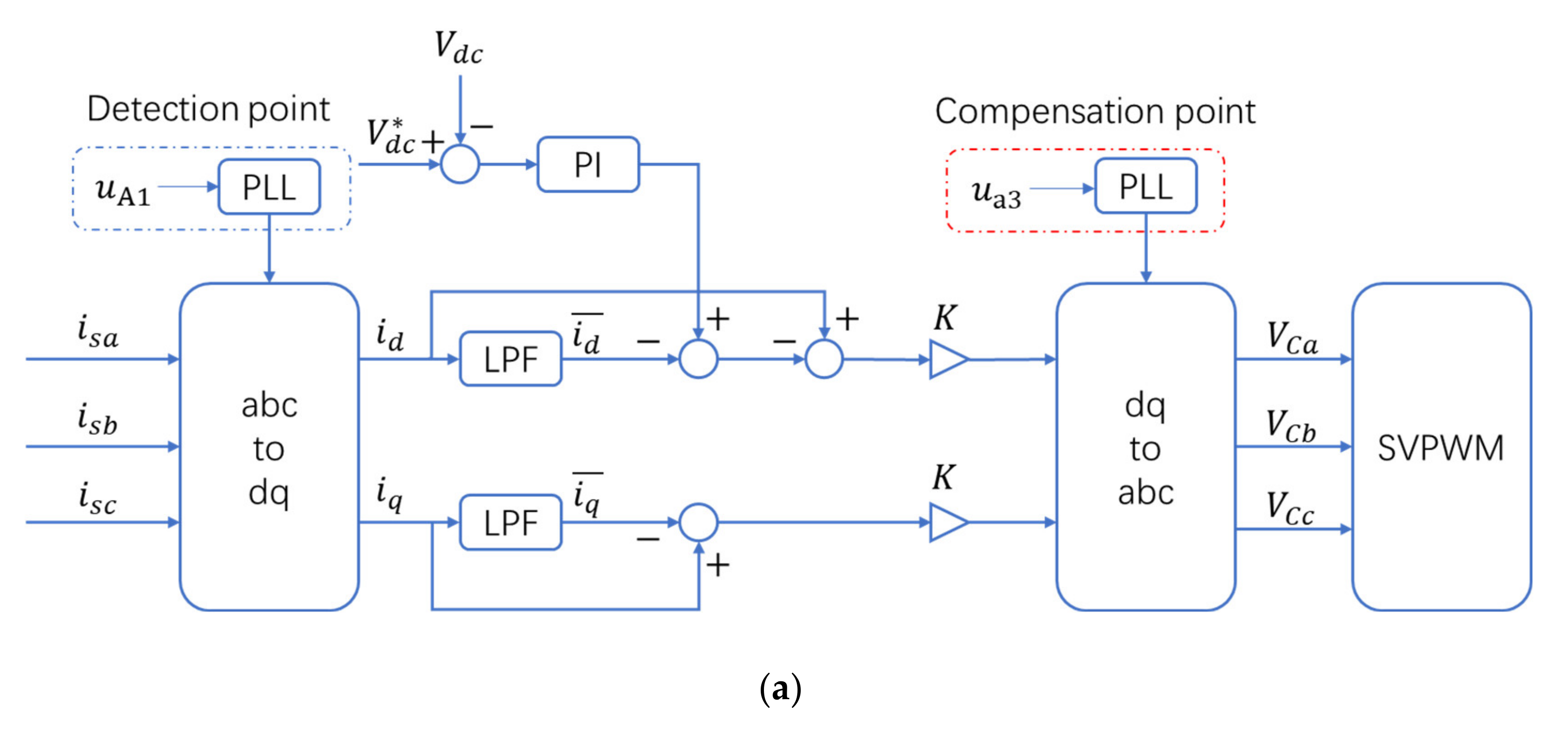
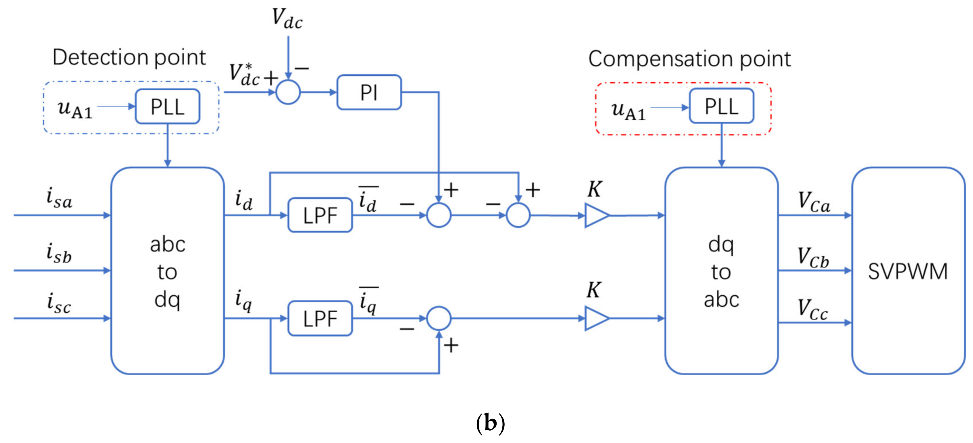
Figure 6a), to handle the spatial difference between the detection and the compensation points.
In the proposed HIAF system, both the grid-side and filter-side windings adopt the D connection mode. We select the grid-side winding as the detection point while the filter-side winding as the compensation point. No phase compensation is required since the spatial difference is negligible.
Figure 6b gives the overall schematic diagram of the VSI controller. The controller uses the voltage and current sensors to measure the three-phase currents (
,
,
) and voltages (
,
,
). Based on the measured voltages and PLL, we can get the phase, which is used as the reference phase in
dq transformation, at the detection point. The fundamental voltage components can be obtained by feeding the transformed
dq currents into the filter. The reference voltage is then calculated by multiplying the detected harmonic components with the harmonic damping control coefficient
K.
K can be regarded as a virtual impedance connected in series with the system impedance
. It can increase the grid-side equivalent impedance and suppress the harmonic resonance.
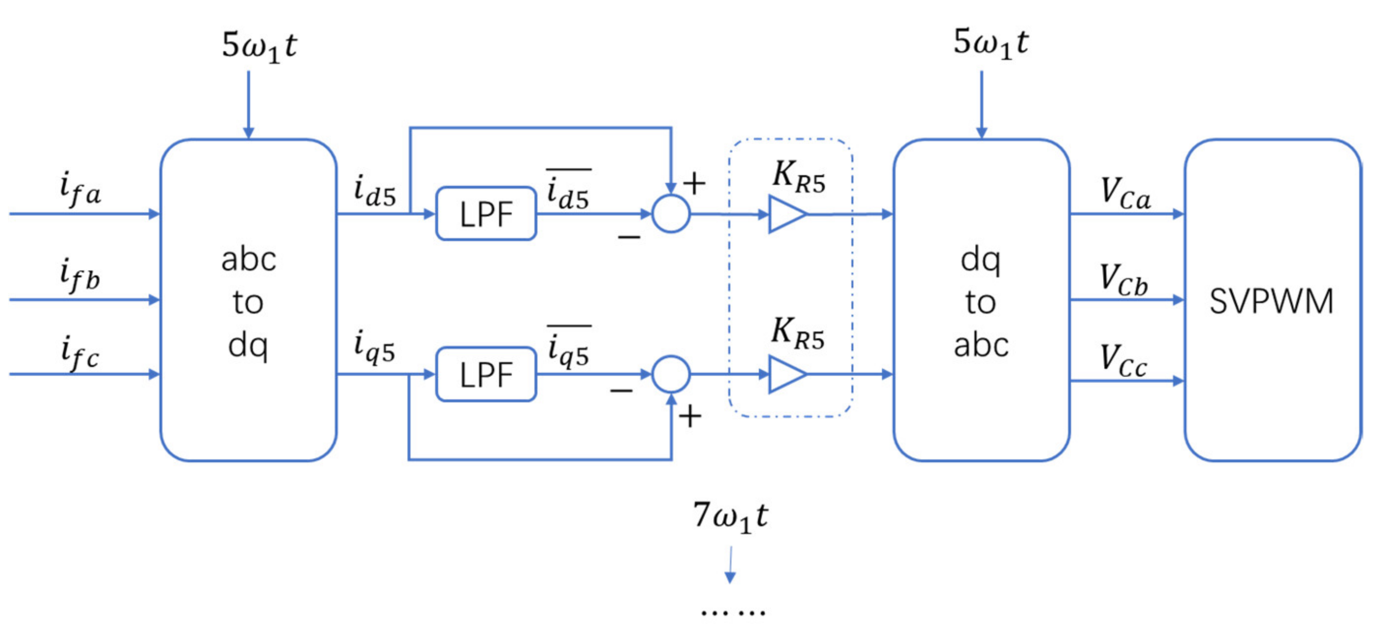
4.3.2. Zero-Value Impedance Control of the Voltage Source Inverter
Figure 7 shows block diagram of the zero-value impedance control system of the proposed HIAF system. We can calculate the 5th and 7th harmonic components flowing into the passive filter by measuring the three-phase currents in the filtering branch. Then the reference voltage is computed by multiplying the harmonic components with gain
(
n = 5 and 7).
Specifically, the voltage
of the passive filter for the
nth harmonic components can be expressed by
where
represents the fundamental frequency, and
denotes the internal resistor of the filtering branch.
If the full resonance is achieved in the filtering branch, (11) can be rewritten by
It can be seen that becomes zero if is the same as . The zero-value impedance control coefficient can be regarded as a virtual impedance connected in series with the internal impedance of the filtering branch. Hence, the quality factor of the fully tuned filtering branch will be significantly elevated, and the filtration performance is further enhanced.
5. Case Study
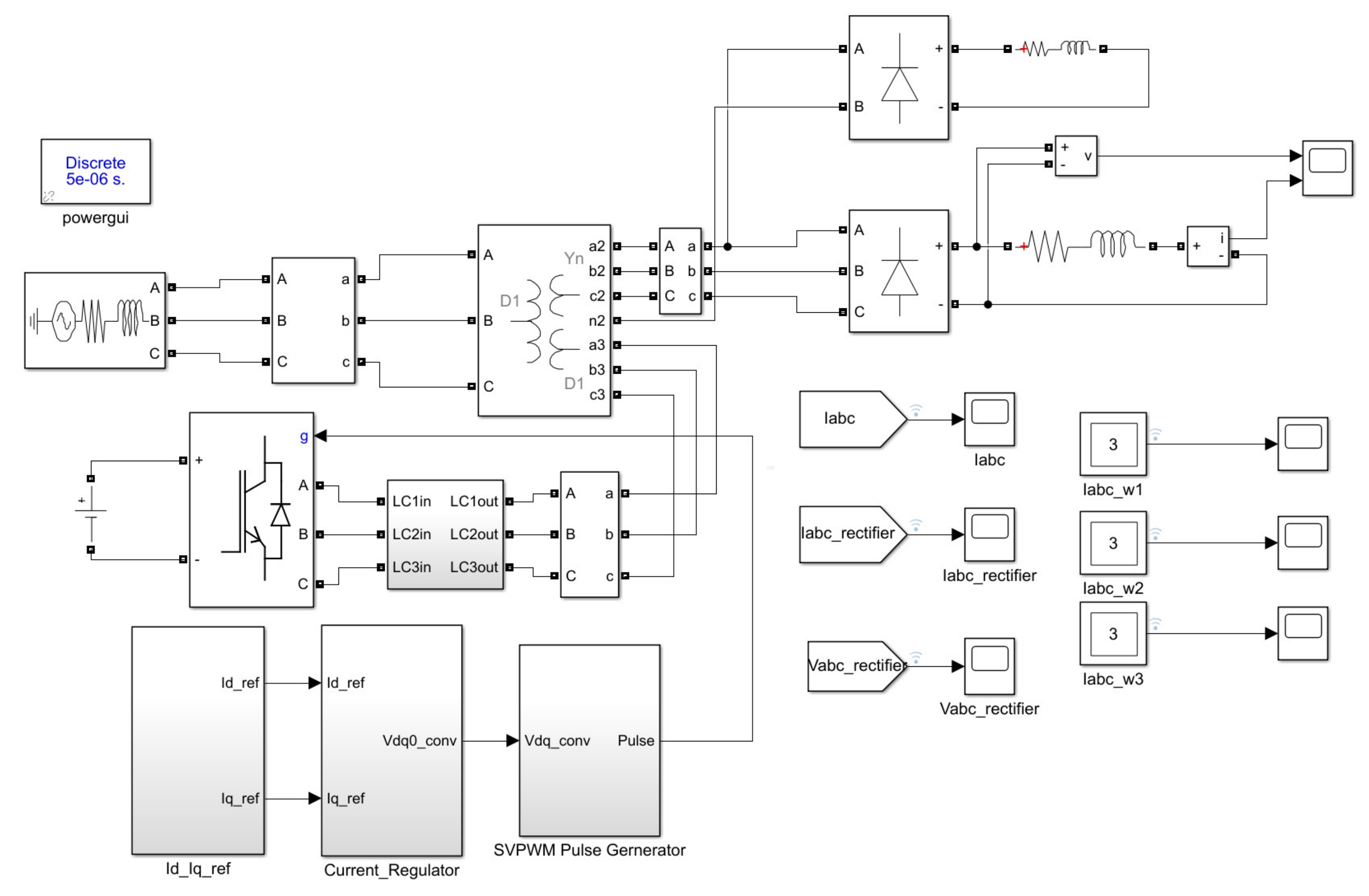
In order to verify the above theoretical analysis and demonstrate the performance of the proposed filtering system, a transient simulation model of the low-voltage distribution network considering a three-phase unbalanced load was established by using the MATLAB/SIMULINK simulation tool. The block diagram of the system is shown in
Figure 8. The parameters of the inductive filter transformer and filtering branch are shown in
Table 1 and
Table 2, respectively.
In the simulation case, the filtering effects of the inductive filter and the proposed HIAF system were compared.
5.1. Filtration Performance Considering Balanced Three-Phase Loads
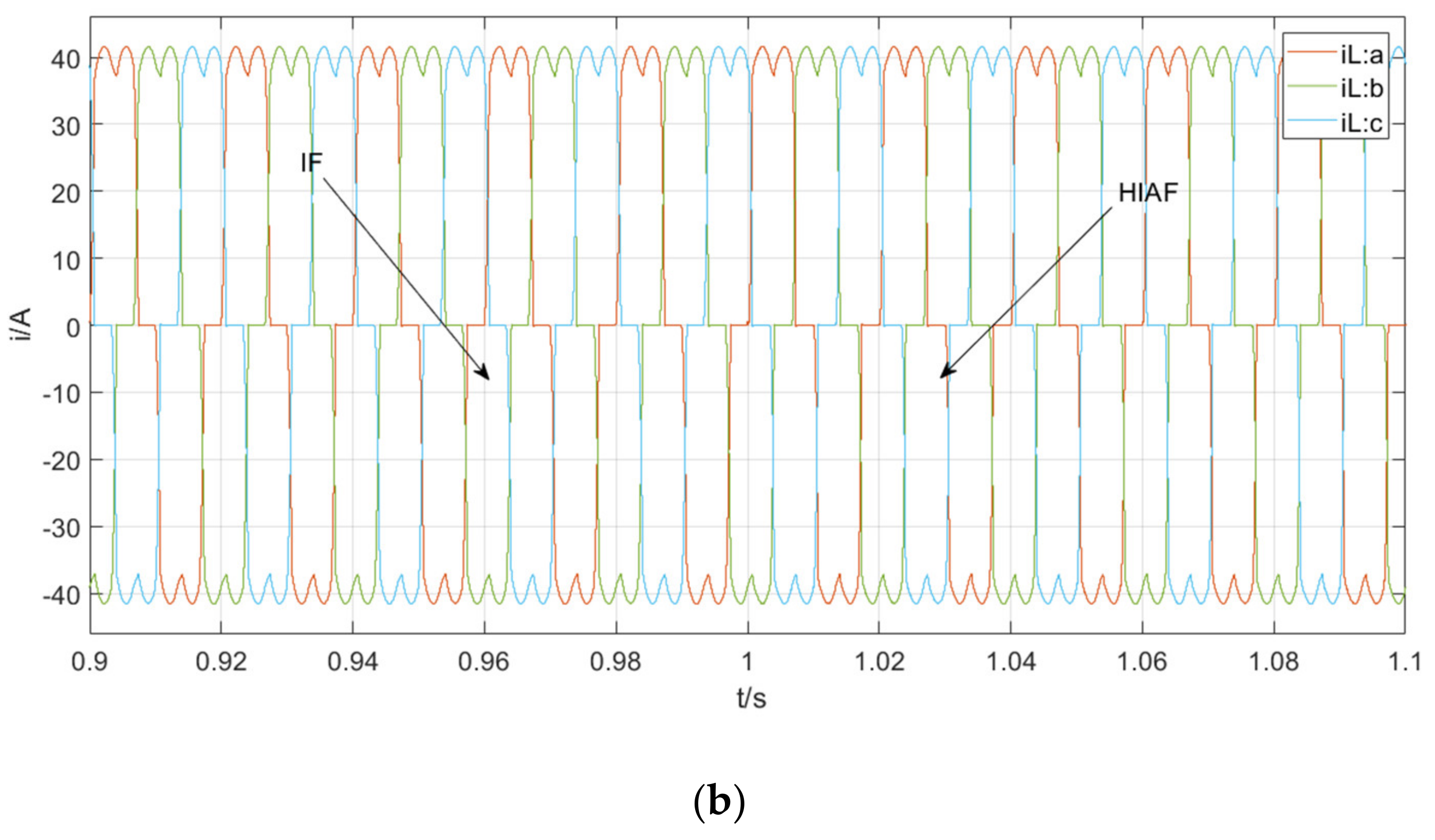
Figure 9 shows the waveform of a grid-side current and load-side current simulated by the Ddy connection transformer using HIAF technology and its filtering system.
Figure 9b shows that the load-side current contains a large number of harmonic components.
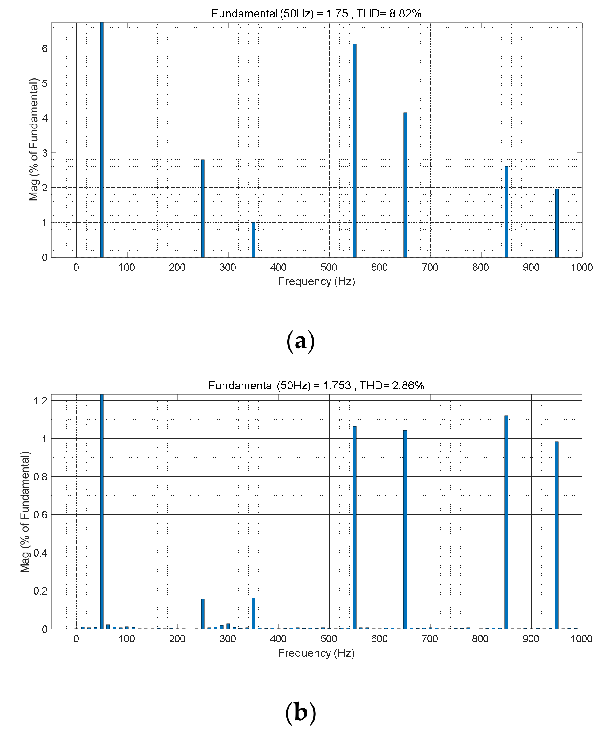
Figure 9a shows that when the system connects the 5th and 7th fully tuned filtering branches in the filter-side winding (before 1 s), some harmonic components are filtered out, and the current distortion rate is shown in
Figure 10a. By connecting the HIAF system (after 1 s), the harmonic currents of the grid-side winding are significantly reduced, and the current distortion rate is shown in
Figure 10b. It is worth mentioning that the system is in a three-phase load balance, so the current does not contain 3rd, 9th, and 15th harmonics. It shows that the HIAF system can enhance the filtration performance and make the power grid current waveform present a good sinusoidal curve.
5.2. Filtration Performance Considering Unbalanced Three-Phase Loads
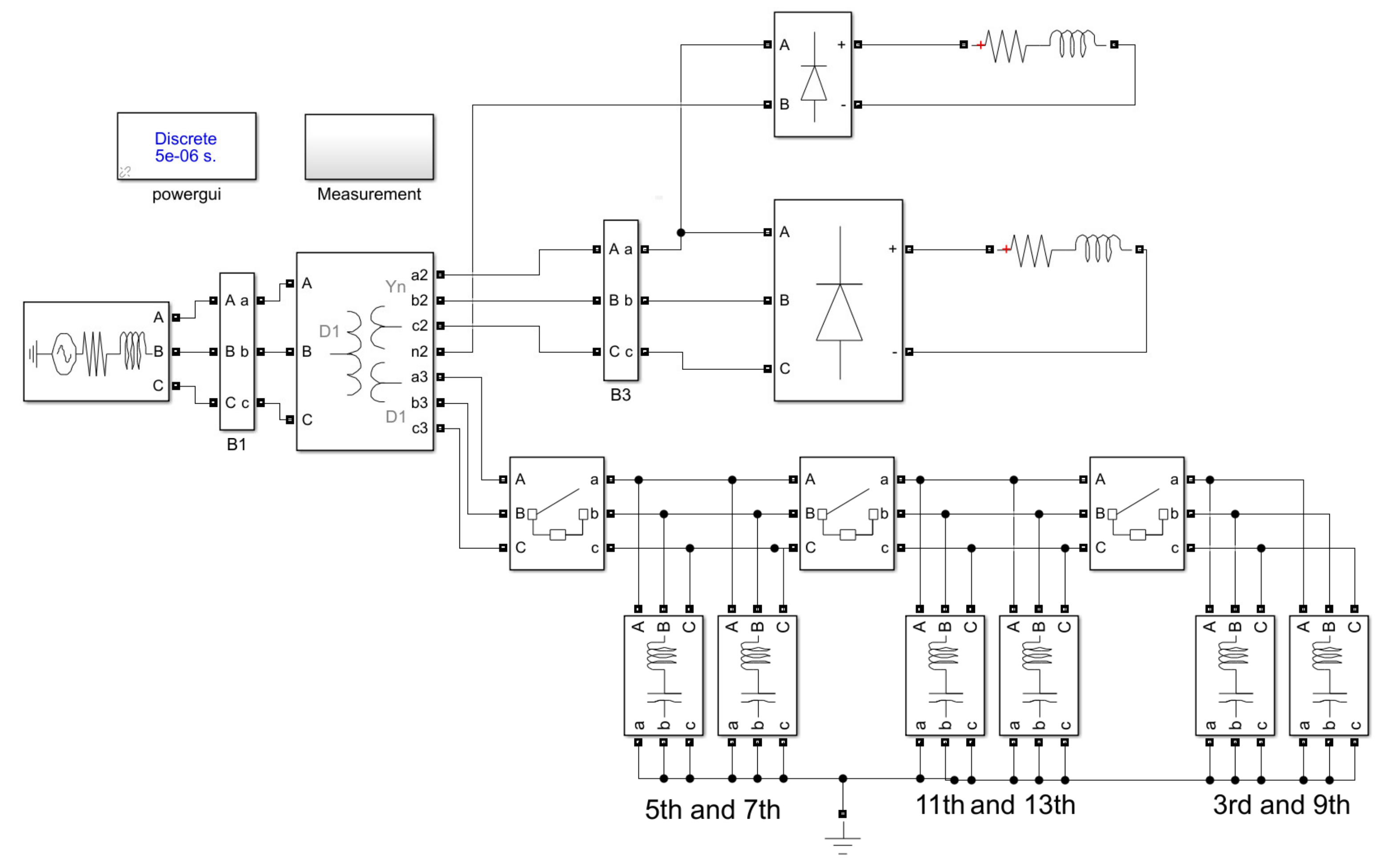
We further built the IF system, which is shown in
Figure 11, to compare with our proposed HIAF system. Both systems adopt the same loading conditions. The IF system is sequentially integrated with the following three types of filtering branches: (1) the combined 5th and 7th filtering branches; (2) the combined 11th and 13th filtering branches; and (3) the combined 3rd and 9th filtering branches.
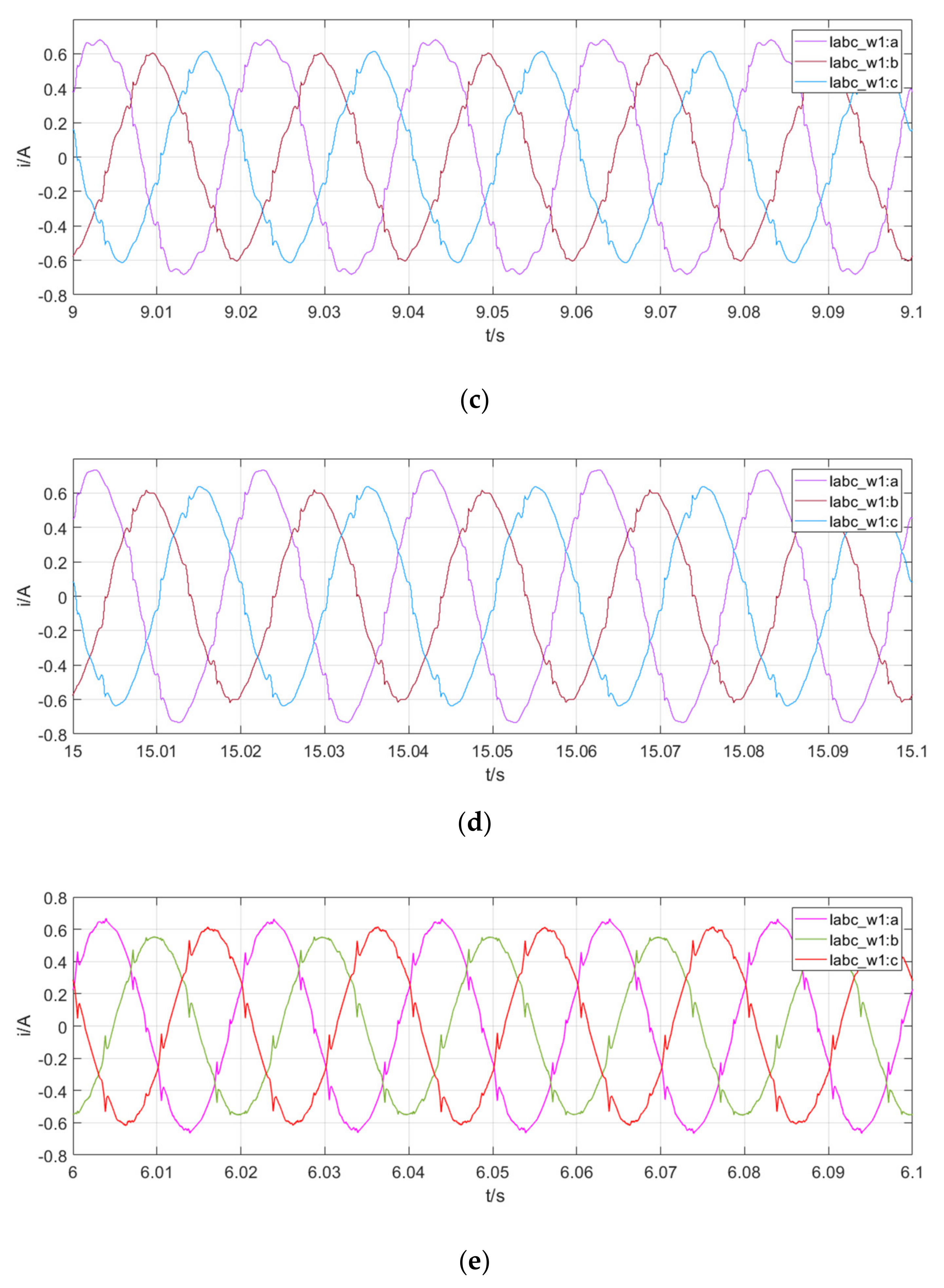
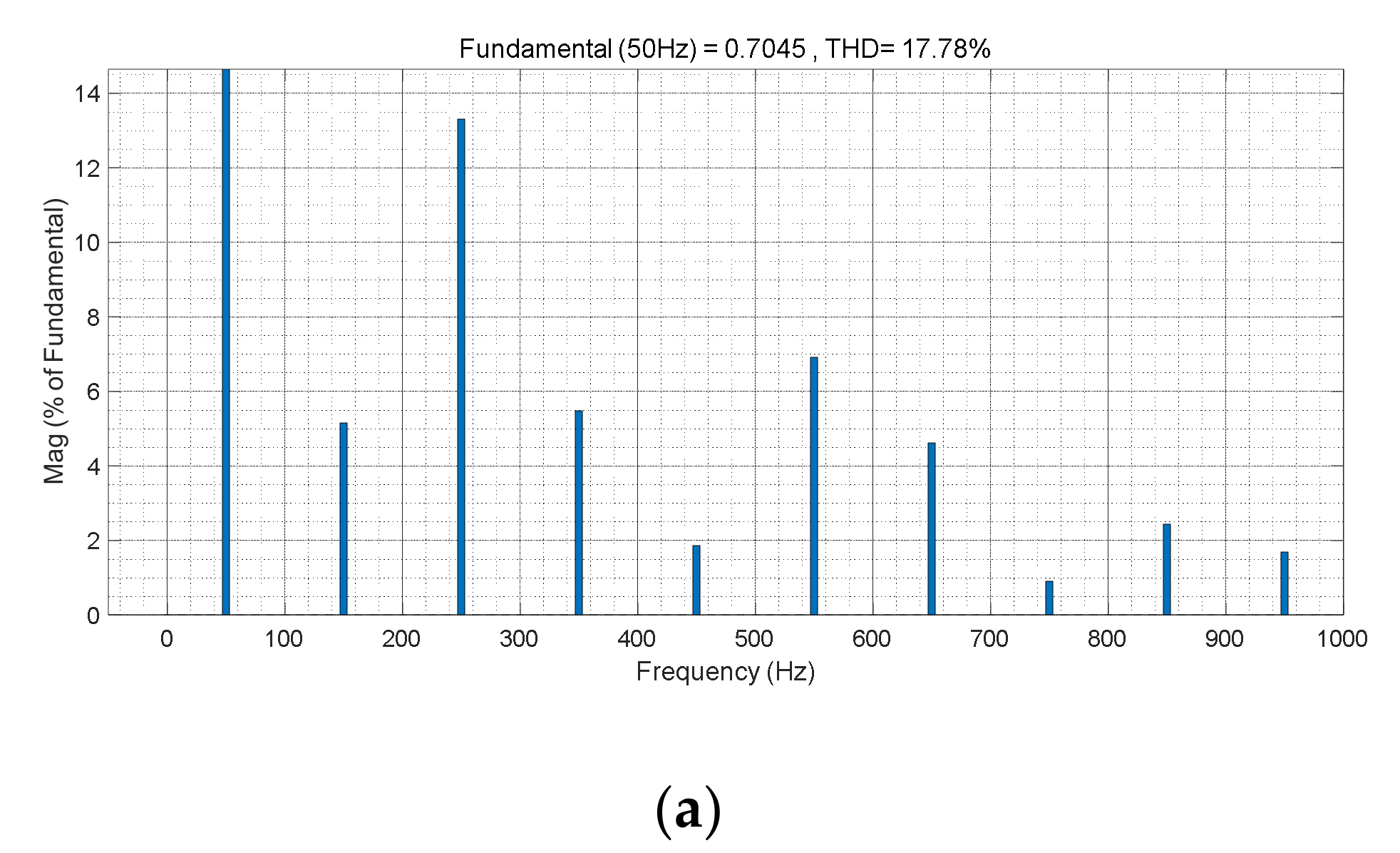
Figure 12 and
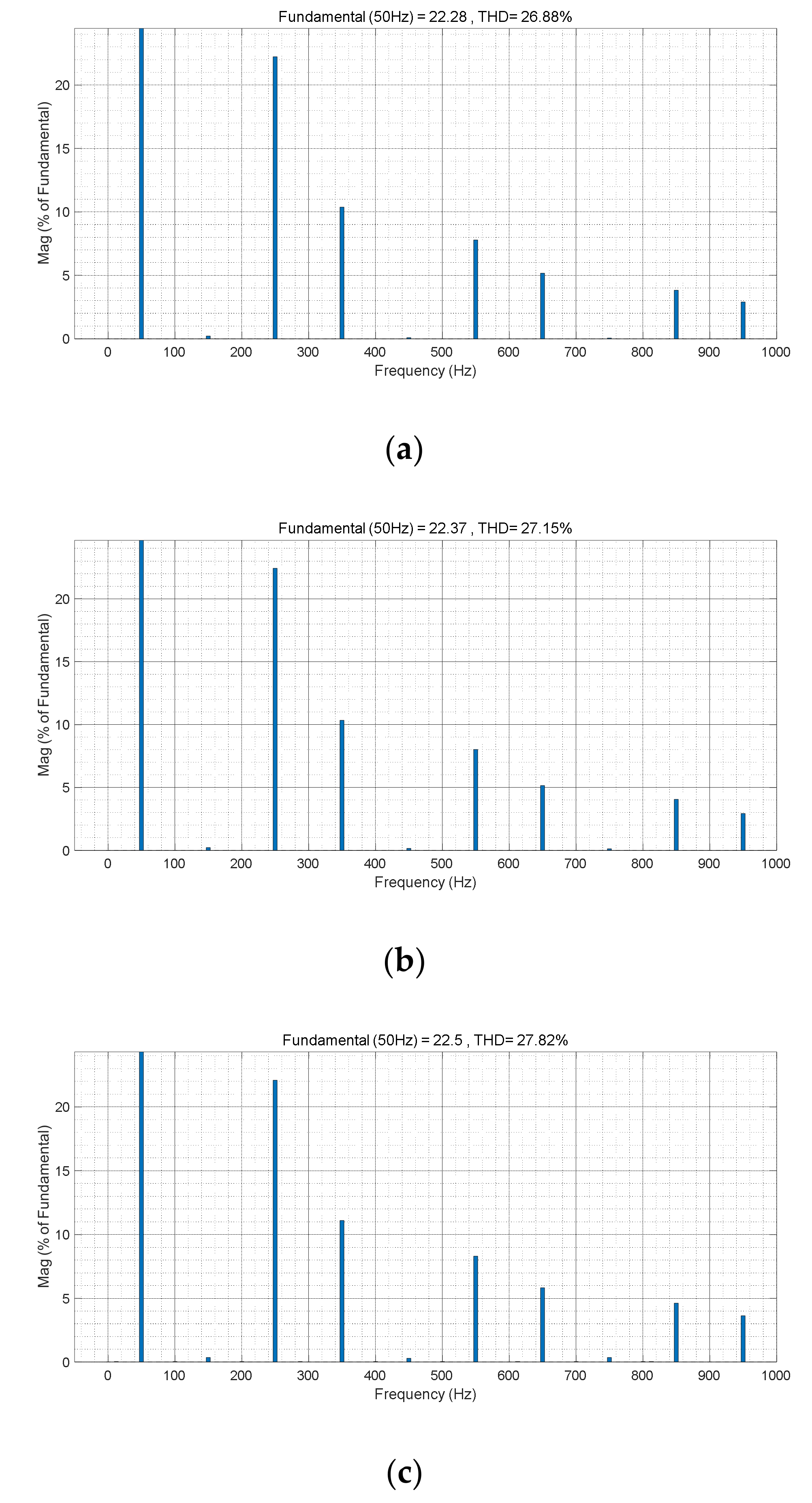
Figure 13 show the current waveform and distortion rate of the transformer’s grid-side winding when different filtering devices are used.
Figure 12a and
Figure 13a show that the grid-side winding currents contain a large number of harmonics with unbalanced loads. The distortion rate is 17.78%, and the currents contain 3rd harmonic components.
Figure 12b and
Figure 13b show the grid-side winding current and its distortion rate when the 5th and 7th fully tuned filtering branches are connected. As can be seen, the harmonic components are further filtered out, but the current distortion rate is still as high as 10.19%. It can be seen that the 5th and 7th harmonics are partially compensated while the 11th and 13th harmonics are untouched. The currents also have 3rd and 9th harmonics.
Figure 12c and
Figure 13c show the grid-side current and its distortion rate after integrating the combined 11th and 13th filtering branches. It can be seen that most harmonics, including the 5th, 7th, 11th, and 13th harmonics, are filtered out. The 3rd harmonics are untouched since the combined 3rd and 9th filtering branches are not integrated in this context.
Figure 12d and
Figure 13d show the gird-side current and its distortion rate after integrating all combined filtering branches. It can be seen that the filtering performance is unacceptable since the 3rd and 9th harmonics are only partially filtered.
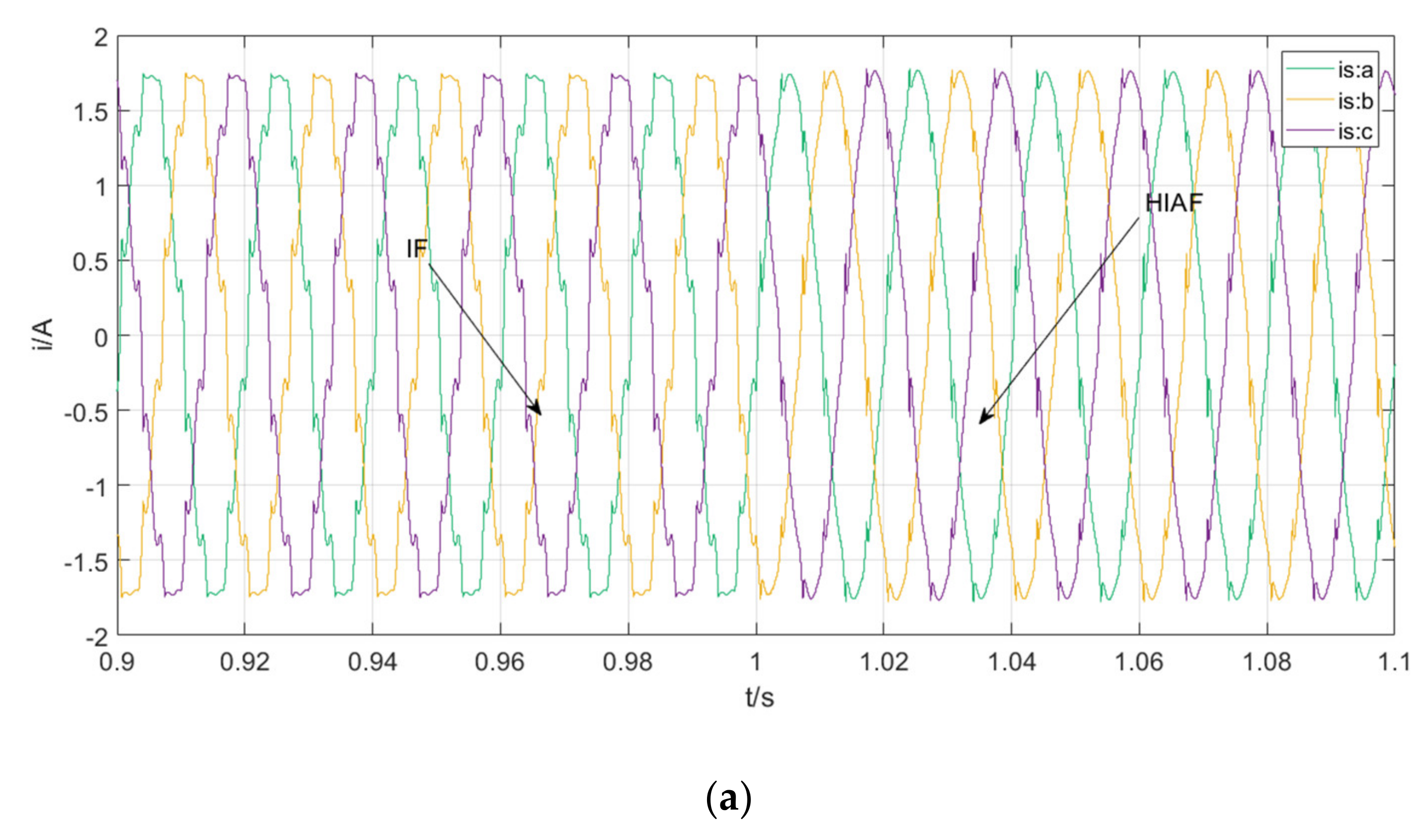
Figure 12e and
Figure 13e show the current waveform and distortion rate of the transformer’s grid-side winding under the HIAF system. The three-phase winding currents under this context are sinusoidal, and the distortion rate is reduced to 3.24%. The 3rd harmonic distortion rate is reduced to 0.4%, indicating the effective suppression of the 3rd harmonic currents.
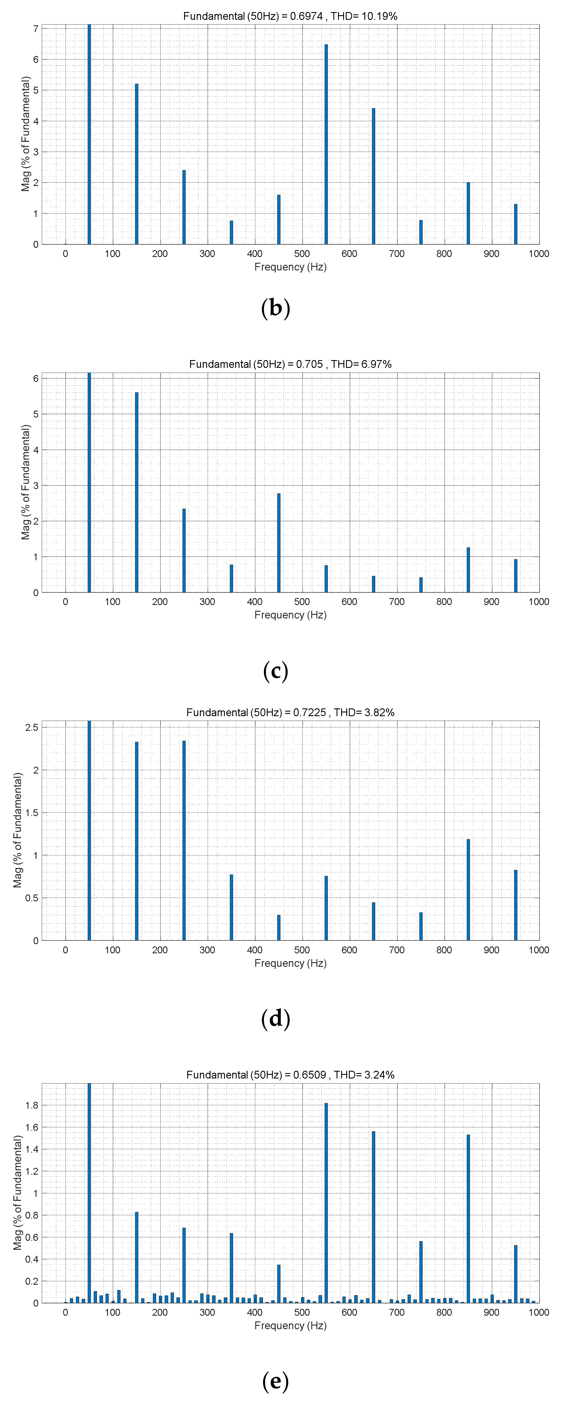
Figure 14 and
Figure 15 show that the load-side winding currents contain a large number of harmonics under different filtering devices, and the distortion rate can be as high as 25%. The above data show that under an unbalanced load, the inductive active filtering devices can effectively prevent harmonic currents from flowing into the transformer’s grid-side winding. It can avoid harmonic pollution on the grid side and make the grid current waveform present a good sinusoidal curve.
The aforementioned comparison results show that the impedance characteristic is inflexible due to the inherently unchanged characteristics of the filtering system. The characteristic of the filtering branches is improved by the control of VSI; hence, the filtering performance is greatly enhanced.
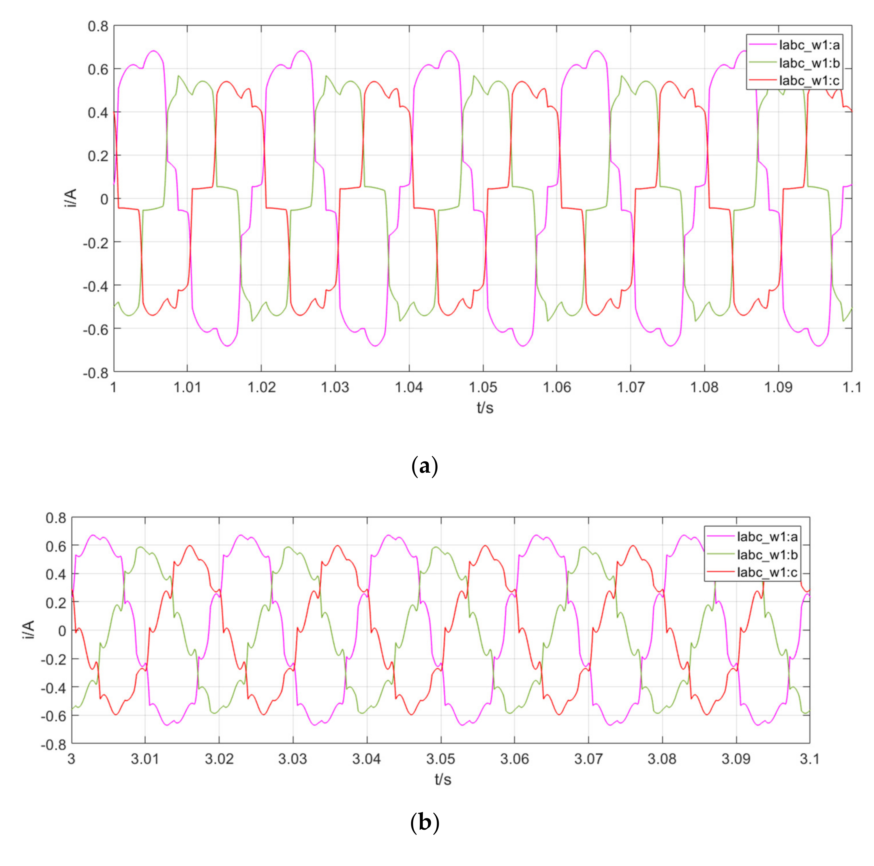
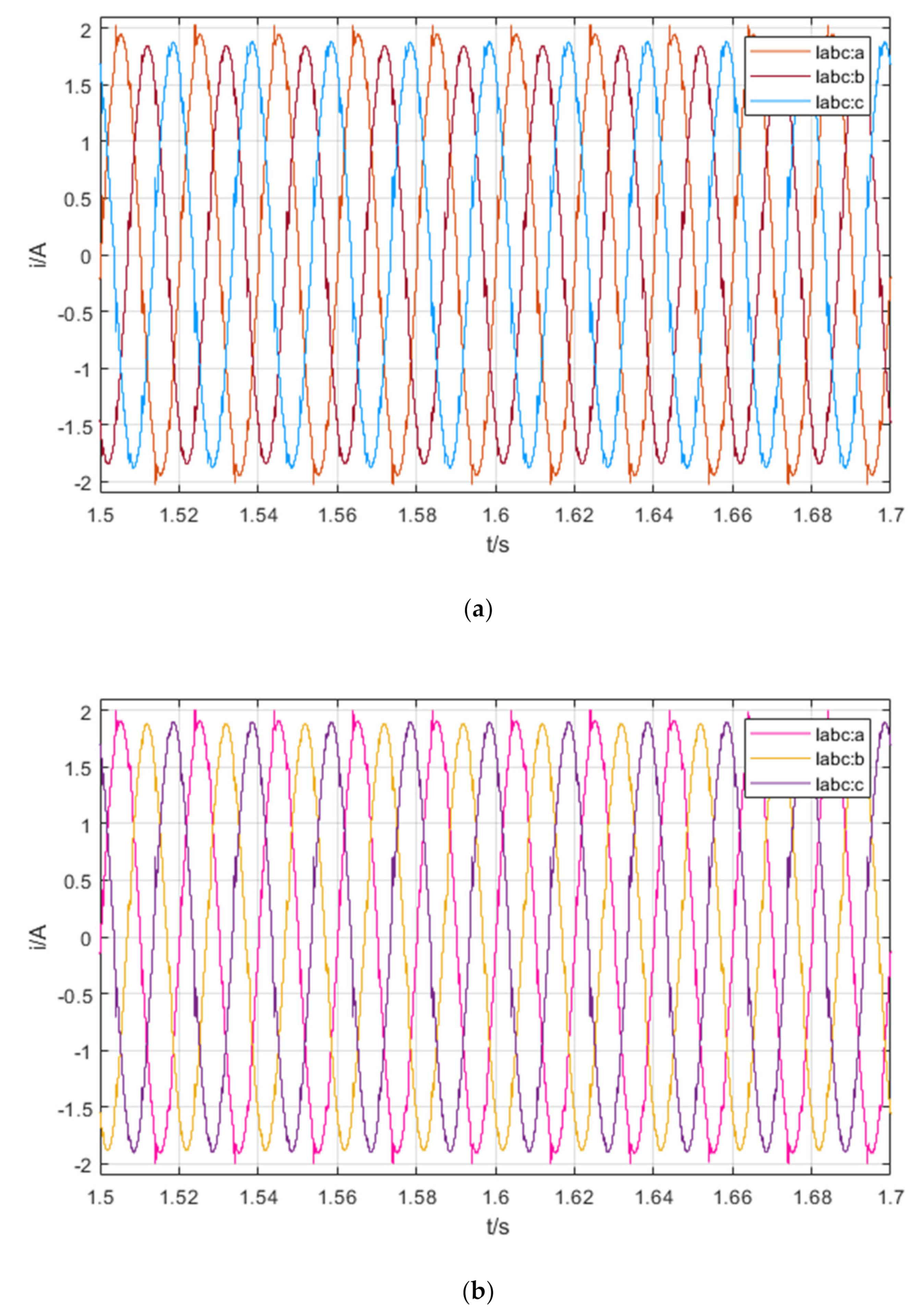
Figure 16a,b show the grid-side current waveform when the harmonic damping control coefficient
K is equal to 500 and 2000, respectively. By comparing the results in
Figure 16a,b, it can be learned that with the increase in
K, the filtration performance under the HIAF system is improved, which verifies the theoretical analysis in
Section 4.2. Specifically, the unbalanced three-phase grid-side currents are attenuated with the increase in
K. The increasing
K greatly reduces the influence of the load-side harmonic currents on the grid-side currents.
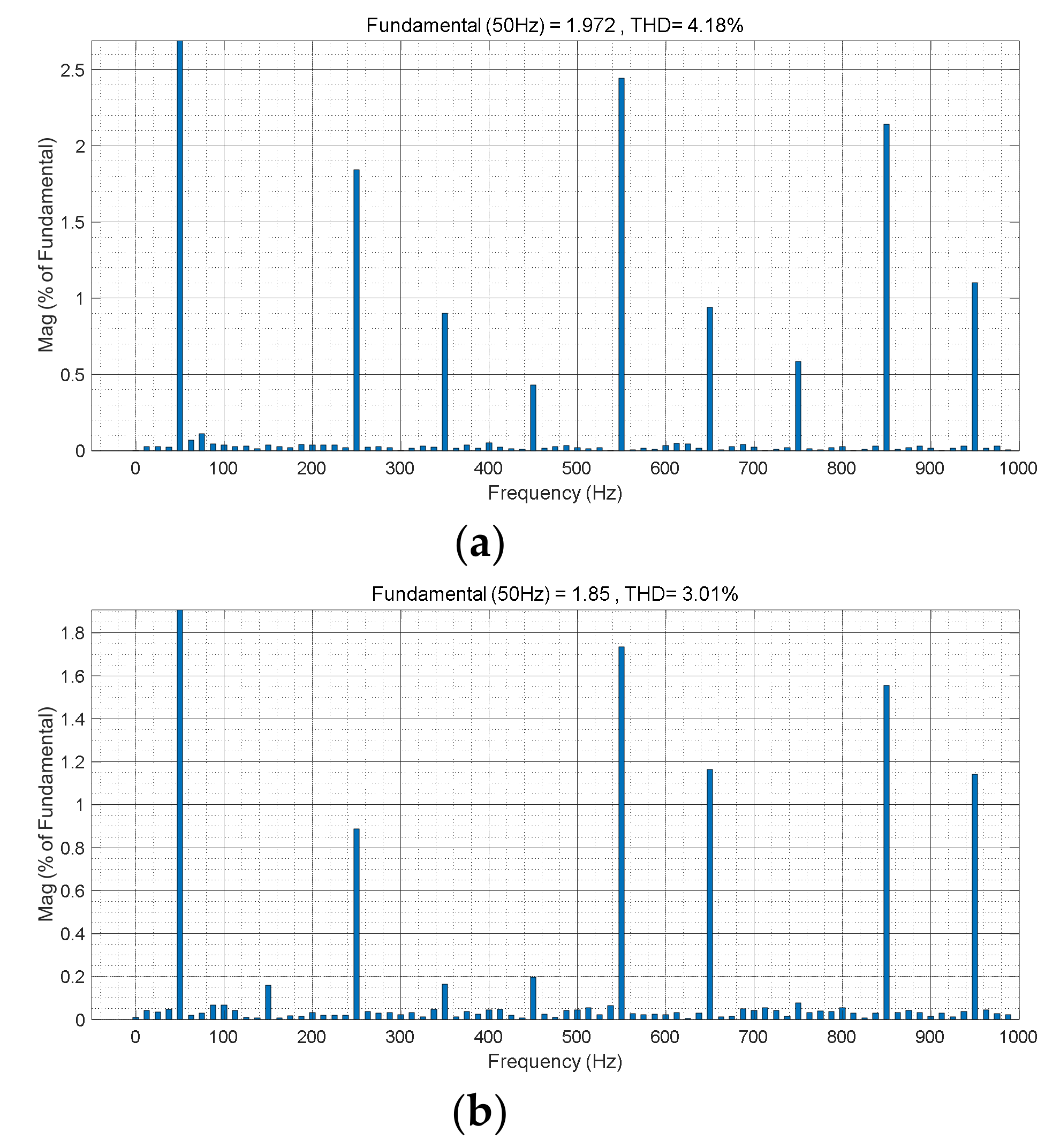
Figure 17a,b show that the current distortion rate of phase A of the grid-side current can also be decreased by increasing
K. Due to the control of VSI, the current contains almost no 3rd, 9th, and 15th harmonics.
6. Conclusions
In this paper, a novel HIAF system is proposed for a low-voltage distribution network. The proposed HIAF system is mainly composed of a Ddy transformer, fully tuned filtering branches, and VSI connected in series. Based on the equivalent circuit model and mathematical model, we derive the theoretical conditions of the harmonic suppression using the HIAF system. The application of HIAF in low-voltage distribution networks can reduce the voltage level of active inverters. Harmonic damping control can effectively inhibit the transmission of a harmonic current to the transformer’s grid side. The simulation analysis shows that the proposed HIAF system outperforms under both balanced and unbalanced loads. As for the 3rd harmonic caused by unbalanced nonlinear loads, the HIAF system can effectively suppress it without using a separate filtering branch.


