1. Introduction
Pilger mills are widely used for the production of seamless pipes of various sizes. Depending on the purpose of the pipe (oil industry, chemical industry, mechanical engineering, civil engineering, etc.), the quality requirements can vary significantly. Among the several successive rolling stages in pilger mills, the most critical for the production of high-quality pipes is the cold-rolling stage.
Cold-rolling is mainly used for pipes made of stainless and high-alloy steels, low-plastic metals and alloys, and pipes for critical purposes [
1,
2,
3]. Cold-rolling creates pipes that are accurate in geometric dimensions with high-quality inner and outer surfaces. For example, the HPT-250 mill (Chelyabinsk Pipe Rolling Plant, Chelyabinsk, Russia) rolls seamless pipes with an outer diameter of 57 to 250 mm and a wall thickness of 1.5 to 32 mm.
High-quality pipes are produced on batch mills (see
Figure 1) [
4,
5,
6]. The cold-rolling process is similar to the hot pilger rolling process. The reduction of the metal is carried out by work rolls, which, together with the work stand, make a reciprocating motion, while the rolls simultaneously perform a reciprocating and swinging motion. Interchangeable grooves with a stream of variable sections are fixed in the rolls. Rolling is carried out on a fixed conical mandrel.
The pipe-rolling units of the pilger mill have a complex and nonstandard movement of the executive instruments, a large unevenness of the load torque during one rolling cycle, and the need for the coordinated operation of the rolling tool and the auxiliary mechanisms.
When the rolls are in the extreme left position (the rear position of the rolling stand), the billet is fed into the stand. In the extreme right position of the rolls (the front position of the rolling stand), the pipe is rotated.
In the current version of the mill, the operation of auxiliary mechanisms is directly related to the operation of the main electric drive of the rolling stand using a mechanical transmission. This approach does not provide reliable synchronization of the sequence “turning/feeding of rolled products—rolling stage”. This leads to untimely pipe turning/feeding and, as a consequence, overloads in the mill operation and a decrease in the quality of rolled products.
The requirements for the quality of the rolled products are strict; for example, the maximum deviations in diameter on the HPT-250 mill are 0.3–1 mm, and for the pipe wall thickness they are 0.2–0.9 mm.
An increase in quality and productivity is possible by reducing the rolling speed, which is undesirable and, in some cases, unacceptable [
7,
8].
The existing methods of ensuring product quality and productivity in the literature are considered mostly from the standpoint of the current layout of equipment in pilger mills [
9,
10]. A careful study of the features of the operation and technical implementation of the electric drives of these mills, from the position of the tasks set, shows the need to ensure the separate but coordinated operation of auxiliary mechanisms and the main drive, and the ability to work out the resulting overloads without significantly affecting product quality.
This requires an in-depth preliminary analysis and an integrated solution. Given the increasing demand for seamless pipes, the increasing requirements for the quality of rolled products, and productivity [
11], a significant share of electricity consumption by pilger mills, and the physical wear and tear of electrical equipment, this scientific and technical problem is urgent.
The authors have practical experience in developing an electric drive for turning a cold-rolling mill of a larger range (HPT-450). The authors of [
12] draw attention to the sufficiently high rigidity of the system and the absence of the need to deal with vibration damping. The synthesis problem in this case was greatly simplified and reduced to the development of an electric drive system with the highest possible speed.
The ductility of pipes during rolling on the HPT-250 mill is more significant, which makes it possible to take into account possible fluctuations. As a result, to ensure the desired product quality and productivity, taking into account the existing limitations, it is necessary to develop an electric drive system with significantly better weight and dimensions.
In the current work, as an electromechanical converter for the electric drive of the pipe feed mechanism, an independent excitation synchronous reluctance motor (IESRM) is proposed, which, from the standpoint of reliability, operational, and technical and economic indicators, has a number of advantages [
12]: high specific torques in long-term operation; a control system that ensures the linearity of the motor torque characteristics, which effectively increases the linear current load by 20%; the simplicity of the control systems; IESRM energy losses relative to traditional engines are lower by 30–40%; less torque of inertia; a simple and reliable rotor design: no magnets and short-circuited winding; an electric drive control system with IESRM achieves a high overload capacity (3–5 times the rated torque).
2. Selection of a Mechanical Transducer According to the Criterion of Minimum Vibration
The presence of an elastic connection between the pipe workpiece (displaced from the mandrel) and actual electric feed drive necessitates the choice of a mechanical converter (reducer) with minimum system oscillation. Taking into account the results in [
12] using the frequency analysis of the system, the dependency of the root-mean-square torque on the gear ratio of the mechanical converter and the amplitude of the resonance maximum of the frequency response was obtained. In
Figure 2, the calculation results are presented in relative units, where the root-mean-square value of the torque of the existing technical solution is selected for the base value of the electric drive load.
The given dependency characterizes the degree of oscillation of transient processes. A decrease in the gear ratio of the gearbox leads to a weakening of the influence of the elastic link. As a result, the effect of the “second” mass on the operation of the entire system decreases. However, a significant change in the gain increases the static load on the drive (see
Figure 2, green limit plane).
The minimum values of the root-mean-square torque and, consequently, the power of the electromechanical converter are obtained when the kinetic energy of the working body and engine is equal. It should be noted that the amplitude of the resonant maximum of the frequency response in this case can be significant. In the article, the value of 10% is taken as the permissible value of the difference in the thickness of the rolled products [
13,
14,
15,
16], which can be achieved only with a strict limitation of the oscillation of the processes of the electric drive system at the level of 15% (see
Figure 2, red limit plane).
The result of ensuring the minimum oscillation of the system represents several permissible points; however, the root-mean-square torque exceeds the accepted base value, which will lead to an increase in the torque of inertia and the overall dimensions of the electromechanical converter. In this case, the authors consider it necessary to perform the procedure for optimizing the weight and dimensions of the electric motor.
3. Optimization of Weight and Size Parameters of an Electromechanical Converter
The synchronous reluctance electric drive of the independent excitation has a number of advantages: winding-free rotor design, simple overall design, and energy efficiency (no losses in the rotor), which ensure a high overload capacity. These strengths, taking into account the requirements for the operation of the mechanisms of the cold-rolling mill, were decisive in the design of the system.
This type of electromechanical converter has a windless design and significant longitudinal rotor stiffness, which allows the rotating part of the machine to have a high ratio of length to diameter, and, as a consequence, the machine has a significantly lower torque of inertia. A synchronous reluctance machine of independent excitation, as shown by the authors of [
12], can be manufactured with the overall dimensions of a typical induction motor. However, it is necessary to pay attention to a number of factors: the peculiarities of the magnetic flux flow, the size and location of the magnetically nonconductive rotor inserts, and the distribution of mechanical stresses. Therefore, it was decided to optimize the geometry of the machine and take the electromagnetic torque developed by the engine as the main criterion.
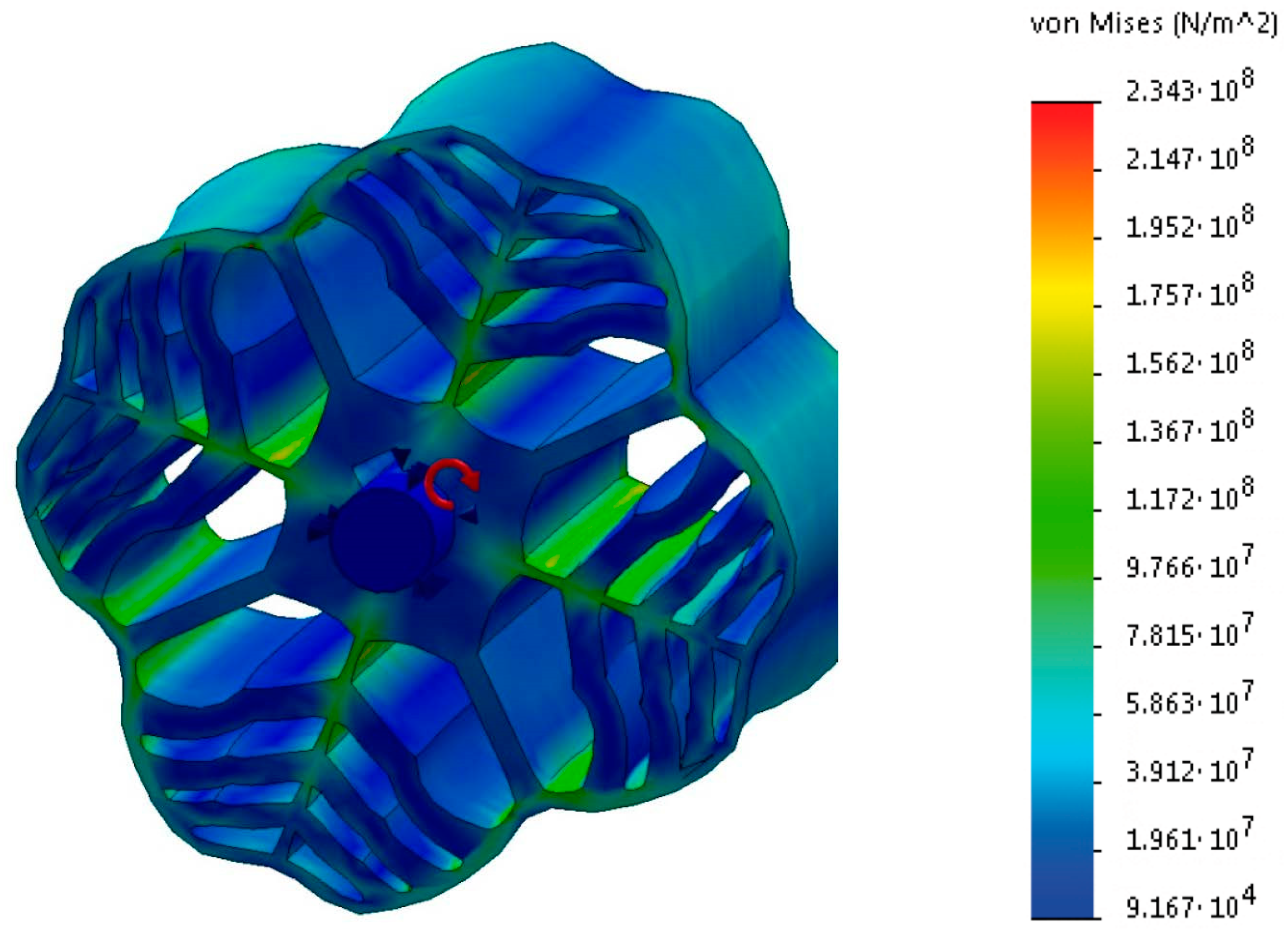
The task was reduced to finding the ratio of the inner diameter of the stator to the outer one, and the size of the rotor back, and the subsequent calculation of the mechanical stresses arising in the rotating part of the machine. In the course of the study, a static analysis of the mechanical properties of the object was carried out under the action of centrifugal forces (angular velocity ω = 120 rad/s) and under the action of a static torque (3.5T
r = 9200 Nm). The distribution pattern of mechanical stresses under the action of centrifugal forces is shown in
Figure 3.
Under centrifugal forces, mechanical stresses significantly exceed the specified yield point (σ = 235 MPa). The highest stress values arise in the back of the rotor, between the outer diameter and magnetically nonconductive inserts. The resultant forces give one more parameter to be taken into account in the optimization problem: the size of the rotor back.
The stress distribution pattern under torque is shown in
Figure 4. The analysis of the mechanical properties under the influence of the torque showed that the arising stresses are much less than the specified yield point and there is more than a two-fold margin.
The studies carried out allow us to conclude that, in this configuration, the rotor does not have sufficient mechanical strength. Taking the above into account, it was proposed that the minimum size of the rotor back for a given standard size of the machine be at least 4 cm and that a jumper be placed in the radial direction. An example of the distribution pattern of mechanical stresses under centrifugal forces is shown in
Figure 5.
The results show that, in the modified configuration, the rotor has sufficient mechanical strength, and the mechanical stresses under centrifugal forces will not exceed the yield strength of the material and the maximum value of elastic deformations.
The optimization of the weight and size of the IESRM was carried out numerically. However, in order to take into account the complex design of the magnetic system, the finite element method was used. The results of the optimization problem are presented by the dependency of the magnitude of the electromagnetic torque T on the ratio of the inner diameter of the stator Din to the outer diameter Dout and the size of the rotor back Srot.
The problem was solved by the Fletcher–Reeves gradient method, which is a modified descent method and characterized by fast convergence:
where
—a motor torque;
—size of the rotor back;
—the ratio of the inner diameter of the stator to the outer diameter.
The direction of the descent is calculated by calculating the gradient of the function T(Srot; D*). A new direction of descent is selected based on the resulting step of the decision vector. This step takes into account the previous one.
The calculation of the electromagnetic torque is carried out by the expression:
where
—magnetic induction;
—unit vector along the axis z;
—radius vector in the global cartesian coordinate system;
—surface normal.
The calculation algorithm was implemented with the software product Ansys Maxwell. The finite element method is used for electromagnetic calculations.
As the starting point of the calculation, the ratio D
in/D
out = 0.7 was taken. The value of this indicator is dictated by the design recommendations for asynchronous electrical machines with two pairs of poles. For an IESRM, the best geometry optimization indicators are observed at D
in/D
out = 0.6 at the minimum size of the rotor backrest (
Figure 6).
A further decrease in this indicator is impractical, since it does not lead to a significant change in the electromagnetic torque of the engine. However, taking into account the results of calculating mechanical stresses in the rotating part of an electric machine, the minimum allowable distance from the outer diameter of the rotor to the magnetically nonconductive insert cannot be less than 4 cm. Limitations on mechanical strength on the surface for optimizing the weight and dimensions are shown in gray (see
Figure 6).
The smaller Din/Dout exponent is easily explained. The distribution of the magnetic flux in an asynchronous machine is uniform along the entire length of the stator bore, and on the contrary, in a synchronous reactive machine, the flux lines are concentrated along the magnetically conductive parts of the rotor. This leads to a greater saturation of the stator back.
These results made it possible to develop a technical assignment for the design of an IESRM with nominal data: T = 2.6 kNm; I = 480 A; load angle θ = 13°; n = 1200 rpm; U = 660 V. The electric machine was manufactured at the SZSEM LLC enterprise.
In this work, attention was paid to the operating conditions of the electric drives of the feed-rotary group of the HPT-250 mill—significant overloads caused by the mismatch of the operation of the auxiliary mechanisms and the main drive. The dynamic and total loads reduced to the motor shaft are shown in
Table 1.
For the HPT-250 mill, the torque overloads can be 3.5 times higher than the rated load. Traditional asynchronous electric drives have a torque limit that does not exceed 3.5 times the rated value, while near this point, the stator current increases significantly and the electric drive can become unstable.
In IESRMs, the control system provides simultaneous control of the excitation and armature channels as a function of the load, thereby achieving a linear torque characteristic in the zone of significant overloads (3–5 times the nominal value). The use of a multiphase semiconductor converter makes it possible to independently control each phase of the stator winding; however, the synthesis of the power circuit diagram has its own characteristics.
4. Synthesis of Power Circuits
Until recently, it was believed that multilevel power circuits are most efficiently used for high-voltage electrical complexes (above 1 kV) [
17,
18]. Progress in the development of the elemental base of semiconductor technology made it possible to revise this and apply multilevel structures for low-voltage power supply circuits (up to 1 kV). Such solutions have a number of advantages. First, the actual operation of electrical equipment is simplified and, as a result, the requirements for servicing are reduced. Secondly, when working with reduced voltage, it becomes possible to increase the carrier frequency, resulting in a better form of the phase current. Finally, the use of both amplitude and frequency modulation leads to a decrease in losses in the semiconductor converters, which is important for objects with large installed power.
We start solving the multicriteria problem of optimizing the power circuit circuits by analyzing the costs of semiconductor converters [
19,
20,
21]. For this purpose, a statistical analysis of the data available in open sources was performed. The regression dependencies of the unit cost of electrical converters on the current load were obtained for well-known and proven manufacturers (
Figure 7).
With an increase in the power of semiconductor converters, the specific cost (per ampere) decreases because at low currents a significant share in the total cost of the converter is made by the microprocessor control system. In the high-power range, the share of the cost of digital signal processors and software is significantly lower compared to power semiconductor switches.
The best indicators for optimizing the weight and dimensions of the electric drive system can be achieved only when taking into account the joint operation of a semiconductor converter and an electric machine. In connection with this criterion for optimizing the power circuit diagram, the following indicator was chosen:
where,
is the component that takes into account the weight and size of the system “Frequency converter—electrical machine” depending on
y, while variable loads for excitation, armature and resulting flux (
) [
22], and the motor parameters (
—the ratio of the inner diameter of the stator D
in to the outer diameter D
out,
—pole pitch, T = 2.6 kNm, I = 480 A, n = 1200 rpm, U = 660 V [
23]) were taken as constant. The optimization parameter was the value of the phases of the frequency converter and the electric machine
f, in this case, the following restrictions were imposed on
f ;
T is the motor torque at the rated current.
At the next stage, it was assumed that in a polyphase system, the current of one branch is inversely proportional to the number of phases. Using a regression analysis (
Figure 7), the dependency of the unit cost of the electrical system was represented by the polynomial:
Coefficients
,
, …,
depend on the unit cost of semiconductor frequency converters and are obtained taking into account the results of the analysis (
Figure 7). At the next stage, they were refined for multilevel circuits, where I
r is the coordinate that is proportional to the rated current and varies as a function of the quantity phases of the power circuit.
The problem under consideration is more convenient to solve by numerical methods, and for a given order of the polynomial, the method of one-dimensional search for the extremum of a function was adopted.
Figure 8 shows a surface reflecting the dependency of the index
on the number of phases and the nominal torque of the working mechanism. For a fixed speed, the system power is proportional to the rated torque T.
Figure 8 shows that for objects of low power, the lowest costs for a semiconductor frequency converter are achieved for a power circuit with three phases, and this is consistent with the existing data [
24,
25,
26]. If the installed power of the electrical facility increases significantly, the extremum of the function (minimum) is achieved with a larger number of phases. At a nominal torque T
r = 6000 Nm and rated power P
r = 1000 kW, the minimum cost of a semiconductor frequency converter is when the power circuit is made with seven phases. This is explained by the peculiarities of the construction of power circuit diagrams using transistor modules for a high installed power: the three-phase version provides for the parallel connection of transistor valves. Such a configuration of power circuits requires taking into account the asymmetric loading of parallel-connected modules. As a result, the total rated current is reduced by 5–10%. If we increase the number of phases, then this will avoid the parallel connection of power transistor modules, and, consequently, reduce the cost of the power converter unit.
The AE curve (
Figure 8) shows the dependency of the
index on the installed power for a standard asynchronous electric drive. This curve lies below the surface and this is because the
index takes into account not only the cost of a semiconductor converter but also the cost of an electrical machine.
When synthesizing power circuits, it is useful to take into account system reliability. One way to increase them is associated with the overestimation of the installed capacity of the power plant (motor and semiconductor converter), but in this case, the size and cost indicators are significantly overestimated. A second way is to increase the number of phases and perform galvanic isolation between the phase windings of the motor. This solution is acceptable for special electrical machines of metallurgical installations. In such cases, the failure of one of the phases of the electric machine does not lead to the electric drive system stopping, since the object remains operational with a slight decrease in the permissible rated load.
Figure 9 shows the dependency of the permissible torque on the total number of phases of the power circuit diagram
f and on the number of failed phases
f’. The results showed that if one of the phases fails for a circuit with a phase configuration from the condition
f > 6, it leads to a slight decrease in the permissible torque. For a power circuit with six phases, this decrease does not exceed 5%, and for 12 phases—2%. The presented dependency also allows us to quantify the reliability of a polyphase circuit. If circuits with six phases are used, then the probability of failure-free operation will be 0.92, and in a 12-phase configuration, this figure reaches 0.95.
New approaches to the configuration of power circuits require a revision of the principles for determining the optimal number of phases and the structure of semiconductor converters. Since modern high-power frequency converters are made in the form of modules, and each element of a semiconductor device (inverter unit, rectifier, filter module) includes several nodes connected in parallel, it is advisable to increase the traditional number of phases. This approach allows a reduction in the installed capacity and cost and an increase in the system reliability indicators.
The rejection of two-level circuits and the transition to multilevel configurations of power circuits for voltage levels up to 1 kV makes it possible to implement more complex algorithms for generating the output voltage, both in the pulse-width and amplitude modulation modes. As shown in [
17,
18,
27,
28,
29,
30], electrical losses in the system are reduced by about 1.5%.
It is theoretically shown and experimentally confirmed that due to the development of the modern element base, the use of three-level frequency converters for voltage levels up to 1 kV is economically justified. It was found that in addition to the existing advantages of such a scheme (reducing switching losses and overvoltage on the phase winding), it is possible to further increase the efficiency of the frequency converter due to a greater number of degrees of freedom in the transition to multiphase circuits.
5. Discussion and Results
The developed electric drive was introduced to the Chelyabinsk Pipe-Rolling Plant at the end of 2019 on the feed and turning mechanisms of the pipe of the HPT-250 cold-rolling mill. The power circuit diagrams of semiconductor converters, implemented according to a six-phase three-level design, were assembled at “Privodnaya Tekhnika” on the basis of the MT2000 MOMENTUM series (see
Table 2).
Multiphase synchronous reluctance machines of the SRMTD250-400MB4 type were designed and implemented according to the proposed methods on the basis of the Snezhinsk plant of special electrical machines (see
Table 3).
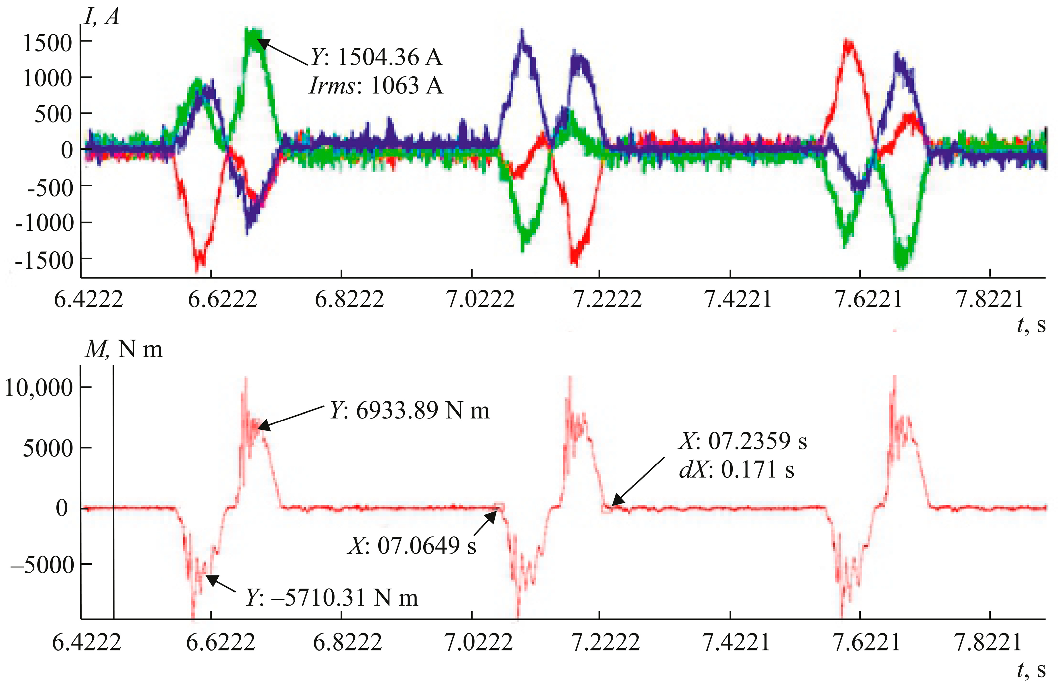
Figure 10 shows the oscillograms of the processes that were recorded by a Fluke 192 V digital instrument. The oscillograms show that the time constant of the transient process in the torque control loop did not exceed 0.001 s, and the uniform frequency bandwidth was at least ω
s = 1000 rad/s. Comparing the oscillograms of current and torque shows that the relationship between the electromagnetic torque and current was linear, even in the zone of significant overloads. Thus, the overall speed of the electric drive of the swing mechanism was increased about three-fold, and the overall productivity of the mill was improved by about 10–15%.
After setting up and launching the facility, measurements of the energy indicators of the system were performed by recording a power consumption graph. It was found that it was possible to reduce the losses in the semiconductor converter by about 1%. This increase in efficiency is primarily due to the use of a three-level frequency converter.
6. Conclusions
The result of the work performed was a multicomponent system that meets modern standards and requirements, ensuring high efficiency and product quality. The experimental part of the work made it possible to fully evaluate and show the high speed of the system, lower electrical losses, required overload capacity, and coordinated operation of auxiliary mechanisms and the main drive of the HPT-250 cold-rolling mill.


