Article

The Proposition of an Automated Honing Cell with Advanced Monitoring

Department of Manufacturing and Production Engineering, Gdańsk University of Technology, 80-233 Gdańsk, Poland
*
Author to whom correspondence should be addressed.
Machines 2020, 8(4), 70; https://doi.org/10.3390/machines8040070
Submission received: 3 September 2020 / Revised: 19 October 2020 / Accepted: 22 October 2020 / Published: 28 October 2020

Abstract

:
Honing of holes allows for small shape deviation and a low value of a roughness profile parameter, e.g., Ra parameter. The honing process heats the workpiece and raises its temperature. The increase in temperature causes thermal deformations of the honed holes. The article proposes the construction of a honing cell, containing in addition to CNC honing machine: thermographic camera, sound intensity meter, and software for collecting and analyzing data received during machining. It was proposed that the level of sound intensity obtained during honing could be monitored continuously and that the images from a thermographic camera could be analyzed on-line. These analyses would be aimed at supervising honing along with the on-line correction of machining parameters. In addition to the oil cooler, the machining cell may have an automatic selection of the grain trajectory shape, with specified value of the radii of curvature of the abrasive grain trajectories, according to the wall thickness of the honed workpiece, which will result in reducing the temperature generated during honing. Automated honing cell can mostly increase honing process efficiency. Simulations in FlexSim showed the possibility of increasing the efficiency of the honing process more than 20 times.

1. Introduction

The honing process heats the workpiece and raises its temperature. Specialist literature dealing with the honing process of cylindrical surfaces draws attention to the issue of the temperature increase during machining [1,2,3,4,5,6,7,8,9,10,11], which causes the thermal deformation of the honed hole. The temperature increase is also a very important issue during the honing process of flat surfaces by grinding with lapping kinematics as shown in [12]. Another interesting issue, in addition to the coexisting issue, i.e., surface texturing [13], is the use of new honing methods [14,15,16,17] and honing equipment used during machining [18,19] to improve the quality of the holes obtained [20,21,22,23,24].
The process of honing is influenced by the selection of proper machining parameters [1,25,26,27,28,29,30], which directly affects the obtained cylindricity deviations of the honed holes [9,10,31,32,33,34,35]. Much attention in the literature has also been devoted to examining the possibility of creating a new honing equipment and machines [18] as well as machining strategy, during which a different shape of oil channels cross-hatch could be obtained [12,36,37,38,39,40,41,42,43,44,45,46] which influences the further development of honing methods [47,48,49,50,51,52].
Irene Buj-Corral [2] described the methodology of selecting the appropriate density of the abrasive whetstone based on the analysis of the acoustic signal recorded in honing process and checked that roughness of honed cylinders increases mainly with abrasive grain size, followed by honing head pressure. She researched that tangential speed influences roughness slightly [53]. Similarly, Chavan [38] describes the effect of the pressure of the abrasive whetstone and the honing speed on the obtained roughness profile parameters. Deepak [27] dealt with in detail the influence of honing parameters on the obtained parameters of the roughness profile of honed surface. He stated that the rotational speed of the head had the greatest influence on the Rz, Rk, and Rvk parameters, while the linear speed of the jump had the greatest influence on the Rpk parameter. Barylski [1] indicates that the selection of parameters affects the size of the honed material and affects the amount of temperature generated in the workpiece.
The latest literature describes the use of the neural network method to supervise the honing process [54], but the analysis of parameters leads to obtaining the desired roughness profile parameters. In this article, it is proposed that the neural network completely diagnose the process of honing, including the analysis of the sound signal obtained during honing and the analysis of thermograms recorded during honing, which is a novelty in proposing the direction of the honing process and its automation.

2. Kinematics of Honing Process

Goeldel [41,55] proposed to use new shapes of grain paths for honing of cylindrical holes. Bujukli [56] describes the effect of the honing head stroke length on the improvement of the cylindrical shape deviation of the honed hole.
Figure 1 shows the cross-section of the honing head and the speeds occurring in the machining system: Vax—axial linear speed of the honing head [m/min], Vaz—peripheral speed of the honing head [m/min], Vexp—infeed speed of abrasive whetstone [µm/min].
The honing head has a vision system (item 6), which records the real-time image of the honed surface, introducing data to the neural network that verifies the number of oil channels produced in such a way that the continuity for the flowing oil is broken. The gauge of the pressure force and the diameter of the machined hole (item 4) and the temperature gauge (item 5) enable the supervision of the honing process in real time.
The basic formulas that define the honing kinematics (Figure 1) are:
- resultant cutting speed [m/min]
V c = V a x 2 + V a z 2
- linear speed of the head in reciprocating motion [m/min]
V a x = 2 L n a x
where: L is the length of the head stroke in the axial direction, in reciprocating motion [m]; nαx is the head stroke frequency in reciprocating motion [1/min]; Vaz is the peripheral speed of the head [m/min]
V a z = π d n 1000
where: n is the head rotation speed [min−1]; d is the diameter of the honed hole [mm];
And
t g α = V a x V a z
where: α is the honing angle [°].
The honing angle is a parameter influencing the oil consumption and the amount of toxic compounds emitted to the environment during the operation of internal combustion engines [57]. It also affects the coefficient of friction of the piston rings against the cylinder surface [38,42,58,59], which has a direct impact on engine power losses.
The honing angle depends on the mutual relation of the rotational speed and the speed of the axial linear stroke of the head. A higher value of the rotational speed with a lower value of the honing head stroke speed makes the angle closer to the horizontal direction, a lower value of the rotational speed with a lower value of the head stroke speed makes the angle closer to the vertical direction.
Figure 2 shows an exemplary trajectory of the abrasive grain (item 1) obtained during honing on the developed surface of the machined hole (item 2). The advantage of the honing cell is the automatic selection of the shape of the abrasive grain trajectory, with different values of the grain trajectory curvature, which directly affects the amount of temperature generated in the workpiece.
There are a many combinations possible in the honing process of oil channel angle. This diversity is presented in Table 1. Various honing researchers and different engine manufacturers suggest the use of different honing angles, but this article proposes the use of honing with variable kinematics, which enables the creation of a scratch grid in the form of curvilinear oil channels.
Honing with traditional kinematics is carried out without a change in the machining parameters. Figure 3 shows traditional honing process, where rotational speed of honing had has a constant value during process. This honing method allows to create cross-hatch shape of abrasive grain trajectories. The rotational speed of the honing head at the beginning of the cycle increases from zero to a constant value (Figure 3a), the feed value increases from zero to a constant value (Figure 3b). In honing with constant kinematics, the stroke length increases linearly (Figure 3c), while the grain path length increases according to the curve shown in Figure 3d.
Honing with variable kinematics is carried out with a change in the machining parameters. Figure 4 shows non-traditional honing process, where rotational speed of honing had has a different rotation speed in one single cycle of honing process. This honing method allows to create different shape of abrasive grain trajectories. The rotational speed of the honing head at the beginning of the cycle increases from zero and can still increase or decrease in turn (Figure 4a), the feed value increases from zero and can increase and decrease in turn, etc., the return of the speed vector can change to the opposite in any way (Figure 4b). In honing with variable kinematics, the stroke length increases not linearly but curvilinear and according to the rotational speed and stroke speed value (Figure 4c), while the grain path length increases according to the curve shown in Figure 4d.
Table 1 shows the honing angles that are discussed in the specialist literature.
Because of the disordered distribution of the grain in the abrasive stone, the grain fracture planes are at any angle to the grain direction, determined by the vector of the resultant honing speed Vc. During honing, the direction of the forces acting on the grain changes. Some of the grains are too weak in a given plane to transfer cutting forces, so that new cutting edges are constantly created during the honing process. Changing the direction of grain work also prevents the deposition of the processed material particles on the grain working surfaces; because of this phenomenon the change of the direction of the velocity vector Vc, i.e., variable honing kinematics, is an important parameter influencing the course of the process [5,6,7,8] and reduces the friction coefficient in the piston-cylinder assembly [80,82,84,85]. The value of normal acceleration an is responsible for the change of the vector Vc direction and the trajectory curvature.

3. Methods

The article proposes the construction of a honing cell, containing in addition to CNC honing machine: thermographic camera, sound intensity meter, and software for collecting and analyzing data received during machining. It was verified that the main factor hindering the serial honing treatment is the deformation of the shape of the honed hole, caused by the heating of the workpiece due to the friction of the abrasive stone against the honed surface, which also causes a change in the diameter of the hole. The prevention of this phenomenon consists in controlling the temperature to which the honed workpiece is heated during machining, and in carrying out the treatment in such a way that the amount of temperature increase is reduced due to the selection of proper honing parameters, depending on the shape and CCR (the curve curvature radius) of the abrasive grain trajectories [5].
Honing cell principle of operation: 1—numerical simulation of deformations, stresses, and heat flow, 2—programming of honing head movements with the selection of the appropriate shape of the abrasive grain path adjusted to the thickness of the section or sections of the honed workpieces, 3—supervising of honing during the process, measuring of diameter and cylindricity of honed hole, measuring of sound signal, 4—correcting of actual machining parameters.

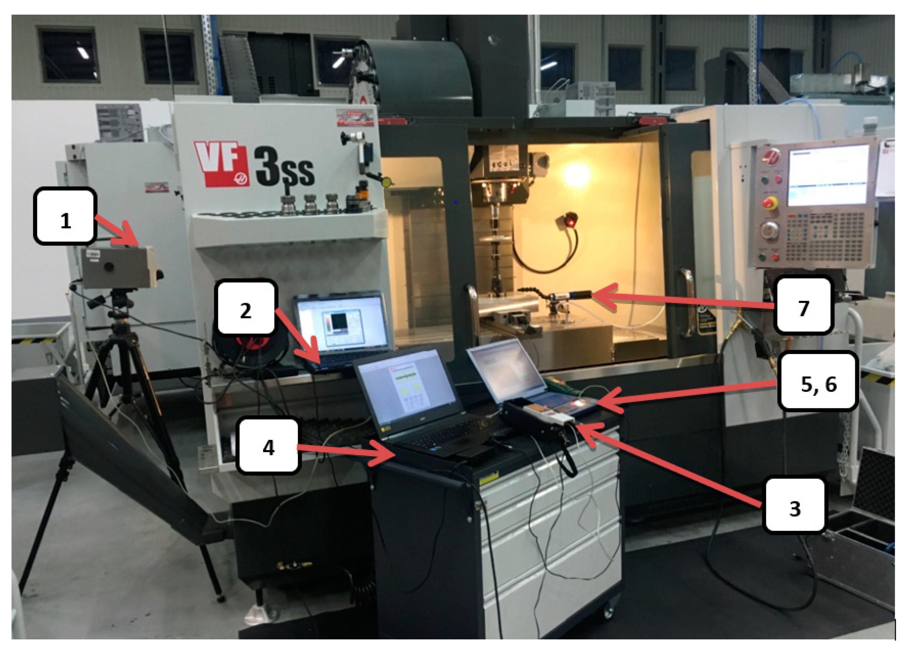
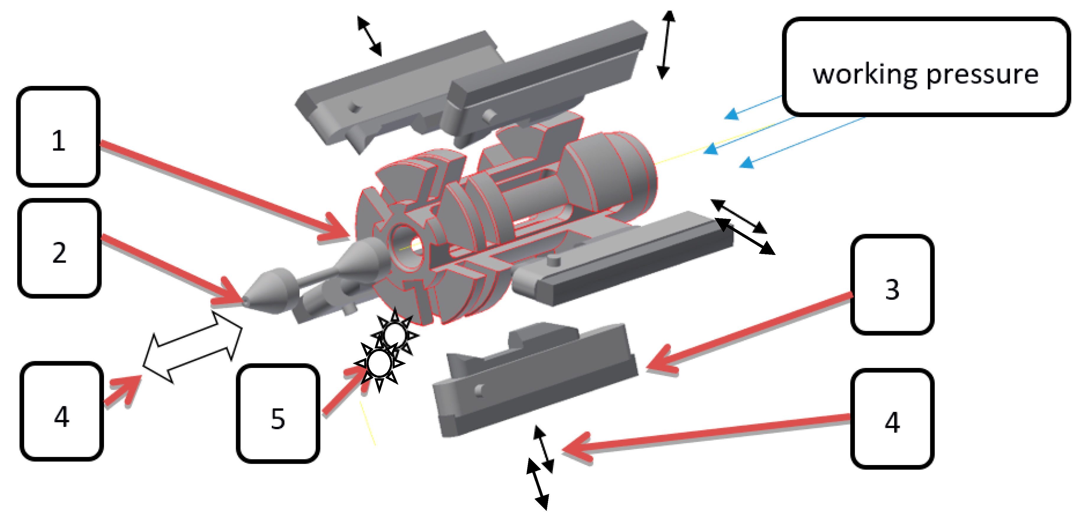
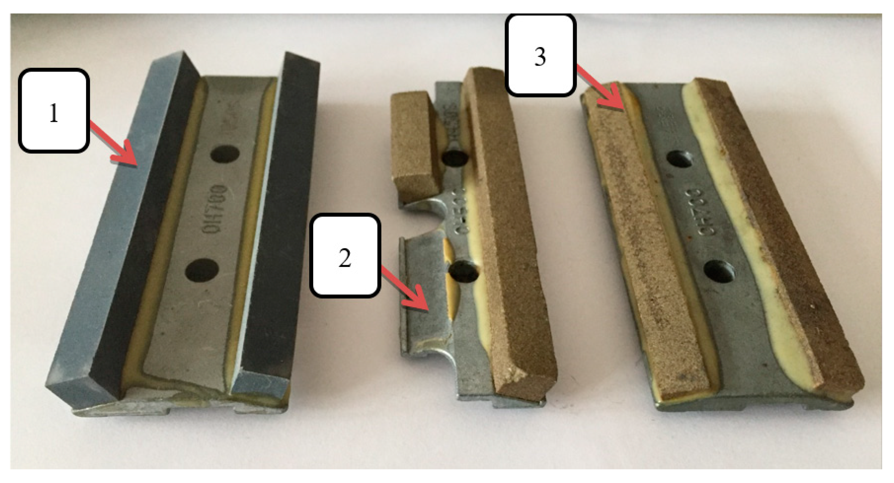
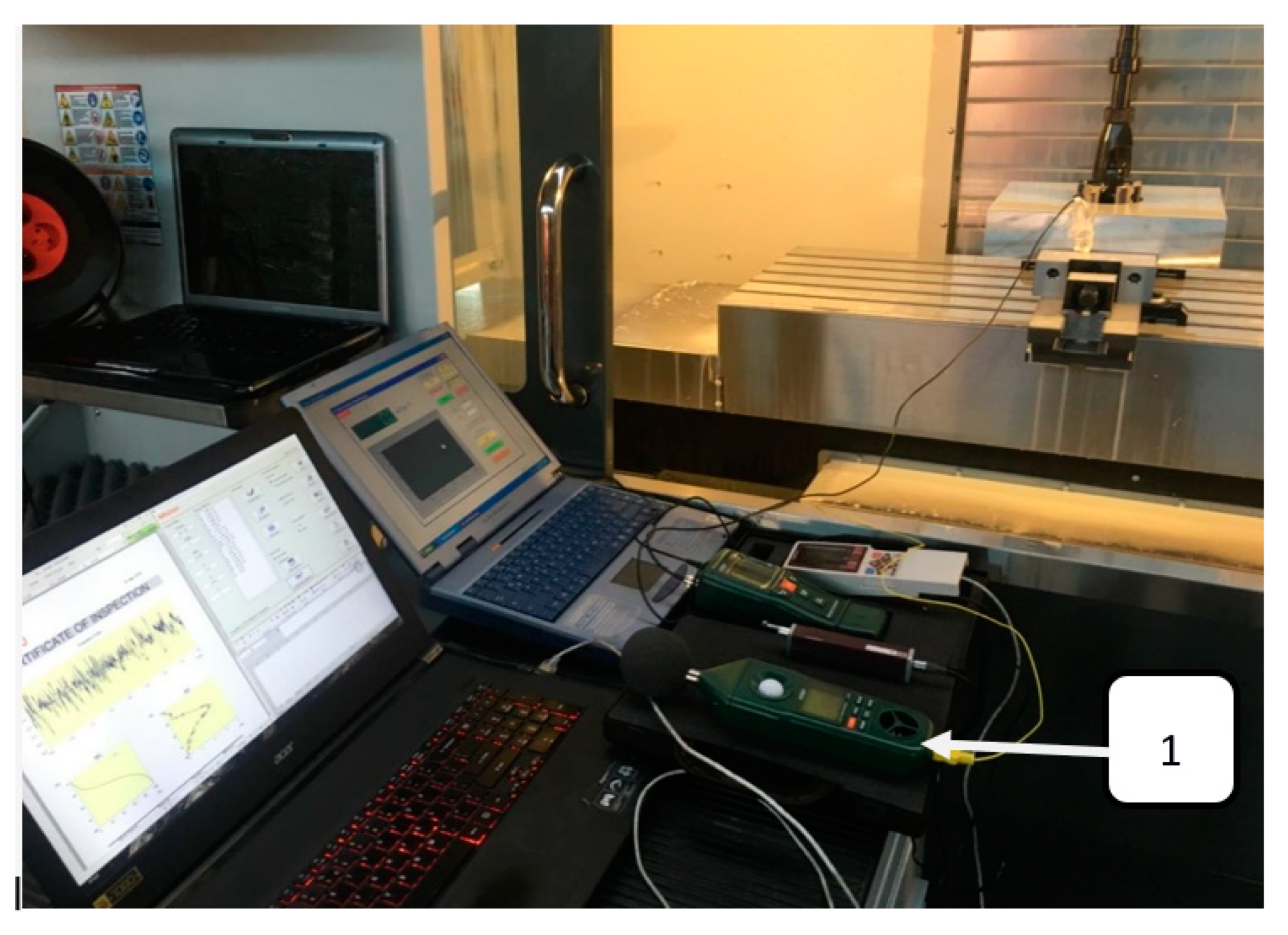
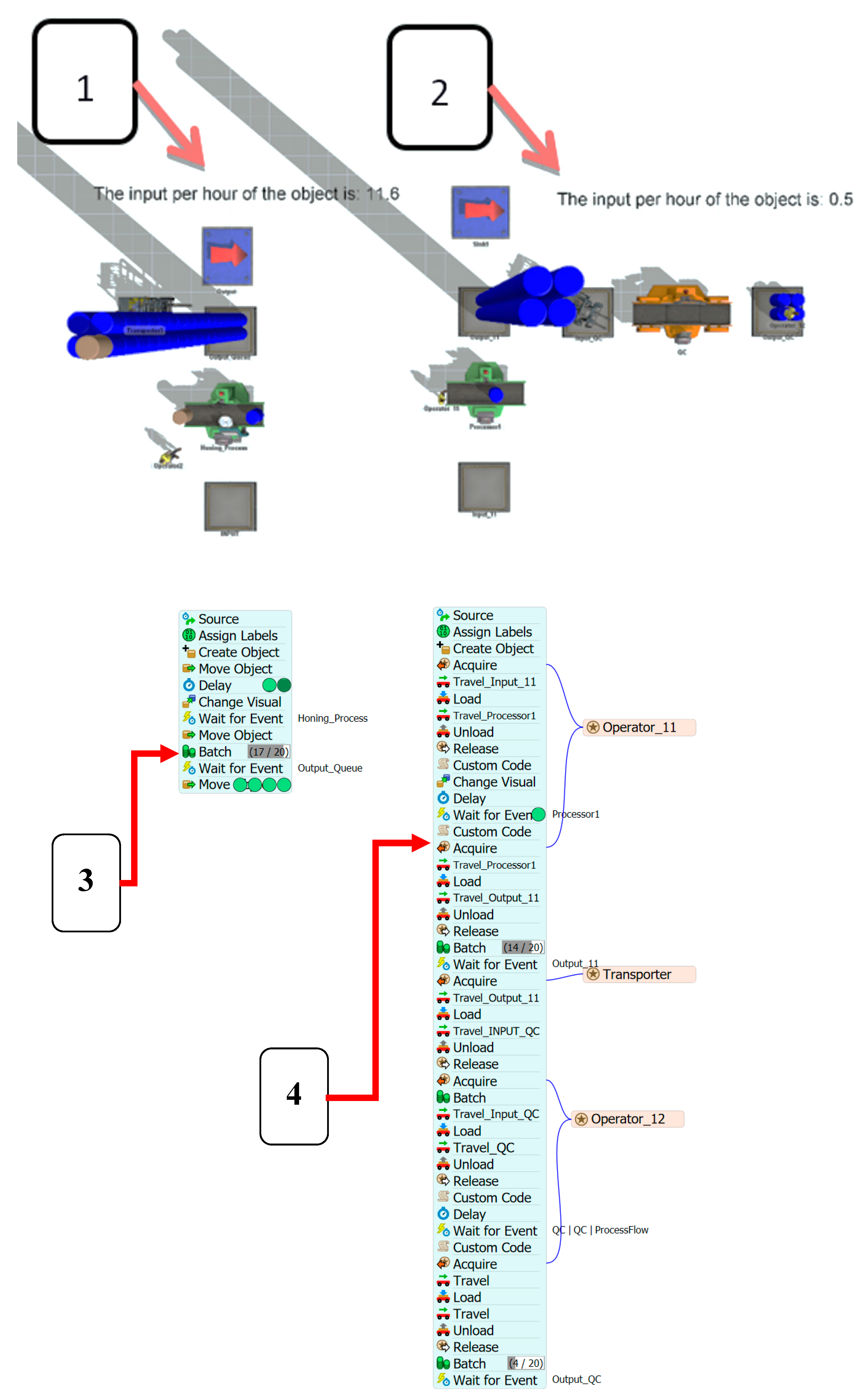
3.1. The Equipment of the Honing Cell

Figure 5 shows a CNC vertical milling center equipped with the honing instrumentation, a thermographic camera, surface roughness measure gauge, and sound intensity meter. Each of the three shown laptops analyzed different signals and their output values obtained during the honing process.
The key issue of the proposed automated honing cell is to be able to supervise the honing process by analyzing the audio signal and by analyzing the images obtained from the thermographic camera during the process. The task of supervision of honing process should be to generate abrasive grain paths with different shape of grain trajectories and with different radii of curvature, depending on the data obtained from the analysis of the acoustic signal and from the analysis of the thermogram of the workpiece.

3.2. Numerical Simulations of Honing Process

The honing cell should verify the influence of honing parameters on the size of the temperature increase, which is related to thermal deformation of the honed hole. The measurement should be carried out before machining, by performing a numerical simulation of honing.
Figure 6 shows the image recorded during the numerical simulation, showing the heat flux flow through the honed cylinder liner. The occurrence of different values of heat flux is clearly noticeable, depending on the thickness of the section of honed workpiece. The differences affect the non-uniform cylindrical deformation, more information is included in [5,6,7,8]. The simulation will provide information about the size of deformation for various possible variants of machining parameters, e.g., the amount of pressure of the abrasive whetstone on the workpiece.
The different temperature value of the honed workpieces causes the occurrence of different values of thermal stress in different places of the workpiece and affects the deformation of the cylinder shape, which is an undesirable phenomenon.
The honing cell should verify the influence of honing parameters on the amount of stresses and deformations occurring during honing in the workpiece. The measurement should be carried out before machining, by performing a numerical simulation of honing (Figure 7).

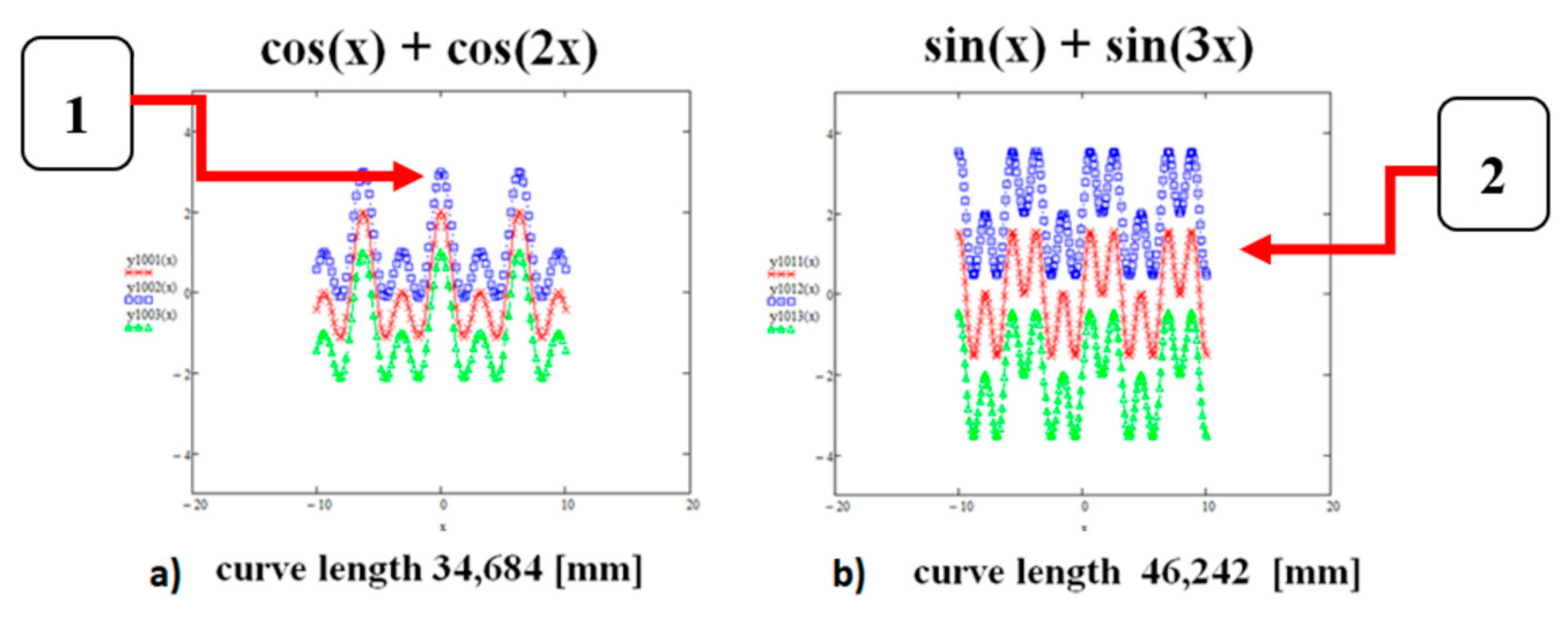
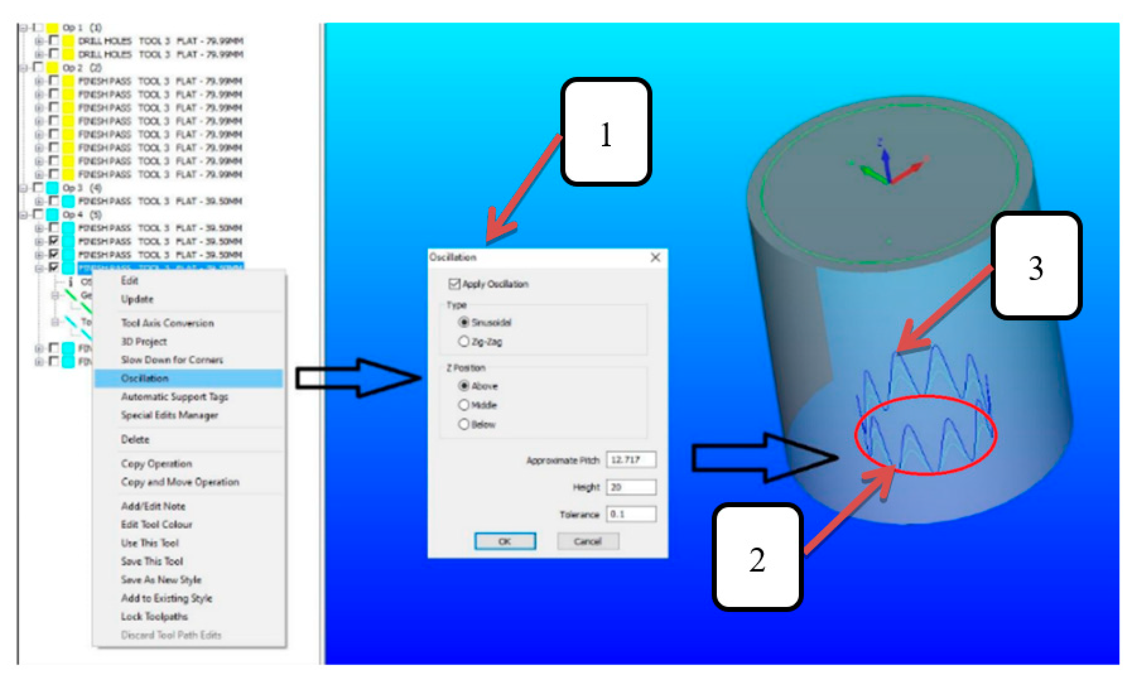
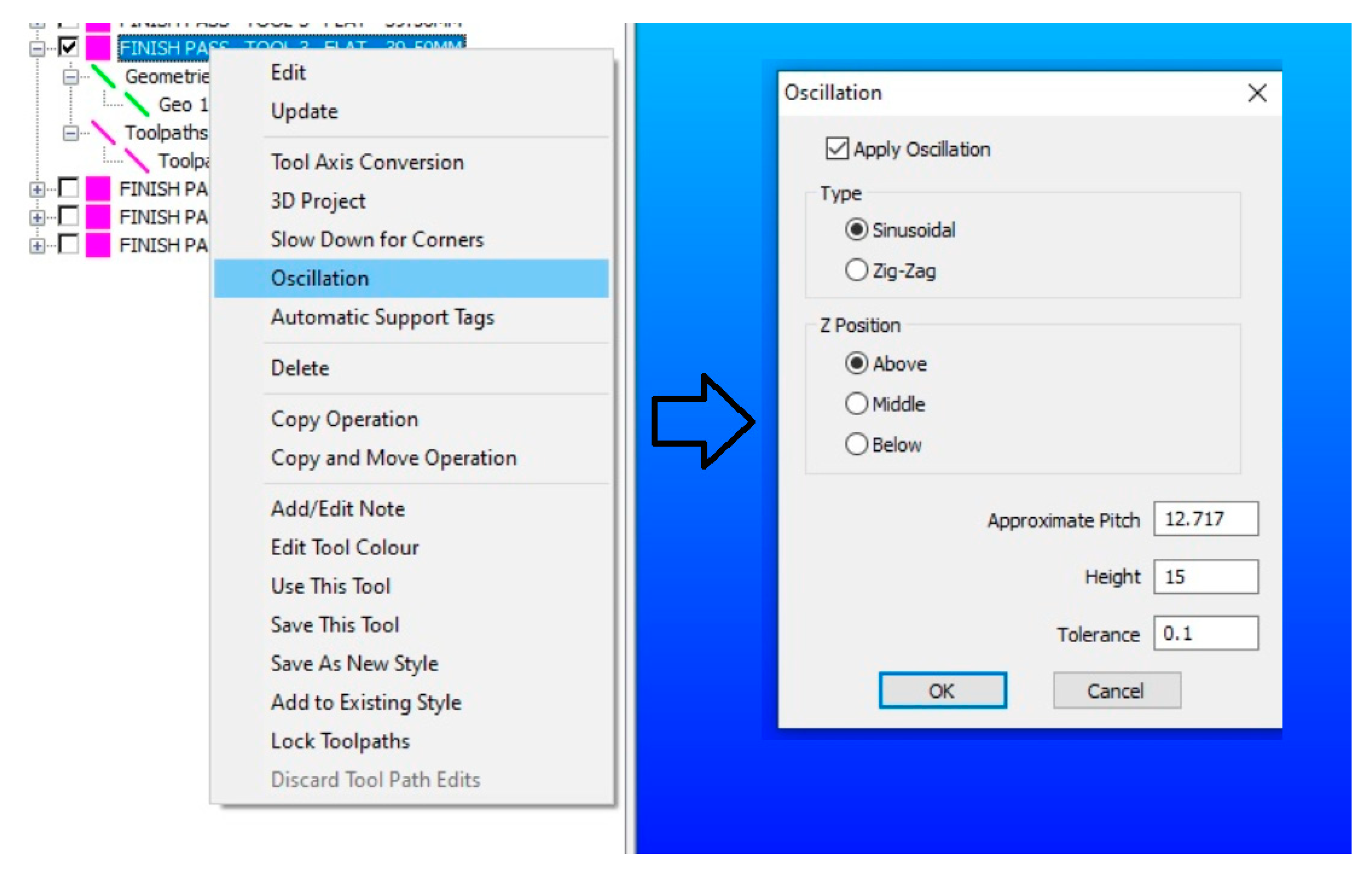
3.3. Programming of the Grain Trajectories in Non-Conventional Way

It was verified in [5] that the shape of the abrasive grain trajectories obtained in the honing process influenced the size of the temperature rise in the honed workpieces. In addition, abrasive grain trajectories can be generated using mathematical functions such as sin(x), cos(x) etc., which would allow the creation of a path of any shape, also curves with different radii of curvature.
A very interesting issue is the problem of programming the path of the abrasive grain, different one than the traditional path resultant from the rotational and linear speeds of the honing head, which is so far used in most honing machines manufactured by leading manufacturers. In the proposed approach, a curvilinear path can be selected and generated depending on the cross-sections of the honed workpiece. It is defined in the form of a mathematical formula that defines a curvilinear path of various shapes with variable shape parameters (radius of curvature, amplitude size, frequency of change of direction). This kind of non-conventional programming can be realized in the CAD/CAM system, and previously planned in CCR (curve curvature radius) module.
Figure 2 shows the window view from the CAD/CAM Alphacam software, where it is possible to define a curvilinear path by adding a circular vibration to the path of varying magnitude and frequency of change of abrasive grain move direction.
Changing the shape of the abrasive grain path from a circular path to a sinusoidal path. Most basic form of sine wave describing the time function t is:
y = A sin(ωt + f)
where: A—amplitude, ω—pulsation in radians per second (closely related to the frequency in hertz), f—phase shift (if the phase is different from zero, the function graph looks shifted in time by 0 s).
The curves describing the trajectory of the abrasive grain may have various shapes, characterized by a different curvature of the grain trajectory [5]. The grain trajectory may take any shape, while performing which the honing head may more or less frequently change the direction of the axial movement (Figure 8). The quality of the hole made depends on the accuracy of the honing head movement [89,90].
Figure 9 shows the modification of the cylindrical path, which consists in changing the shape into a sinusoidal shape.
Figure 10 shows how to modify the shape of the machining path (item 2 from Figure 9) to a zig-zag shape path or a sinusoidal path (item 3 from Figure 9).

3.4. Setting of Honing Parameters

Automated honing cell should automatically setup the needing abrasive grain trajectories shape, as shown on Figure 9. Construction of honing head should allow for two-way steering of direction of abrasive whetstone and honing head movement (Figure 11) and should have possibilities to receive a machined surface images during process.
An important task is to use appropriate honing parameters that influence the course of the process. Incorrect honing parameters result in an excessive temperature increase and may cause the whetstone wear out in a very short time. Figure 12 shows the whetstone: 1—new, 2—after machining with incorrect pressure at the beginning of honing process, 3—worn out in a very short time.
It is advantageous to set machining parameters influencing uniform wear of the machining tool.

3.5. Supervision of Honing During Process

A very important issue for the automatic honing cell, in addition to the selection of machining parameters after the initial numerical simulation of the honing process, is to verify, supervise, and correct the obtained machining results in real time of honing process.

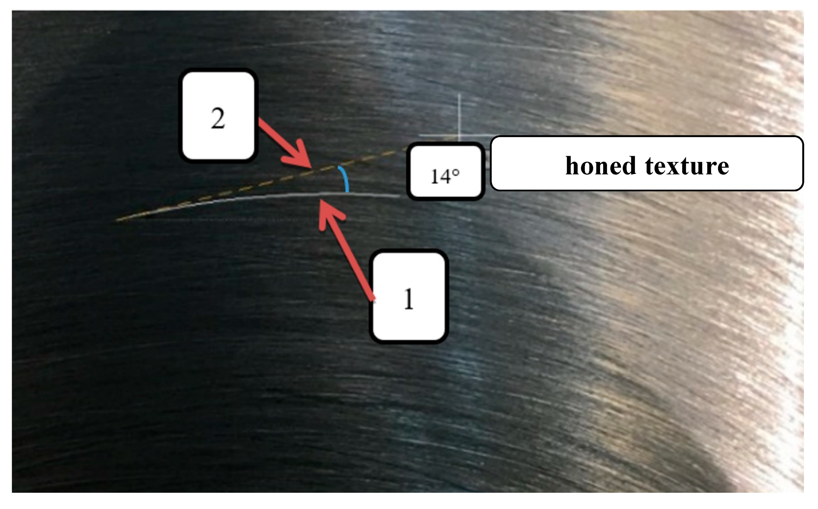
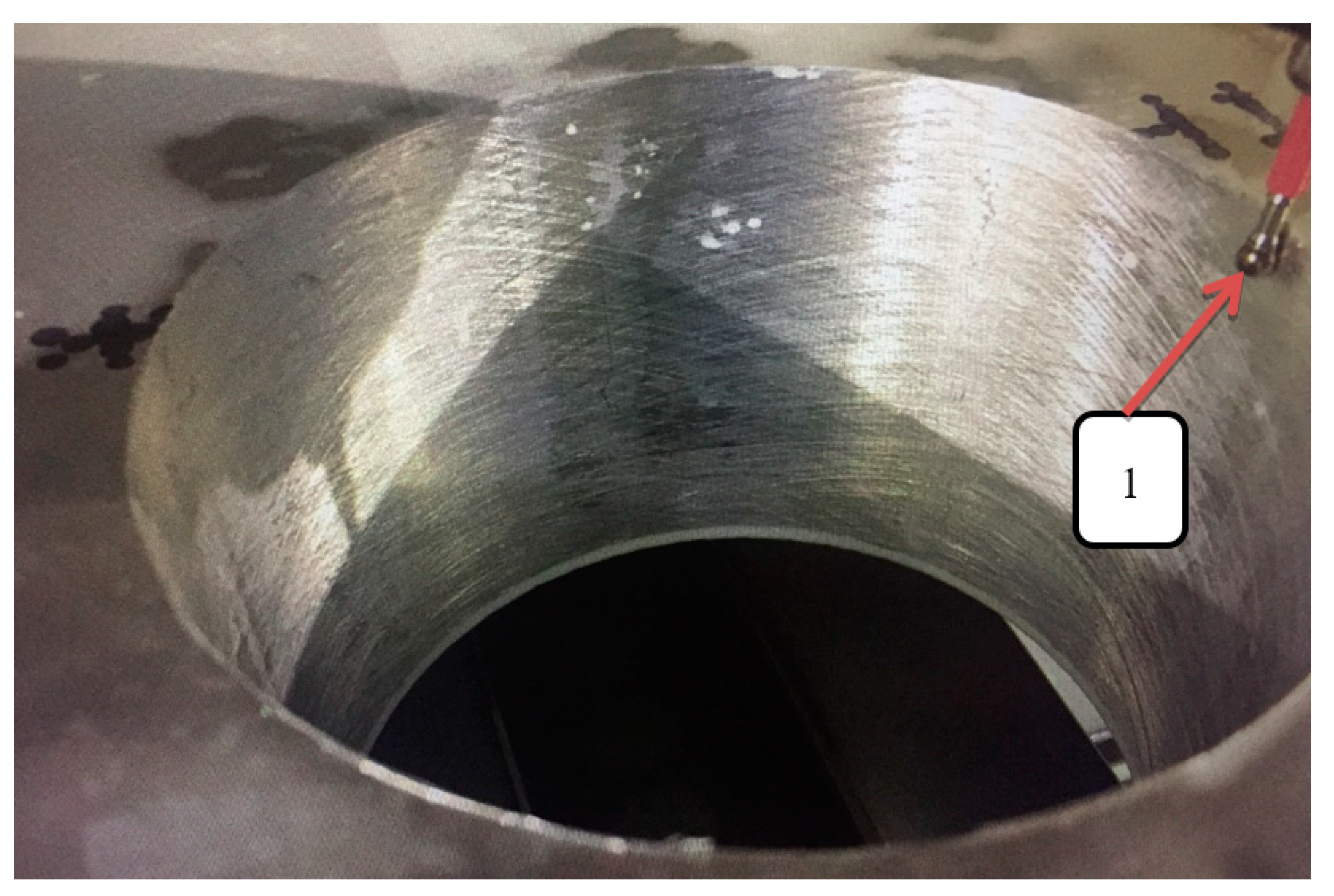
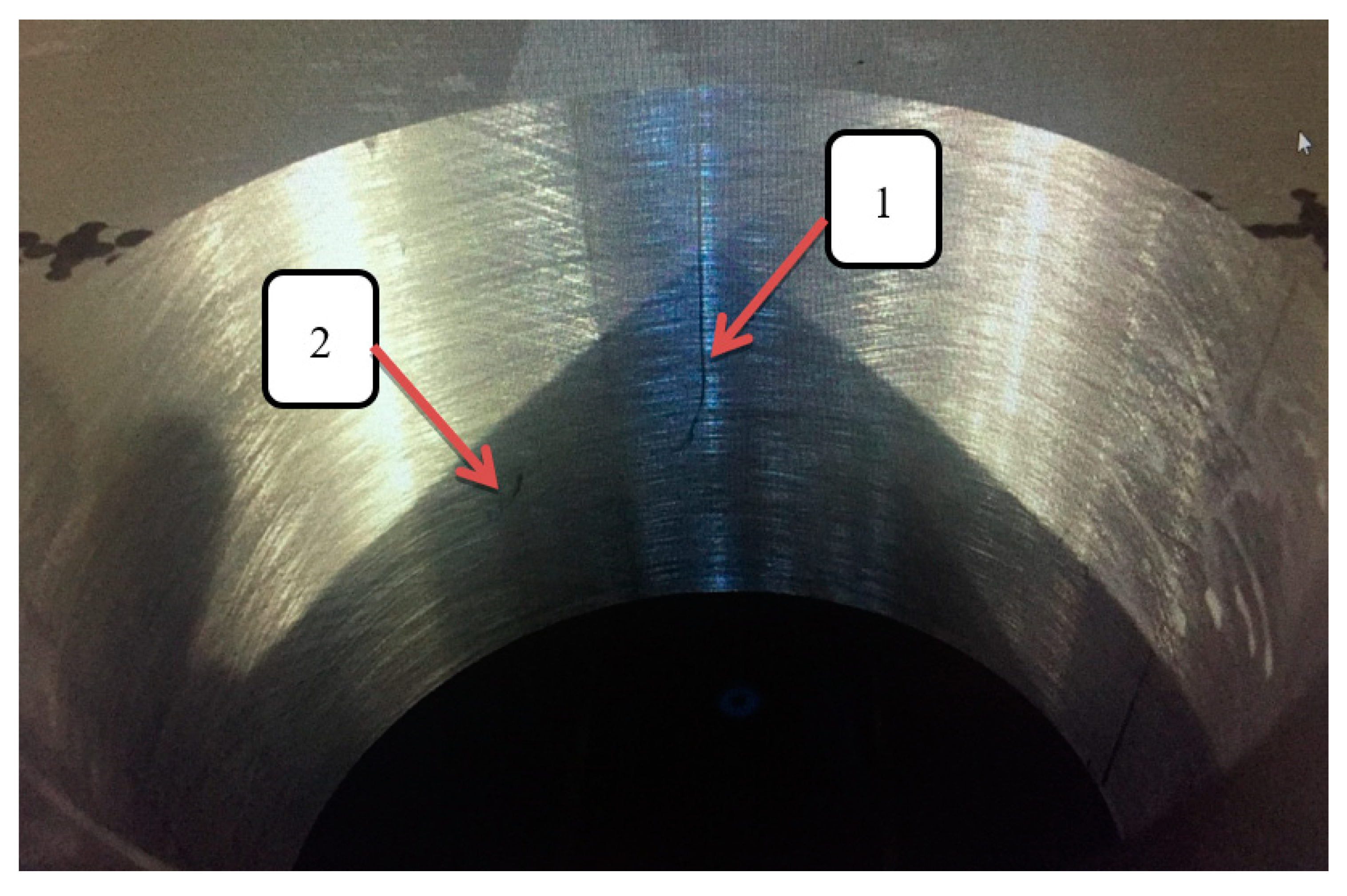
3.5.1. Supervising of Surface Textures

Figure 13 shows the surface obtained after honing with a variable value of the linear feed of the honing head. Variable honing kinematics, unlike traditional kinematics, enables the creation of oil scratches with new, and never used earlier, shapes of abrasive grain trajectories. The literature clearly shows the advantages of honing with variable kinematics, which reduces the wear of the machining tool and with surfaces with lower roughness profile parameters, e.g., Ra and Rpk.
Figure 14 and Figure 15 shows examples of surfaces obtained after honing, on which, in addition to measuring the deviation in the shape of roundness and cylindricity and the parameters of the roughness profile, the quality of received texture of machined hole is checked.
Figure 14 shows the surface after honing, without texture defects.
Figure 15 shows the surface after honing, with texture defects in the form of: 1—scratches, 2—point heterogeneity. The quality of the obtained surface is determined by the homogeneity of the dimensions, shape, and texture of the obtained surface after honing process.
Figure 16 shows the verification of the obtained oil channel pattern in a schematic manner. The verification consists in checking whether the obtained oil channels are continuous, or whether they are clogged with fragments of the honed workpiece’s material. The individual layers of neural networks check whether the image fragment shows an oil channel shape is a line, whether it is a curve, whether the shape is broken, or the break is caused by the intersection of oil channels or the presence of the workpiece material in the oil channel. In the event that the verification would confirm a significant number of oil channel breaks, the shape of the grain path should change, and the treatment should ensure the minimum number of places with a break for oil flow.

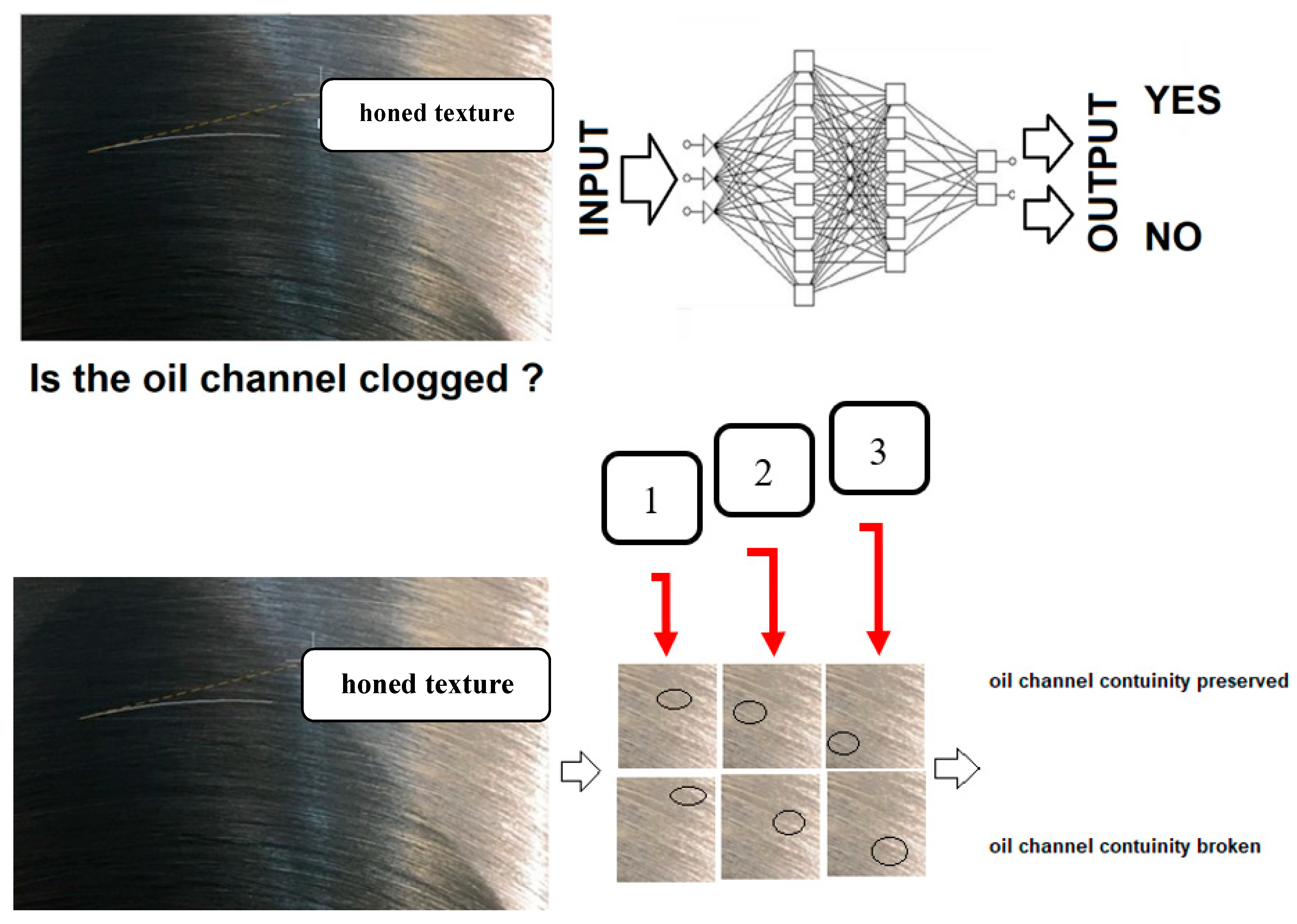
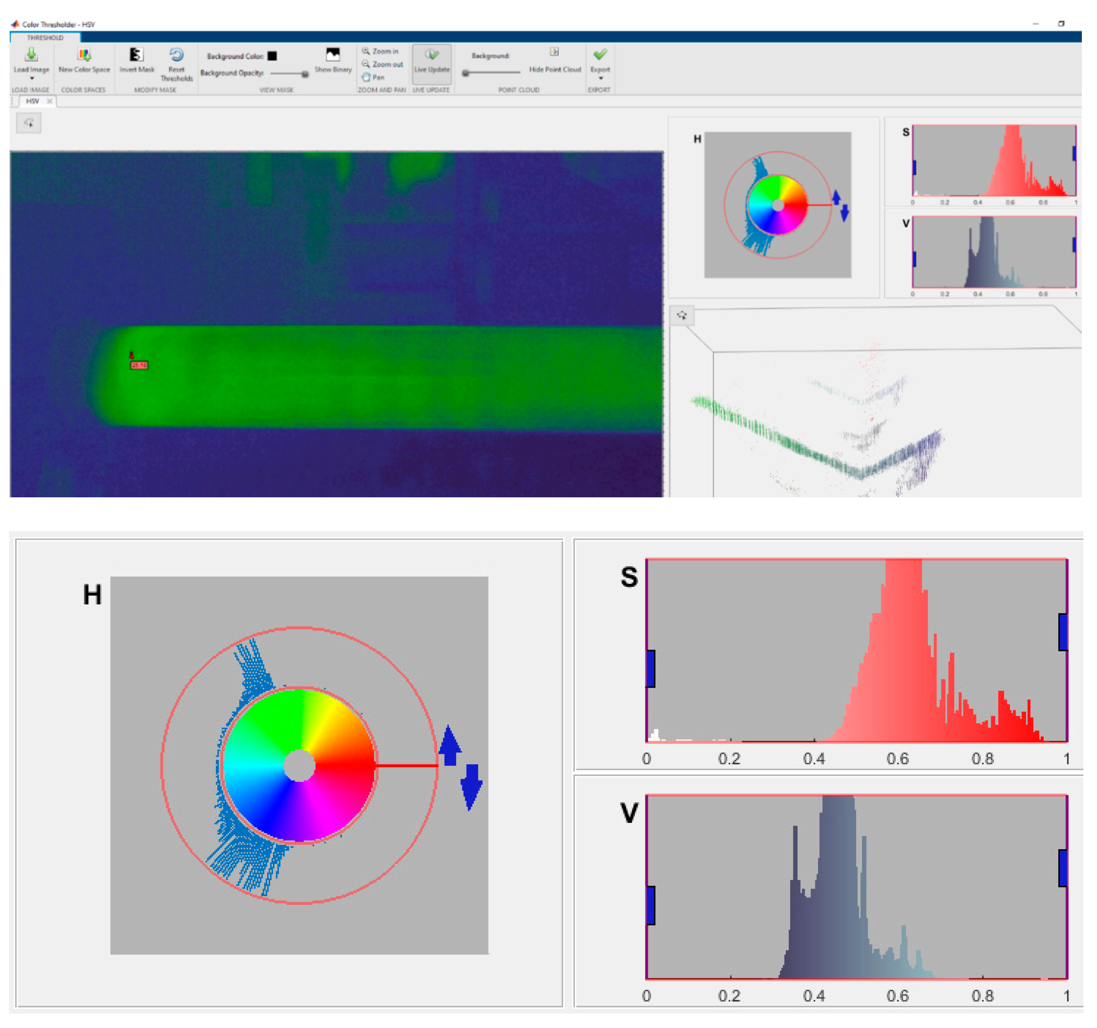
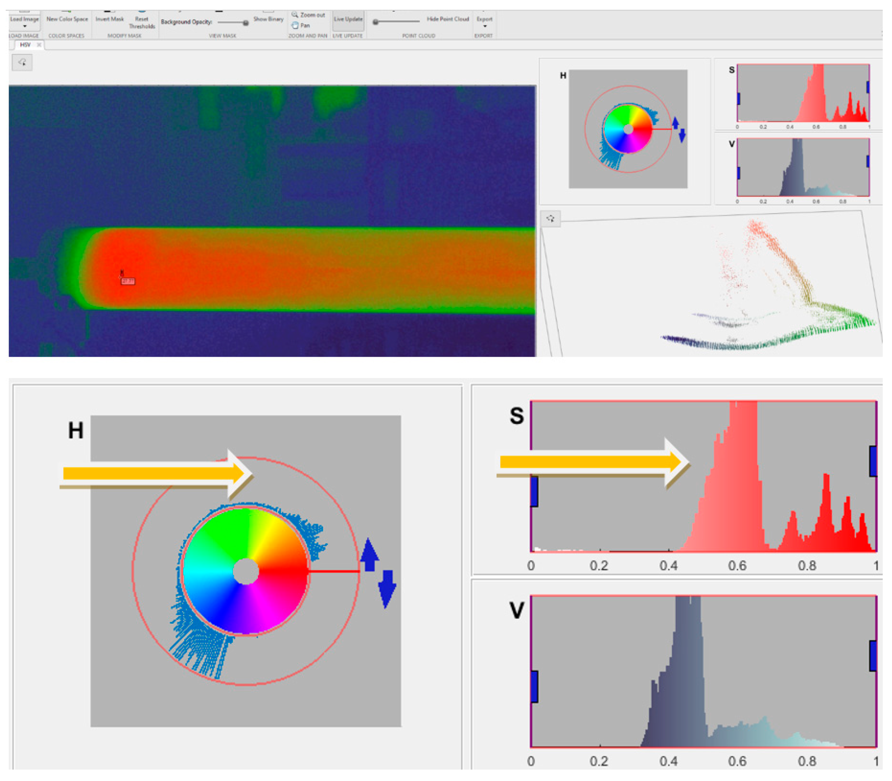
3.5.2. Analysis of Image of Honed Workpieces in Matlab’s Image Processing Toolbox

Figure 17 shows a cone representing the HSV color description method. Each color has its own shade, brightness, and value by which the color can be defined.
At the beginning of the honing process, the workpiece temperature is equal to the ambient temperature. During processing, the temperature of the workpiece increases, which causes thermal deformations of the honed hole. The temperature rise of the item can be observed on-line through the Matlab Image Processing Toolbox module.

3.6. Correcting of Honing Parameters

The honing cell should include a CNC honing machine, a thermal infrared camera, a microphone, and modules of e.g., Matlab’s software for on-line image and sound level spectrum analysis, an oil cooler and a CCR (curve curvature radius) module—the matching module of the shape of the abrasive grain trajectories received on developed surface of the machined workpieces to a certain thickness of the cross section of the honed workpiece.
Figure 18 shows possible actions to be performed during the honing process by automated honing cell: (a) FEM mesh overlay and working pressure setting, (b) determination of thermal conditions, (c) deformation, sound level and image analysis, (d) determination of honing parameters, (e) honing with variable kinematics setting with CCR module, (f) receiving variable shape of abrasive grain trajectories optimized to manufacturing conditions.
Figure 19 shows schematically the process parameters verified on-line during the treatment. Depending on the values of the obtained parameters, the values of the machining parameters would be corrected automatically.
The main factor influencing the differentiation of efficiency of manufacturing is the lack of the need to multiple cool the honed workpieces before the end of the honing process, and lack of the multiple measurements of the obtained diameter and shape deviation of honed hole.

4. Results

Performing numerical simulations makes it easier to plan the machining process. Owing to the simulation, we can find out the size of deformations and stresses occurring during honing, which allows us to decide on the selection of the right machining parameters.
Owing to the sound signal level analysis and thermal image of honed workpieces analysis one can establish the needed parameters of the honing process.

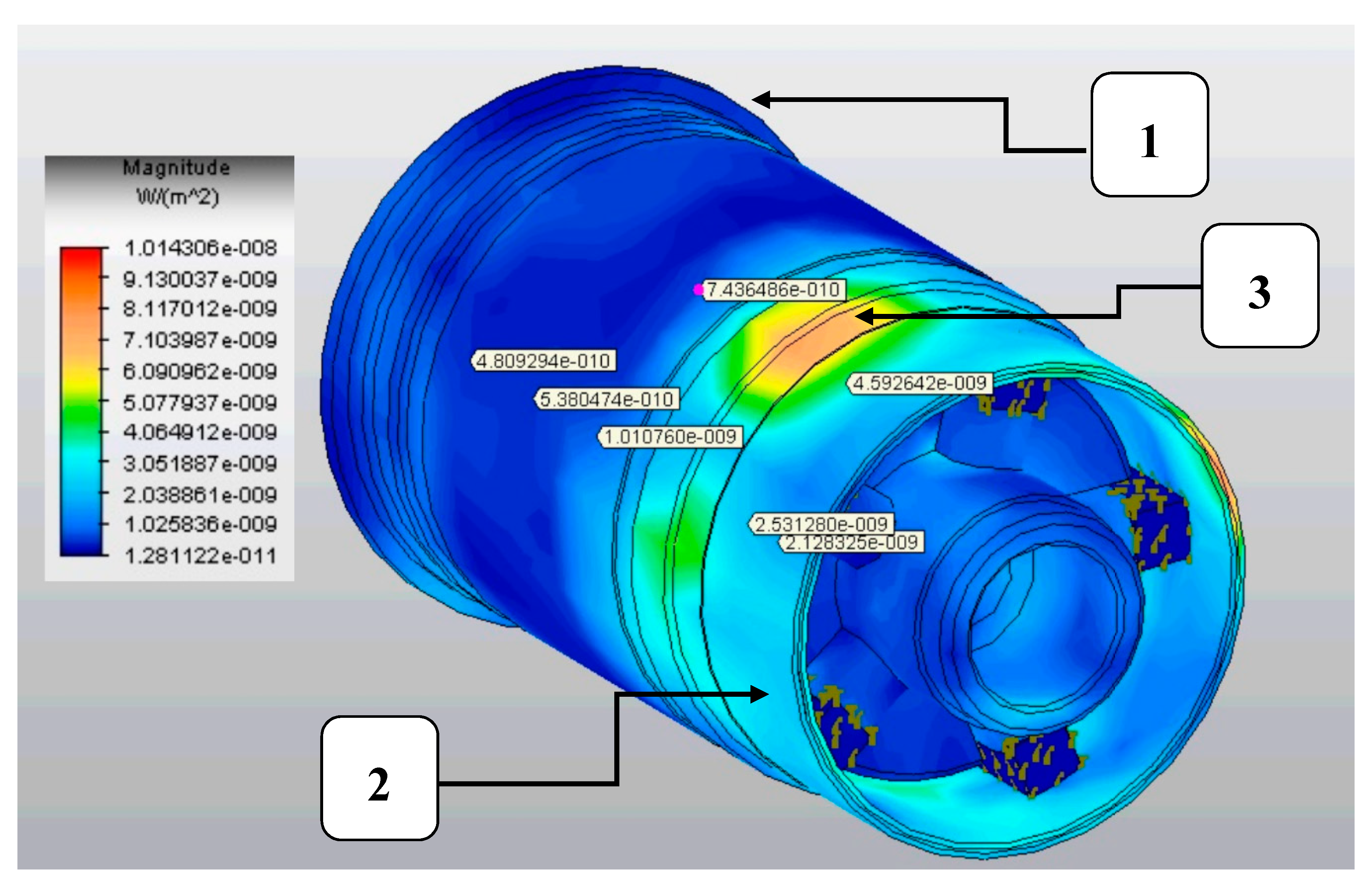
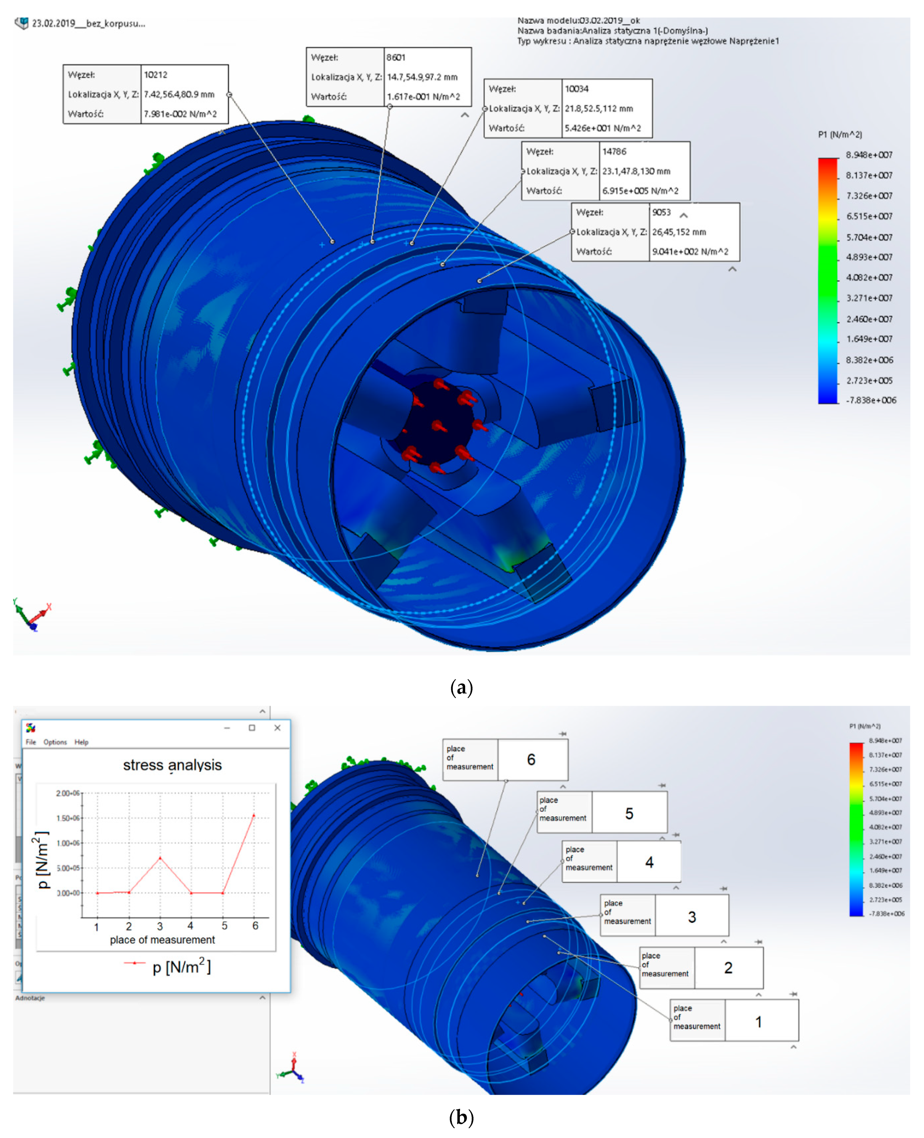
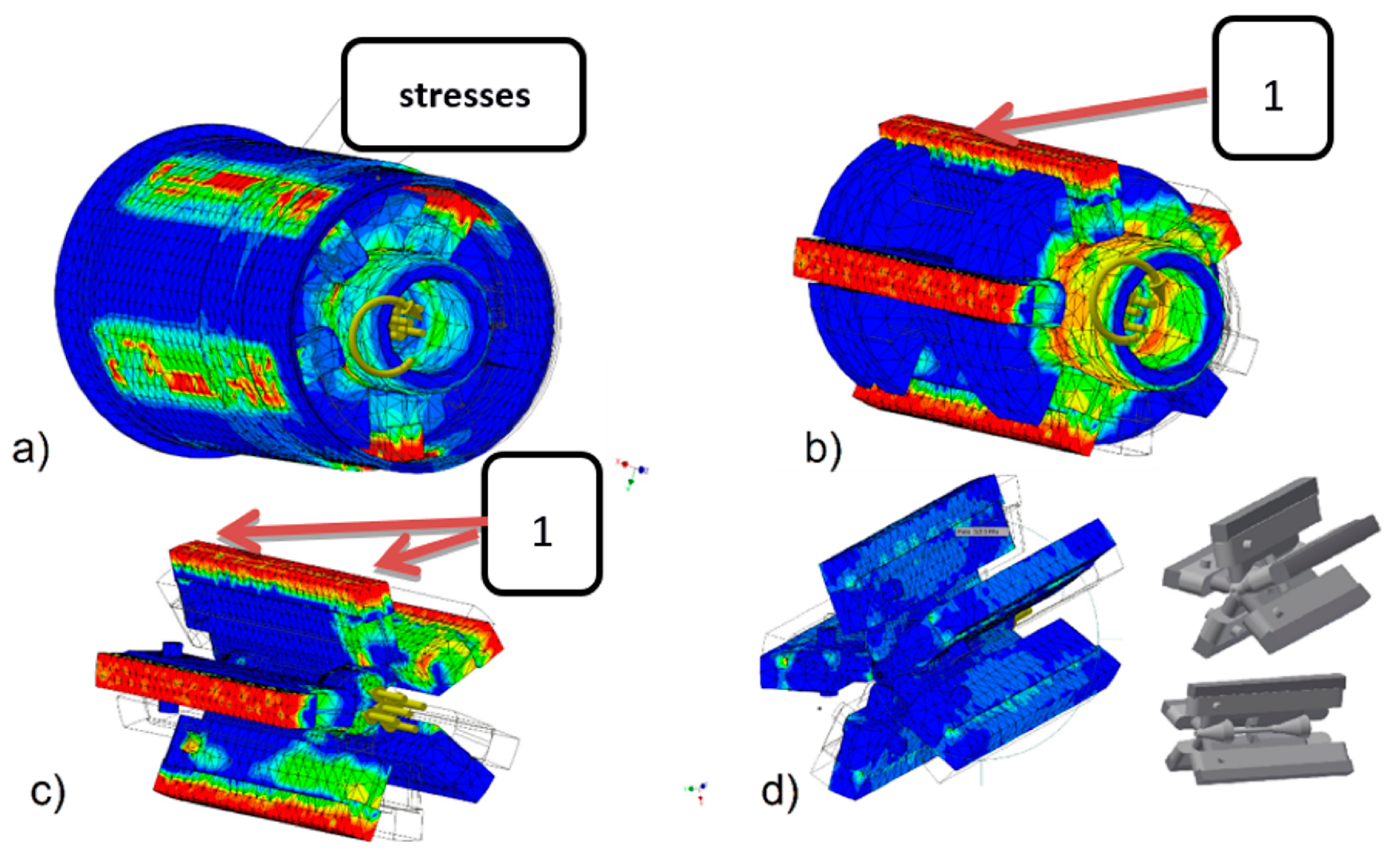
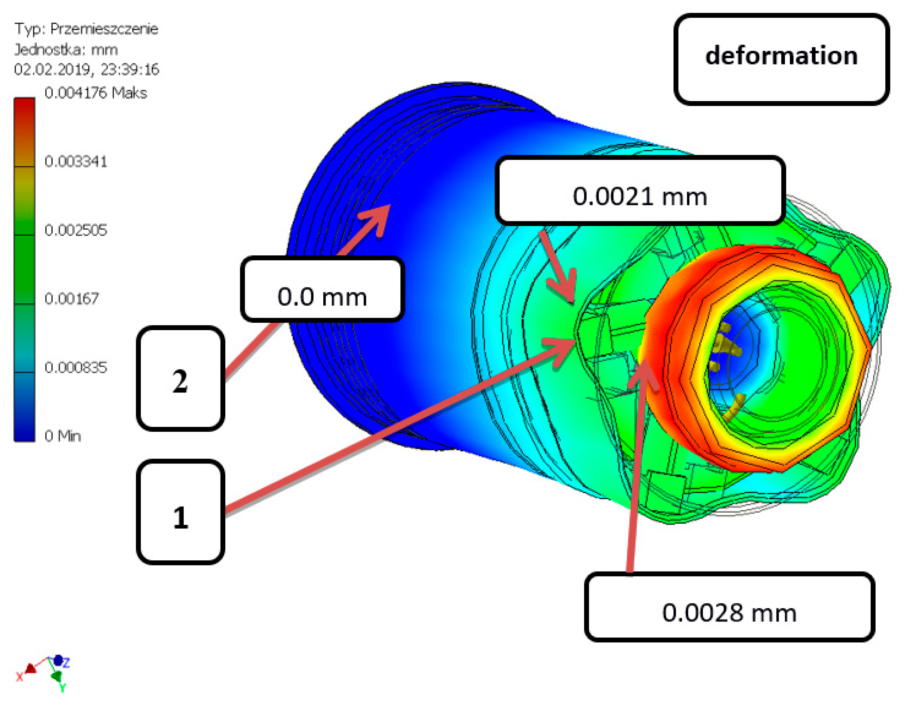
4.1. Stresses and Deformations in Machined Workpieces

In Figure 20 digit 1 indicates the location of the stress measurement, that the honing cell could monitor online. A honing head with the ability to measure the amount of pressure of the whetstone on the treated surface would allow for the verification of the shape deviation of the honed hole.
Figure 21 shows the numerical inhomogeneous simulation values of the deformation of the honed hole obtained during honing of thin-walled workpiece with a variable wall thickness, which shows the actual manufacturing difficulties of this type of workpieces.

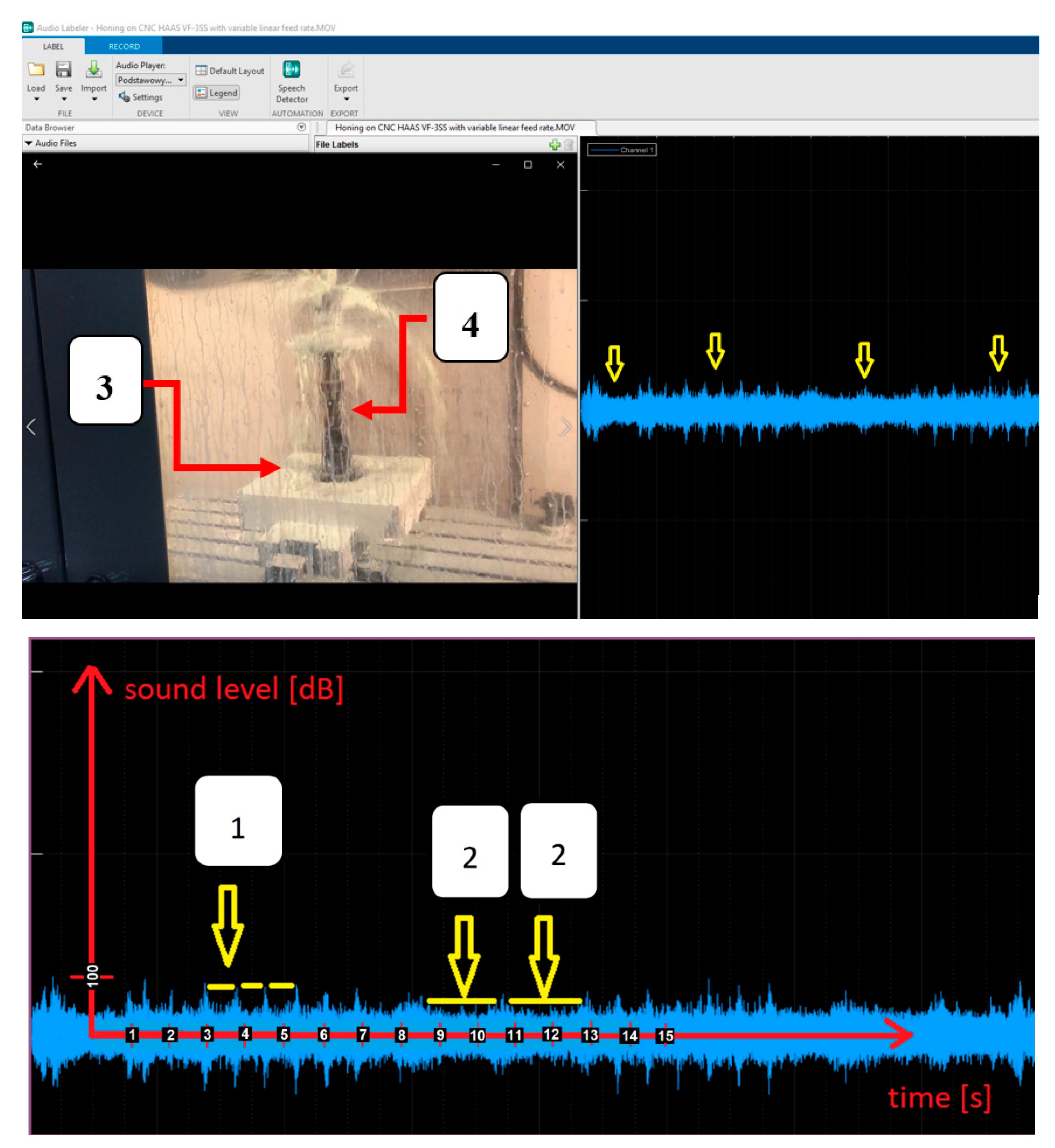
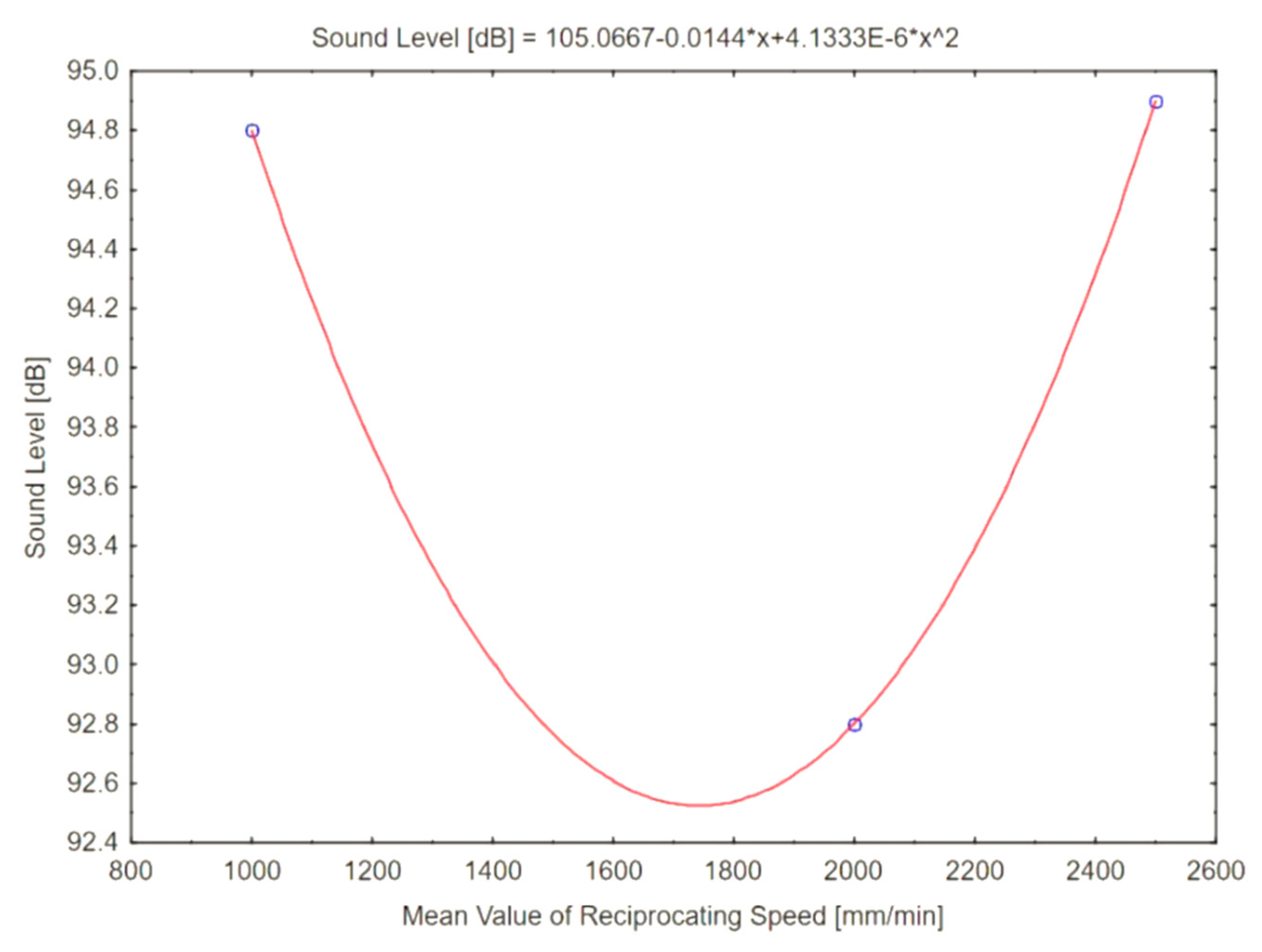
4.2. Analysis of Sound Signal Level, Received During Honing Process, in Matlab’s Audio Toolbox

Figure 22 shows a graph of the intensity of the sound signal, which was obtained during honing with varying kinematics. Measured sound was introduced into the Matlab Audio Toolbox. Distance from peak to peak in horizontal direction, in the diagram shown in Figure 22, indicates the time of the honing cycle (movement of the striking head up and down). Similarly, to Buj-Corral I. [2], it has been verified that the choice of honing parameters is reflected by the amount of sound signal emission (Figure 22), which means that the acoustic signal analysis is a good tool for verifying the honing process. Figure 23 shows the test stand with the equipment for measuring the sound intensity level.
Figure 24 shows the sound pressure level for different mean values of the variable stroke feed of the honing head. Figure 24 shows that the lower value of the sound intensity level is obtained for the mean value range of the variable stroke feed of the honing head.
A lower sound level [dB] value means the occurrence of lower cutting forces, associated with the occurrence of lower cutting forces for the middle range of the applied feed.

4.3. Analysis of Image of Honed Workpieces in Matlab’s Image Processing Toolbox

Figure 25 and Figure 26 show the temperatures of the processed object obtained during honing. Using the HSV description method, it was proposed to analyze the temperature distribution over the surface of the entire object. Instead of checking the highest temperature to which the honed object has heated up, an analysis of the uniformity of the temperature of the entire object was proposed. As shown in Figure 25, the temperatures analyzed in the Matlab Image Processing Toolbox module (value and degree of heating of the object) are verified using the Hue, Value, and Saturation parameter.
It can be clearly noticed that in Figure 26, i.e., on the workpiece after processing (heated from honing), the H parameters shift to the right toward the red shade, which means that the workpiece has heated up (the recorded thermogram shows a higher temperature than at the beginning of the treatment). The value and saturation of the color, the S and V parameters, respectively, also shift to the right, which suggests an increase in the temperature value on a larger surface of the object to be polished.
The task of the automatic cell is to monitor the degree of heating of the object, while the H parameter takes the appropriate color value, the S and V parameters respectively will confirm that the object has been heated evenly over the entire surface.
As shown in Figure 26 the hotter the temperature of honed workpiece, the more bright red color. Figure 26 also shows the shifting of the amount of the measured light color to the right, i.e., toward the lighter colors, by means of arrows.
The analysis of the thermogram, in contrast to the analysis of only the maximum temperature of the workpiece, can provide information about the local temperature increase of the honed workpiece during machining, which provides comprehensive knowledge about the temperature rise in the workpiece for different cross-section thicknesses and for different places on the honed hole.
Figure 27 shows a window view from the FlexSim 2020 simulator in which a simulation of honing on an automated cell was prepared and compared to conventional honing. The automatic cell enables more than 20 times faster production than in the conventional way.

5. Discussion

Building a test stand with all components listed in the article will allow to produce workpieces of complex shapes with different wall thickness and required specifications. The proposed honing cell consists of CNC honing center with honing equipment, thermographic camera, profilographometer, sound intensity measuring device, software for a thermographic camera, software for a roughness gauge, software for a sound level meter, cooling nozzle, measuring instruments—a diaphragm gauge, and computers enabling simultaneous observation of changes of data for individual instruments could enable the automation of honing process and the reduction of manufacturing time.
When changing the machining parameters and when switching the honing process on and off, individual devices had to be turned on, set, turned off, and properly turned on and off for collecting data in a dedicated software. After setting up the tooling, it was necessary to upload the appropriate program to the CNC machine, turn on individual devices and their dedicated software.
A very advantageous solution would be to create a honing cell with all listed elements implemented in honing machine and used simultaneously during honing.
The automatic honing cell could monitor on-line the temperature of the honed workpiece, the pressure of the whetstones obtained during machining, the sound level of honing process, and depending on the honing process conditions, it could automatically, using the CCR module, create an abrasive grain path shape with an appropriate radius of curve curvature to improve machining conditions. An important conclusion is the possibility of about a 20-fold increase in the efficiency of serial production of honing thin-walled objects

6. Conclusions

Performing a simulation of machining before the honing process enables the selection of machining parameters before the process begins, it would be particularly valuable to program the shape of the grain trajectory with a specific value of the curve radius adjusted to the honed workpieces.
The measurement of the sound intensity in the honing process is a valuable source of information because the value of the sound level is directly related to the processing conditions, which is easily noticeable in the way that the lower sound level corresponds to the lower cutting forces occurring at a given processing time.
The temperature increase of the honed workpieces can be monitored during the honing process, the advantage of the HSV method is the fact that we analyze the temperature distribution over the entire smoothed surface, and not only collect information about the maximum temperature obtained, this method has many advantages, mainly that it can control the temperature distribution in such a way that the honing process heats the workpiece uniformly.
Supervision and control of the honing process enables about twenty-fold reduction of the time needed to perform honing machining of thin-walled objects and of variable thicknesses of workpieces, because of the elimination of the need to divide the processing into several stages, followed by cooling to the ambient temperature, in which diameter of the honed hole can be measured.
The analysis of the surface texture obtained during honing process, with the use of the neural networks, allows for quick verification whether the obtained surface has a uniform texture shape of the obtained oil channels or whether additional corrective machining passes of honing head are required.

Author Contributions

Conceptualization, P.S.; methodology, P.S.; software, P.S.; validation, A.B.; formal analysis, A.B.; investigation, P.S.; resources, P.S.; data curation, P.S.; writing—original draft preparation, P.S.; writing—review and editing, A.B.; visualization, P.S.; supervision, A.B.; project administration, A.B. All authors have read and agreed to the published version of the manuscript.

Funding

This research received no external funding.

Acknowledgments

The authors thank for co-financing the Mazovia/0127/19 project by the National Center for Research and Development.

Conflicts of Interest

The authors declare no conflict of interest. The funders had no role in the design of the study; in the collection, analyses, or interpretation of data; in the writing of the manuscript, or in the decision to publish the results.

References

  1. Barylski, A.; Sender, P. Research on the increase in diameter and temperature of objects during honing long holes in production conditions. Mechanic 2014, 9, 34–43. [Google Scholar]
  2. Buj, I.; Álvarez-Flórez, J.; Domínguez-Fernández, A. Acoustic emission analysis for the detection of appropriate cutting operations in honing processes. Mech. Syst. Signal Process. 2018, 99, 873–885. [Google Scholar] [CrossRef]
  3. Buj-Corral, I.; Vivancos-Calvet, J.; Setien, I.; Sebastian, M.S. Residual stresses induced by honing processes on hardened steel cylinders. Int. J. Adv. Manuf. Technol. 2016, 88, 2321–2329. [Google Scholar] [CrossRef]
  4. González-Rojas, H.A.; Vivancos-Calvet, J.; Salcedo, M.C. Thermal Analysis of Honing Process. Mater. Sci. Forum 2006, 526, 235–240. [Google Scholar] [CrossRef]
  5. Sender, P.G. Curve Curvature Analysis of a Grain Trajectories in Variable Honing of Cylindrical Holes of Thin Wall Cylinder Liners as a Honing Process Optimization Strategy. In Innovations Induced by Research in Technical Systems; Majewski, M., Kacalak, W., Eds.; Springer: Cham, Switzerland, 2020; pp. 81–93. [Google Scholar]
  6. Sender, P. Influence of the abrasive grain trajectory on the machining of thin-walled cylinder liners of internal combustion engines with variable kinematics of honing. Autobus Tech. Eksploat. Syst. Transp. 2018, 19, 634–641. [Google Scholar] [CrossRef] [Green Version]
  7. Sender, P. Variable Kinematics of Honing Process—Influence on Machined Workpiece. In Proceedings of the Trends in the Development of Machinery and Associated Technology, TMT 2018, Karlovy Vary, Czech Republic, 18–22 September 2018; Available online: https://www.tmt.unze.ba/proceedings2018.php (accessed on 9 September 2018).
  8. Sender, P.G. Numerical simulations of honing process of thin wall cylinder liners, with constant and with variable thickness of wall of honed parts. Mach. Technol. Mater. 2019, 13, 338–344. [Google Scholar]
  9. Yokoyama, K.; Ichimiya, R. Analysis of Thermal Deformation of Workpiece in Honing Process: 3rd Report Numerical Analyses of Cylindrical and Non-Cylindrical Workpieces; Bulletin of the Japan Society of Precision Engineering: Tokyo, Japan, 1982. [Google Scholar]
  10. Yokoyama, K.; Ichimiya, R.; Iwata, K.; Moriwaki, T. Analysis of Thermal Deformation on Workpiece on Honing Process: 5th Report Thermal Effects Due to Heat Capacity of Workpiece and Kind of Honing Stone; Bulletin of the Japan Society of Precision Engineering: Tokyo, Japan, 1985. [Google Scholar]
  11. Jatti, P.; Mench, R.G. Developing an auto sizing system for vertical honing machine. Int. J. Recent Res. Civ. Mech. Eng. 2015, 1, 6–15. [Google Scholar]
  12. Deja, M.; List, M.; Lichtschlag, L.D.; Uhlmann, E. Thermal and technological aspects of double face grinding of Al2O3 ceramic materials. Ceram. Int. 2019, 45, 19489–19495. [Google Scholar] [CrossRef]
  13. Yuan, S.; Huang, W.; Wang, X. Orientation effects of micro-grooves on sliding surfaces. Tribol. Int. 2011, 44, 1047–1054. [Google Scholar] [CrossRef]
  14. Khanov, A.M.; Muratov, K.R.; Gaszew, E.A.; Pepelyszewie, A.V. Kinematics of honing methods. Russ. Acad. Sci. 2011, 13, 4. [Google Scholar]
  15. Podgaetski, M.; Scherbina, K. Kinematics of cutting holes in honing spiral spring hone. Autobus Tech. Eksploat. Syst. Transp. 2015, 6, 2409–9392. [Google Scholar]
  16. Podgaetski, M.; Sczerbina, K.K. УТВОРЕННЯ СКЛАДНОЇ ТРАЄКТОРІЇ РУХУ ЗЕРНА ПРИ ХОНІНГУВАННІ ОТВОРІВ. Кіровоградський національний технічний університет, м. Кіровоград, Україна, n° УДК 621.923.5. Available online: https://core.ac.uk/download/pdf/84824964.pdf (accessed on 27 October 2020).
  17. Yousfi, M.; Mezghani, S.; Demirci, I.; El Mansori, M. Tribological performances of elliptic and circular texture patterns produced by innovative honing process. Tribol. Int. 2016, 100, 255–262. [Google Scholar] [CrossRef] [Green Version]
  18. Ogorodov, V.A. Hole shaping in the honing of thin-walled cylinders. Russ. Eng. Res. 2017, 37, 549–553. [Google Scholar] [CrossRef]
  19. Schmitt, R.; König, N.; Zheng, H. Machine integrated optical measurement of honed surfaces in presence of cooling lubricant. J. Phys.: Conf. Ser. 2011, 311, 012007. [Google Scholar] [CrossRef] [Green Version]
  20. Tripathi, B.N.; Singh, N.K.; Vates, U.K. Surface Roughness Influencing Process Parameters & Modeling Techniques for Four Stroke Motor Bike Cylinder Liners during Honing: Review. Int. J. Mech. Mech. Eng. 2015, 15, 1. [Google Scholar]
  21. Voronov, S.A. Development of Mathematical Methods for the Analysis of Dynamics of Hole Finishing Processes; Moscow State Technical University: Moscow, Russia, 2008. [Google Scholar]
  22. Wang, J.; Shao, Y.; Zhu, X. Kinematics analysis and experimental study on ultrasonic vibration honing. In Proceedings of the International Technology and Innovation Conference 2009 (ITIC 2009), Xi’an, China, 12–14 October 2009. [Google Scholar] [CrossRef]
  23. Xi, C.; Hu, X.; Zhang, Z. Research for cylindricity prediction model of inner-hole honing. In Proceedings of the 2011 Second International Conference on Mechanic Automation and Control Engineering (MACE), Inner Mongolia, China, 15–17 July 2011; pp. 1506–1509. [Google Scholar]
  24. Zhang, Y.; Yang, Y.; Niu, J.; Gong, J. (Eds.) Study on the Impact of Honing Machine Reciprocating Reversing Acceleration upon Reticulate Pattern Trajectory. In Proceedings of the 1st International Conference on Mechanical Engineering and Material Science, Shanghai, China, 18–20 December 2020; pp. 17–20. [Google Scholar]
  25. Arantes, L.J.; Fernandes, K.A.; Schramm, C.R.; Leal, J.E.S.; Piratelli-Filho, A.; Franco, S.D.; Arencibia, R.V. The roughness characterization in cylinders obtained by conventional and flexible honing processes. Int. J. Adv. Manuf. Technol. 2017, 93, 635–649. [Google Scholar] [CrossRef]
  26. Buj-Corral, I.; Vivancos-Calvet, J.; Rodero-De-Lamo, L.; Marco-Almagro, L. Comparison between Mathematical Models for Roughness Obtained in Test Machine and in Industrial Machine in Semifinish Honing Processes. Procedia Eng. 2015, 132, 545–552. [Google Scholar] [CrossRef] [Green Version]
  27. Deepak Lawrence, K.; Ramamoorthy, B. Multi-surface topography targeted plateau honing for the processing of cylinder liner surfaces of automotive engines. Appl. Surf. Sci. 2016, 365, 19–30. [Google Scholar] [CrossRef]
  28. Kadyrov, R.; Charikov, P.N.; Pryanichnikova, V.V. Honing process optimization algorithms. IOP Conf. Series: Mater. Sci. Eng. 2018, 327, 022052. [Google Scholar] [CrossRef] [Green Version]
  29. Pawlus, P.; Michalski, J.; Reizer, R. Progress in cylinder honing. In Part I: Honing of Blind Holes; Rusek, P., Ed.; Instytut Zaawansowanych Technologii Wytwarzania: Kraków, Poland, 2012. [Google Scholar]
  30. Schmitt, C.; Klein, S.; Bähre, D. An Introduction to the Vibration Analysis for the Precision Honing of Bores. Procedia Manuf. 2015, 1, 637–643. [Google Scholar] [CrossRef] [Green Version]
  31. Gouskov, A.; Voronov, S.A.; Butcher, E.A.; Sinha, S. Non-Conservative Oscillations of a Tool for Deep Hole Honing; Elsevier: Amsterdam, The Netherlands, 2006; pp. 685–708. [Google Scholar]
  32. Iskra, A.; Kałużny, J. Influence of the actual shape of the piston side surface on the parameters of the oil film. J. KONES Intern. Combust. Engines 2000, 7, 1–2. [Google Scholar]
  33. Schmitt, C.; Bähre, D. Analysis of the Process Dynamics for the Precision Honing of Bores. Procedia CIRP 2014, 17, 692–697. [Google Scholar] [CrossRef] [Green Version]
  34. Schmitt, C.; Bähre, D. An Approach to the Calculation of Process Forces During the Precision Honing of Small Bores. Procedia CIRP 2013, 7, 282–287. [Google Scholar] [CrossRef] [Green Version]
  35. Zhang, X.; Wang, X.; Wang, D.; Yao, Z.; Xi, L.; Wang, X. Methodology to Improve the Cylindricity of Engine Cylinder Bore by Honing. J. Manuf. Sci. Eng. 2016, 139, 031008. [Google Scholar] [CrossRef]
  36. Grzesik, W. Influence of surface textures produced by finishing operations on their functional properties. J. Mach. Eng. 2016, 16, 15–23. [Google Scholar] [CrossRef]
  37. Babiczew, A.P.; Poljanchikov, J.I.; Slavin, A.V. Gładzenie. Министерство Образования и Науки Российской Федерации. Волгогр. Гос. Архит.-Строит. ун-т; Донской гос. техн. ун-т.: Волгоград, Russia, 2013. [Google Scholar]
  38. Chavan, P.S.; Harne, M.S. Effect of Honing Process Parameters on Surface Quality of Engine Cylinder Liners. Int. J. Eng. Res. Technol. 2013, 2, 4. [Google Scholar]
  39. Gashev, E.A.; Muratov, K.R. Tool motion in the honing of cylindrical surfaces. Russ. Eng. Res. 2014, 34, 268–271. [Google Scholar] [CrossRef]
  40. Goeldel, B.; El Mansori, M.; Dumur, D. Macroscopic simulation of the liner honing process. CIRP Ann. 2012, 61, 319–322. [Google Scholar] [CrossRef] [Green Version]
  41. Goeldel, B.; El Mansori, M.; Dumur, D. Simulation of Roughness and Surface Texture Evolution at Macroscopic Scale During Cylinder Honing Process. Procedia CIRP 2013, 8, 27–32. [Google Scholar] [CrossRef] [Green Version]
  42. Grabon, W.; Pawlus, P.; Wos, S.; Koszela, W.; Wieczorowski, M. Effects of honed cylinder liner surface texture on tribological properties of piston ring-liner assembly in short time tests. Tribol. Int. 2017, 113, 137–148. [Google Scholar] [CrossRef]
  43. Jocsak, J. The Effects of Surface Finish on Piston Ring-Pack Performance in Advanced Reciprocating Engine Systems. Master’s Thesis, Massachusetts Institute of Technology, Boston, MA, USA, 2005. [Google Scholar]
  44. Johansson, S.; Nilsson, P.H.; Ohlsson, R.; Anderberg, C.; RosénB, -G. Optimization of the Cylinder Liner Surface for Reduction of Oil Consumption. In World Tribology Congress III; Imperial College Press: London, UK, 2005; pp. 559–560. [Google Scholar]
  45. Johansson, S.; Nilsson, P.H.; Ohlsson, R.; Anderberg, C.; Rosén, B.-G. New cylinder liner surfaces for low oil consumption. Tribol. Int. 2008, 41, 854–859. [Google Scholar] [CrossRef]
  46. Khanov, A.M.; Gashev, E.A.; Muratov, K.R. Formation of raster trajectories in the honing of cylindrical surfaces. Russ. Eng. Res. 2013, 33, 423–426. [Google Scholar] [CrossRef]
  47. Khanov, A.M.; Muratov, K.R.; Gashev, E.A.; Muratov, R.A. Kinematic potential of honing machines. Russ. Eng. Res. 2011, 31, 607–609. [Google Scholar] [CrossRef]
  48. Knoll, G.; Rienacker, A. Tribology in Automotive Engine Aplications; Technical report for Institute for Machine Elements and Design; University of Kassel: Kassel, Germany, 2011. [Google Scholar]
  49. Mezghani, S.; Demirci, I.; Yousfi, M.; El Mansori, M. Mutual influence of crosshatch angle and superficial roughness of honed surfaces on friction in ring-pack tribo-system. Tribol. Int. 2013, 66, 54–59. [Google Scholar] [CrossRef] [Green Version]
  50. Muratov, K.R.; Gashev, E.A. Methods of precision hole honing. Ph.D. Thesis, Perm National Research Polytechnic University, Perm Krai, Russia, 2014. [Google Scholar]
  51. Obara, R.; Souza, R.M.; Tomanik, E. Quantification of folded metal in cylinder bores through surface relocation. Wear 2017, 384, 142–150. [Google Scholar] [CrossRef]
  52. Pawlus, P.; Cieslak, T.; Mathia, T. The study of cylinder liner plateau honing process. J. Mater. Process. Technol. 2009, 209, 6078–6086. [Google Scholar] [CrossRef]
  53. Buj, I.; Vivancos-Calvet, J. Roughness variability in the honing process of steel cylinders with CBN metal bonded tools. Precis. Eng. 2011, 35, 289–293. [Google Scholar] [CrossRef]
  54. Buj-Corral, I.; Sivatte-Adroer, M.; Llanas-Parra, X. Adaptive indirect neural network model for roughness in honing processes. Tribol. Int. 2020, 141, 105891. [Google Scholar] [CrossRef]
  55. Goeldel, B.; Voisin, J.; Dumur, D.; El Mansori, M.; Frabolot, M. Flexible right sized honing technology for fast engine finishing. CIRP Ann. 2013, 62, 327–330. [Google Scholar] [CrossRef] [Green Version]
  56. Buyukli, I.; Kolesnik, V. Improving accuracy of holes honing. Odes’kyi Polite-Universytet Pr. 2015, 215, 34–43. [Google Scholar] [CrossRef] [Green Version]
  57. Bouassida, H. Lubricated piston ring cylinder liner contact: Influence of the Liner Microgeometry. INSA de Lyon, Dostępne na Stronie Internetowej. 2014. Available online: http://theses.insa-lyon.fr/publication/2014ISAL0088/these.pdf (accessed on 1 January 2019).
  58. Corral, I.B.; Vivancos-Calvet, J.; Salcedo, M.C. Use of roughness probability parameters to quantify the material removed in plateau-honing. Int. J. Mach. Tools Manuf. 2010, 50, 621–629. [Google Scholar] [CrossRef]
  59. Entezami, S.S.; Farahnakian, M.; Akbari, A. Experimental Study of Effective Parameters on Honing Process of Cast Iron Cylinder. J. Mod. Process. Manuf. Prod. 2015, 4, 3. [Google Scholar]
  60. Karpuschewski, B.; Welzel, F.; Risse, K.; Schorgel, M. Reduction of Friction in the Cylinder Running Surface of Internal Combustion Engines by the Finishing Process. Procedia CIRP 2016, 45, 87–90. [Google Scholar] [CrossRef] [Green Version]
  61. Mansori, M.E.; Goeldel, B.; Sabri, L. Performance impact of honing dynamics on surface finish of precoated cylinder bores. Surf. Coatings Technol. 2013, 215, 334–339. [Google Scholar] [CrossRef] [Green Version]
  62. Brush Research Manufacturing Co. Inc. A study of a Cylinder Wall Micro-Structure. 03/18/2018. Available online: http://info.brushresearch.com/study-of-cylinder-wall-micro-structure (accessed on 1 January 2019).
  63. Dahlmann, D.; Denkena, B. Hybrid tool for high performance structuring and honing of cylinder liners. CIRP Ann. 2017, 66, 113–116. [Google Scholar] [CrossRef]
  64. Demirci, I.; Mezghani, S.; Yousfi, M.; El Mansori, M. Impact of superficial surface texture anisotropy in helical slide and plateau honing on ring-pack performance. Proc. Inst. Mech. Eng. Part J J. Eng. Tribol. 2016, 230, 1030–1037. [Google Scholar] [CrossRef] [Green Version]
  65. Deshpande, A.K.; Bhole, H.A.; Choudhari, L.A. Analysis of Super-Finishing Honing Operation with Old and New Plateau Honing Machine Concept. Int. J. Eng. Res. Gen. Sci. 2015, 3, 812–818. [Google Scholar]
  66. Fiat Chrysler America. Chrysler IIIH Engine Assembly Manual DRAFT; Fiat Chrysler America: Auburn Hills, MI, USA, 2016. [Google Scholar]
  67. Grabon, W.; Pawlus, P.; Sep, J. Tribological characteristics of one-process and two-process cylinder liner honed surfaces under reciprocating sliding conditions. Tribol. Int. 2010, 43, 1882–1892. [Google Scholar] [CrossRef]
  68. Michalski, J.; Woś, P. The effect of cylinder liner surface topography on abrasive wear of piston–cylinder assembly in combustion engine. Wear 2011, 271, 582–589. [Google Scholar] [CrossRef]
  69. Reizer, R.; Pawlus, P.; Galda, L.; Grabon, W.; Dzierwa, A. Modeling of worn surface topography formed in a low wear process. Wear 2012, 278, 94–100. [Google Scholar] [CrossRef]
  70. Kim, J.-K.; Xavier, F.-A.; Kim, D.-E. Tribological properties of twin wire arc spray coated aluminum cylinder liner. Mater. Des. 2015, 84, 231–237. [Google Scholar] [CrossRef]
  71. Kapoor, J. Parametric Investigations into Bore Honing through Response Surface Methodology. Mater. Sci. Forum 2014, 808, 11–18. [Google Scholar] [CrossRef]
  72. KS Motor Service International GmbH. Honing of Gray Cast Iron Cylinder Blocks. Available online: http://file.seekpart.com/keywordpdf/2011/3/30/2011330113527501.pdf (accessed on 18 March 2018).
  73. Mezghani, S.; Demirci, I.; Zahouani, H.; El Mansori, M. The effect of groove texture patterns on piston-ring pack friction. Precis. Eng. 2012, 36, 210–217. [Google Scholar] [CrossRef] [Green Version]
  74. Reizer, R.; Pawlus, P. 3D surface topography of cylinder liner forecasting during plateau honing process. J. Phys. Conf. Ser. 2011, 311, 1–6. [Google Scholar] [CrossRef] [Green Version]
  75. Pimpalgaonkar, M.H.; Laxmanrao, G.R.; Laxmanrao, A.D.E.S. A review of optimization process parameters on honing machine. Int. J. Mech. Prod. Eng. 2013, 1, 5. [Google Scholar]
  76. Qin, P.-P.; Yang, C.-L.; Huang, W.; Xu, G.-W.; Liu, C.-J. Honing Process of Hydraulic Cylinder Bore for Remanufacturing. In Proceedings of the 4th International Conference on Sensors, Measurement and Intelligent Materials, Shenzhen, China, 27–28 December 2016; p. 2352. [Google Scholar]
  77. Sabri, L.; Mezghani, S.; El Mansori, M.; Le Lan, J.-V.; Negro, T.D. 3D Multi-Scale Topography Analysis in Specifying Quality of Honed Surfaces. In Proceedings of the 9th Biennial Conference on Engineering Systems, Haifa, Israel, 7–9 July 2008; pp. 225–232. [Google Scholar]
  78. Polyanchikov, Y.N.; Plotnikov, A.L.; Polyanchikova, M.Y.; Kursin, O.A.; Leshukov, A.V. Honing with increase in the cutting speed. Russ. Eng. Res. 2008, 28, 727–728. [Google Scholar] [CrossRef]
  79. Yousfi, M. Tribofunctional Study of Low-Friction Engine Liner Textures Generated by Honing Process. 2014. Available online: https://pastel.archives-ouvertes.fr/tel-01148194 (accessed on 5 January 2019).
  80. Yousfi, M.; Mezghani, S.; Demirici, I.; Mansori, E.M. (Eds.) Comparative study between 2D and 3D characterization methods for cylinder liner plateau honed surfaces. In Proceedings of the 42nd North American Manufacturing Research Conference, Detroit, MI, USA, 9–13 June 2014; pp. 1–7. [Google Scholar]
  81. Yousfi, M.; Mezghani, S.; Demirci, I.; Mansori, E.M.; Zahouani, H. Energy efficiency optimization of engine by frictional reduction of functional surfaces of cylinder ring-pack system. Tribol. Int. 2013, 59, 240–247. [Google Scholar]
  82. Yousfi, M.; Mezghani, S.; Demirci, I.; Mansori, E.M. Generation of circular and elliptic low-friction texture patterns by honing process. Available online: https://www.researchgate.net/profile/Mohammed_Yousfi4/publication/305045271_Generation_of_circular_and_elliptic_lowfriction_texture_patterns_by_honing_process/links/577ff87d08ae5f367d370b77/Generation-of-circular-and-elliptic-low-friction-texture-patterns-by-honing-process.pdf (accessed on 7 September 2015).
  83. Yousfi, M.; Mezghani, S.; Demirci, I.; El Mansori, M. Mutual Effect of Groove Size and Anisotropy of Cylinder Liner Honed Textures on Engine Performances. Adv. Mater. Res. 2014, 966, 175–183. [Google Scholar] [CrossRef] [Green Version]
  84. Yousfi, M.; Mezghani, S.; Demirci, I.; El Mansori, M. Smoothness and plateauness contributions to the running-in friction and wear of stratified helical slide and plateau honed cylinder liners. Wear 2015, 332, 1238–1247. [Google Scholar] [CrossRef]
  85. Yousfi, M.; Mezghani, S.; Demirci, I.; Mansori, E.M. Texturation Mécanique Antifriction Par Rodage Du tribo-système Segment-Cylindre. Présentation du Projet D’acquisition d’un tribo-simulateur du Fonctionnement Moteur. In Proceedings of the 28 Journees Internationales Francophones de Tribologie, Lyon, France, 27–29 April 2016. [Google Scholar]
  86. Ozdemir, M.; Korkmaz, M.E.; Gunay, M.B. Optimization of surface roughness in honing of engine cylinder liners witch SiC honing stones. In Proceedings of the 1st International Conference on Engeneering Technology and Applied Sciences, Afyonkarahisar, Turkey, 21–22 April 2016. [Google Scholar]
  87. Buj-Corral, I.; Vivancos-Calvet, J.; Coba-Salcedo, M. Modelling of surface finish and material removal rate in rough honing. Precis. Eng. 2014, 38, 100–108. [Google Scholar] [CrossRef]
  88. Wang, Q.; Feng, Q.; Li, Q.; Zu Ren, C. The Experimental Investigation of Stone Wear in Honing. Key Eng. Mater. 2011, 487, 462–467. [Google Scholar] [CrossRef]
  89. Voronov, S.A.; Gouskov, A.; Bobrenkov, O.A. Modelling of bore honing. Int. J. Mechatronics Manuf. Syst. 2009, 2, 566. [Google Scholar] [CrossRef]
  90. Zhang, X.; Zhu, X.; Cheng, L. The Influence Study of Ultrasonic honing parameters to workpiece surface temperature. MATEC Web Conf. 2016, 45, 4008. [Google Scholar] [CrossRef] [Green Version]
Figure 1. Honing head with main honing speeds; 1—honed cylinder liner, 2—abrasive whetstone, 3—expanding mandrel, 4—pressure and machined diameter measurement, 5—temperature measurement, 6—vision system.
Machines 08 00070 g001
Figure 2. Possible directions of movement of honing head in honing of cylindrical holes: 1—abrasive grain trajectories, 2—expanding of honed surface, 3—honed cylinder liners with honing head, 4—additional honing head oscillation motion in vertical direction, 5—additional honing head oscillation motion in horizontal direction, 6—additional oscillation motion of honing head rotation direction.
Machines 08 00070 g002
Figure 3. Traditional kinematics of honing process, (a) constant value of honing speed, (b) constant linear speed of honing head, (c) linear value of honing head, (d) length of abrasive grain path in traditional honing process; 1—an example of abrasive grain path.
Machines 08 00070 g003
Figure 4. Variable kinematics of honing process—an example of abrasive grain trajectory obtained during honing with variable linear and tangential speed. Components of the cylindrical honing process: 1—an example of abrasive grain path received in variable kinematics of honing, 2—comparative abrasive grain path obtained in traditional honing.
Machines 08 00070 g004
Figure 5. Haas VF-3SS milling machine with honing equipment: 1—thermal imaging camera, 2—software of thermal imaging camera, 3—Mitutoyo SJ-210 roughness meter, 4—software of Mitutoyo SJ-210 roughness meter, 5—sound intensity meter, 6—vibration meter, 7—air nozzle.
Machines 08 00070 g005
Figure 6. Image from computer simulation of honing process—heat flux flow; 1—the thickest machined cross–section, 2—the thinnest honed cross-section, 3—maximum value of the measured heat flux.
Machines 08 00070 g006
Figure 7. Deformation of the honed workpieces—different value in different places. (a)view of the window from the simulator with the effect of the deformations obtained, (b) view of the window from the simulator with the presentation of non-linear deformation results of the honed workpiece.
Machines 08 00070 g007
Figure 8. Examples of different grain trajectory shapes, shown on the developed surface of machined hole, with different oscillation frequency, with different path length for the same length on horizontal direction of the treated surface. The function marked with digit 1 has one change of the head movement direction in the lower and upper turning point. The function marked with digit 2 has one change in the head movement direction in the lower turning point and two changes in the direction of the upper turning point.
Machines 08 00070 g008
Figure 9. Programming in non-conventional way by adding oscillation frequency and amplitude’s high to circular path generated in CAD/CAM system; 1—entering parameters, 2—circular path, 3—the resulting sinusoidal trajectory.
Machines 08 00070 g009
Figure 10. The method of modifying the shape of the machining path in CAD/CAM system Alphacam.
Machines 08 00070 g010
Figure 11. Idea of honing process with abilities to control the abrasive whetstone and honing head movements in both direction: 1—honing head body; 2—expanding pin for abrasive whetstones; 3—abrasive whetstone; 4—possible TWO-WAY direction of movement control; 5—automatic vision system.
Machines 08 00070 g011
Figure 12. Machining tool: 1—new whetstone; 2—damaged whetstone; 3—worn whetstone.
Machines 08 00070 g012
Figure 13. Obtained texture of the honed surface for variable stroke speed of honing head in the range of 1000–3000 mm/min—average value of tangent angle to the grain trajectory of 14°; 1—sample abrasive grain path; 2—tangent line to the abrasive grain path.
Machines 08 00070 g013
Figure 14. Example of a honed surface without texture defects, 1—probe tip.
Machines 08 00070 g014
Figure 15. An example of a honed surface with texture defects: 1—scratch; 2—point flaw.
Machines 08 00070 g015
Figure 16. Verification of the shape and it’s continuity of oil channels using a neural network. The numbers indicate the stages of the subsequent stages of surface texture verification.
Machines 08 00070 g016
Figure 17. Cone showing the color description method named HSV.
Machines 08 00070 g017
Figure 18. Schematic diagram of honing algorithm: (a) FEM mesh overlay and working pressure setting, (b) determination of thermal conditions, (c) deformation, sound level and image analysis, (d) determination of honing parameters, (e) honing with variable kinematics setting with CCR module, (f) receiving variable shape of abrasive grain trajectories optimized to manufacturing conditions.
Machines 08 00070 g018
Figure 19. Schematic diagram of automated honing process.
Machines 08 00070 g019
Figure 20. Results of numerical analysis of honing process of cylinder linear with different thickness of cross-section; (a) simulation result of the entire assembly, (b) assembly simulation result without cylinder linear, (c) assembly simulation result without cylinder linear and without honing head body, (d) simulation of stresses obtained during honing process.
Machines 08 00070 g020
Figure 21. Numerical simulation—deformation of a cylinder with a variable wall thickness: 1—the greatest cylindrical deformation value of honed workpiece; 2—the smallest cylindrical deformation value of honed workpiece.
Machines 08 00070 g021
Figure 22. Matlab Audio Labeler—analysis of sound level vs honing process time conducted on CNC vertical milling machine Haas VF-3SS. Honing with variable kinematics condition, with different value of honing head stroke speed; 1—shorter honing cycle time, 2—longer honing cycle time, 3—honed workpiece, 4—honing equipment.
Machines 08 00070 g022
Figure 23. Test stand: 1 equipment for measuring of the sound intensity level.
Machines 08 00070 g023
Figure 24. Sound intensity level depending on the average value of the variable head feed, obtained during honing with variable kinematics.
Machines 08 00070 g024
Figure 25. Matlab Image Colour Thresholder—analysis of thermogram of honed workpiece on CNC vertical milling machine Haas VF-3SS (earlier stage of honing (than on Figure 26). H—hue, S—Saturation, and V—Value (HSV).
Machines 08 00070 g025
Figure 26. Matlab Image Colour Thresholder—analysis of thermogram of honed part on CNC vertical milling machines Haas VF-3SS (later stage of honing process than shown on Figure 25). H—hue, S—Saturation, and V—Value (HSV).
Machines 08 00070 g026
Figure 27. Window from the FlexSim 2020 simulator—comparison of production on a conventional station and on an automatic cell; 1—automated honing cell (efficiency of automated honing cell: 11.6 workpieces/h), 2—conventional honing cell (efficiency of traditional honing: 0.5 workpiece/h). 3 and 4—FlexSim 2020 simulation’s algorithms of honing process in Process Flow.
Machines 08 00070 g027
Table 1. The honing angles discussed in the literature.
Authors or CompaniesLiterature Item NumberHoning Angle [°]
Bouassida H.[57]45
Entezami S., Farahnakian M., Akbari A.,[59]
Karpuschewski B., Welzel F., Risse K., Schorgel M.[60]
Mansori El. M., Goeldel B., Sabri L.[61]
Brush research manufacturing Co. Inc.[62]25–30
Buj-Corral I., Vivancos-Calvet J.[3]36.9; 38.6; 53.1
Chavan P.S., Harne M.S.[38]46–57
Dahlmann D., Denkena B.[63]110
Graboń W., Pawlus P., Wos S., Koszela W., Wieczorowski M.[42]15.5; 55; 72; 125
Demirci I., Mezghani S., Yousfi M., El Mansori M.[64]50–130
Deshpande A.K., Bhole H.A., Choudhari L.A.[65]25–75
Fiat Chrysler America[66]36
Goeldel B., Mansori M.,[40]50
Graboń W., Pawlus P., Sep J.[67]
Michalski J., Woś P.[68]
Reizer R., Pawlus P., Galda L., Graboń W., Dzierwa A.[69]
Pawlus P., Cieslak T., Mathia T.,[52]
Goeldel B., Mansori M.,[55]45, 135
Jocsak J.[43]30, 35, 40, 45, 60, 90
Johansson S., Nilsson Per.H., Ohlsson R., Anderberg C., Rosen B.G.[44]40, 140
Johansson S., Nilsson Per.H., Ohlsson R., Anderberg C., Bengt-Goran Rosen[45]
Kim J.K., Xavier F.A., Kim D.E.[70]
Kapoor J.,[71]15–22
Knoll G., Rienacker A.,[48]10, 30, 60, 90, 120, 150, 170
KS Motor Service International GmbH[72]40, 60, 80
Lawrence D.K., Ramamoorthy B.[27]41, 48, 51, 54, 59, 61, 64, 71, 74, 84, 88, 89, 102, 105, 111
Mezghani S., Demirci I., Yousfi M., Mansori E.M.[49]40–60; 120–140
Mezghani S., Demirci I., Zahouani H., Mansori E.M.[73]10, 20, 30, 40, 50, 60, 70, 80, 100, 110, 130, 140, 150
Obara R.B., Souza R.M.[51]66
Reizer R. Pawlus P.[74]53
Pimpalgaonkar M.H.,[75]20–60
Qin P.P., Yang C.I., Huang W., Xu G.W., Liu C.J.[76]30, 45
Sabri L., Mezghani S., Mansori E.M., Le Lan Jean-Vincent[77]51.14; 30–60; 140
Gashev E.A., Muratov K.R.,[39]variable angle
Polyanchikov Yu. N., Plotniko A.L., Polyanchikova M.Yu., Kursin O.A.,[78]
Sender P.[5,6,7,8]
Yousfi M.[79,80,81,82,83,84,85]
Tripathi B.N., Singh N.K., Vates U.K.[20]25–75
Yuan S., Huang W., Wang X.,[13]45, 90
Deepak Lawrence K., Ramamoorthy B.[27]43, 50, 53, 56, 60, 63, 68, 74, 79, 81, 94, 106, 108, 114
Ozdemir M., Korkmaz M.E., Guanay M.B.Buj-Corral I., Vivancos-Calvet J., Coba-Salcedo M.[86]
[87]
40–80
Q. Wang, Q. Feng, Q.F. Li and C.Z. Ren[88]83.70
Publisher’s Note: MDPI stays neutral with regard to jurisdictional claims in published maps and institutional affiliations.

