Letter

Limited-Position Set Model-Reference Adaptive Observer for Control of DFIGs without Mechanical Sensors

by
Mohamed Abdelrahem
1,2,*,
Christoph M. Hackl
3 and
Ralph Kennel
1,*
1
Insitute for Electrical Drive Systems and Power Electronics (EAL), Technische Universität München (TUM), 80333 Munich, Germany
2
Electrical Engineering Department, Faculty of Engineering, Assiut University, Assiut 71516, Egypt
3
Department of Electrical Engineering and Information Technology, Munich University of Applied Sciences, 80335 Munich, Germany
*
Authors to whom correspondence should be addressed.
Machines 2020, 8(4), 72; https://doi.org/10.3390/machines8040072
Submission received: 5 October 2020 / Revised: 9 November 2020 / Accepted: 10 November 2020 / Published: 12 November 2020
(This article belongs to the Special Issue Design and Control of Rotating Electrical Machines)

Abstract

:
Operations of the doubly-fed induction generators (DFIGs) without mechanical sensors are highly desirable in order to enhance the reliability of the wind generation systems. This article proposes a limited-position set model-reference adaptive observer (LPS-MRAO) for control of DFIGs in wind turbine systems (WTSs) without mechanical sensors, i.e., without incremental encoders or speed transducers. The concept of of the developed LPS-MRAO is obtained from the finite-set model predictive control (FS-MPC). In the proposed LPS-MRAO, an algorithm is presented in order to give a constant number of angles for the rotor position of the DFIG. By using these angles, a certain number of rotor currents can be predicted. Then, a new quality function is defined to find the best angle of the rotor. In the proposed LPS-MRAO, there are not any gains to tune like the classical MRAO, where a proportional-integral is used and must be tuned. Finally, the proposed LPS-MRAO and classical one are experimentally implemented in the laboratory and compared at various operation scenarios and under mismatches in the parameters of the DFIG. The experimental results illustrated that the estimation performance and robustness of the proposed LPS-MRAO are better than those of the classical one.

1. Introduction

The conventional power generation systems produce a large amount of carbon dioxide, which increases the temperature of the planet, i.e., global warming. Accordingly, severe consequences are currently seen in our life like ice melting, forest fires, and others. Therefore, the main goal of the Paris agreement is to reduce this increase in the global average temperature to safe our planet [1]. One method to do that is the use of renewable energy systems instead of the conventional ones. Wind energy is very important source between the different types of renewable energy systems. The first type of the wind turbines was a constant-speed one with a squirrel-cage induction generator (SCIG) [2,3,4]. The SCIG consumes a reactive power, which is usually provided by a capacitor bank. The main features of the fixed-speed wind turbines are simplicity and low initial cost. However, the fixed-speed wind turbines have the following disadvantages: (1) The conversion efficiency is low, (2) operation at constant speed, i.e., the changes in the wind speed directly affect the electrical utility, and (3) high sensitivity to voltage dips and faults on the grid. Considering these drawbacks, it can be observed that the constant-speed wind generators have almost disappeared in the wind turbines market [2,3,4].
The disadvantages of the constant-speed wind turbines encouraged the development of variable speed wind generators. The doubly-fed induction generator (DFIG) is currently the main variable-speed wind generator on the market [2,3,4]. The DFIGs have the following advantages:
  • High energy conversion efficiency due to the implementation of the maximum power point tracking (MPPT) technique.
  • Changes of the wind speed does not affect the electrical utility.
  • No capacitor bank is required.
  • The price of the power electronics circuits is low due to the use of partial-scale back-to-back (BTB) power converter, i.e., 30 % of the generator power.
Generally, the control of the DFIG is realized by vector control and implemented in the rotating d q reference frame [5,6,7]. Therefore, the measurement of the rotor position and speed is necessary. Incremental encoders and speed transducers are extensively used for measuring the rotor position and speed. However, the high failure rate of these mechanical sensors is the main drawback. Therefore, in order to improve the reliability of the wind generation system with DFIG, estimation of the rotor position and speed of the DFIG is highly requested [8].
In the literature, a lot of observers for estimating the rotor position and speed of the DFIG have been presented. The popular estimators are: phase locked loop (PLL) [9], model-reference adaptive observers (MRAOs) [10,11,12,13,14,15], sliding-mode observers [16], extended Kalman filter (EKF) [17,18,19], unscented Kalman filter (UKF) [20,21], and others. Due to its simplicity and direct physical interpretation, MRAO received high interest from the researchers. MRAO can be designed based on stator current, stator flux, rotor current, rotor flux, or back-electro-motive force. The comparison between the different types of MRAOs have been presented in [11]. Based on this comparison, MRAO based on rotor current illustrated better response than the other types. Usually, the main parts of MRAOs are: reference model, adaptive model, and an adaptation mechanism. Most of the developed adaption mechanisms of MRAOs uses proportional-integrator (PI) regulators with constant gains [10,11,12,13,14,15]. The PI controllers give good dynamic and steady-state performances. However, the narrow bandwidth of those PI controllers is the main drawback. Furthermore, in the tuning of these PI controllers, a trade-off between the overshoot, oscillations, and damping must be considered. Therefore, other controllers such as neural network [22], fuzzy logic [23], and sliding mode [23,24] have been used in the adaption mechanisms of MRAOs instead of the PI controller.
In 2007, the so-called finite-set model predictive control (FS-MPC) has been presented for two-level voltage source inverters [25]. The basic idea of the FS-MPC is the use of the limited number of switching states of the voltage source inverter to predict a certain number of currents in the next sample. Subsequently, a cost function is formulated to select the optimal switching state to directly apply in the next sampling interval without the use of a modulator. The FS-MPC has the following advantages:
  • Simple and easy to understand.
  • Non-linear control system and no modulator is required.
  • Constrains can by easily considered in the design of the FS-MPC.
  • Multi-variable control problem can be easily handled by the FS-MPC.
Accordingly, the FS-MPC has been then applied for several power electronics circuits and motor drive systems [26,27,28,29,30,31], where the FS-MPC gives excellent dynamic performance without overshoot and oscillations. However, the FS-MPC is rarely used in observers [32,33,34]. In [33], a finite-position-set phase-locked loop (FPS-PLL) is proposed for estimation of the rotor position and speed of a permanent-magnet synchronous generator (PMSG). In this FPS-PLL, the concept of the FS-MPC is used instead of the PI controller. According to the experimental results presented in [33], the dynamic performance and robustness of the FPS-PLL are better than the traditional PLL. Furthermore, in [34], the concept of the FS-MPC is used in MRAO for sensorless control of PMSGs, where the dynamics and robustness of the proposed MRAO are enhanced. This fact motivated us to use the principles of FS-MPC in MRAO for a different machine (i.e., DFIG).
In this paper, a limited-position set model-reference adaptive observer (LPS-MRAO) for control of DFIGs without mechanical sensors is proposed. Due to the fact that the rotor position did not has a limited number of states like the power electronics circuits, an algorithm is developed to produce this finite number of angles. Subsequently, those angles are used in the adaptive model of the proposed LPS-MRAO to estimate a certain number or rotor currents and by the help of a cost function, the best angle for the rotor position is found. This optimal angle is then differentiated to obtain the rotor speed of the DFIG. The proposed LPS-MRAO and classical one are experimentally implemented and compared. The results illustrated that the response of the proposed LPS-MRAO is better than that of the classical MRAO.
This paper is organized as follows: Section 2 explains the model and control of the DFIG. The traditional MRAO for DFIGs is given in Section 3, while the proposed LPS-MRAO for DFIGs is detailed in Section 4. The description of the experimental setup is given in Section 5 and the experimental results are presented in Section 6. Finally, Section 7 concludes the paper.

2. Modeling and Control of the DFIG

The schematic-diagram of the wind generation system with DFIG is illustrated in Figure 1, where the rotor of the DFIG is connect to a power converter called rotor-side converter (RSC) and the stator is tied with the point of common coupling (i.e., grid). In this work, the voltage-oriented control (VOC) is employed to control the DFIG. The model of the DFIG in the stationary reference frame of the stator can be expressed as
u s s ( t ) = R s i s s ( t ) + d d t ψ s s ( t ) , u r s ( t ) = R r i r s ( t ) + d d t ψ r s ( t ) ω r ( t ) J ψ r s ( t ) ,
where
ψ s s ( t ) = L s i s s ( t ) + L m i r s ( t ) ψ r s ( t ) = L r i r s ( t ) + L m i s s ( t ) .
In Equations (1) and (2), u s s = ( u s α , u s β ) [ V ] , u r s = ( u r α , u r β ) [ V ] , i s s = ( i s α , i s β ) [ A ] , i r s = ( i r α , i r β ) [ A ] , ψ s s = ( ψ s α , ψ s β ) [ Vs ] , and ψ r s = ( ψ r α , ψ r β ) [ Vs ] are the stator/rotor voltages/currents/fluxes, respectively. R s [ Ω ] and R r [ Ω ] are the resistances of the stator and rotor of the DFIG. L s [ H ] , L r [ H ] , and L m [ H ] are the stator/rotor/mutual inductances, respectively. ω r [ rad / s ]  is the electrical angular speed of the rotor and J = 0 1 1 0 .
The control system of the DFIG is usually designed in the rotating-reference frame d q . Accordingly, Park transformation is applied as follows
x k = cos ( ϕ ) sin ( ϕ ) sin ( ϕ ) cos ( ϕ ) = : T P ( ϕ ) 1 x s ,
where x k = ( x d , x q ) and x s = ( x α , x β ) . Hence, Equations (1) and (2) in the d q frame as follows [28]
u s k ( t ) = R s i s k ( t ) + d d t ψ s k ( t ) + ω s J ψ s k ( t ) , u r k ( t ) = R r i r k ( t ) + d d t ψ r k ( t ) + ( ω s ω r ( t ) ) = : ω s l ( t ) J ψ r k ( t ) ,
and
ψ s k = L s i s k + L m i r k ψ r k = L r i r k + L m i s k .
In Equation (4), ω s [ rad / s ] is the stator (grid) angular frequency.
It can be observed from Figure 1 that the d-axis component of the rotor current is used to control the active power injected to the grid. Usually, it is required to realize the maximum power point tracking (MPPT) operations of the wind turbine, i.e., achieving the highest conversion efficiency of the wind turbine. Therefore, the non-linear relation, T e = k p ω ^ m 2 with a positive constant k p  [28], is implemented to compute the optimal electro-magnetic torque of the DFIG. Subsequently, the reference current of the d-axis is obtained as follows i r , r e f d = 2 3 ω s L s n p L m T e u s d . The output reactive power of the DFIG can by regulated by the q-axis current [28].

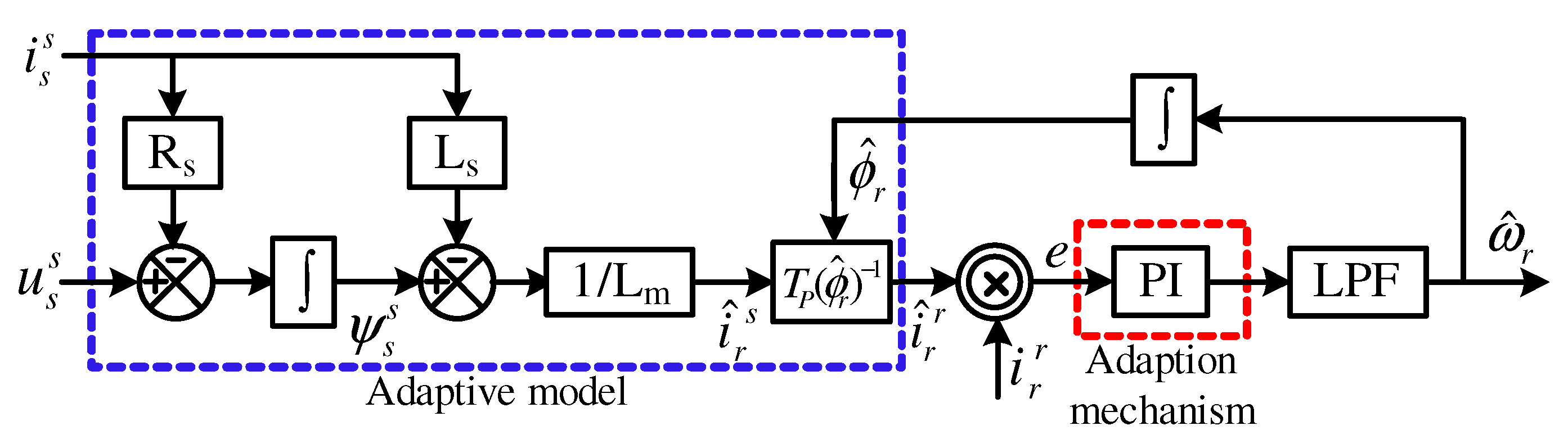
3. Traditional MRAO for DFIGs

In [11], several MRAOs have been designed and compared based on stator current, stator flux, rotor current, and rotor flux. According to this study, MRAO based on rotor current of the DFIG showed the best performance between the different types of MRAOs. Accordingly, a rotor current based MRAO is considered in this work. The block diagram of the traditional MRAO for DFIGs is depicted in Figure 2, where the adaptive model of this MRAO estimates the rotor current i ^ r s in the stator stationary reference-frame from the stator voltage u s s and stator current i s s based on Equation (2) as follows
i r s ^ ( t ) = 1 L m ψ s s ( t ) L s i s s ( t ) ,
where ψ s s ( t ) is obtained from Equation (1) as follows,
ψ s s ( t ) = 0 t u s s ( τ ) R s i s s ( τ ) d τ .
This estimated current i ^ r s is then transferred from the stator stationary reference-frame to the rotor stationary reference frame by the help of Park transformation as illustrated in Figure 2. In the MRAO-based rotor current, the reference model is very simple, which is the measured rotor current of the DFIG i r r in the rotor stationary reference frame. Then, the error between this estimated and measured rotor current is computed as follows
e : = i r r ^ × i r r = i r r ^   i r r sin Δ ϕ r .
This error e is the input of the adaption mechanism, which is a PI controller in case of the traditional MRAO. The output of the adaption mechanism is the estimated rotor speed ω ^ r of the DFIG after filtering the high frequency noise by a low-pass filter (LPF). The estimated rotor position ϕ ^ r is found by integration of the speed signal ω ^ r . Detailed design of the traditional MRAO and the tuning of the PI controller are presented in [11].

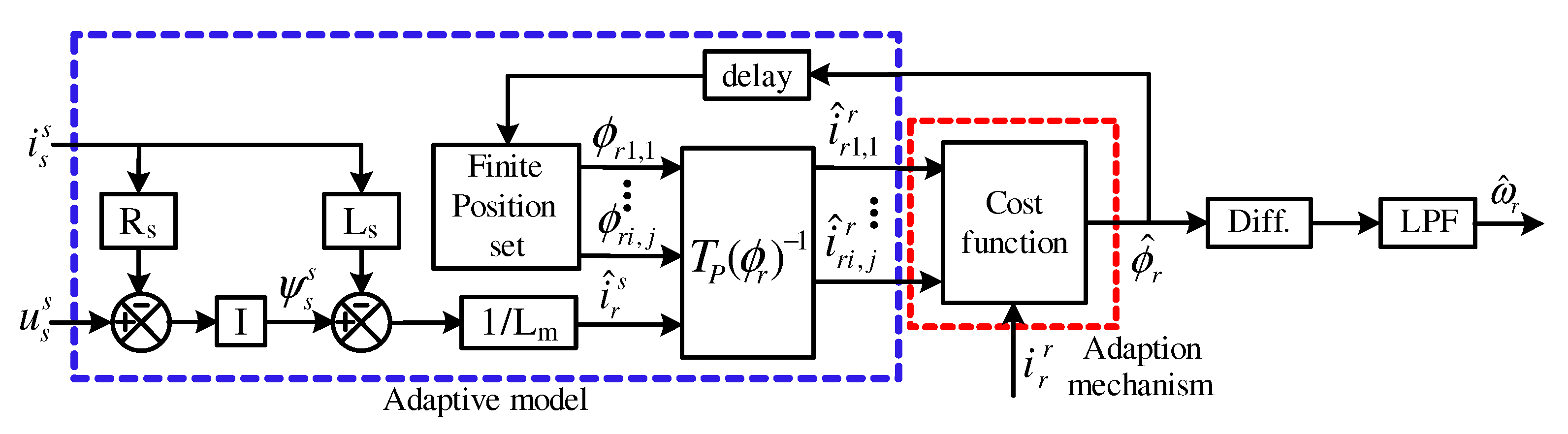
4. Proposed Limited-Position Set MRAO for DFIGs

The block-diagram of the proposed LPS-MRAO is illustrated in Figure 3. The main challenge to use the FS-MPC instead of the PI controller in the adaption mechanism of MRAOs is that the rotor positions of the DFIG are not discrete like the switching states of the power electronics circuits. Therefore, it is essential to develop an algorithm (Algorithm 1) for producing a limited number of positions. The first step of this algorithm is reading the currents of the rotor/stator i r r / i s s and stator voltage u s s . The second step is computing of the stator flux ψ s s . Then, the rotor current is observed in the stator reference frame i r s ^ . In step 4 of Algorithm 1, the limited number of rotor positions is generated by using the following equation:
ϕ r i , j = ϕ i n , i + ( j 4 ) Δ ϕ i ,
where Δ ϕ i = π 4 × 1 2 i . For more declaration, at i = 0 , Δ ϕ o = π 4 . Then, by utilizing j = 0 7 with a step of one (i.e., j = 0 , 1 , 2 , 3 , 4 , 5 , 6 , 7 ), the following angles are produced: 0, π 4 , π 2 , 3 π 4 , π , 3 π 4 , π 2 , and π 4   rad . Note that the number of these angles are 8 to be similar to the 8 switching states of the 2-level power converter. For each angle, the rotor current in the rotor reference frame is estimated as i ^ r i , j r = T P ( ϕ ^ r i , j ) 1 i r s ^ . Then, the cost function (CF) is defined as
C F i , j = i ^ r i , j α i r β i ^ r i , j β i r α = i ^ r i , j r i r r sin ( ϕ r ϕ ^ r i , j ) = : Δ ϕ r i , j .
The cost function is the cross product between the estimated rotor current i ^ r i , j r and measured one i r r . Accordingly, its value is significantly based on sin ( ϕ r ϕ ^ r i , j ) = sin ( Δ ϕ r i , j ) . Therefore, the angle that produces the minimum error between i ^ r i , j r and i r r , i.e., minimum Δ ϕ r i , j , will be chosen to be the optimal angle and the initial value of the second iteration ϕ i n , 1 . Step 4 will be iterated for 8 times to estimate the rotor position ϕ ^ r with an accuracy of Δ ϕ 7 2 = 1 2 × π 4 × 2 7 = π 1024 = 0.003 rad .
Finally, to observe the rotor speed, the observed angle ϕ ^ r is differentiated as illustrated in Figure 3. By the help of a low-pass filter (LPF), the signal of the rotor speed is filtered from the high frequencies noise.
Algorithm 1 Proposed LPS-MRAO for DFIGs
Step 1: Read the rotor and stator currents i r r , i s s and stator voltage u s s .
Step 2: Compute ψ s s ( t ) = 0 t u s s ( τ ) R s i s s ( τ ) d τ .
Step 3: Estimate i r s ^ ( t ) = 1 L m ψ s s ( t ) L s i s s ( t ) .
Step 4:  
 Initiate the angle ϕ i n , 0 = 0 and error C F i n =
For i = 0 : 1 : 7
      calculate Δ ϕ i = π 4 × 1 2 i .
         For j = 0 : 1 : 7
            compute ϕ r i , j = ϕ i n , i + ( j 4 ) Δ ϕ i .
            compute i ^ r i , j r = T P ( ϕ ^ r i , j ) 1 i r s ^ .
            evaluate the cost function C F i , j = i ^ r i , j α i r β i ^ r i , j β i r α .
               if C F i , j < C F i n
                   C F i n = C F i , j
                   ϕ r , o p t = ϕ i , j
               end
         end
      set ϕ i n , i + 1 = ϕ r , o p t
   end
Step 5: ϕ ^ r = ϕ r , o p t
Step 6: Return to Step 1.

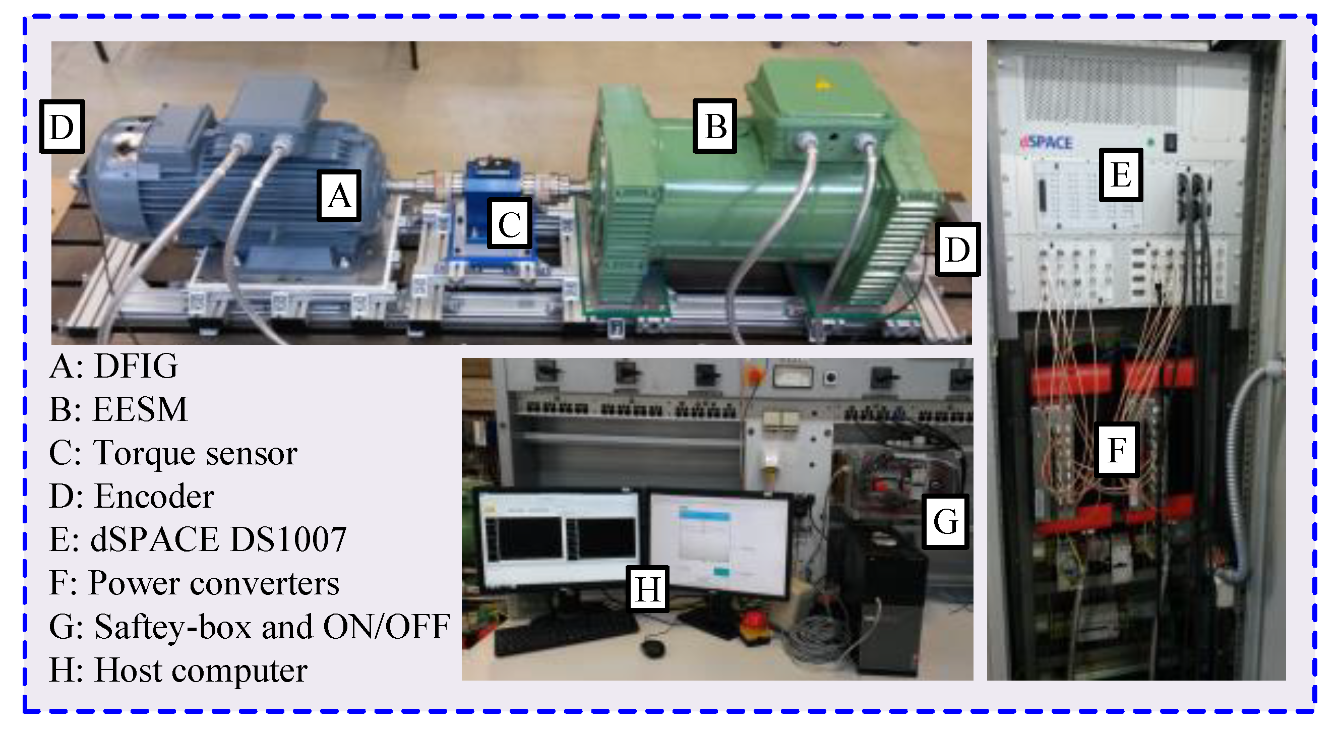
5. Description of the Test Bench

The utilized test bench to validate the presented LPS-MRAO is depicted in Figure 4, where a 10   k W DFIG is used in the following experiments. The basic parameters of this DFIG is listed in Table 1. In our laboratory, no wind turbine emulator is available. Therefore, another machine is used for this purpose, which is a 10   k W electrical-excited synchronous machine (EESM). As illustrated in Figure 1, the rotation speed of the rotor is controlled by the DFIG by using the non-linear criteria T e = k p ω m 2 . However, this controller is extremely slow. Therefore, in the following experiments, the EESM is used to regulate the rotation speed of the rotor. The used real-time system is a dSPACE DS1007 and the following boards are connected to it.
  • DS3002 incremental encoder board to interface the measured speed/position of the rotor with the main board. Note: this measured speed/position of the rotor is only for comparison with the estimated ones.
  • DS2004 analog to digital converter (A/D) board to interface the measured currents of the rotor and stator, measured voltages of the stator, and measured DC-link with the main board.
  • DS5101 pulse-width-modulation board to interface the switching signals with the power converters.

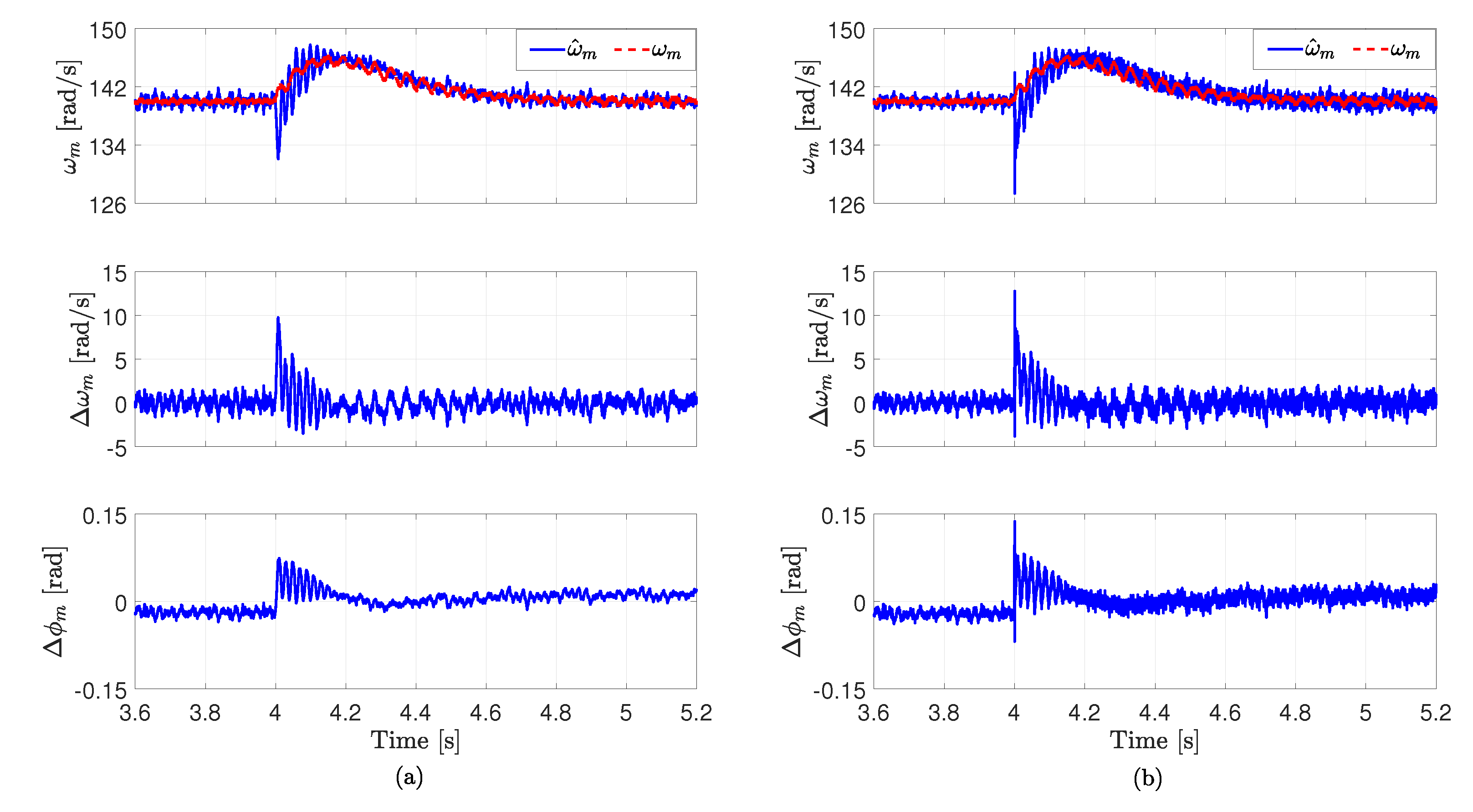
6. Experimental Results

The wind turbines-based DFIGs are operating with ± 30 % variations of the speed around the synchronous speed. In the adopted DFIG, the synchronous mechanical speed is 157   rad / s . If the rotation speed is lower than this value, the DFIG operates in the sub-synchronous region and if the rotation speed is higher than this value, the DFIG operates in the super-synchronous region.
In Figure 5, the mechanical rotation speed ω m of the DFIG rotor is ramped from 118   rad / s to 173   rad / s by the help of the EESM. In this experiment, the reference value of the electro-magnetic torque of the DFIG T e is selected 30   N m , while the reference value of the q-axis current of the DFIG rotor i r , r e f q is chosen 0 A . Based on Figure 5, the response of the presented LPS-MRAO in the transient conditions is better than the traditional MRAO, where the errors Δ ω m = ω m ω ^ m and Δ ϕ m = ϕ m ϕ ^ m are lower.
To further investigate and compare the dynamic performance of both proposed and conventional MRAO, a step change in the electro-magnetic torque of the DFIG T e from 35   N m to 20   N m is applied to the DFIG control strategy. The mechanical rotation of the DFIG rotor is regulated to be constant at 140   rad / s by the EESM. The experimental results at these operation conditions are illustrated in Figure 6. It can be clearly observed that the performance of the LPS-MRAO is better than that of the classical MRAO. By using the traditional MRAO, the overshoot in the estimated speed is approximately 15 rad / s , while an overshoot of 7   rad / s is seen in the response of the proposed LPS-MRAO. Furthermore, the errors Δ ω m = ω m ω ^ m and Δ ϕ m = ϕ m ϕ ^ m using the LPS-MRAO are lower than those of the conventional MRAO.
It is important to investigate the performance of the developed LPS-MRAO and traditional one under variations of the DFIG parameters. Accordingly, the stator resistance R s of the DFIG is reduced to half of its nominal value, i.e., R s = 0.5 R s o . Note: the change in the stator resistance of the DFIG occurred in the software model not in the hardware. The mechanical rotation of the DFIG rotor is regulated to be constant at 150   rad / s by the EESM and the electro-magnetic torque of the DFIG T e is controlled at 25   N m . Based on Figure 7, it is clear that variation of the stator resistance R s of the DFIG has almost no effect in the response of the developed LPS-MRAO and traditional MRAO. This is due to the fact that the value of the stator resistance R s of the DFIG is small, in particular for large generators like the ones used in real modern wind turbines.
The last experiment is to test the response of the developed LPS-MRAO and traditional one under variation of the stator inductance L s of the DFIG as illustrated in Figure 8, where L s is reduced by 50 % in the software model. The mechanical rotation of the DFIG rotor is regulated to be constant at 145   rad / s by the EESM and the electro-magnetic torque of the DFIG T e is controlled at 32   N m . It is clear that the robustness of the developed LPS-MRAO is better than that of the traditional MRAO. The dynamic error Δ ω m using the LPS-MRAO is approximately 6   rad / s , while it is approximately 19   rad / s using the traditional MRAO. Furthermore, the error Δ ϕ m using the classical MRAO is significantly higher than Δ ϕ m in case of using the developed LPS-MRAO.

7. Conclusions

In this paper, a limited-position set model-reference adaptive observer (LPS-MRAO) for sensor-less control of doubly-fed induction generators (DFIGs) in wind applications with variable-speeds has been developed. The fundamental idea of the developed LPS-MRAO is similar to the idea of the finite-set model predictive control (FS-MPC). This is because the rotor position of the DFIG is formulated as a limited number of angles, which is like the limited switching states of the power converter. The next step in the proposed LPS-MRAO is using this limited number of angles to observe a fixed number of values for the rotor current of the DFIG. After that, a cost function is designed to find the best position of the rotor in this limited number of positions, i.e., the position that gives the minimum error between the measured rotor current and observed one. Hence, the proportional-integral that is always utilized in the adaption mechanism of the classical MRAO is not needed. The developed LPS-MRAO and the traditional one have been implemented in the laboratory and the experimental results have been given and compared. Based on these results, it has been observed that the developed LPS-MRAO illustrated better dynamics and robustness than the classical MRAO.

Author Contributions

The developed observer is suggested, designed, and implemented by M.A. Furthermore, the writing—original draft preparation is realized also by M.A. Writing—review and editing, is realized by C.M.H. and R.K. Furthermore, the test bench to implement the developed observer is provided by C.H. All authors have read and agreed to the published version of the manuscript.

Funding

No external funding is received for this work.

Conflicts of Interest

No conflict of interest.

References

  1. United Nations. What Is the Paris Agreement? Available online: https://unfccc.int/process-and-meetings/the-paris-agreement/what-is-the-paris-agreement (accessed on 29 April 2019).
  2. Li, H.; Chen, Z. Overview of different wind generator systems and their comparisons. IET Renew. Power Gener. 2008, 2, 123–138. [Google Scholar] [CrossRef] [Green Version]
  3. Polinder, H.; Ferreira, J.A.; Jensen, B.B.; Abrahamsen, A.B.; Atallah, K.; McMahon, R.A. Trends in Wind Turbine Generator Systems. IEEE J. Emerg. Sel. Top. Power Electron. 2013, 1, 174–185. [Google Scholar] [CrossRef]
  4. Yaramasu, V.; Wu, B.; Sen, P.C.; Kouro, S.; Narimani, M. High-power wind energy conversion systems: State-of-the-art and emerging technologies. Proc. IEEE 2015, 103, 740–788. [Google Scholar] [CrossRef]
  5. Pena, R.; Clare, J.; Asher, G. Doubly fed induction generator using back-to-back PWM converters and its application to variable-speed wind-energy generation. IEE Proc. Electr. Power Appl. 1996, 143, 231–241. [Google Scholar] [CrossRef] [Green Version]
  6. Abad, G.; López, J.; Rodríguez, M.; Marroyo, L.; Iwanski, G. Doubly Fed Induction Machine: Modeling and Control for Wind Energy Generation Applications; Wiley: Hoboken, NJ, USA, 2011. [Google Scholar]
  7. Giaourakis, D.G.; Safacas, A.N. Effect of Short-Circuit Faults in the Back-to-Back Power Electronic Converter and Rotor Terminals on the Operational Behavior of the Doubly-Fed Induction Generator Wind Energy Conversion System. Machines 2015, 3, 2–26. [Google Scholar] [CrossRef] [Green Version]
  8. Cardenas, R.; Pena, R.; Alepuz, S.; Asher, G. Overview of Control Systems for the Operation of DFIGs in Wind Energy Applications. IEEE Trans. Ind. Electron. 2013, 60, 2776–2798. [Google Scholar] [CrossRef]
  9. Mwinyiwiwa, B.; Zhang, Y.; Shen, B.; Ooi, B. Rotor Position Phase-Locked Loop for Decoupled P-Q Control of DFIG for Wind Power Generation. IEEE Trans. Energy Convers. 2009, 24, 758–765. [Google Scholar] [CrossRef]
  10. Cardenas, R.; Pena, R.; Proboste, J.; Asher, G.; Clare, J. MRAS observer for sensorless control of standalone doubly fed induction generators. IEEE Trans. Energy Convers. 2005, 20, 710–718. [Google Scholar] [CrossRef]
  11. Cardenas, R.; Pena, R.; Clare, J.; Asher, G.; Proboste, J. MRAS observers for sensorless control of doubly-fed induction generators. IEEE Trans. Power Electron. 2008, 23, 1075–1084. [Google Scholar] [CrossRef]
  12. Abdelrahem, M.; Hackl, C.; Kennel, R. Encoderless Model Predictive Control of Doubly-Fed Induction Generators in Variable-Speed Wind Turbine Systems. J. Phys. Conf. Ser. 2016, 753, 1–10. [Google Scholar] [CrossRef] [Green Version]
  13. Lu, L.; Avila, N.F.; Chu, C.; Yeh, T. Model Reference Adaptive Back-Electromotive-Force Estimators for Sensorless Control of Grid-Connected DFIGs. IEEE Trans. Ind. Appl. 2018, 54, 1701–1711. [Google Scholar] [CrossRef]
  14. Abdelrahem, M.; Hackl, C.; Dal, M.; Kennel, R.; Rodriguez, J. Efficient Finite-Position-Set MRAS Observer for Encoder-less Control of DFIGs. In Proceedings of the IEEE International Symposium on Predictive Control of Electrical Drives and Power Electronics (PRECEDE), Quanzhou, China, 31 May–2 June 2019. [Google Scholar]
  15. Kumar, R.; Das, S.; Syam, P.; Chattopadhyay, A. Review on model reference adaptive system for sensorless vector control of induction motor drives. IET Electr. Power Appl. 2015, 9, 496–511. [Google Scholar] [CrossRef]
  16. Mbukani, M.W.K.; Gule, N. Comparison of high-order and second-order sliding mode observer based estimators for speed sensorless control of rotor-tied DFIG systems. IET Power Electron. 2019, 12, 3231–3241. [Google Scholar] [CrossRef]
  17. Abdelrahem, M.; Hackl, C.; Zhang, Z.; Kennel, R. Robust Predictive Control for Direct-Driven Surface-Mounted Permanent-Magnet Synchronous Generators Without Mechanical Sensors. IEEE Trans. Energy Convers. 2018, 33, 179–189. [Google Scholar] [CrossRef]
  18. Abdelrahem, M.; Hackl, C.; Kennel, R. Simplified Model Predictive Current Control without Mechanical Sensors for Variable-Speed Wind Energy Conversion Systems. Electr. Eng. 2017, 99, 367–377. [Google Scholar] [CrossRef]
  19. Abdelrahem, M.; Hackl, C.; Kennel, R. Sensorless Control of Doubly-Fed Induction Generators in Variable-Speed Wind Turbine Systems. In Proceedings of the 5th International Conference on Clean Electrical Power (ICCEP), Taormina, Italy, 16–18 June 2015; pp. 406–413. [Google Scholar]
  20. Azad, S.P.; Tate, J.E. Parameter estimation of doubly fed induction generator driven by wind turbine. In Proceedings of the IEEE/PES Power Systems Conference and Exposition, Phoenix, AZ, USA, 20–23 March 2011; pp. 1–8. [Google Scholar]
  21. Prajapat, G.P.; Bhui, P.; Kumar, P.; Varma, S. Estimation based Maximum Power Point Control of DFIG based Wind Turbine Systems. In Proceedings of the IEEE PES GTD Grand International Conference and Exposition Asia (GTD Asia), Bangkok, Thailand, 19–23 March 2019; pp. 673–678. [Google Scholar]
  22. Maiti, S.; Verma, V.; Chakraborty, C.; Hori, Y. An Adaptive Speed Sensorless Induction Motor Drive with Artificial Neural Network for Stability Enhancement. IEEE Trans. Ind. Inform. 2012, 8, 757–766. [Google Scholar] [CrossRef]
  23. Gadoue, S.M.; Giaouris, D.; Finch, J.W. MRAS Sensorless Vector Control of an Induction Motor Using New Sliding-Mode and Fuzzy-Logic Adaptation Mechanisms. IEEE Trans. Energy Convers. 2010, 25, 394–402. [Google Scholar] [CrossRef]
  24. Azza, H.B.; Zaidi, N.; Jemli, M.; Boussak, M. Development and Experimental Evaluation of a Sensorless Speed Control of SPIM Using Adaptive Sliding Mode-MRAS Strategy. IEEE J. Emerg. Sel. Top. Power Electron. 2014, 2, 319–328. [Google Scholar] [CrossRef]
  25. Rodriguez, J.; Pontt, J.; Silva, C.A.; Correa, P.; Lezana, P.; Cortés, P.; Ammann, U. Predictive Current Control of a Voltage Source Inverter. IEEE Trans. Ind. Electron. 2007, 54, 495–503. [Google Scholar] [CrossRef]
  26. Vazquez, S.; Leon, J.; Franquelo, L.; Rodriguez, J.; Young, H.; Marquez, A.; Zanchetta, P. Model Predictive Control: A Review of Its Applications in Power Electronics. IEEE Ind. Electron. Mag. 2014, 8, 16–31. [Google Scholar] [CrossRef]
  27. Abdelrahem, M.; Hackl, C.; Kennel, R.; Rodriguez, J. Efficient Direct-Model Predictive Control with Discrete-Time Integral Action for PMSGs. IEEE Trans. Energy Convers. 2019, 34, 1063–1072. [Google Scholar] [CrossRef]
  28. Abdelrahem, M.; Kennel, R. Efficient Direct Model Predictive Control for Doubly-Fed Induction Generators. Electr. Power Compon. Syst. 2017, 45, 574–587. [Google Scholar] [CrossRef]
  29. Abdelrahem, M.; Hackl, C.; Kennel, R. Finite set model predictive control with on-line parameter estimation for active frond-end converters. Electr. Eng. 2018, 100, 1497–1507. [Google Scholar] [CrossRef]
  30. Farhan, A.; Abdelrahem, M.; Hackl, C.M.; Kennel, R.; Shaltout, A.; Saleh, A. Advanced Strategy of Speed Predictive Control for Nonlinear Synchronous Reluctance Motors. Machines 2020, 8, 44. [Google Scholar] [CrossRef]
  31. Abdelrahem, M.; Rodríguez, J.; Kennel, R. Improved Direct Model Predictive Control for Grid-Connected Power Converters. Energies 2020, 13, 2597. [Google Scholar] [CrossRef]
  32. Zbede, Y.B.; Gadoue, S.M.; Atkinson, D.J. Model Predictive MRAS Estimator for Sensorless Induction Motor Drives. IEEE Trans. Ind. Electron. 2016, 63, 3511–3521. [Google Scholar] [CrossRef] [Green Version]
  33. Abdelrahem, M.; Hackl, C.; Kennel, R. Finite Position Set-Phase Locked Loop for Sensorless Control of Direct-Driven Permanent-Magnet Synchronous Generators. IEEE Trans. Power Electron. 2018, 33, 3097–3105. [Google Scholar] [CrossRef]
  34. Abdelrahem, M.; Hackl, C.M.; Rodríguez, J.; Kennel, R. Model Reference Adaptive System with Finite-Set for Encoderless Control of PMSGs in Micro-Grid Systems. Energies 2020, 13, 4844. [Google Scholar] [CrossRef]
Figure 1. Schematic-diagram of the VOC technique for doubly-fed induction generators (DFIGs) with model-reference adaptive observer (MRAO) in wind turbine systems.
Machines 08 00072 g001
Figure 2. Block diagram of the traditional MRAO for control of DFIGs without incremental encoders.
Machines 08 00072 g002
Figure 3. Block diagram of the proposed limited-position set (LPS)-MRAO for control of DFIGs without mechanical sensors.
Machines 08 00072 g003
Figure 4. The used test bench to validate the proposed LPS-MRAO.
Machines 08 00072 g004
Figure 5. Experimental results at changes of the rotation speed of the rotor: (a) LPS-MRAO, and (b) traditional MRAO.
Machines 08 00072 g005
Figure 6. Experimental results at variations of the electro-magnetic torque of the DFIG T e : (a) LPS-MRAO, and (b) traditional MRAO.
Machines 08 00072 g006
Figure 7. Experimental results at variations of the DFIG stator resistance R s : (a) LPS-MRAO, and (b) traditional MRAO.
Machines 08 00072 g007
Figure 8. Experimental results at variations of the DFIG stator inductance L s : (a) LPS-MRAO, and (b) traditional MRAO.
Machines 08 00072 g008
Table 1. Parameters of the utilized DFIG.
Name of the SignalMath. SymbolValue
Nominal power p n 10   k W
Nominal line-line voltage of the stator u s , n 400   V
Voltage of the DC-link u d c 360   V
Nominal mechanical angular speed ω m , n 157   rad / s
Stator resistance R s 0.72   Ω
Rotor resistance R r 0.55   Ω
Stator inductance L s 73.5   m H
Rotor inductance L r 86   m H
Mutual inductance L m 60   m H
Pole pairs n p 2
Publisher’s Note: MDPI stays neutral with regard to jurisdictional claims in published maps and institutional affiliations.

