Article

Calculating Power Parameters of Rolling Mill Based on Model of Deformation Zone with Four-Roll Passes

by
Marina N. Samodurova
1,
Olga I. Karandaeva
2,
Vadim R. Khramshin
3,* and
Ivan V. Liubimov
2
1
Department of Metal Forming, South Ural State University, 454080 Chelyabinsk, Russia
2
Department of Mechatronics and Automation, South Ural State University, 454080 Chelyabinsk, Russia
3
Department of Electric Power Supply of Industrial Enterprises, Nosov Magnitogorsk State Technical University, 455000 Magnitogorsk, Russia
*
Author to whom correspondence should be addressed.
Machines 2020, 8(4), 73; https://doi.org/10.3390/machines8040073
Submission received: 29 September 2020 / Revised: 3 November 2020 / Accepted: 11 November 2020 / Published: 13 November 2020
(This article belongs to the Special Issue Selected Papers from the ICIEAM 2020 Conference)

Abstract

:
Making “digital twins” for rolling processes and mill equipment should begin with the development of mathematical models of the deformation zone. The deformation zone of two-high flat mill rolling have been studied in detail, relevant models are available in many academic papers. However, the same cannot be said about the most complex deformation zones in stands with multi-roll gauge. Therefore, the task of their reliable mathematical description is of immediate interest. The development of mathematical models is necessary for the design of new wire mills and rolling-drawing units. The combination of rolling in stands with multi-roll gauge and drawing is a promising direction in the production of wire from difficult-to-form steels and alloys. Digital models for pressure-based metal treatment are also necessary for calculating the rolling-mill power parameters during the development of new assortments at the operating mills. The models of deformation zones present the basis for developing the multivariable control systems of process conditions of continuous mills. This research is devoted to the study of the deformation zone and the development of a procedure for calculating the power parameters of rolling in a stand with four-roll passes. The solution of these challenges is given using the example of an operating five-stand wire mill. The authors analysed the known analytical dependencies for calculating the rolling mill force and torque. A mathematical model of the deformation zone and a program for calculating the power parameters have been developed. The paper compares the results obtained from calculations based on analytical dependence and on modelling. A comparison with the experimental parameters obtained at the mill is given. The authors assess the feasibility of using the known formulas and analyse the impact of the front and rear tensions on the power parameters of rolling mill. The problem of developing an automatic tension control system for continuous mills with multi-roll groove is substantiated.

1. Introduction

Rolling mills for the production of steel wire are classified according to the number of mill-stand rolls, which form the geometry of the deformation zone. Accordingly, these can be categorised by the type of roll groove and the roll transmission path. It is customary to refer to a groove formed by three or more rolls with the axes in the same vertical plane (Figure 1), as a multi-roll. Such a composition provides for a high dimensional precision of the manufactured profile. Therefore, modern small-section and wire mills for rolling steel and non-ferrous metals are designed using finishing mill groups of stands with multi-roll groove.
The most common grooves are: triangular, formed by three smooth rolls; rectangular, formed by four rolls, Figure 1a; hexagonal, formed by six smooth rolls or three grooved rolls, and so on. These are used in different configurations, building complex systems (for example, triangle–triangle), Figure 1b [1,2].
The conditions for metal deformation in a multi-roll groove have advantages over the conditions for deformation in a groove formed by two rolls. Indeed, two-rolls flat rolling usually results in an increase in the length of the roll (draw-down) and its widening (spreading effect). At the same time, rolling in a multi-roll groove is characterized by simultaneous height/width drafting of the roll and a significant draw-down. The principal stress diagrams for the deformation of both types remain the same, the difference is only in values thereof. In multi-roll groove, the height-transverse drafting is a positive factor that provides for rolling low-ductility alloys, which is crucial.
Unlike the rolling in two-roll groove, free forging or rotary swaging, drafting of stock material in multi-roll grooves involves three or four sides, rather than two. Moreover, during stretch rolling, for example, a square-shaped stock material is set for a square groove in the “edgeways” position (Figure 1a) [3]. Multi-sided compression with a varied-width deformation zone leads to the following features:
  • In the deformation zone, a pattern of all-round compression of the workpiece at high hydrostatic pressure is created, which increases the plasticity of the processed material, also providing for better one-time deformations;
  • The pattern of the deformed state is changing, which makes it possible to eliminate the crossflow of the material, for better one-time deformations, in order to increase one-time draw-downs;
  • Intensive all-round compression of the workpiece leads to a higher density, better physical and mechanical properties and structure of the product.
Figure 1b shows a diagram of longitudinal rolling of metal in a stand with two three-roll grooves, which form the most closely spaced deformation zones in the driven rolls 1–6 [4]. Longitudinal rolling of the round workpiece 7 is carried out to obtain, for example, the hexagonal metal profile 8.
Multi-roll grooves in comparison with two-roll grooves provide for a better rigidity of the stands, and, consequently, a better dimensional precision of rolled products, lower spreading effect and higher drawing capacity of the stand. In addition, the strain pattern in the deformation zone can be easily changed, bringing it closer to all-round compression. This provides favourable conditions for increasing the partial and total drafting [5]. Therefore, the number of rolling stands in the mill line is almost halved in comparison with two-high rolling and drawing in roller dies [6].
The three-roll milling process in two-groove stands (Figure 1b) is a vital technology for the production of round bars and hexagonal sections used in construction. It provides better mechanical properties of profiles due to large structural yielding [7]. Publications [4,8,9] are devoted to the study of such modes. They investigate the processes of symmetric and asymmetric rolling. The analysis of metal deformation was performed using the DEFORM-3D software. The key results are the substantiation of the drafting patterns and recommendations for the practical use of stands in processing lines of combined rolling-drawing units.
A significant drawback of stands with three-roll grooves is the low load capacity in terms of rolling force and torque supplied to the rolls. This reduces the deformation value of the workpiece in each stand and limits the options for rolling materials with high resistance to deformation [2]. Therefore, rolling stands with four-roll pass have found the greatest practical application.
The first information about a universal mill where the four-roll pass included two horizontal driven and two vertical non-driven rolls, dates back to 1854 [10]. The scientists from the Chelyabinsk Polytechnic Institute (currently South-Ural State University, Russia) were the first to develop stand designs for universal section mills containing replaceable cassettes with three- and four-roll grooves [11,12]. A special feature of these stands was that the work rolls are rotated from contact with two driven backup rolls. At the end of the 1970s, such universal mills began to operate at the Izhstal enterprise (Izhevsk city). Stands of a similar design have been developed by the Research Institute of Metallurgical Engineering (VNIImetmash).
Over the past decades, there have been significant changes in the design of stands and technological schemes for rolling, as well as in drafting modes. Significant experience has been accumulated in operating mills that were manufactured at various metallurgical plants. Constantly growing market requirements for metal goods and products dictate the need to expand the range of rolled assortment.
One of the successfully operated units is a five-stand wire mill with four-roll grooves built at the Beloretsk Metallurgical Plant [13]. Currently, its owners explore the possibility of producing the wire rod with over 8 mm thickness, which is outside the design parameters of the rolling mill. This predetermines the need to improve the methodology for calculating the rolling force, the shaft torque and the power of the actuating unit. Such studies would make it possible, firstly, to assess the possibilities of expanding the product range, and secondly, to determine the limits imposed by the electric drive on the technological process.
In addition to determining the power parameters, the improvement of their calculation methods will provide an opportunity to simulate the rolling process on promising multi-stand mills, taking into account the interaction of electromechanical systems through the metal [14]. This challenge cannot be solved by using well-known software packages based on finite-element models (DEFORM, ABAQUS, ANSYS, Q-FORM, etc.), since it requires runtime assessment of multivariable systems.
The calculation of electric and force parameters is relevant either for the construction of new mills or at the extension of the rolled product range of the existing ones. The analysis of stand force interaction is important for improving automated electric drives and the systems of automatic technological parameters control.
Modern stand design procedures are based on the accumulated experience of using various groove systems. They solve the problem of obtaining the required precision, the stable continuous rolling process, and the required drawing capacity [15]. This determines the relevance of returning to the formation of mathematical models of deformation zones in stands with multi-roll grooves.

2. Problem Formulation

2.1. Study Object Properties

The object of research is the aforementioned five-stand wire mill with four-roll passes. The mechanical units of this mill were manufactured by SKET (Magdeburg, Germany). It is designed for rolling process wire of 2.5–3.5 mm diameter using 6.5–8.0 mm diameter initial wire rod. Electric drives and control systems have been developed by experts from the Magnitogorsk Mining and Metallurgical Institute (currently, the Magnitogorsk State Technical University).
The layout of the equipment is shown in Figure 2 [13]. The stands are divided into roughing (with tension roll passes) and finishing (with finishing passes). The main work on total deformation of the metal is carried out in the tension roll passes, while the finishing passes are used to form the geometry and size of the finished profile. Table 1 shows options for four-roll passes rolled on the mill.
The rolled stock is fed from a reel or a coil. There is a welding device for welding the ends of the wire rod during continuous rolling. The Wire Accumulator 5 eliminates shock loads on the decoiler if the turns get overlapped. If necessary, the High-Frequency Inductor 6 can heat the stock material to temperatures of warm rolling.
Constant change of angles during the transition from groove to groove, and extra heating due to intense deformations, create a favourable temperature distribution over the metal section, providing high quality of wire surface and microstructure [5,16]. It is also an advantage that an operator can feed stock material with different cross-sections into the same grooves. This ensures that a finished profile has the target size at different values of the total draw-down. This property demonstrates a great flexibility of four-roll pass compared to two- and three-roll grooves.
This study is devoted to the analysis of the calculated and experimental rolling forces (rolling pressure of the metal). The paper analyses the results of calculating the mill torque according to the earlier developed analytical dependencies. The results of comparison with similar values obtained in the course of modelling are presented. The conclusions of these studies can be applied to any units where production lines include stands with multi-roll grooves.

2.2. Rationale for Model Development

The main task of rolling on industrial mills is to obtain a required product profile using minimum operations. At the same time, high productivity provision is also vital. Little attention is paid to equipment loads, metal temperature distribution, friction conditions, and other process parameters. Typically, in complex stands, the desired shape change is achieved by trial and error.
On the basis of the energy theory of the interaction of rolled stock and rolls, scientists of Chelyabinsk Polytechnic Institute under the guidance of Professor Vydrin V.N. developed methods for calculating the kinematic and power parameters for pressure-based metal processing in the studied stands. Technological processes have been developed for the grooving of round sections, the production of high-precision shaped profiles, and the hot rolling of low-ductility alloys in stands with four-roll passes [17,18].
The study of the stressed state of metal in complex deformation zones is covered in the work of Professor Kharitonov V.A. (Magnitogorsk State Technical University) [15,19,20]. In the research, the Professor used the Finite Element method implemented in the DEFORM-3D software package. In addition, this software was used to study the processes of wire rolling and drawing in the research [21,22]. It has been established that the combined method of rolling and drawing provides for a comprehensive processing of the wire cross section. This is because the monolithic die usually processes the surface layers, while the roller die processes the inner layers of the roll material.
Most experts agree that further improvement in wire rolling will be achieved through process control, as happened in sheet rolling production. This development would require the elaboration of budget-friendly high-precision models that can operate autonomously. The speed required for analysing the dynamics of the process indicates that relatively simple models for calculating the technological rolling mill parameters are needed as much as complex finite-element models. In essence, they should be the digital twins developed with due consideration to the results of empirical research. This task is of immediate interest due to the expanding assortment of mills with multi-roll grooves.

3. Materials and Methods

As it has been mentioned in Section 1, the research presented in the article, should provide solutions for the following problems:
  • Improvement of the method applied to calculate the metal rolling pressure, moment and power of the drive motor.
  • Making up a methodological base to simulate the rolling process at promising multi-stand mills, taking into account the electromechanical system interaction via metal.
To solve these problems, one does not have to conduct a detailed study of metal flow in axial directions and, correspondingly, to solve a 3D problem. That is why it is reasonable to apply one-dimensional model, based on the known dependences of rolling pressure and mill torque calculation.
Currently, several dependences are known for determining the mill torque in stands with multi-roll grooves [6,23,24,25,26]. Some of them are obtained for specific cases, others are more general. In this connection, there was a task of comparative analysis of dependencies in order to determine the most suitable parameters for continuous wire mills. They were developed under the following assumptions [6]:
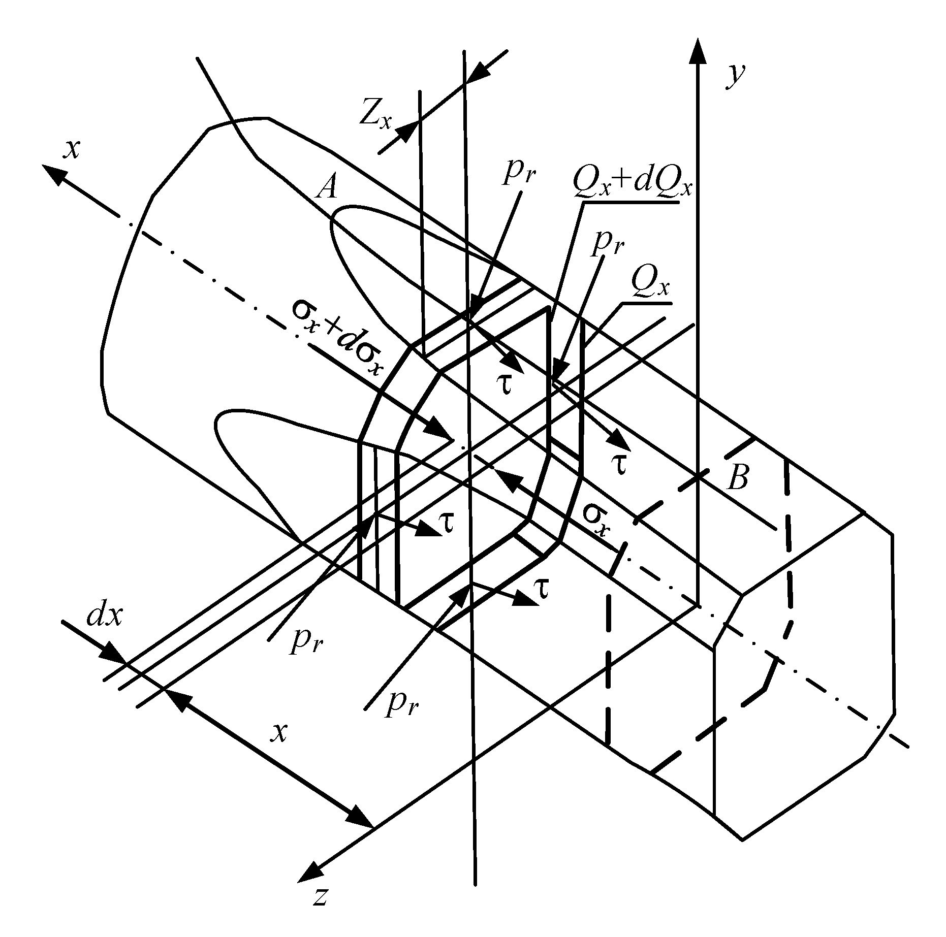
  • The hypothesis of plane sections, experimentally confirmed by many studies, is accepted as a working hypothesis.
  • The relationship between normal and shear stresses is described either by the Amonton–Coulomb dry friction law or by Siebel’s law.
  • The hardening curve is approximated as a straight line.
  • The friction coefficient along the contact arc is considered constant.
  • The distribution of specific pressure over the groove width is assumed to be uniform.
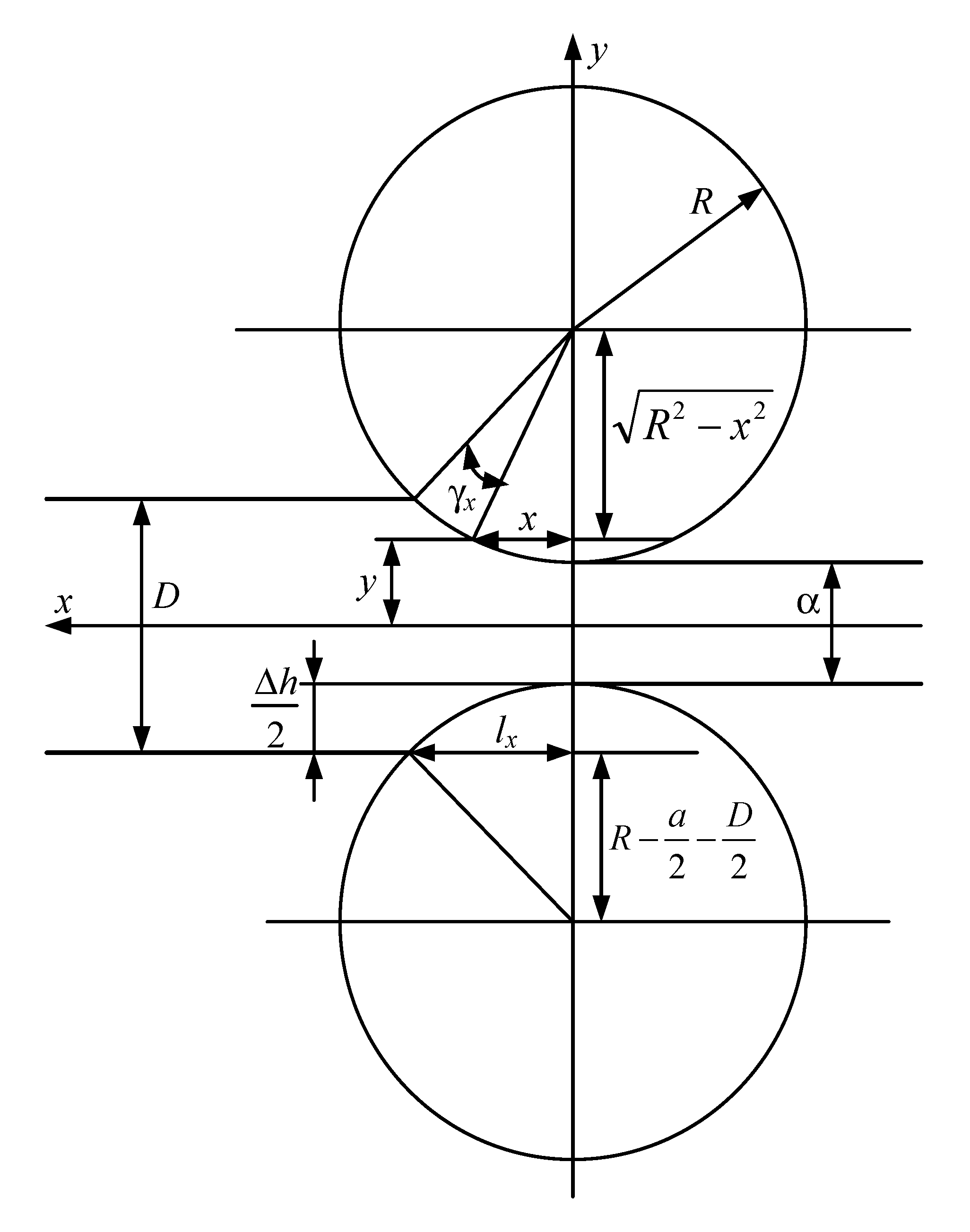
  • The contact arc is replaced by a chord.
The metal hardening curve along the deformation zone is complex, and it is difficult to consider in practical calculations [27,28]. At the calculation of rolling energy and force parameters, the dependence can be linearized. That is why at the derivation of the Equation (1), the hardening along the deformation zone is assumed to be linear [6]. Essentially, this dependence is a linear hardening kinematic model. Such dependences are obtained by the authors at the rolling of various profiles in laboratory conditions and at the existing rolling mill.
These assumptions helped to obtain an equation for determining the average specific rolling pressure of the metal, based on the condition of the equilibrium of forces acting on the elementary volume in the deformation zone [6]:
P = Q 0 n f Q c a { [ δ ( σ y f σ 0 ) + ( m σ y 0 ) ] ( μ γ 1 ) δ 1 m σ y 0 μ [ μ + + 1 2 μ μ γ ] + [ δ ( σ y f σ 1 ) ( m σ y 0 ) ] [ ( μ μ γ ) ( δ + 1 ) 1 ] μ ( δ 1 )
where
δ = f · c t g ( α / 2 ) coefficient ;
n —number of rolls in the groove; f —friction coefficient; α = arccos ( 1 Δ h / 2 R ) —entering angle; R —roll radius; Δ h —absolute drafting; σ y 0 , σ y f —initial and final values of the yield point; the value σ y f depends on the drafting and can be found using the experimental curves given in [16]; μ = Q 0 / Q 1 —draw-down extraction; Q 0 , Q 1 —section of the stock material before and after drafting; σ 0 = F 0 / Q 0 , σ 1 = F 1 / Q 1 —specific rear and front tensions; F 0 , F 1 —rear and front tension; m = σ y f σ y 0 μ 1 —hardening module; Q c a —rolls’ contact area, for a circle–square diagram:
Q c a 0 , 8 h 1 R Δ h
h 1 —strip height at the stand exit; μ γ —drawing-down in neutral section.
Equation (1) was obtained by the monograph [6] authors for rolling at four-roll pass with all driven rolls at uniform drafting from all sides. As a working hypothesis, a plane section hypothesis is taken. Its truth is proved by the results of the research on the regularities of shape changing at the round billet (20 mm+ in diameter) deformation. Even at the increased diameter (up to 50 mm), the deformation of cross-sections is small. The friction coefficient in the arc of contact is taken as constant while the specific pressure distribution along the pass width is taken as uniform.
The cross-section area of the original workpiece Q 0 depends on its shape; the cross-section Q 1 at the roll exit depends on the shape of the groove.
To find μ γ in [6], the recommended equation is
μ γ = { 1 + 1 + μ δ [ 1 + ε ( σ y 0 σ 0 ) m σ y 0 ] [ δ ( σ y f σ 1 ) m σ y 0 ] 1 + δ ( σ y 0 σ 0 ) m σ y 0 } 1 / δ
where ε —relative deformation of the metal; the dependence for its calculation is provided below in the explanation of the Equation (16).
It should be noted that with ( m σ y 0 ) < 0 (when rolling in the second, third and subsequent stands), this Equation is unsolvable. Therefore, it is advisable to use the Equation
μ γ = ( A / C + ( A / C ) 2 + B / C ) 1 / δ
where A = ( m σ y 0 ) / δ ; B = μ δ ( σ y f σ 1 A ) ; C = ( σ y 0 σ 0 ) + A .
The authors of [6] recommend obtaining the rolling moment for the case of all driven rolls according to the dependence
M = R Q 0 { δ ( σ y 0 σ 0 ) + ( m σ y 0 ) δ 1 ( μ γ ( δ 1 ) 1 ) δ ( σ y f σ 1 ) + ( m σ y 0 ) μ ( δ + 1 ) [ ( μ μ γ ) ( δ + 1 ) ] ( m σ y 0 ) ( μ 1 ) μ }
where l = R Δ h —contact arc length.
The authors of the publication [6] also obtained the dependence similar to the Equation (1), however, applicable at the hardening curve approximation by the second order dependence (parabola). The following Equations are recommended to use for its derivation:
  • for drawing-down in neutral section
    μ γ = 2 r cos ( π 3 + ϕ 3 ) b 3 a
    where a = 2 δ ( σ m 1 μ 2 ) / 3 ; b = δ [ 3 ( σ m 1 μ 2 ) + m 1 ] ; ϕ = arccos ( q / r 3 ) ; r = ± | ρ | ; q = ( b 3 / 27 a 3 ) ( b c / 6 a 2 ) + ( d / 2 a ) ; ρ = ( 3 a c b 2 ) / 9 a 2 ; c = 4 m 1 δ μ + 6 δ ( σ y f m 1 μ 2 ) ; d = { σ 0 σ 1 + m 1 ( μ 1 ) 2 + 2 m 1 δ μ ( μ + 1 ) + [ m 1 ( μ 2 1 ) / 2 ] [ m 1 δ ( μ 2 1 ) / 2 + ( σ y f m 1 μ 2 ) [ ( δ + 1 ) ln μ + 11 δ / 3 ] } ; m 1 = ( σ y f σ y 0 ) / ( μ 1 ) 2 —hardening module; r —co-sign coefficient of q ; δ —coefficient given by Equation (2).
  • for calculating the average specific pressure of the metal on the rolls
    P a p = μ { m 1 [ 1 + δ μ ( 1 δ ) 2 δ μ γ ] / 2 ( σ y f m 1 μ 2 ) [ 1 δ ( 1 + δ ) ( 1 + ln μ ) / μ + 2 δ ( 1 + ln μ γ ) / μ γ + 2 m 1 δ μ ( 2 ln μ γ ln μ ) + C 0 ( μ γ 1 ) / μ γ + C 1 ( μ μ γ ) / ( μ μ γ ) } / ( μ 1 )
    where C 0 , C 1 —integration constants: C 0 = σ y 0 σ 0 + m 1 ( 1 + δ ) / 2 2 m 1 δ μ ;
    C 1 = σ y f σ 1 + ( m 1 μ 2 + 3 m 1 δ μ 2 ) + ( σ y f m 1 μ 2 ) ( 1 + δ ) ln μ
  • for mill torque
    M = n f R Q c a μ { ( σ y f m 1 μ 2 ) [ 1 + ( 1 / μ ) ( 2 / μ γ ) ] + 2 m 1 μ ( 2 l μ γ + ln μ ) + m 1 ( μ 2 μ γ + 1 ) } / ( μ 1 )
    When deriving Equations (6)–(8), Siebel’s law of friction was used. Metal forward slip in the deformation zone:
    s = ( μ · cos γ / μ γ ) 1 ( μ / μ γ ) 1
    The research in [24,25,26] studied the deformation zone using the energy conservation law and the least energy law. For the mill torque in multi-roll groove with all driven rolls, the following equations are obtained
    M = R { [ n ( μ 1 ) P a p f Q c a / ( μ + 1 ) ] + Q 1 σ a y ln μ Q 1 σ 1 + Q 0 σ 0 }
    M = R { [ n ( μ 1 ) σ a y f Q c a / ( μ + 1 ) ] + Q 1 σ a y ln μ Q 1 σ 1 + Q 0 σ 0 }
    where σ a y = ( σ y f + σ y 0 ) / 2 —average value of the yield point.
Obviously, the results obtained by applying the given formulas may differ significantly from each other and from the true values. However, the necessary analysis of the calculations accuracy has not yet been carried out. There are no recommendations in the literature on the preference of this or that dependency. Therefore, such an analysis is of immediate interest. To solve this challenge, one needs to know the reference parameters—using these for comparison would provide an opportunity to assess the accuracy of calculations. Such parameters are the results of the experiment. However, conducting a series of experiments for various grooves, profiles and rolling conditions is a difficult task. Therefore, the rational way is mathematical modelling. The use of methods of numerical integration provides more accurate application of the dynamic parameters of the deformation zone in comparison with calculations using analytical expressions. These will provide for consideration of the relationships and satisfactory precision of the results, while being less “science intensive” in comparison with the finite-element models in the DEFORM-3D package and others.

4. Implementation

4.1. Digital Model for Deformation Zone of Stand with Four-Roll Pass

For the elementary volume of the deformation zone (Figure 3), the equation of contact stresses is written in the form [13]
σ x · Q x ( σ x d σ x ) · ( Q x d Q x ) + 8 · p r · Z x · t g ( α x ) · d x ± 8 · τ · Z x · d x = 0
where p r , τ—normal (radial) and shear stress; Q x —cross-sectional area of metal with coordinate x; Z x —half the width of the metal contact with roll in the cross-section with the coordinate x; α x —angle, defining the position of the cross-section with the coordinate x; σ x —axial stress.
The “+” sign refers to the forward slip zone, the “−” sign to the backward slip zone.
To obtain the differential equation of contact stresses, it is advisable to use the hypothesis of plane sections and the plasticity equation in the form
( σ 1 σ 2 ) 2 + ( σ 2 σ 3 ) 2 + ( σ 3 σ 1 ) 2 = 2 · σ d r
where σ d r —deformation resistance; σ 1 , σ 2 , σ 3 —principal stresses.
Further, for a symmetrical four-roll pass with all-driven rolls, in case of equal drafting by vertical and horizontal rolls and with small entering angle, the following equations are valid
σ 2 = σ 3 p r ;   σ 1 = p r σ d r
d σ 1 d x = d p r d x d σ x d x
Taking into account Equations (12)–(14), Equation (11) takes the form
d p r d x = p r · ( 8 · Z x · t g ( α x ) d Q x d x ) ± 8 · τ · Z x + d σ d r d x · ( Q x + d Q x ) + d Q x d x · σ d r Q x d Q x
The resulting equation serves as the basis for mathematical description of the deformation zone. Notably, its derivation did not take into account the tightening and spreading effect in the direction of the groove diagonal axis, or the inertial force arising from the accelerated motion of the elementary volume along the deformation zone, due to insignificance thereof [29].
The initial conditions are determined by the plasticity equations
p r A = σ d r 0 σ A ;   p r B = σ d r 1 σ B
where σ d r 0 , σ d r 1 —the values of deformation resistance at the beginning and at the end of the contact arc (Figure 4); σ A , σ B —stresses from tension forces at points A and B of the contact arc.
The relationship between tangential and normal stresses is described by the dry friction law
τ = f · p r
where f —friction coefficient.
It is expedient to solve the differential Equation (15) according to the following algorithm. Normal stresses in the backward p r , b a c k and forward p r , f o r w slip zones are calculated with the step Δ x . In the backward slip zone, the coordinate x 0 is determined by the equation
x 0 = l x x 1
where l x —contact arc projection on x axis; x 1 x coordinate in the forward slip zone.
Comparison is performed at each step, p r , f o r w and p r , b a c k . If p r , b a c k < p r , f o r w , the calculation in the next step is carried out for the backward slip zone, if p r , b a c k > p r , f o r w —for the forward slip zone. As a result, a successive approximation to the neutral section is performed (in the neutral section the values of the normal stresses are maximum).
The pressure on the rolls and the mill torque are found by the Equations
P = 2 · [ m = 1 k p e f , b a c k + n = 1 υ p e f , f o r w ] ;   M = 8 · [ m = 1 k M e t , b a c k + n = 1 υ M e t , f o r w ]
where k , υ —the number of steps in the algorithm for backward and forward slip zones; M e t , b a c k , M e t , f o r w —elementary torque acting on a site with dimensions Δ x and Z x :
in the backward slip zone
M e t , b a c k = f · Δ x · Z x · R · p r , b a c k c o s ( α b a c k )
in the forward slip zone
M e t , f o r w = f · Δ x · Z x · R · p r , f o r w c o s α , f o r w
where p e f , b a c k , p e f , f o r w —elementary forces applied to the site Δ x · Z x :
in the backward slip zone
p e f , b a c k = Δ x · Z x · p r , b a c k · [ 1 f · t g ( α b a c k ) ]
in the forward slip zone
p e f , f o r w = Δ x · Z x · p r , f o r w · [ 1 + f · t g ( α f o r w ) ]
b a c k , f o r w —indexes of lags in backward and forward slip zones.
The average specific pressure of the metal on the rolls is determined by the equation
P a p = p / Q c a
where Q c a = 1 k + υ 2 · Δ x · Z x Q c a —horizontal projection of the roll/metal contact area.
The value of the deformation resistance, taking into account the work-hardening of the metal [16]:
σ d r = σ s + α σ · ε β
where α , β —empirical coefficients; σ s —deformation resistance; ε = Q c s a Q x Q c s a · 100 % ; Q c s a —original cross-sectional area of wire rod.
According to Equation (16), the derivative d σ d r / d x : d σ d r d x = 100 · α σ · β ε ( β 1 ) 1 Q c s a · d Q x d x .
The equation for the forward slip in the deformation zone can be obtained using the equality of per-second volume passing through any section of the deformation zone
s = Q γ Q 1 · cos γ 1
where Q γ , γ —neutral area and angle.
The definition of the contact arc projection l x , as well as the values Z x , t g α x , d Q x / d x , Q x , included in Equation (15), depends on the shape of the grooves formed by the rolls. Below, the authors consider the procedures for determining the calculation formulas using the example of the “circle—incomplete square” groove.

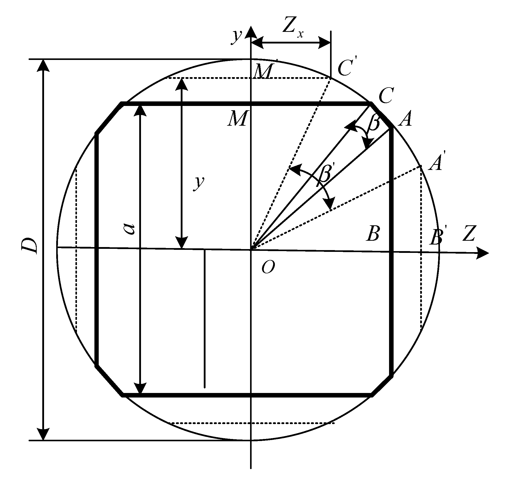
4.2. Groove System “Circle—Incomplete Square” (First Stand)

The original wire rod diameter is indicated by D ; the square output size is indicated by a (Figure 4 and Figure 5). Contact arc projection l x and t g α x are defined by equations
l x = R 2 ( R + a 2 D 2 ) 2 ;   t g α x = x R 2 x 2
They are derived from the geometric relationships that are explained by the above figures.
Equations for Q x and Z x are derived according to Figure 5. The cross-sectional area at the deformation zone entry ( x = l x ) is equal to the cross-sectional area of the wire rod
Q c s a = Q 0 = π · D 2 4
Area of output cross-section at x = 0 :
Q 1 = 4 · ( Q Δ A O B + Q Δ M O C + Q c e k C O A )
The areas of the triangles AOB and MOC are equal and determined by the equation
Q Δ A O B = 1 2 · O B · A B = 1 8 · a · D 2 a 2
Area of the COA sector:
Q c e k C O A = β D 2 8 = D 2 16 ( π 4   arccos a D )
where
β = π 2 2 · arccos O B O A = 1 2 · ( π 4 · arccos a / 2 D / 2 )
Taking into account Equations (18) and (19), Equation (17) takes the form:
Q 1 = a · D 2 a 2 + D 2 4 · ( π 4 · arccos a D )
Cross-section Q x with coordinate x ( 0 < x < l x ) is shown in Figure 5 by dotted lines. Its area is determined by the dependency
Q x = 4 · ( Q Δ A O B + Q Δ M O c + Q c e k C O A ) = 4 · y · D 2 4 y 2 + D 2 4 · ( π 4 · arccos 2 y D )
where y —coordinate of the point M (Figure 5) on the plane of metal contact with the rolls (Figure 4):
y = R + a 2 R 2 x 2
Half the width of the contact plane Z x (Figure 5):
Z x = D 2 4 y 2
After differentiation of Equation (20) with respect to x and transformations, the following equation is obtained
d Q x d x = 8 · x · D 2 4 y 2 R 2 x 2
The above Equations are used to find the desired values for calculating the specific pressure according to dependency (15).
Similar results were obtained for the groove systems “incomplete square—irregular octagon” (second stand), “irregular octagon—irregular octagon” (third stand).

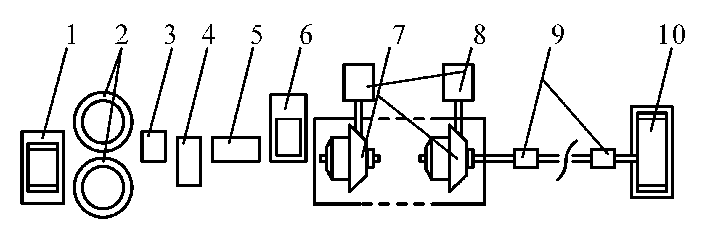
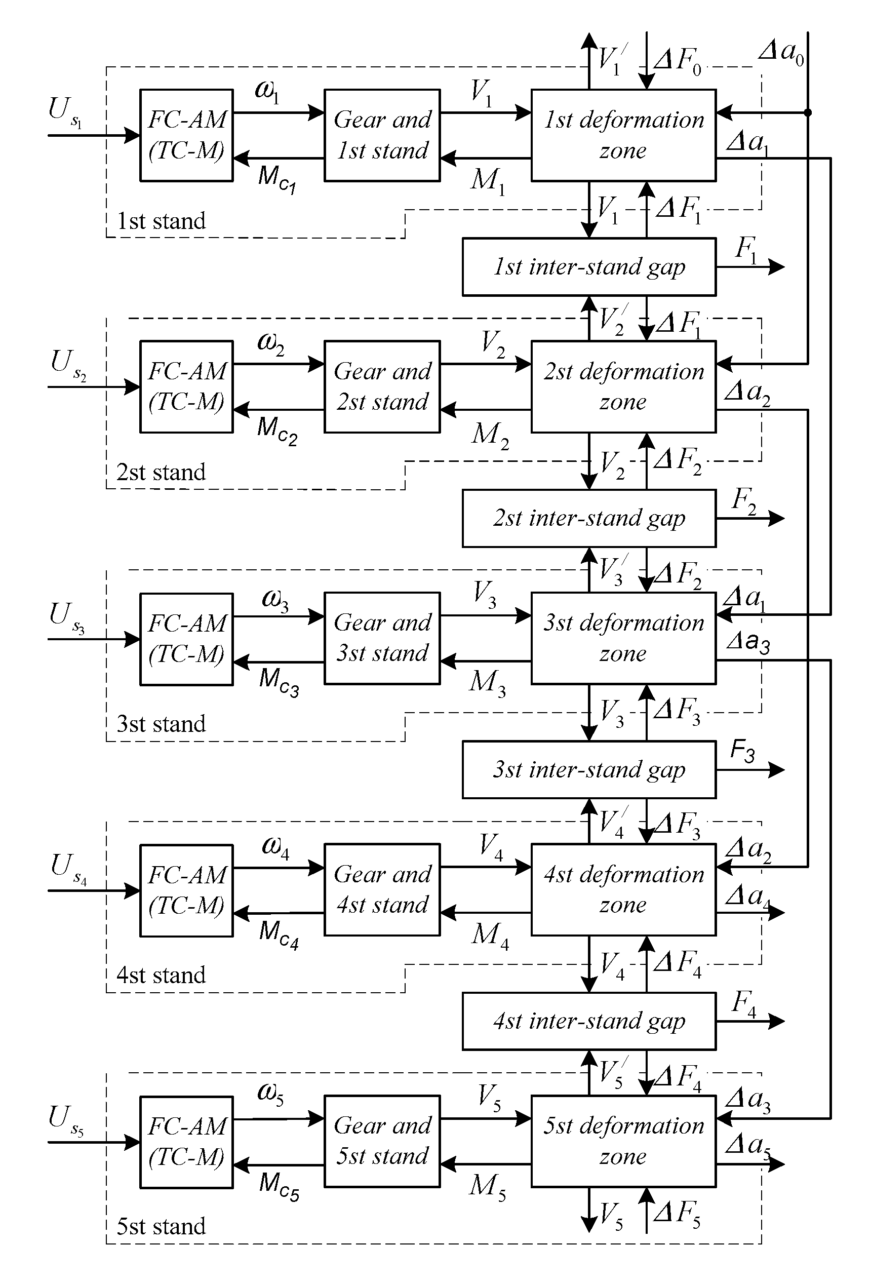
4.3. Structure of a Digital Model for a Five-Stand Mill

Figure 6 provides a generalized structural diagram of the developed five-stand mill model shown in Figure 1 [14]. The considered above mathematical description makes it possible to establish the interconnection between metal rolling pressure P, mill torque M and metal forward slip in the deformation zone s in the form of complex non-linear functions of input and output sizes of the strip D and α, friction coefficient f, the yield strength of the initial billet σS, forward and back tension values F1, F0
P i = f 1 ( D i , α i , f i , σ s , i , F 0 , i , F 1 , i ) M i = f 2 ( D i , α i , f i , σ s , i , F 0 , i , F 1 , i ) s i = f 3 ( D i , α i , f i , σ s , i , F 0 , i , F 1 , i ) }
For the purpose of linearization of these equations in the operational range of coordinate change, the authors transit from the absolute values Pi, Mi, si to their increments. In this case, the system (21) takes the form
Δ P i = c 1 , i · Δ D i + c 2 , i · f i + c 3 , i · Δ σ s , i + c 4 , i · Δ F 0 , i + c 5 , i · Δ F 1 , i Δ M i = c 6 , i · Δ D i + c 7 , i · Δ α i + c 8 , i · Δ f i + c 9 , i · Δ σ s , i + c 10 , i · Δ F 0 , i + c 11 , i · Δ F 1 , i Δ S i = c 12 , i · Δ D i + c 13 , i · Δ α i + c 14 , i · Δ f i + c 15 , i · Δ σ s , i + c 16 , i · Δ F 0 , i + c 17 , i · Δ F 1 , i }
where c 1 , i c 17 , i —technological coefficients (partial derivatives)
c 1 = P D 1 c k · P α ,   c 2 = P f 1 c k · P α ,   c 3 = P σ s 1 c k · P α , c 4 = P F 0 1 c k · P α ,   c 5 = P F 1 1 c k · P α ,   c 6 = M D ,   c 7 = M α , c 8 = M f ,   c 9 = M σ s ,   c 10 = M F 0 ,   c 11 = M F 1 ,   c 12 = S D , c 13 = S α ,   c 14 = S f ,   c 15 = S σ s ,   c 16 = S F 0 ,   c 17 = S F 1 }
The mathematical description of interstand space includes the interconnection of tension in the i-th space Fi (after the i-th stand) and strip elastic elongation. The Equation (22) is written in compliance with Hooke’s law [30]
F i = E · Q i · E i
The interconnection between the tension and metal velocity in the interstand space is described by the dependence
F i = E · Q i l i · 0 t ( V i + 1 V i ) d t + F i , o r i g
where E—strip elasticity modulus; Qi—strip cross-section in the i-th space; Ei—relative elastic elongation in the i-th spacee; li—distance between the axes of rolls in adjacent stands.
The mathematical descriptions of the system “Frequency converter—asynchronous motor (FC—AM)” as well gear boxes in the implemented model are similar to the known ones [30,31,32].
The developed dynamic model of a continuous rolling mill with four-roll passes as control object taking into account electric drive interconnection by means of rolled metal has been implemented in the form of the SIMULINK visual programming software modules of the software package MATLAB 6.0 [33]. Here the authors do not provide a detailed description of the software. Due to the abundance of information, it can be covered in the scope of a separate publication.
The results of the energy and force rolling parameters simulation are considered below in the Section 6.1.

5. Experimental Research Conduct Method

5.1. Initial Rolling Product Range

The experimental wire rolling in the stands with multi-roll passes was conducted from the steel grades and alloys given in the Table 2. Their rolling is well-reasoned as drawing is either allied with process complexities or characterized by low economic indicators.
To develop the technology and define energy and force parameters for rolling high-strength reinforcement wire, the authors used medium carbon and high carbon steel 60, 70 and 80. During this process the authors estimated a possibility to obtain reinforcement wire from the steel with a lower carbon content and increased cold hardening by means of an overall reduction increase to improve structural behavior.
The experimental research was conducted in laboratory conditions at a double-stand mill by means of rolling short samples as well as at continuous bundle rolling. The research was conducted in the conditions matching the industrial ones as closely as possible. The wire of the 2.5–4 mm diameter was obtained by three passes of 6.5–12 mm rod coil. To comply with the temperature mode occuring at continuous rolling, the intermediate billet was heated before every next pass up to the temperature the metal had after the last stand during the previous pass. Alongside energy and force parameters, the authors measured the following process parameters: rolled stock dimensions after the pass, drawing down for a pass, metal slip, temperature.
By the measurement results, the authors calculated the degree of pass filling, and measured the cross-section dimensions on the pass connectors and the metal heating per passage. For the treatment of experimental data, mathematical statistics methods were used.
The change in contact friction was reached by the application of oil or chalk on the roll operating surface. Additionally, the authors conducted rolling with the emulsion on dry rolls washed with acetone. According to the data [34], the value of the friction coefficient on the rolls lubricated with industrial oil was f = 0.088; at the rolling on dry rolls, f = 0.22. At the change of the friction coefficient in this range, the pressure increment equaled 10% (Figure 7a). As, due to the change of the emulsion content, the friction coefficient will fluctuate significantly less during one bundle rolling, it can be reasonably concluded that the value of pressure change virtually does not depend on this factor.

5.2. Measuring Energy and Force Rolling Parameters

Depending on the stand structure to measure a full rolling pressure, the authors applied various methods [35]:
  • Defining the deformation of measuring pins installed in the chock body under roll bearing. Operating and compensating sensors were put on the pin polished edges; the sensors were connected in a half-bridge circuit, four sensors in each leg.
  • Stand housing deformation measurement. To do this, the authors measured deformations occurring in the roll base and determined the reactions occurring in the bearing assembly. For this purpose, tension meters were put on the bases. They were intended to measure the resulting force of rolling pressure and its horizontal component. The calibration of pressure meters was conducted in the stands with special hydraulic devices allowing for the simultaneous loading of all rolls with equal forces simulating rolling pressure.
  • The rotating moment was obtained by the motor armature current (at the experimental plant DC current motors are applied). To measure the tension in the interstand space, two methods were used at continuous rolling: measurement of stand movement from the axial force acting on the strip side and tension measurement with the help of a roller type sensor.
  • Sample temperature at cool and hot rolling was measured by a double-electrode thermocouple with information record. The temperature of rolled stock surface at continuous rolling measured by a photoelectric pyrometer (non-contact method).

6. Results

6.1. Experimental Research Results

The drawing down at rolling in the system “circle-tetragon” is within the range µ = 1.2–1.6. The dependences P = f ( μ ) at such drawing-downs are provided in Figure 7c, and they are virtually linear.
Note that at the increased rolling rate, due to the reduced emulsion amount on the wire, the rolled stock temperature grows, thus causing less rolling pressure of the metal (Figure 7b). This occurs due to heat release at plastic deformation. However, the initial heating has a more significant impact (Figure 7d); thus, at the temperature of 500 °C, one observes the pressure decreasing by 20–30%.

6.2. Mathematic Simulation Result

The developed mathematical model provides details of the distribution of contact stresses along the contact arc and the groove width, as well as the values of the average specific pressure, rolling pressure, mill torque, slip, profile dimensions. For its practical implementation, the authors worked out an algorithm and a program for calculating the above parameters. The calculations of power parameters for rolling profiles of various assortments on a five-stand mill have been performed. The correspondence of the calculated and experimental results has been checked for several profiles.
As an example, below, the authors consider the results of studies for rolling a wire with 11 mm diameter, from 10KP steel, with the “circle—incomplete square” groove system. The mill was not designed for rolling such a profile, but the task was mastered in process of its exploitation. During the experiments, a total rolling pressure of the metal, the mill torque, the drawing-down and the metal flow in the deformation zone were measured. To determine the draw-down, the initial samples were marked every 100 mm and then assessed after the rolling with an instrumental micrometer to determine the post-rolling elongation. The metal flow in the deformation zone was determined by the method of core imprints [36,37].
The friction coefficient for analytical calculations and the hardening curve were determined empirically. For rough rolls, the friction coefficient is 1.2. The hardening curve is described by the equation
σ x = 41.8 + 3.92 ε 0.506
As mentioned above, the hardening curves were obtained experimentally at the rolling of various profiles. For each profile, the experimental non-linear dependence is approximated by the equation similar to (23). Such an approximating equation is provided in the guides [16,29] and other references. Therefore, the authors apply more precise kinematic hardening models as compared with linear approximation dependences.
The calculated and experimental dependencies during tension-free rolling are shown in Figure 8. Legend: Curve 1 (dashed) is plotted according to experimental data; Curve 2 is obtained using a mathematical model.
Figure 8a shows the dependence of rolling pressure on the rolls as a function of drawing-down: Curve 3—the result of the calculation by Equations (1) and (3); Curve 4 was calculated using Equations (3) and (7). Figure 8b shows the dependencies of metal flow in the deformation zone: Curves 3 and 4 are calculated by Equations (4) and (6), respectively. Figure 8c shows similar dependencies for the mill torque: Curves 3 and 4 are calculated according to Equation (5); Curves 5 and 6—according to Equations (9) and (10); Curve 7—according to Equation (8).
Calculations and experimental studies were carried out for same-profile wire-rod milling when the front tension changed from zero to 1500 kgf (15 kN). The rear tension was assumed to be zero. Rolling was carried out at values μ = 1.316 and f = 0.12 . The hardening curve was calculated using Equation (21). The results are shown in Figure 9; the numbering of curves is the same as in Figure 8.
Figure 10 shows similar dependences obtained when changing the rear tension in the same range at zero front tension.
Several observations can be made from analysing the results:
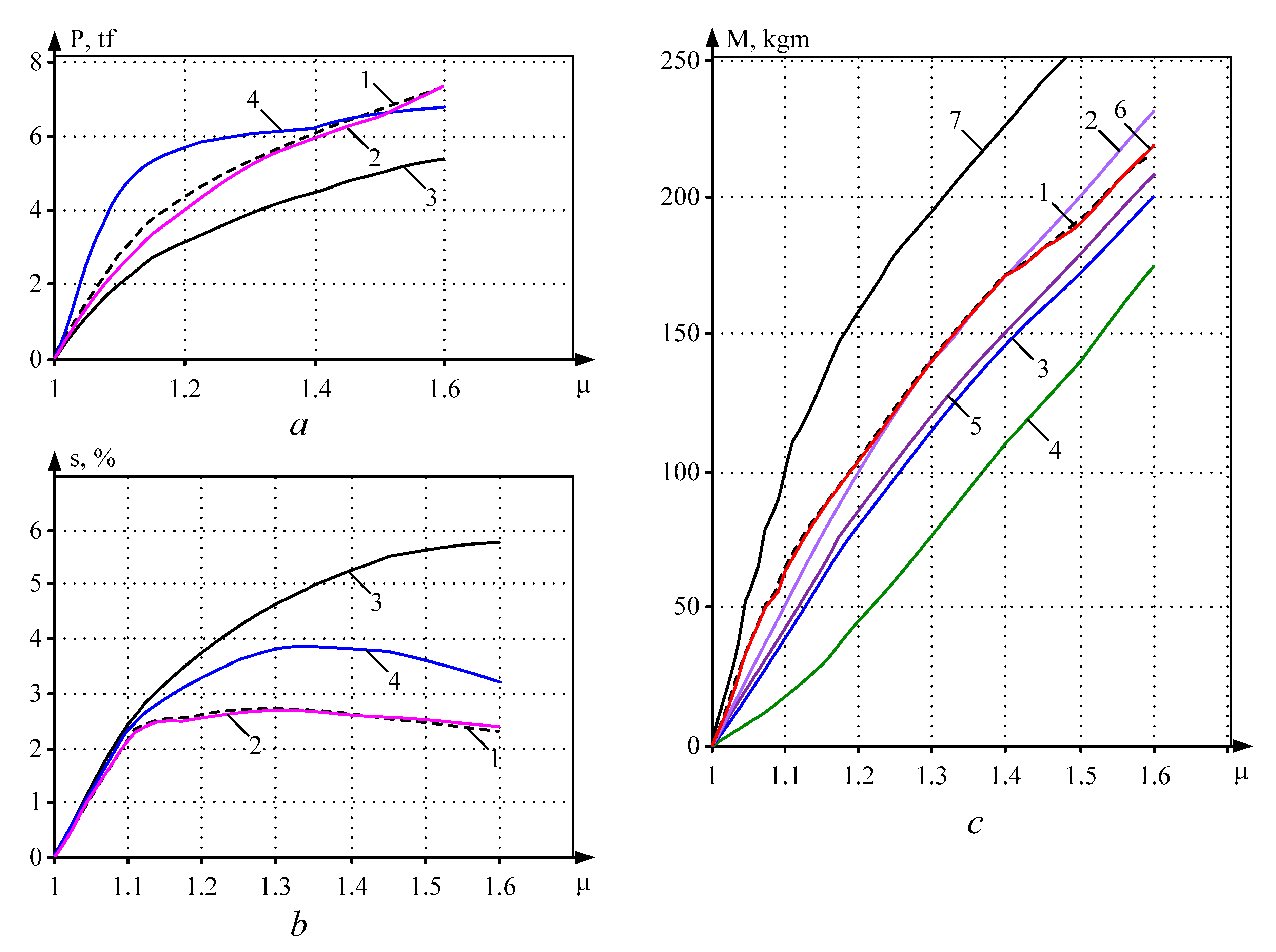
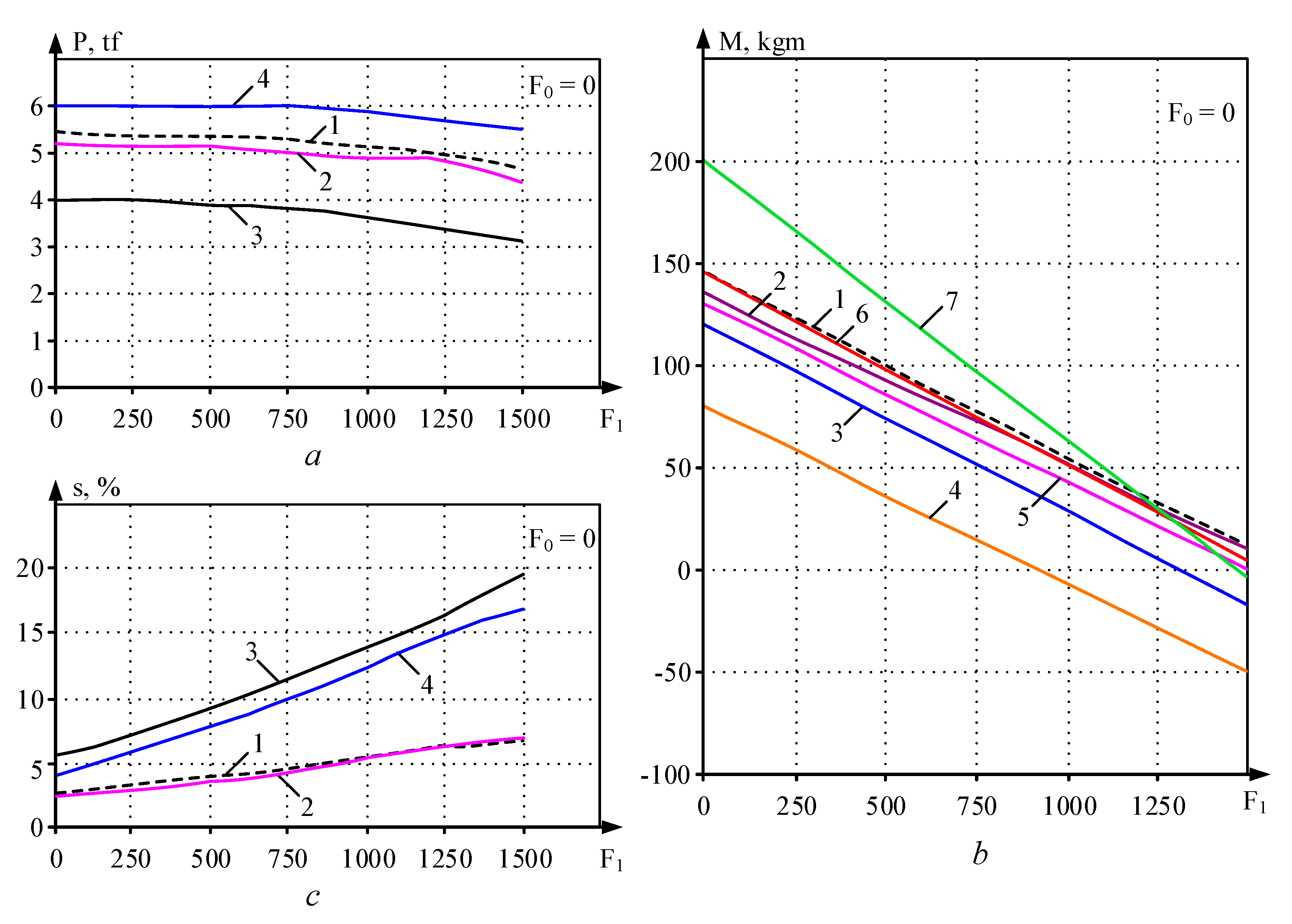
  • The considered analytical expressions and the developed digital model reliably reflect the patterns of the metal deformation process in a multi-roll groove. By the nature of the change, they correspond to the results of experimental studies. However, the degree of impact of the process parameters on the rolling pressure, the mill torque and the metal flow are different.
  • The closest coincidence of the calculated and experimental data is provided by the mathematical model. In the assessed cases, the discrepancy ceiling is 10–15%.
  • From the analytical dependencies considered above, Equation (10) can be recommended for determining the mill torque. It provides acceptable results (the discrepancy at µ = 1.3–1.5 does not exceed 20%) and requires minimal calculations.
  • It is advisable to calculate the metal flow in the deformation zone using the mathematical model only. The use of analytical formulas gives a result that is inflated by 2–5 times.

7. Discussion of the Results

The comparative analysis of the processes shown in Figure 9 and Figure 10 shows that an increase in the wire tension (either front or rear) decreases the rolling force. At the same time, the rear tension has a greater impact on the pressure than the front tension. They also have the opposite effect on the mill torque. With an increase in the front tension from 0 to 1500 kgf (Figure 9b), the torque decreases from ~150 kg∙m (1.5 kN∙m) to zero. This leads to a decrease in the rolling force (Figure 9a), which is quite understandable from the viewpoint of the process “physics”.
An increase in the rear tension leads to an increase in the mill torque (Figure 10b), although the rolling force (Figure 10a) decreases in this case. This is because the rear tension creates a torque that prevents deformation. The increase in the torque of the stand motor provides its compensation.
The results of torque comparison in Figure 6, Figure 7 and Figure 8 confirm the relevance of the development of a tension control system in the inter-stand spaces of a continuous wire mill with multi-roll grooves. Some results obtained in the development of such a system for cold rolling mills are given in publications [38,39,40].
Similar systems have been developed for a continuous subgroup of the roughing group of stands of a broad-strip hot-rolling mill [41,42]. The results of their studies are presented in [43,44,45,46]. However, for mills with multi-roll groove, the solution to this challenge is more complicated than the solution for mills with two-high rolling. Here, the distinctive feature lies in the fact that direct measurement of tension on mills like the one considered is practically impossible—at the same time, its calculation by the parameters of the electric drive is complicated due to the constant change of groove and roll profiles [47,48,49].
That said, the development of such a system is underway, and the research results will be published.
The results of experimental research were applied to check the correctness of theoretical conclusions, calculate and design process, electrical equipment and control systems. This material is abundant and cannot be covered in the scope of one article. It may be considered in the further publications made by the authors.

8. Conclusions

  • The authors carried out a complex of theoretical and experimental studies of power parameters for rolling mills with four-roll pass stands. The obtained results can be used as the initial data for development of new assortments for rolled products or in the design of new mills. The paper analyses the accuracy of determining the power parameters by the known analytical dependences, giving recommendations for their application in calculations.
  • The developed digital model of the deformation zone provides more accurate calculations in comparison with analytical expressions. The discrepancy between the results from the model and from the experimental data does not exceed 10–15%.
  • When calculating the power of actuating units, the mill torque should be defined using the digital model. For approximate calculations, it is advisable to use Equation (10) as it provides results with acceptable precision while requiring the least amount of calculations.
  • The results of experimental research are recommended for the application to optimize drafting, and define energy and power and kinematic parameters and the temperature mode impact at the rolling of the extended range of billets at the existing multi-roll mills.
  • The developed model and program for calculating power parameters are recommended for use in studies of rolling on “conventional” cold rolling mills.

Author Contributions

Conceptualization, M.N.S.; methodology, V.R.K.; software, I.V.L.; validation, O.I.K.; visualization, V.R.K. All authors have read and agreed to the published version of the manuscript.

Funding

The work was carried out with the financial support of the Ministry of Science and Higher Education of the Russian Federation within the framework of a subsidy for financial support for the fulfillment of a state task (fundamental scientific research), contract No. FENU-2020-0020 (2020071GZ).

Conflicts of Interest

The authors declare no conflict of interest.

References

  1. Barkov, L.A.; Samodurova, M.N.; Latfulina, Y.S. Processes of obtaining semi-finished products and rods from titanium alloys by pressing and rolling in multi-roll groove. Stock Mater. Mech. Eng. 2016, 11, 3541. [Google Scholar]
  2. Barkov, L.A.; Samodurova, M.N.; Latfulina, Y.S. Universal mills with multi-roll passes designed by SUSU and their roller assemblies. Russ. Internet J. Ind. Eng. 2017, 5, 11–17. [Google Scholar]
  3. Barkov, L.A.; Samodurova, M.N. Equipment and technology for pressure treatment of hard-to-deform compacted materials. Bull. South Ural State Univ. Ser. Mech. Eng. 2006, 8, 155–161. [Google Scholar]
  4. Pesin, A.; Chukin, M.; Pustovoytov, D. Finite element analysis of symmetric and asymmetric three-roll rolling process. In Proceedings of the MATEC Web Conference, Chengdu, China, 23–24 July 2015; Volume 26. [Google Scholar] [CrossRef] [Green Version]
  5. Barkov, L.A.; Vydrin, V.N.; Pastukhov, V.V. Rolling of Low-Ductility Metals with Multisided Drafting; Metallurgy: Moscow, Russia, 1988; Volume 304. [Google Scholar]
  6. Polyakov, M.G.; Nikiforov, B.A.; Gun, G.S. Metal Strain in Multi-Roll Passes; Metallurgy: Moscow, Russia, 1979; Volume 240. [Google Scholar]
  7. Pesin, A.M.; Pustovoitov, V.O.; Kharitonov, V.A. Method of Cold Rolling of Metal Profiles. RF Patent No. 2617191, B21B 1/28, 21 May 2017. [Google Scholar]
  8. Pesin, A.; Chukin, M.; Korchunov, A.; Pustovoytov, D. Finite element modelling of shear strain in asymmetric and symmetric rolling in multi-roll grooves. Procedia Eng. 2014, 81, 2469–2474. [Google Scholar] [CrossRef]
  9. Pesin, A.; Chukin, M.; Korchunov, A.; Pustovoytov, D. Finite element modelling of shear strain in rolling with velocity asymmetry in multi-roll grooves. Key Eng. Mater. 2014, 622–623, 912–918. [Google Scholar] [CrossRef]
  10. Brauer, H. Kocks rolling mill for tungsten and molybdenum. Metall. Met. Form. 1971, 38, 273. [Google Scholar]
  11. Vydrin, V.N.; Barkov, L.A.; Komarovskiy, I.I. Cold rolling of titanium profiles in multi-roll grooves [Kholodnaya prokatka titanovykh profiley v mnogovalkovykh kalibrakh], Aviatsionnaya promyshlennost. Aircr. Ind. 1978, 3, 54–55. [Google Scholar]
  12. Vydrin, V.N.; Barkov, L.A.; Pastukhov, V.V. Cold rolling of hexagonal profiles from hard alloys [Kholodnaya prokatka shestigrannykh profiley iz trudnodeformiruemykh splavov], Byulleten “Chernaya metallurgiya”. Bull. Ferr. Metall. 1978, 11, 41–43. [Google Scholar]
  13. Selivanov, I.A.; Petukhova, O.I.; Bodrov, E.E.; Suzdalev, I.V. Automated Electric Drive of Continuous Rolling Mills with Multi-Roll Passes; MGTU: Magnitogorsk, Russia, 2008; Volume 252. [Google Scholar]
  14. Karandaev, A.S.; Yakimov, I.A.; Petukhova, O.I.; Antropova, L.I.; Khramshina, E.A. Power parameters of electric drives of five-stand wire rod mill with four-roll passes. In Proceedings of the EIConRus, Moscow, Russia, 1–3 February 2017. [Google Scholar]
  15. Kharitonov, V.A.; Taranin, I.V. Analysis of the stress-strain state in the deformation zone for wire-rod milling in various groove systems based on modelling by the Finite Element method. News High. Educ. Instit. Ferr. Metall. 2013, 2, 26–30. [Google Scholar]
  16. Tretyakov, A.V.; Zyuzin, V.I. Mechanical Properties of Metal Alloys During Pressure Treatment; Metallurgy: Moscow, Russia, 1973; Volume 224. [Google Scholar]
  17. Vydrin, V.N.; Dukmasov, V.G. New in Precision Metal Rolling; South-Urals Publishing House: Chelyabinsk, Russia, 1970; Volume 107. [Google Scholar]
  18. Vydrin, V.N.; Dukmasov, V.G. Precise Rolling of High-Quality Metal; South-Urals Publishing House: Chelyabinsk, Russia, 1965; p. 120. [Google Scholar]
  19. Kharitonov, V.A.; Taranin, I.V. Study of the stress state and failure of metal in wire production by various methods of metal working process. Process. Solid Layer. Mater. 2013, 113–120. [Google Scholar]
  20. Haritonov, V.A.; Taranin, I.V. Modelling of lengthwise rolling in grooves by the finite- elements method. Blank Prod. Mech. Eng. 2013, 7, 36–38. [Google Scholar]
  21. Joo, H.S.; Hwang, S.K.; Baek, H.M.; Im, Y.; Son, I.; Bae, C.M. The effect of a non-circular drawing sequence on spheroidization of medium carbon steel wires. J. Mater. Process. Technol. 2015, 216, 348–356. [Google Scholar] [CrossRef]
  22. Li, Y.H.; Park, J.J.; Kim, W.J. Finite element analysis of severe deformation in Mg–3Al–1Zn sheets through differential-speed rolling with a high-speed ratio. Mater. Sci. Eng. A 2007, 454–455, 570–574. [Google Scholar]
  23. Barkov, L.A.; Vydrin, V.N.; Soloviev, A.V. Power at rolling simple sections in multi-roll passes, rolling theory and technology. In Collection of Research Papers of Chelyabinsk Polytechnic Institute; ChPI: Chelyabinsk, Russian, 1976. [Google Scholar]
  24. Vydrin, V.N.; Barkov, L.A.; Soloviev, A.V. Torque and power at rolling in forming multi-roll passes. Bull. High. Sch. Iron Steel Ind. 1969, 3, 70–73. [Google Scholar]
  25. Vydrin, V.N.; Serdyaga, Y.L.; Nagarnov, V.S. Engineering method of rolling power determination. Bull. High. Sch. Iron Steel Ind. 1972, 3, 115–118. [Google Scholar]
  26. Serdyaga, Y.L.; Vydrin, V.N. Torque and power at rolling in multi-roll passes. In Rolling Theory and Technology. Collection of Research Papers of Chelyabinsk Polytechnic Institute; ChPI: Chelyabinsk, Russian, 1971; Volume 76, pp. 80–85. [Google Scholar]
  27. Eggertsen, P.; Mattiasson, K. On the modelling of the bending–unbending behaviour for accurate springback predictions. Int. J. Mech. Sci. 2009, 51, 547–563. [Google Scholar] [CrossRef]
  28. Eggertsen, P.; Mattiasson, K. On the identification of kinematic hardening material parameters for accurate springback predictions. Int. J. Mater. Form. 2011, 4, 103–120. [Google Scholar] [CrossRef]
  29. Tselikov, A.I.; Grishkov, A.I. Rolling Theory; Metallurgy: Moscow, Russia, 1970; 358p. [Google Scholar]
  30. Radionov, A.A.; Karandaev, A.S.; Evdokimov, A.S.; Andryushin, I.Y.; Gostev, A.N.; Shubin, A.G. Mathematical modeling of electromechanical systems interconnected continuous-subgroup rolling stands. Part 1: Development of a mathematical model. Bull. South Ural State Univ. Ser. Power Eng. 2015, 15, 59–73. [Google Scholar]
  31. Selivanov, I.A.; Salganik, V.M.; Gun, I.G.; Petukhova, O.I.; Mamleeva, Y.I. Control Systems of Continuous Rolling Mills. Bull. High. Inst. Electromech. 2011, 4, 36–40. [Google Scholar]
  32. Shreyner, R.T. Mathematical Modeling ac Electric Drives with Semiconductor Frequency Converters; Ural Branch of the Russian Academy of Sciences: Ekaterinburg, Russia, 2000; p. 654. [Google Scholar]
  33. Certificate on Official Registration of Software Application No. 2009616950. Simulation of Static and Dynamic Modes of Operation of Four-Roll Pass Wire Rolling Mill; Applicant and patent holder GOU VPO Nosov Magnitogorsk State Technical University; No. 2009615980; Petukhova, O.I., Radionov, A.A., Malakhov, O.S., Linkov, S.A., Eds.; Magnitogorsk State Technical University: Magnitogorsk, Russia, 2009. [Google Scholar]
  34. Grudnev, A.P. External Friction at Rolling; Metallurgy: Moscow, Russia, 1971; Volume 215. [Google Scholar]
  35. Benyakovsky, M.A.; Brovman, M.Y. Tensometry Application in Rolling; Metallurgy: Moscow, Russia, 1965; Volume 144. [Google Scholar]
  36. Zagirov, N.N.; Konstantinov, I.L.; Ivanov, E.V. Fundamentals of Calculations of the Processes of Obtaining Long Metal Products by Methods of Pressure-Based Metal Treatment; Siberian Federal University: Krasnoyarsk, Russia, 2011; Volume 312. [Google Scholar]
  37. Nekit, V.A.; Platov, S.I.; Kurbakov, I.A.; Golev, A.D. Experimental study of advancing and lagging in rolling. Bull. Nosov Magnitogorsk State Tech. Univ. 2015, 1, 52–54. [Google Scholar]
  38. Selivanov, I.A.; Petukhova, O.I.; Radionov, A.A.; Suzdalev, I.V. Synthesis of systems of subordinate monitoring of processes at continuous mills. Izv. vuzov. Electromech. 2009, 1, 21–24. [Google Scholar]
  39. Selivanov, I.A.; Petukhova, O.I.; Radionov, A.A.; Suzdalev, I.V. Mathematical modelling of control system for continuous mill when driven stand is powered from power source. Izv. Vuzov. Electromech. 2009, 1, 25–27. [Google Scholar]
  40. Selivanov, I.A.; Petukhova, O.I.; Bodrov, E.Y.; Suzdalev, I.V. Synthesis of control systems for continuous mills with multi-roll calibers. Bull. South Ural State Univ. 2009, 15, 60–63. [Google Scholar]
  41. Andryushin, I.Y.; Galkin, V.V.; Gostev, A.N.; Kazakov, I.V.; Evdokimov, S.A.; Karandaev, A.S.; Khramshin, V.R.; Khramshin, R.R. Method for Automatic Coil Tension Control in the Roughing Group of Continuous Mill Stands. RF Patent No. 2494828, 10 October 2013. [Google Scholar]
  42. Khramshin, V.R.; Karandaev, A.S.; Khramshin, R.R.; Andryushin, I.Y.; Gostev, A.N. Device for Automatic Metal Tension Control in Two Inter-Stand Spaces of Roughing Group of Hot Rolling Mill. RF Patent No. 147042, MPK B21B 37/52, 27 October 2014. [Google Scholar]
  43. Radionov, A.A.; Karandaev, A.S.; Khramshin, V.R.; Andryushin, I.Y.; Gostev, A.N. Speed and load modes of rolling hollow billet at the wide-strip rolling mill. In Proceedings of the MEACS, Tomsk, Russia, 16–18 October 2014. [Google Scholar]
  44. Khramshin, V.R.; Karandaev, A.S.; Evdokimov, S.A.; Andryushin, I.Y.; Shubin, A.G.; Gostev, A.N. Reduction of the dynamic loads in the universal stands of a rolling mill. Metallurgist 2015, 59, 315–323. [Google Scholar] [CrossRef]
  45. Khramshin, V.R.; Evdokimov, S.A.; Karandaev, A.S.; Andryushin, I.Y.; Shubin, A.G. Algorithm of No-Pull Control in the Continuous Mill Train. In Proceedings of the SIBCON, Omsk, Russia, 21–23 May 2015. [Google Scholar]
  46. Andryushin, I.Y.; Shubin, A.G.; Gostev, A.N.; Radionov, A.A.; Karandaev, A.S.; Gasiyarov, V.R.; Khramshin, V.R. Automatic tension control in the continuous roughing train of a wide-strip hot-rolling mill. Metallurgist 2017, 61, 366–374. [Google Scholar] [CrossRef]
  47. Radionov, A.A.; Maklakov, A.S.; Gasiyarov, V.R.; Maklakova, E.A. Research of electric drive at load impact on hot plate mill 5000. In Proceedings of the MEACS, Tomsk, Russia, 1–4 December 2015. [Google Scholar]
  48. Gasiyarov, V.R.; Karandaev, A.S.; Radionov, A.A.; Khramshin, V.R.; Maklakov, A.S. Correcting electric motor drive speed of plate mill stand in profiled sheet rolling. In Proceedings of the PEDES, Chennai, India, 18–21 December 2018. [Google Scholar]
  49. Gasiyarov, V.R.; Radionov, A.A.; Karandaev, A.S.; Loginov, B.M.; Khramshin, V.R.; Maklakov, A.S. Coordinating the modes of the axial roll shifting and roll bending systems of a roll mill stand. In Proceedings of the IECON, Lisbon, Portugal, 14–17 October 2019; pp. 330–335. [Google Scholar]
Figure 1. Layout for rolling a square-shaped stock material: (a) in four-roll pass; (b) in a stand with two three-roll passes.
Machines 08 00073 g001
Figure 2. Production equipment layout diagram: 1, 2—Decoilers (reel or coil); 3—Stretcher/Feeder; 4—Welding Unit; 5—Accumulator; 6—Inductor; 7—Mill Stands; 8—Actuating Units; 9—Cooling Sections; 10—Winder.
Machines 08 00073 g002
Figure 3. Diagram of forces acting on the elementary volume in the backward slip zone.
Machines 08 00073 g003
Figure 4. Explanations for the derivation of equations for l x and t g α x .
Machines 08 00073 g004
Figure 5. Explanations for the derivation of equations for l x and t g α x .
Machines 08 00073 g005
Figure 6. Structural diagram of a mathematical model of a continuous five-stand mill with four-roll passes.
Machines 08 00073 g006
Figure 7. Experimental research at four-roll pass rolling: dependence of rolling pressure on the rolls as a function of the friction coefficient (a), rolling rate (b), drawing down (c), temperature (d); curve 1—steel rolling 70; curve 2—steel R6M5 rolling; curve 3—steel KhI8N9T rolling
Machines 08 00073 g007
Figure 8. Calculated and experimental dependencies of pressure (a), flow (b) and torque (c) from the draw-down operation when rolling a wire rod with 11 mm diameter.
Machines 08 00073 g008
Figure 9. Calculated and experimental dependences of pressure (a), torque (b) and flow (c) from the front tension.
Machines 08 00073 g009
Figure 10. Dependencies similar to Figure 9, (a), torque (b) and flow (c) from rear tension.
Machines 08 00073 g010
Table 1. Four-Roll Pass systems.
DescriptionDiagramDraw-Down Ratio
Circle–square Machines 08 00073 i001µ = 1.57
Circle–octagon Machines 08 00073 i002µ = 1.11
Octagon–square Machines 08 00073 i003µ = 1.66
Octagon–octagon Machines 08 00073 i004µ = 1.17
Octagon–circle Machines 08 00073 i005µ = 1.05
Table 2. Main steel grades and alloys used in the research.
MaterialOriginal Rod Wire Diameter, mmInitial Billet Heat Treatment
CharacteristicsGrade
Pearlite high carbon steelShKh155.5–8Oxidizing annealing in chamber furnaces
Ledeburite chisel rapid steelR6M5
RI8
5.5–8Oxidizing annealing in chamber furnaces
Ferritic and martensite stainless corrosion-resistant steelIKhI35.5–8Annealing in the furnaces with a blanketing atmosphere
Austenitic stainless corrosion-resistant steelKhI8N9T5.5–8Annealing in the furnaces with a blanketing atmosphere
Ferritic scale-proof steel0Kh23Yu5A 0Kh27Yu5A8Annealing in the furnaces with a blanketing atmosphere
Austenitic heat-resistant nickel-based alloysKhN568MTYuR KhN678MTYu6.5Hardening 1200 °C outside
Publisher’s Note: MDPI stays neutral with regard to jurisdictional claims in published maps and institutional affiliations.

