Article

Unified Human Intention Recognition and Heuristic-Based Trajectory Generation for Haptic Teleoperation of Non-Holonomic Vehicles

1
School of Vehicle and Energy, Yanshan University, Qinhuangdao 066004, China
2
Hebei Key Laboratory of Special Delivery Equipment, Yanshan University, Qinhuangdao 066004, China
*
Author to whom correspondence should be addressed.
Machines 2023, 11(5), 528; https://doi.org/10.3390/machines11050528
Submission received: 7 April 2023 / Revised: 1 May 2023 / Accepted: 2 May 2023 / Published: 4 May 2023

Abstract

:
In this paper, a novel bilateral shared control approach is proposed to address the issue of strong dependence on the human, and the resulting burden of manipulation, in classical haptic teleoperation systems for vehicle navigation. A Hidden Markov Model (HMM) is utilized to handle the Human Intention Recognition (HIR), according to the force input by the human—including the HMM solution, i.e., Baum–Welch algorithm, and HMM decoding, i.e., Viterbi algorithm—and the communication delay in teleoperation systems is added to generate a temporary goal. Afterwards, a heuristic and sampling method for online generation of splicing trajectory based on the goal is proposed innovatively, ensuring the vehicle can move feasibly after the change in human intention is detected. Once the trajectory is available, the vehicle velocity is then converted to joystick position information as the haptic cue of the human, which enhances the telepresence. The shared teleoperation control framework is verified in the simulation environment, where its excellent performance in the complex environment is evaluated, and its feasibility is confirmed. The experimental results show that the proposed method can achieve simple and efficient navigation in a complex environment, and can also give a certain situational awareness to the human.

1. Introduction

Bilateral remote control has been a popular issue since master–slave mechanical systems were developed for handling radioactive material [1,2]. In recent years, with the rise in autonomous driving and autonomous mobile robot industry, vehicle remote control and navigation tasks have attracted great attention [3]. Earlier studies have shown that effective force feedback can promote the successful completion of navigation tasks in the remote control of land wheeled robots [4]. Since then, remote control of moving vehicles based on force/haptic feedback has gradually become a new research hotspot [5,6,7,8].
Obstacle avoidance is a very important and challenging task in teleoperation of vehicles in complex environments, which requires strong control skills and a high cognitive level of the human operator. In the above cases, obstacle avoidance problems can be divided into three kinds of rough solutions. The first is based on force feedback, which models the environmental information, namely, the obstacle information, as repulsive force and the target information as attractive force, so as to achieve avoidance [3,9,10,11,12]. This situation is similar to the modeling idea of artificial potential field function in trajectory planning, which requires an ingenious repulsive function design method to avoid obstacle avoidance failure due to the potential instability between the operator and the interaction force. The second is the obstacle avoidance method based on virtual fixture/haptic restriction [13,14,15,16], which is based on environmental information and expected trajectory, and applies corresponding restrictions in the master–slave maneuvering space to achieve obstacle avoidance. This method requires the maneuvering skill of the operator and additional maneuvering effort to achieve collision-free movement of the slave side.
The above two methods are local obstacle avoidance strategies. In addition, the shared teleoperation scheme with active obstacle avoidance strategy is a third solution, which fully combines human high-level decision making and machine autonomy, which greatly reduces the operating burden of the human [3,17,18,19,20,21]. Here, trajectory planning is added for vehicle autonomous navigation to achieve obstacle avoidance. Current studies on trajectory generation roughly include graph search, random sampling, potential field, curve interpolation, and optimal control methods [22,23]. In [19], trajectory generation based on random sampling is adopted to assist the human to operate the vehicle to achieve obstacle-free movement, but the hidden state number in HMM only divides the working space of the aerial robot into 12 equal parts, without giving a reasonable explanation and calculation as to why it is 12 parts. Moreover, in the process of path planning, RRT planning algorithm is adopted, which is unable to deal with complex constraints, and its generated motion state is blind, leading to instability of the final solution—meaning the solution is usually not optimal. The method based on optimization adds constraints and task requirements according to a dynamic system model to form an optimal control problem. This describes the planning task of a mobile robot in the form of an optimal control problem, which is intuitive, accurate and objective; this has been used in unstructured environments such as automatic parking [24], mining [25], and so on. The trajectory generation in this paper elaborates on this method.
In addition, in the teleoperation framework, the communication delay between master and slave systems cannot be ignored. Many researchers have added communication delay processing into teleoperation control [26,27,28,29]. It is mentioned in an earlier study that several “move and wait” cycles were used to process communication delay compensation. It is also shown that predictor display can greatly improve the handling performance of master–slave systems, and the target position generation is an important part of bilateral shared teleoperation control schemes with trajectory generation [19]. Based on the above considerations, the manipulative force of the human is sampled in this paper, mapping it to the vehicle speed, which is combined with the communication delay in the teleoperation system, together constituting the target position of the vehicle at the next moment.
Adding the understanding and recognition of the human’s intention into the remote control can help to correct the human’s possible control mistakes and, at the same time, help the human operator to better move the vehicle [19,30,31]. Therefore, this paper adds the HIR on the basis of the above, takes the human’s control force as the input, and identifies it as the slave position that the human operator wants the vehicle to reach, so as to serve as the input of trajectory generation. There are three types of methods for HIR. Firstly, there are linear models, such as HIR based on a state model and a Kalman Filter, which have been applied to rehabilitation robots [32] and also commercialized [33]. Secondly, in order to identify nonlinear factors in HIR, some nonlinear models, such as neural networks (NNs) and support vector machines (SVMs), have been applied to trajectory tracking of robot limbs [34]. However, such linear or nonlinear deterministic models cannot accurately describe the inherent randomness in human behavior. Moreover, human–machine collaboration usually occurs in the case of noise and incomplete information, in which case the probability-based approach (i.e., the third method) is more robust [31]. The relevant literature [31] is about virtual reality robot-assisted welding tasks, which focus on the recognition of the commanding human’s intentions that should be executed by the welding robot. The motion speed information of the human operator is transformed into the speed information of the welding torch by HMM training, to realize human–machine collaborative welding operation. Therefore, HIR methods have emerged, including HMM (which is a kind of model related to probability and time sequences) [35,36,37], hierarchical HMM [38], incremental HMM [39], and Bayesian estimation [40].
This paper proposes a bilateral shared teleoperation control scheme for ground vehicles with non-holonomic constraints, and adds HIR to the online heuristic trajectory generation. The following are the main contributions of this paper:
  • A bilateral shared teleoperation control scheme based on admittance is proposed to realize the HIR based on the HMM. Through solving the model and determining the model parameters, the identification results are finally used for trajectory generation;
  • Based on the HIR, an online heuristic trajectory generation strategy is proposed to realize feasible and smooth online trajectory docking of vehicles in complex environments, and finally send the trajectory information to the vehicle motion controller;
  • The bilateral shared teleoperation control scheme described in this paper realizes the balance between the autonomy of the system and the control right of the human. Under this framework, the human only needs to give high-level instructions, rather than low-level vehicle trajectory plan and control. In this process, the movement information of the vehicle is still transmitted to the human through the control handle in the form of haptic cues.
The following organizational structure of this paper is as follows: Section 2 introduces the structure design of teleoperation control terminal, that is, the joystick, and the proposed bilateral shared teleoperation control scheme. Section 3 introduces the definition and solution of manipulation intention. Section 4 introduces an online heuristic trajectory generation strategy based on HIR. Finally, the simulation verification of the proposed method is presented in Section 5.

2. System Configuration

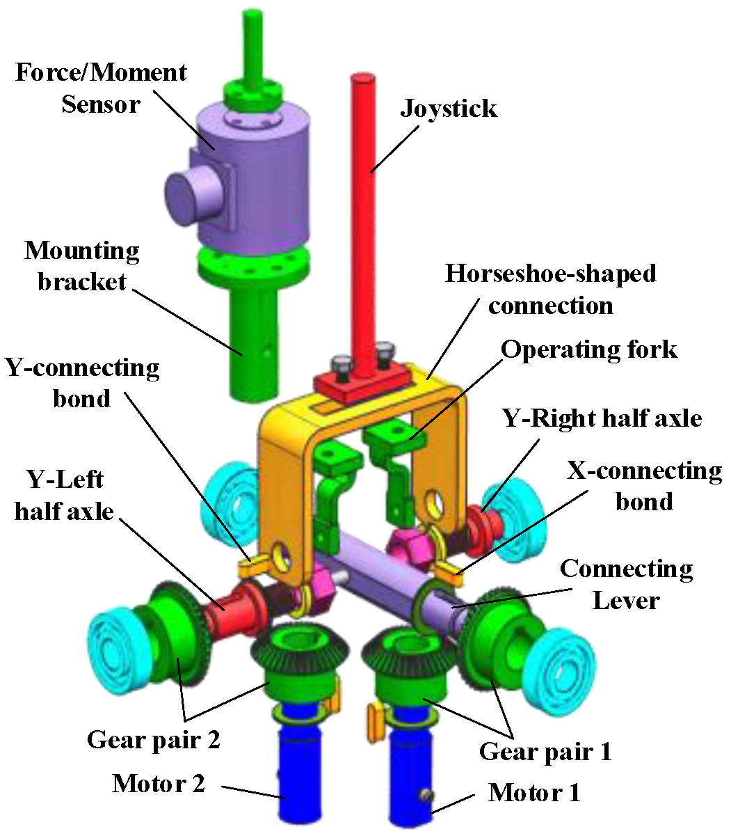
2.1. 2-DOFs Joystick Design

Haptic control terminal, i.e., haptic joystick, is the medium of information exchange between the operator and the remote vehicle. Figure 1 shows the new 2-DOFs control joystick designed in this paper. Two parallel servo motors are arranged side by side as the driving unit, and is then driven by spatial vertical staggered bevel gears, so as to realize the movement and force transfer from the motor to the end of the joystick. Compared with the hydraulically driven control handle [41], the control joystick described in this paper is a mainly lightweight and compact design. The moment of inertia of its transmission components is relatively small, so the system is of fast response. Moreover, the degrees of freedom of the control joystick in two directions are independent from each other, so consideration of decoupling is not needed in the actual motion control. HIR requires the acquisition of the slave vehicle’s reference speed in real time through the interaction force between the human and the joystick, namely, the human hand force. Therefore, a force sensor is installed at the end of the joystick to obtain the control force exerted by the operator on the joystick.
The haptic generation of the joystick is divided into impedance control and admittance control under the teleoperation framework [5]. The impedance haptic interface [42,43,44] is characterized by mapping information in the remote environment to the joystick in the form of force, such as obstacle avoidance force, target attractive force, etc. The admittance haptic interface [45,46,47] is relatively famous for reflecting the dynamic characteristics and the inertia of the system, so it is more inclined to provide the operator with the environment boundary information and vehicle motion condition. Under the bilateral teleoperation framework described in this paper, the obstacle avoidance problem is solved by the trajectory generation module. At this time, the interaction between the vehicle and the environment is not very frequent. In this case, the feedback generated by the obstacle avoidance force and target attractive force is no longer the haptic information of concern to the human, but the vehicle motion information becomes relatively more important. Based on the above considerations, the admittance haptic configuration is more suitable for the framework proposed in this paper. As shown in Formula (1), the sensor installed at the end of the joystick is used to measure the control force F as the speed reference v r of the vehicle under the admittance haptic interface, and then the real-time speed v of the vehicle relative to the position P r of the joystick to generate haptic cues:
{ v r = k F F P r = k P v
Here, k F and k P are the corresponding factors.

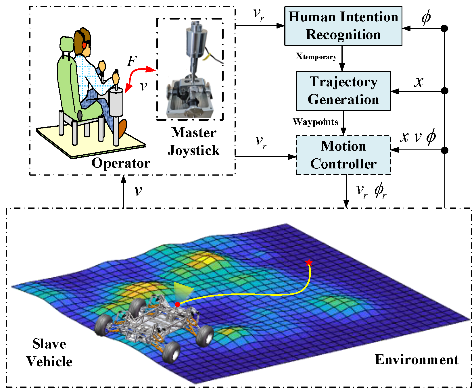
2.2. Bilateral Teleoperation Scheme with Haptic Cues

The bilateral teleoperation method based on HIR and trajectory generation is elaborated in this section. The organizational structure of the system is shown in Figure 2. Inspired by the teleoperation for multirotor aerial robots mentioned in the literature [19], the system described in this paper includes a 2-DOFs joystick (explained in Section 2.1), HIR module, trajectory generation module, and motion controller module. In order to highlight the key content of this article, the motion controller design within the dotted-line frame is not included in this paper.
The system takes the force measured at the joystick as input and transmits it to the HIR module and motion controller. The HIR module generates the human’s intention according to the force measured, and the HMM is used to obtain the discrete human’s intention estimation, after which the corresponding speed information is obtained. Finally, communication delay information is added to generate the desired target position of the human. According to the target position generated above, the optimal control strategy and the idea of sampling points with splicing are innovatively adopted to generate a feasible trajectory without obstacles. Once the trajectory is available, the speed information input by the human can be sent to the vehicle controller to manipulate the vehicle moving along the generated trajectory. Meanwhile, the real-time speed information of the vehicle is also sent to the joystick, generating haptic cues that give the human more intuitive vehicle motion information.

3. Human Intention Recognition

3.1. Human Intention Definition

Human intention can have various meanings in certain operating environments. In a haptic teleoperation task, a series of commands given by the human to the slave vehicle are used to guide the vehicle to a series of temporary target positions, which guide the vehicle to the final position step by step. Thus, human intention in this article is defined as the position the human wants the vehicle to reach.
Considering the haptic bilateral control framework constructed in this paper, the control force input by the human through the joystick is mapped to the vehicle command, namely, the speed command, which is used to control the vehicle. Moreover, if the human wants the vehicle to reach a further location, the speed of the vehicle will increase at the same time, and the human’s control over the joystick will increase accordingly. Therefore, the force of the human can be considered to some extent as an approximate mapping of the desired motion of the vehicle. If the target position is regarded as the actual intention of the human and the force at the joystick terminal is deemed as the observation of the human intention, the above relationship can be described by the HMM. The actual intention of the operator is the hidden state, and the control force is the corresponding observation. However, considering the continuity of the vehicle workspace, there are an infinite number of “target positions” in the actual situation, and it is unnecessary or impractical to use a large number of human intentions in the actual intention estimation. Therefore, according to the actual working space of the vehicle, the human intention is discretized and divided into several angles and sizes in a fan-shaped distribution.

3.2. Hidden Markov Model Principle

HMM is a model relating to probability and time sequence, introducing the process of generating a state sequence randomly that is unobservable by Hidden Markov Chain, and then an observation sequence is available at each state [31,35,37,48].
Suppose Q = q 1 , q 2 , , q N is the set including all hidden states and V = v 1 , v 2 , v M is the corresponding set of observation states, where N is the number of total possible hidden states and M is the corresponding number of possible observations.
The real-time hidden state i can be accessed through the state probability transition matrix: A = a i j N × N , representing the probability of being in state q j at time t + 1 , based on the premise of being in state q i at time t . Meanwhile, in each corresponding hidden state, the observed state O can be described by an emission probability matrix: B = b j k N × M , representing the probability of generating observation state v k , based on the premise of being in state q j at time t . Initial state probability matrix π = π i = P i 1 = q i , i = 1,2 , N represents the probability of being in state q i at time t = 1 . The above three matrices together form the HMM: λ = A , B , π .
For our HIR problem, the complete implementation process is listed in Algorithm 1. The force F = f 1 , f 2 T of the human on the 2-DOFs joystick is taken as the observation sequence, and B is assumed to obey the Gaussian distribution law:
P ( o | q i ) = 1 2 π | Σ i | exp ( 1 2 ( o μ i ) T Σ i 1 ( o μ i ) )
where μ i represents the mean matrix of the measured force and i represents the corresponding covariance matrix. With the remote control of the vehicle by the human, the observation and the corresponding hidden states sequence is generated.
Algorithm 1 Human intention estimation algorithm
\begin{minipage}{12cm}
\begin{algorithm}[H]
\begin{footnotesize}
\setcounter{algorithm}{0}
    \caption{{\footnotesize Human intention estimation algorithm}}
    \label{2}
    \begin{algorithmic}[1]
     \State Discretizing the human intention workspace into 8 parts equally
     \State Initializing the hidden states probability matrix $\pi$
     \State Measuring a set of user force input $f_{h}(t)$ for model initialization
     \State Compute $P(o_{1}|q_{1})$ using the Gaussian distribution law
     \vspace{1ex}
     \State $f(o_{i})=\frac{1}{\sqrt{(2\pi)^2|\sum|}}exp(\frac{1}{2}(o_{i}-\mu)^T\sum^{-1}(o_{i}-\mu))$
     \vspace{1ex}
     \State Update the state-transition matrix $A$
     \State Compute the initial probability $P(q_{1}|o_{1})$
     \vspace{1ex}
     \State $P(q_{1}|o_{1}) $\propto$ P(o_{1}|q_{1})P(q_{1})$
     \vspace{1ex}
     \State Update the emission probability matrix $B$
     \State Using Baum-Welch algorithm to get $\lambda$ including $A$,$B$ and $\pi$, such that
     \Repeat
       \State Measure user force input $f_{h}(t)$ in real time and compute $o_{t}$
       \State Update the observation sequence $O_{t}$
       \State Time update:
       \vspace{1ex}
       \State $P(i_{t+1}=q_{j}|O_{t+1})=P(i_{t+1}=q_{j}|i_{t}=q_{i})P(i_{t}=q_{i}|O_{t})$ and update $A$
       \vspace{1ex}
       \State Obsevation:
       \vspace{1ex}
       \State $P(i_{t+1}=q_{j}|O_{t+1}) $\propto$ P(o_{t+1}|i_{t+1}=q_{j})P(i_{t+1}=q_{j}|O_{t})$ and update $B$
       \vspace{1ex}
       \State Find the intention state $q_{j}$ using Viterbi algorithm, such that
       \vspace{1ex}
       \State $j=\mathop{argmax}\limits_{1\le j\le N}{P(i_{t+1}=q_{j}|i_{t}=q_{i})}P(i_{t}=q_{i})$, $i_{t+1} \in Q $
       \vspace{1ex}
       \State Pass the reference velocity $v_{r}$ and the hidden state $q_{j}$ to the trajectory
      \State generator
     \Until termination
    \end{algorithmic}
    \end{footnotesize}
   \end{algorithm}
\end{minipage}

3.3. HMM Identification

3.3.1. Baum–Welch Algorithm

In the HMM established in this paper, the observation sequence O can be obtained in real time by the force/torque sensor, but its corresponding hidden state is not observable. Baum–Welch algorithm is used to solve the model through the method of maximum likelihood estimation parameters, namely, letting P O | λ be the maximum under the conditions of the model, from which parameters are obtained:
λ o p t i m a l = arg max λ ( O log P ( O | λ ) )
Here, O is a set of observation sequences obtained in real time, denoted as O = O 1 , O 2 , , O T , with corresponding hidden state sequence I = i 1 , i 2 , , i T , so the complete dataset is O , I = O 1 , O 2 , , O T , i 1 , i 2 , , i T , and its corresponding logarithmic likelihood function can be expressed as l o g P O , I | λ . The solution of model parameters can be divided into expected iteration (E step) and maximization (M step):
(1)
E Step:
Define the Q function:
Q ( λ , λ ( h ) ) I O P ( I , O | λ ( h ) ) log P ( I , O | λ )
According to the properties of HMM:
P ( I , O | λ ) = π i 1 b i 1 ( o 1 ) a i 1 i 2 b i 2 ( o 2 ) a i 2 i 3 ... b i T 1 ( o T 1 ) a i T 1 i T b i T ( o T )
Substituting Q function, we can obtain the following:
Q ( λ , λ ( h ) ) = I O P ( I , O | λ ( h ) ) log [ π i 1 t = 1 T b i t ( o t ) t = 1 T a i t i t + 1 ] = I O P ( I , O | λ ( h ) ) log π i 1 Q I + I O ( P ( I , O | λ ( h ) ) ( t = 1 T log b i t ( o t ) ) ) Q E = + I O ( P ( I , O | λ ( h ) ) ( t = 1 T log a i t i t + 1 ) ) Q T
Since the three parameters that need to be maximized appear respectively in Q I , Q E , and Q T , the three parts of the addition term can be maximized;
(2)
M Step:
Maximizing Q function in step E, that is, updating a step size, the model parameter is as follows:
λ ( h + 1 ) = arg max λ Q ( λ , λ ( h ) )
Specifically, partial derivatives are obtained for each part of the Q function in step E, and when partial derivatives are set to 0, we can obtain the following:
{ Q ( λ , λ ( h ) ) π i 1 = 0 Q ( λ , λ ( h ) ) μ i = 0 Q ( λ , λ ( h ) ) i = 0 Q ( λ , λ ( h ) ) a i j = 0 { π i 1 = O γ ( i 1 k ) O k = 1 M γ ( i 1 k ) μ i = O t = 1 T k = 1 M ( γ ( i t k ) o t ) O t = 1 T k = 1 M γ ( i t k ) i = O t = 1 T k = 1 M ( γ ( i t k ) ( o t μ i ) ( o t μ i ) T ) O t = 1 T k = 1 M γ ( i t k ) a i j = O t = 2 T ( ξ ( i t 1 k , i t j ) ) O t = 2 T j = 1 M ( ξ ( i t 1 k , i t j ) )
Here, ξ and γ are calculated using forward and backward probabilities:
{ α t ( i ) = P ( o 0 , o 1 , ... , o t , i t = i ) = j = 1 n α t 1 ( j ) a j i b i ( o t ) β t ( i ) = P ( o t + 1 , o t + 2 , ... , o T | i t = i ) = j = 1 n β t + 1 ( j ) a i j b j ( o t + 1 ) ξ i j ( t ) = ( i t + 1 = j , i t = i | O ) = α t ( i ) a i j b j ( o t + 1 ) β t + 1 ( j ) i = 1 n α t ( i ) β t ( i ) γ i ( t ) = P ( i t = i | O ) = j = 1 n ξ i j ( t )

3.3.2. Training Data Acquisition

The experimental task refers to a specific scene (including obstacles) in which the user specifies a starting point, several middle points, and an end point of the vehicle navigation. The operator shifts the joystick, assisting the vehicle to complete a specific trajectory at the remote side. In this process, the human force is sampled at a frequency of 50 Hz to collect several sets of observation sequences.

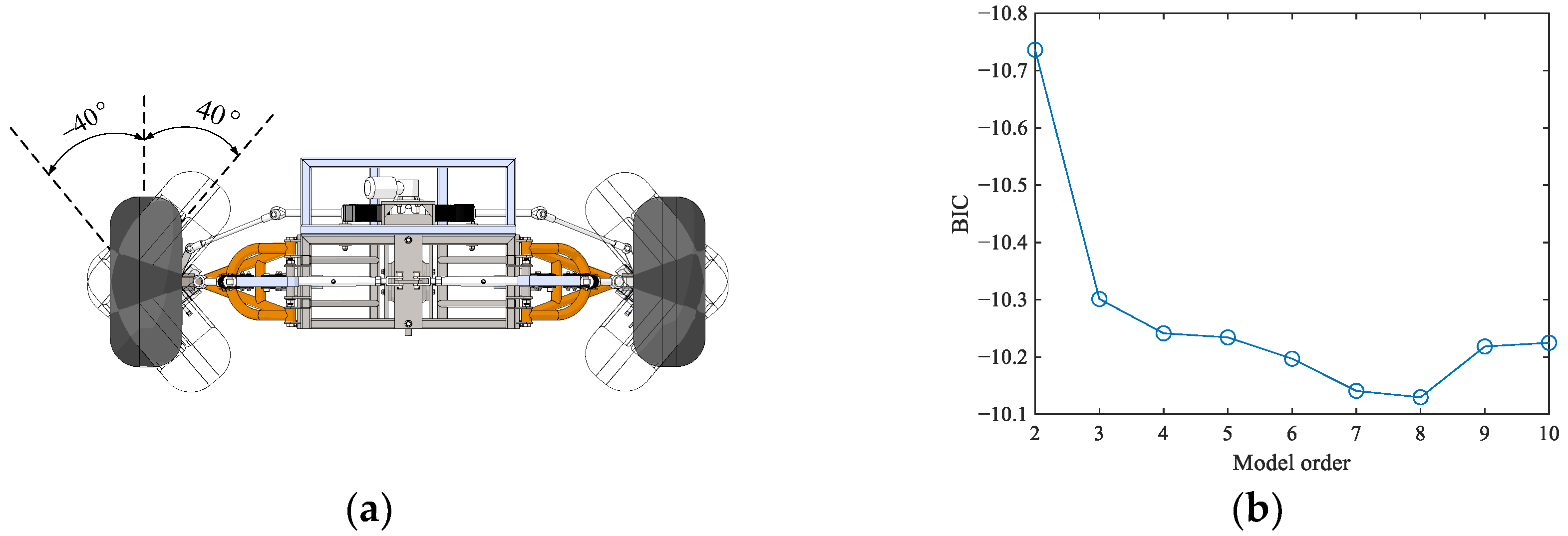
3.3.3. Hidden State Number Identification
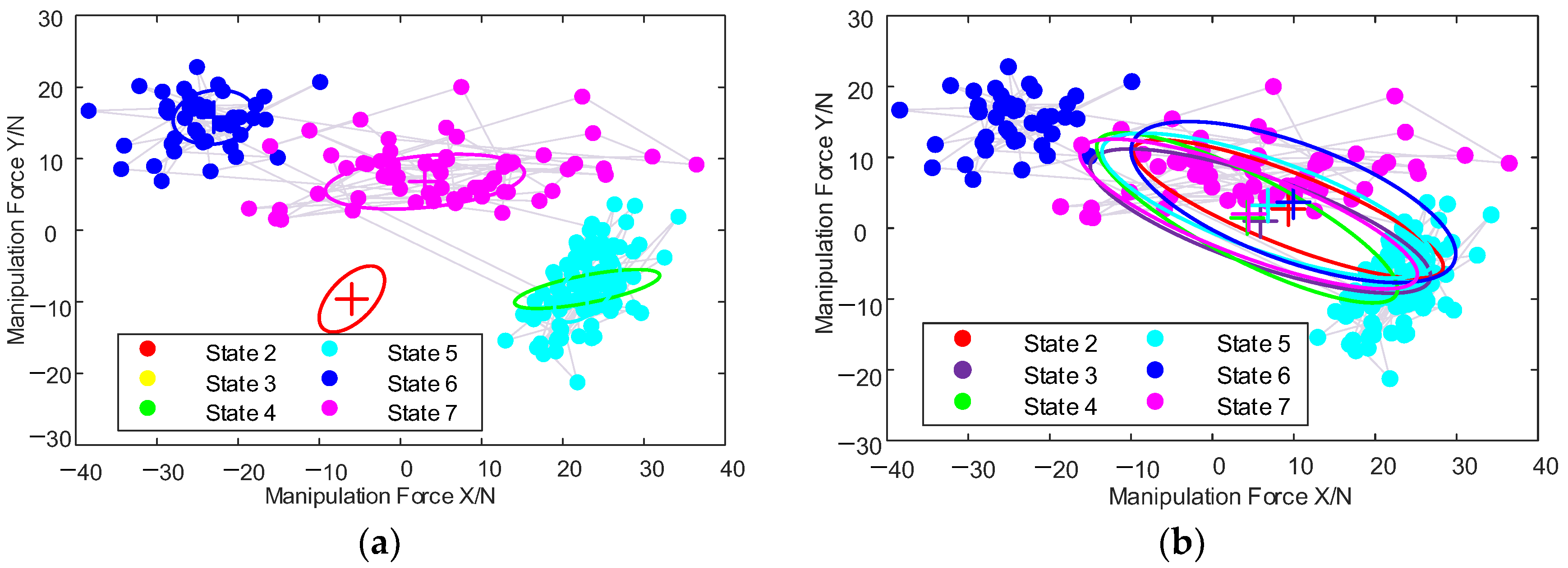
In the HMM constructed in this paper, the intention of the human is modeled as the position that they want the vehicle to reach. The center point of the rear axle of the vehicle body is taken as the zero reference, and the spatial scale of the vehicle steering system is discretized. Theoretically, the spatial scale of the vehicle steering system is a fan-shaped area, as shown in Figure 3a. In this paper, it is assumed that the limiting angle of the vehicle is 40 degrees, so the human intention spans 80 degrees in space. After determining the number of hidden states, the corresponding discretization is carried out equidistantly. The number of discretization intervals also determines the number of hidden states, which cannot be accessible in advance. In this paper, the Bayesian Information Criterion (BIC) is adopted to determine the number of hidden states of the HMM, which provides the criteria for weighing the complexity of the model and the goodness of fit of the data:
B I C = 2 log ( L ) + κ log ( n )
Here, L represents the maximum likelihood probability of the observation sequence, and κ is the number of independent parameters to be learned in the model, including initial matrix parameters κ π , emission matrix parameters κ μ and κ , and the transition matrix parameters κ A ; hence, κ = κ π + κ μ + κ + κ A . n represents the sample size. Assuming that the number of hidden states is N :
{ κ π = N 1 κ μ = ε N κ = ε ( ε + 1 ) N / 2 κ A = N ( N 1 )
In the application scenario described in this paper, o = F = f 1 , f 2 T , meaning the observation data are two-dimensional, i.e., ε = 2 . The model parameters substituted into (11) are as follows:
κ = N 2 + 5 N 1
Using the Baum–Welch algorithm, in order to reduce the impact of the initial value of the model parameters on the final result, the initial value is set arbitrarily, and the model parameters are trained multiple times. As shown in Figure 3b, by comparing the final BIC value, the number of hidden states is set to eight.

3.3.4. HMM Training

After determining the number of hidden states to be eight, the above-mentioned Baum–Welch algorithm is repeated to train the model with random initial setting several times, as shown in Figure 4, until the model converges to a reasonable error range. Here symbol + represents the mean of a two-dimensional Gaussian ellipse.

3.4. Human Intention Recognition

After obtaining all parameters of the HMM, the probability of each observation sequence can be evaluated through Formula (2), and then the most likely probability is taken as the current state, which is, essentially, a decoding problem of the HMM. Calculating the maximum probability δ of each path recursively whose state is i at time t :
{ δ t ( i ) = max i 1 , i 2 , ... i t 1 P ( i t = i , i t 1 , ... i 1 , o t , ... o 1 | λ ) δ t + 1 ( i ) = max i 1 , i 2 , ... i t P ( i t + 1 = i , i t , i t 1 ... i 1 , o t + 1 , o t , ... o 1 | λ ) = max j δ t ( j ) a j i b i ( o t + 1 )
Until the termination time t = T , the maximum probability of each path in state i , at this time the maximum probability corresponding to time T , is the optimal path probability. Then, finding each node along the optimal path starts from the end node i T * , looks for each node from the last to the first, and obtains the optimal path I * = i 1 * , i 2 * , i T * , where the t 1 node of the path with the highest probability among all single paths with state i at time t is shown in formula (14):
ψ t ( i ) = arg max j [ δ t 1 ( j ) a j i ]

4. Online Heuristic Trajectory Generation Based on HIR

In this part, the optimal control idea is used to solve the trajectory based on the target goal identified by the HIR module. Since the driving speed of the vehicle in a complex environment is low and the impact of sideslip is small, the vehicle two-degree-of-freedom model is used in the model construction of the trajectory generation problem:
{ d x ( t ) d t = v ( t ) cos θ ( t ) d y ( t ) d t = v ( t ) sin θ ( t ) d θ ( t ) d t = v ( t ) tan ϕ ( t ) L
where t represents time; P x t , y t represents the coordinates of the midpoint of the rear wheel axis of the vehicle, which is used to represent the real-time location of the vehicle; v t represents the speed; θ t represents the direction angle; ϕ t represents the front wheel angle; and L represents the longitudinal distance between the front and rear wheels. In this equation, the variables that can be differentiated are vehicle position x(t) and y(t), vehicle velocity v(t), vehicle attitude angle θ(t), and vehicle steering angle ϕ(t), all of which are called state variables. In addition, there are two variables that have not been differentiated: a(t) and ω(t), which are called control variables. The reason why these two variables, i.e., a(t) and ω(t), are chosen as control variables is that, from these two variables, other state variables can be uniquely determined using integration. From this perspective, these two variables embody the meaning of controlled vehicle motion. For all the state/control variables described above, there are inherent mechanical characteristics of vehicles, which generally include v(t), ϕ(t), a(t), and ω(t). For example, the speed and the wheel angle cannot be infinite, due to the mechanical structure. They all have permissible ranges of action. Therefore, in the actual solution, the four variables need to be limited to make the solution results more in line with the actual motion of the vehicle.
In the construction of obstacle avoidance constraints, the vehicle is represented by double circles, the centers of which are the two quarters of the longitudinal axis of the vehicle, and the position of the vehicle is represented by the center of the double circles, as shown in Figure 5a. Additionally, the position and radius of the center of the circle can be obtained from the geometric parameters of the vehicle:
[ x f ( t ) y f ( t ) x r ( t ) y r ( t ) ] = [ x ( t ) y ( t ) x ( t ) y ( t ) ] + 1 4 [ cos θ ( t ) 0 0 0 0 sin θ ( t ) 0 0 0 0 cos θ ( t ) 0 0 0 0 sin θ ( t ) ] [ 3 3 1 3 3 1 1 1 3 1 1 3 ] [ L N M ] R = 1 2 ( ( N + L + M 2 ) 2 + ( 2 B ) 2 ) 1 / 2
where P f x f t , y f t and P r x r t , y r t represent the center positions of the two double circles, respectively, R represents the double circle radius, N represents the length of the front overhang, M represents the length of the rear overhang, and 2 B represents the width of the vehicle.
As shown in Figure 5b, according to the initial position defined by the operator, the center position of the double circles and the radii of the double circles are solved, and then the vehicle is simplified into two particles at the center of the double circles. At the same time, the obstacles detected in the environment are bulked together with the size R of the double circle radius. Taking P f as an example, as shown in Figure 5b, assuming that the position of P f at the initial moment is x 0 , y 0 , i.e., the position of the black circle in Figure 5b, the point at this time can be regarded as a rectangle whose center point is x 0 , y 0 , whose length and width are both 0. Then, the rectangle is expanded in four directions clockwise or counterclockwise, taking δ as the step size. The first expansion, counterclockwise, leads to rectangles 1,2,3. Similarly, the second expansion gives us rectangle 4,5,6,7 and the third corresponds to rectangular 8,9,10. If there is a collision with an obstacle during the expansion of the rectangle, the expansion stops. As shown in Figure 5b, rectangles 5, 8, and 9 are discarded due to collisions with obstacles. The L l i m i t parameter is additionally defined here to limit the size of the rectangle, to avoid the waste of computing resources caused by the excessive expansion of the rectangle. For example, the 11th rectangle is discarded. Finally, the rectangle shown by the red dotted line is recorded as the feasible area rectangle, that is, as long as the two centers of the double circles are located in the feasible area rectangle, the obstacle avoidance is considered successful. Therefore, the obstacle avoidance constraint can be defined as a box constraint, as described in Formula (17), which is the simplest linear constraint:
x f ( t ) [ x f min k , x f max k ] y f ( t ) [ y f min k , y f max k ] x r ( t ) [ x f min k , x f max k ] y r ( t ) [ y f min k , y f max k ] t = Τ Ν k k = 1 , 2 , ... Ν
where x f m i n k , x f m a x k and y f m i n k , y f m a x k are the upper and lower limits of the abscissa and the upper and lower limits of the ordinate of the rectangle of the feasible region, respectively, Τ represents the time domain derived from the initial trajectory, Ν represents the number of arbitrarily set feasible region rectangles, and k represents the index value of the feasible region rectangle.
In the teleoperation framework, the human usually observes the real-time environment of the slave side in the form of images or videos at a distance from the vehicle; coupled with the human’s advanced intelligence and existing work experience, the human’s intention represents a more feasible path. Therefore, the results of HIR are added to the trajectory generation module to heuristically complete the entire search process. Specifically, when the HMM module detects a change in the human intention, a certain time interval t is fixed, where the time interval t is set as the communication delay in the teleoperation system, and the force sensor at the joystick detects the force, which is used to generate a new intermediate target goal for the trajectory generation module:
X t e m p o r a r y = X p r e v i o u s + Δ t k f F
If the calculated intermediate target point is located within the obstacle, the current position of the vehicle connects with the position of the intermediate target point and finds a suitable “intermediate target point” on the connection line. Once the target point is determined, the optimal control problem is established, with the shortest time as the goal, and the sub-path connecting the starting point and the intermediate target point is solved in an unstructured environment as time goes by, under the guidance of the human, to heuristically generate an obstacle-free trajectory.
Based on the above settings, this paper proposes an online heuristic trajectory generation strategy, as shown in Figure 6. The pseudocode for trajectory generation is shown in Algorithm 2.
Algorithm 2 Trajectory generation with human intention
\begin{minipage}{12cm}
\begin{algorithm}[H]
\begin{footnotesize}
\setcounter{algorithm}{1}
    \caption{{\footnotesize Trajectory generation with human intention}}
    \label{2}
    \begin{algorithmic}[1]
     \Require
     A target position $X_{temporary}$ representing human intention,
     intention change time $t_{0}$,obstacles $obs$,original trajectory $Traj_{original}$
    \Ensure
      A collaborative trajectory $\varGamma(x,y,\theta,v,\phi,t_{f},a,\omega)$
     \State Identify $t_{0}$ and $X_{temporary}$
     \State Plan an Intention Trajectory by construct an optimal control problem
     \State Initialize a set $\Upsilon = \emptyset $ for alternative trajectory
     \For {each $i$ \in \lbrace1,...,$N_{original}\rbrace$}
       \For {each $j$ \in \lbrace1,...,$N_{intention}\rbrace$}
       \State Plan an alternative trajectory $Traj_{alternative}(t)$ from the pose
       \State $Traj_{original}(t_{i}^{sample})$ to the pose $Traj_{intention}(t_{j}^{sample})$
       \State by solving an optimal problem
         \If {the vehicle $footprints$ ($Traj_{alternative}(t)\notin $obs$ $)}
         \State Put $Traj_{alternative}(t)$ into $\Upsilon$
         \EndIf
       \EndFor
     \EndFor
     \State Initialize $Traj_{connecting} = +\infty$
     \For {each $Traj_{alternative}(t) \in \Upsilon$}
     \State Construct an integrated trajectory $Traj_{integrated}$ and evaluate its cost
     \State $J_{current}$
       \If {$J_{current-best}>J_{current}$}
         \State Set $\varGamma$ \leftarrow $Traj_{integrated}$
         \State Set $J_{current-best}$ \leftarrow $J_{current}$
       \EndIf
     \EndFor
    \end{algorithmic}
    \end{footnotesize}
   \end{algorithm}
\end{minipage}
Initially, at time t = 0 , a rough initial trajectory is generated according to the starting point and any end points set by the human, as shown by the blue line in Figure 6.
Assuming that a change in the HIR module is detected at time t = t 0 , the position of the target point representing the human’s intention is calculated, as shown by the sky blue five-pointed star in Figure 6, and the optimal control problem is constructed based on the position of the target point to solve the trajectory. The trajectory solution time interval is set to t t h i n k , and then, during the time period from t 0 to t 0 + t t h i n k , the vehicle still travels according to the rough track originally planned.
Here, inspired by the human intention, the trajectory generation task of the intended trajectory can be modeled as follows:
min ( t H I G t 0 ) s . t . k i n e m a t i c a l c o n s t r a int ( f o r m u l a   15 ) T w o p o int s c o n s t r a int ( X t s t a r t = X t 0 , X t e n d = X t H I G ) var i a b l e c o n s t r a int ( | v | v max , | ϕ | ϕ max , | θ | θ max , | ω | ω max , | a | a max ) O b s t a c l e a v o i d a n c e c o n s t r a int ( f o r m u l a 17 )
At the time t 0 + t t h i n k , after obtaining the solution result of the intended trajectory, as shown in the purple curve in Figure 6, the vehicle is still on the original rough trajectory. Next, it is necessary to find suitable paths on the original trajectory and the intended trajectory. The connecting point realizes the smooth docking of the vehicle on the two trajectories. Inspired by the online obstacle avoidance and sampling point selection in reference [49], after obtaining the intended trajectory at the time t 0 + t t h i n k , this paper reverts backwards on the original trajectory and the intended trajectory, selects three sampling points, and then arranges them together, finally combining nine candidate connection trajectories to form the following optimal control problems:
min ( t i s a m p l e t j s a m p l e ) s . t . k i n e m a t i c a l c o n s t r a int ( f o r m u l a 15 ) T w o p o int s c o n s t r a int ( X t s t a r t = X t 0 , X t e n d = X t H I G ) var i a b l e c o n s t r a int ( | v | v max , | ϕ | ϕ max , | θ | θ max , | ω | ω max , | a | a max )
In order to ensure that the vehicle can change to the intended trajectory as quickly as possible after the change of the human’s intention is detected, the obstacle avoidance constraint is not considered when solving the connecting trajectory. Rather, after all alternative trajectories are obtained, all obstacle-free trajectories are selected, and then the trajectory with the shortest time to the final connecting trajectory is selected, as shown in the red curve in Figure 6. In summary, the final trajectory is an integrated trajectory composed of the original trajectory, the connecting trajectory, and the intended trajectory, as shown by the green dotted line in Figure 6. By analogy, under the corporate guidance of the human’s decision-making and the vehicle’s autonomous trajectory generation, the vehicle will complete the search task in an environment full of obstacles.

5. Simulation Experiments

5.1. Experimental Configuration

The numerical simulation experiment in this paper is verified using the MATLAB platform. The computer processor is Intel (R) Core (TM) i7-7700 CPU @ 3.60 GHz, 16.0 Gb RAM. The geometric parameters and motion parameter settings of the vehicle are shown in Table 1. Since this paper simplifies the vehicle into a double-circle model, according to the front and rear overhang lengths and longitudinal length of the vehicle, the radius and center position of the double circle can be obtained by Formula (16).

5.2. Experimental Design

In the experimental part, three scenarios are designed, and the size of the three scenarios is set at 20 m × 20 m. Navigation tasks in the three scenarios are shown in Table 2, which are used to verify the online heuristic trajectory generation algorithm based on human intention, as proposed in this paper, and apply it to the bilateral teleoperation system. The generated feedback information can assist the operator to complete navigation tasks in complex scenarios. Concrete obstacles information and experiment configuration can be found at “https://github.com/zhangpanhong666/A-heuristic-search-strategy-based-on-manipulative-intention.git (accessed on 9 March 2023)”.
In each scenario, five irregular polygons are all randomly designed as obstacles. In Scenario 1, the vehicle did not receive any intention change from the human during the navigation, which was tested in order to verify the basic obstacle avoidance function of the proposed trajectory generation algorithm, with the operator playing a supervisory role in this process. In Scenario 2, the vehicle is moving along the already planned trajectory, when it encounters an obstacle suddenly during the navigation and then obstacle avoidance is achieved under the guidance of the human operator. The purpose of Scenario 2 is to verify the robustness of the proposed algorithm in the face of sudden obstacles, ensuring the continuity of navigation, and to prove the perfect adaptability of the trajectory generation algorithm between the human intention and autonomous path planner. In Scenario 3, the starting point and ending point remain unchanged, but two middle goals are added while the vehicle is moving. The scenario is designed to verify the continuity of trajectory generation under the guidance of the human operator and the balance between the human intention and autonomous planner.

5.3. Experimental Results and Analysis

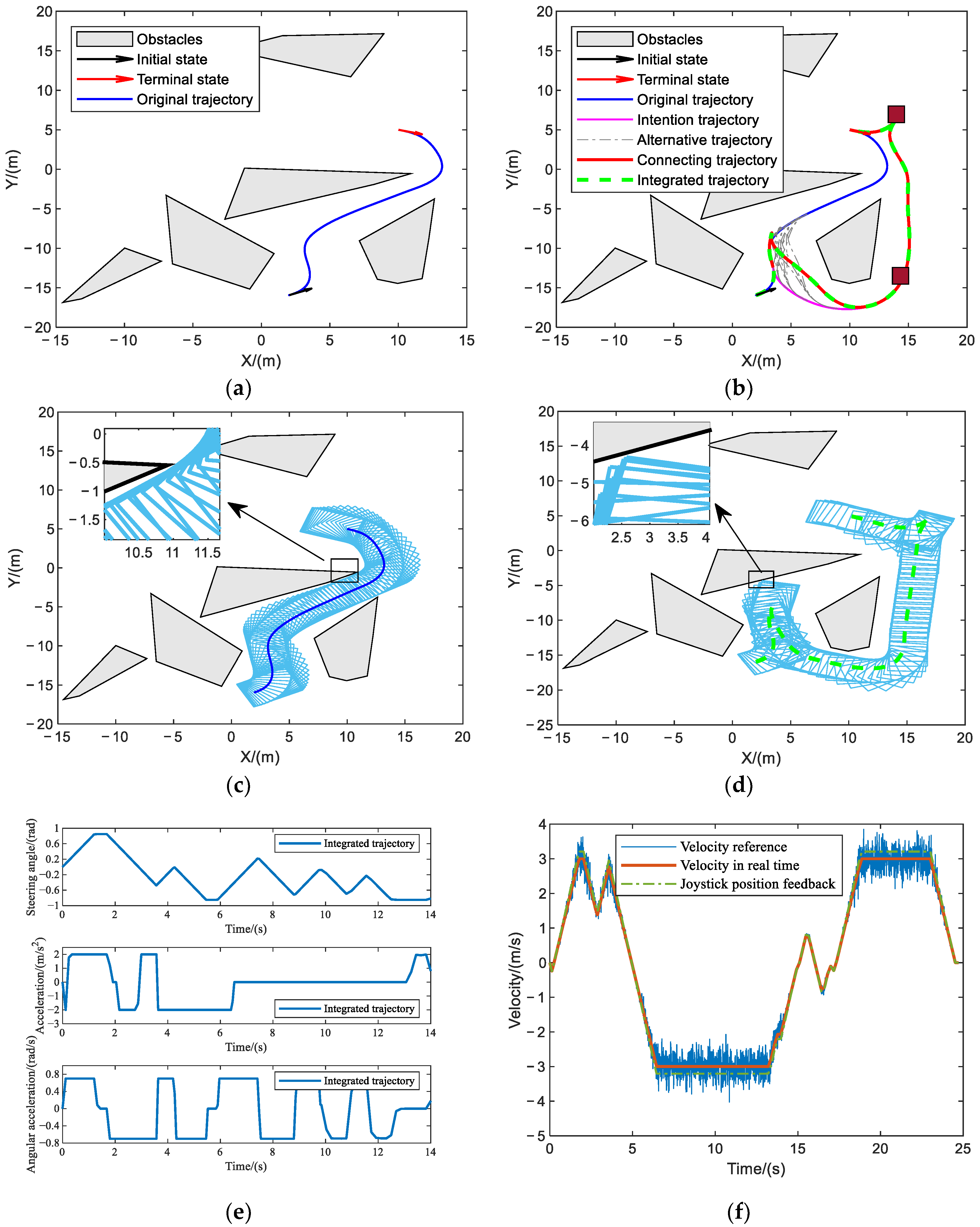
5.3.1. Obstacle Avoidance Verification

Based on the navigation task described in Scenario 1, the optimal control algorithm is used for the trajectory generation, and the shortest running time of the trajectory is taken as the objective function. Figure 7a is the trajectory diagram, where the black arrow represents the initial position and orientation of the vehicle, the red arrow represents the terminal position and orientation of the vehicle, and the blue curve represents the trajectory of the vehicle. Light-gray polygons represent irregularly placed and bulked obstacles. Figure 7b is the footprint of the vehicle, which can illustrate the obstacle avoidance effectiveness of the algorithm more convincingly. The footprint here refers to the vertical projection of the vehicle’s exterior outline onto the ground, geometrically represented as a rectangle. Figure 7c represents the vehicle steering angle, vehicle velocity, and the joystick feedback information. Because the operator is playing a supervisory role in this scenario, there is no speed reference generated by the operation force from the human. The preset maximum linear speed of 3   m / s and the maximum steering angle of 0.85   r a d in Table 1 meet the requirements. Figure 8d represents the acceleration and angular acceleration, which can verify that the solution of the acceleration within the constraint value, where the maximum values are set as 2   m / s 2 and 0.7   r a d / s , respectively. It can be seen that the acceleration solution results of the whole process are all within the preset range.

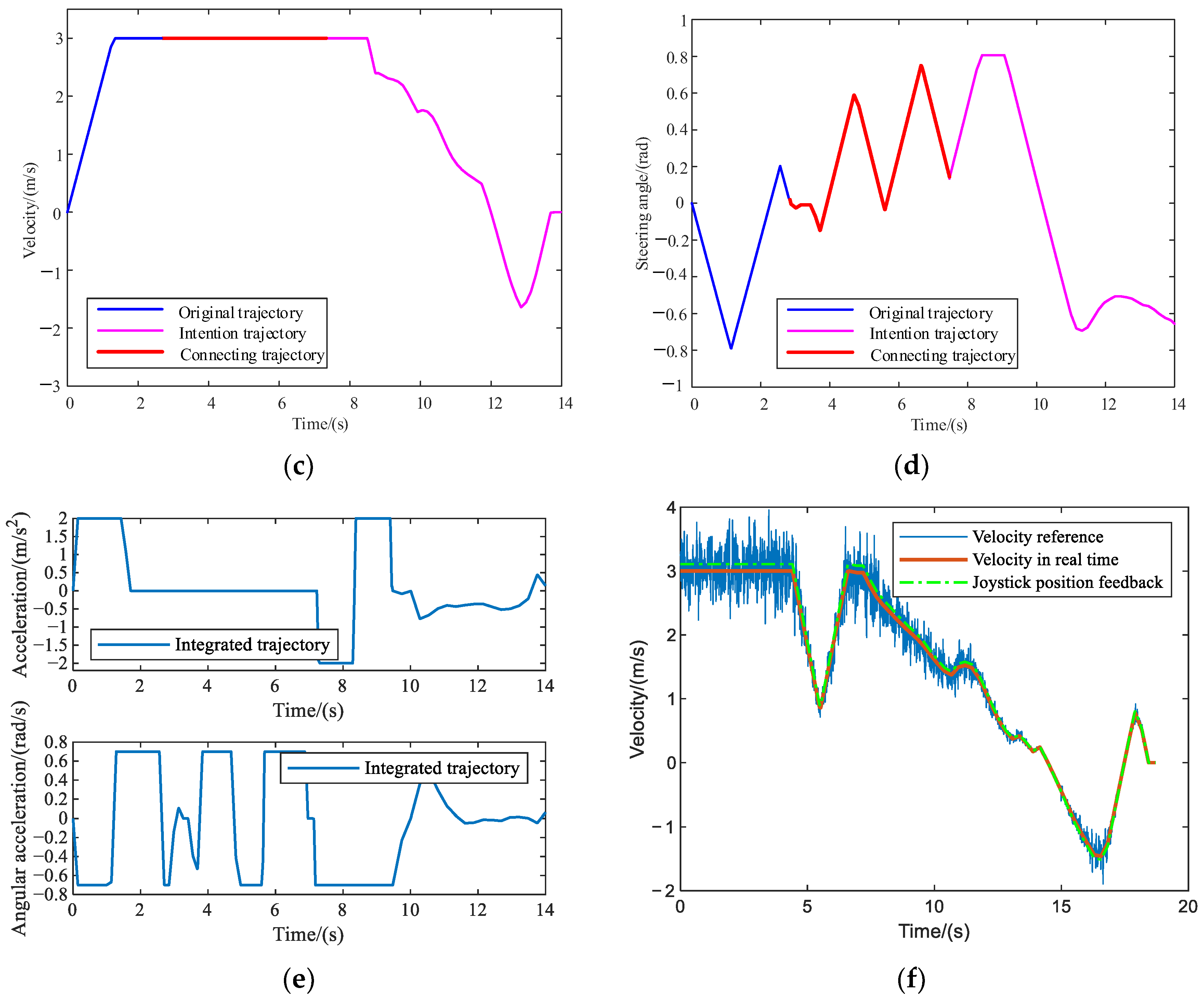
5.3.2. Unified HIR Obstacle Avoidance Verification

As shown in Figure 8, the new obstacle discovery time, t 0 = 2.8205   s , is set in Scenario 2. Figure 8a shows the original trajectory, and the new obstacle is only detected when moving along this trajectory. The dark-gray polygon represents the newly discovered obstacle in Figure 8b. Then, in order to avoid the newly discovered obstacle, the operator redefines the middle target points during the vehicle movement process via the joystick, and the intended trajectory is generated, which is shown as the magenta curve in Figure 8b. At the next moment, appropriate sampling points are selected on the initial trajectory and the intended trajectory to generate a series of alternative trajectories, such as the gray dotted line in Figure 8b, select the trajectory with the shortest time to the connecting trajectory, such as the red curve in Figure 8b, and, finally, connect the original trajectory, connecting trajectory, and the intended trajectory to form an integrated trajectory of the vehicle, as shown in Figure 8b as the bold green dotted line. It can be seen from the schematic diagram of the trajectory that, under the guidance of the human, the purpose of regenerating a feasible trajectory due to the sudden appearance of obstacles during the navigation process of the vehicle is realized, and the new obstacle is perfectly avoided.
As shown in Figure 8c,d, the linear velocity and steering angle information of each stage are extracted, and it can be seen that the addition of the human intention does not cause a sudden change in the vehicle’s steering angle and speed: the values are still within the set range to achieve a smooth transition. The maximum linear velocity preset in Table 1 is 3   m / s , and the maximum steering angle is 0.85   r a d , both of which are met. This verifies that the trajectory generation algorithm based on human intention has certain robustness.
Figure 8e shows the linear acceleration and angular acceleration curves for solving the complete trajectory. The maximum values are set to 2   m / s 2 and 0.7   r a d / s , respectively, the same as Case 1. It can be seen that the acceleration solution results of the whole process are within the preset range. In addition, the simulation data show that the generation of the entire connecting trajectory only takes 3.8657 s, which fully meets the online solution speed requirement of vehicle trajectory generation in an unstructured environment.
In addition to the analysis of the above-mentioned generated trajectory, the haptic information generated by the joystick is also analyzed accordingly, as shown in Figure 8f, where the solid blue line represents the speed reference information transmitted by the human, which is actually obtained by the force/torque sensor installed at the end of the joystick, and then calculates it through the mapping relationship in Formula (1). The solid orange-red line represents the real-time speed information of the vehicle at the slave side, and maps this information to the position information of the joystick at the master side through a certain constant to generate a haptic cue.
From the completion of the navigation task in this scenario, it can be seen that the online heuristic trajectory generation algorithm based on human intention recognition, as proposed in this paper, can help the operator complete navigation tasks in complex/narrow areas and achieve perfect obstacle avoidance. At the same time, the trajectory generator can still obtain a smooth trajectory without sudden changes when the human intention changes, which also shows that the generator has a strong adaptability to change in the human intention. Moreover, the bilateral teleoperation framework proposed in this paper can give the operator certain haptic cues, so that the operator has a certain understanding of the response status of the remote vehicle, providing better balance of the autonomous performance of the vehicle and the subjective control of the operator.

5.3.3. Unified HIR Specific Navigation Verification

As shown in Table 2, the navigation waypoint of the vehicle is changed at t 0 = 2.3797   s , and the vehicle completes navigation tasks with two attitudes of 14.3260 , 8.9915 , 0.1070 and 14.0100 , 0.1847 , 1.9458 . The navigation principle is similar to the obstacle avoidance principle described in Section 5.3.2. The two wine-red boxes in Figure 9b indicate the positions of the two waypoints. Figure 9c,d shows the original trajectory footprint and the corresponding footprint representation after the task is changed; it can obviously be seen that obstacle avoidance can still be achieved in a narrow environment. Figure 9e shows the steering angle, acceleration, and angular acceleration curves calculated by integrated trajectory, and their ranges are within ± 0.85   r a d , ± 2   m / s , and ± 0.7   r a d / s , respectively. Figure 9f shows the speed and related joystick feedback information, and it can be seen from the figure that, after the path point is changed at t 0 = 2.3797   s , the operator also manipulates the joystick to give a certain speed guidance. Correspondingly, the speed information of the vehicle at the slave side is also transmitted to the operator through the joystick, so as to assist the operator to issue instructions at the next moment.

5.4. Parameter Sensitivity Verification

The generation of the connecting trajectory from the original trajectory to the intended trajectory also plays a key role in the whole navigation task. Its generation quality directly determines the tracking performance of the vehicle at the slave end, and the real-time performance of the whole trajectory is also influenced by the connecting trajectory. In this paper, after a change in human intention is discovered and the intended trajectory is available, samples are taken on the initial trajectory and the intended trajectory. Taking the navigation task in Scenario 2 as an example, several sets of simulation experiments are conducted to select the number of sampling points, as shown in Table 3. It can be seen from the simulation data that the algorithm for generating the connection trajectory still has a good performance when the original trajectory sampling points are few. Moreover, increasing the number of sampling points on the original trajectory and the intended trajectory does not reduce the cost function value.

6. Conclusions and Future Work

This paper proposes a shared control scheme for bilateral teleoperation of vehicles with non-holonomic constraints on the ground. The framework is based on admittance control to realize haptic presence, adding the HIR, and establishing HMM to solve the model. Then, according to the results of the HIR, as well as the communication delay in the teleoperation system, the target point of the vehicle’s future travel is formed. Afterwards, the online heuristic trajectory generation scheme based on optimal control is designed. Through the design of simulation experiments, the basic obstacle avoidance function of the trajectory generation module, the adaptability to environmental changes after adding HIR, and the degree of completion after temporarily modifying the navigation task are verified one by one. At the same time, the haptic information transmitted to the joystick gives the operator a certain haptic cue, which also speeds up the completion of the navigation task.
In future work, we will apply this method to actual ground vehicles for real-vehicle experimental verification, and optimize the initial value of the HMM so the number of iterations can be reduced, which can improve the working efficiency of the system. We may also try other model training methods, such as deep reinforcement learning, for HIR.

Author Contributions

Conceptualization, T.N.; methodology, P.Z.; software, P.Z.; validation, P.Z., Z.Z., and C.R.; formal analysis, Z.Z.; investigation, P.Z.; resources, C.R.; data curation, P.Z.; writing—original draft preparation, P.Z.; writing—review and editing, C.R.; visualization, Z.Z.; supervision, T.N.; project administration, T.N.; funding acquisition, T.N. All authors have read and agreed to the published version of the manuscript.

Funding

This research was funded by the Key Research and Development Project of Hebei Province, grant number 21351802D.

Institutional Review Board Statement

Not applicable.

Informed Consent Statement

Not applicable.

Data Availability Statement

Not applicable.

Conflicts of Interest

The authors declare no conflict of interest.

References

  1. Goertz, R.C. Mechanical master-slave manipulator. Nucleonics 1945, 12, 45–46. [Google Scholar]
  2. Clement, G.; Fournier, R.; Gravez, P.; Morillon, J. Computer aided teleoperation: From arm to vehicle control. In Proceedings of the IEEE International Conference on Robotics and Automation, Philadelphia, PA, USA, 24–29 April 1988. [Google Scholar]
  3. Luo, J.; Lin, Z.; Li, Y.; Yang, C. A Teleoperation Framework for Mobile Robots Based on Shared Control. IEEE Robot. Autom. Lett. 2020, 5, 377–384. [Google Scholar] [CrossRef]
  4. Lee, S.; Sukhatme, G.; Kim, G.J.; Park, C.M. Haptic Teleoperation of a Mobile Robot: A User Study. Presence 2005, 14, 345–365. [Google Scholar] [CrossRef]
  5. Hou, X.; Mahony, R.; Schi, F. Comparative Study of Haptic Interfaces for Bilateral Teleoperation of VTOL Aerial Robots. IEEE Trans. Syst. Man Cybern. Syst. 2016, 46, 1352–1363. [Google Scholar] [CrossRef]
  6. Yuan, W.; Li, Z. Brain Teleoperation Control of a Nonholonomic Mobile Robot Using Quadrupole Potential Function. IEEE Trans. Cogn. Dev. Syst. 2019, 11, 527–538. [Google Scholar] [CrossRef]
  7. Ju, C.; Son, H.I. Evaluation of Haptic Feedback in the Performance of a Teleoperated Unmanned Ground Vehicle in an Obstacle Avoidance Scenario. Int. J. Control Autom. Syst. 2019, 17, 168–180. [Google Scholar] [CrossRef]
  8. Li, W.; Ding, L.; Gao, H.; Tavakoli, M. Haptic Tele-Driving of Wheeled Mobile Robots Under Nonideal Wheel Rolling, Kinematic Control and Communication Time Delay. IEEE Trans. Syst. Man Cybern. Syst. 2020, 50, 336–347. [Google Scholar] [CrossRef]
  9. Lam, T.M.; Boschloo, H.W.; Mulder, M.; Van Paassen, M.M. Artificial Force Field for Haptic Feedback in UAV Teleoperation. IEEE Trans. Syst. Man Cybern. Part A Syst. Hum. 2009, 39, 1316–1330. [Google Scholar] [CrossRef]
  10. Courtois, H.; Aouf, N. Haptic Feedback for Obstacle Avoidance Applied to Unmanned Aerial Vehicles. In Proceedings of the International Conference on Unmanned Aircraft Systems (ICUAS’17), Miami, FL, USA, 13–16 June 2017. [Google Scholar]
  11. Lin, Z.; Luo, J.; Yang, C. A Teleoperated Shared Control Approach with Haptic Feedback for Mobile Assistive Robot. In Proceedings of the 25th International Conference on Automation and Computing (ICAC), Lancaster, UK, 5–7 September 2019. [Google Scholar]
  12. Han, H.; Kim, C.; Lee, D.Y. Collision Avoidance for Haptic Master of Active-Steering Catheter Robot. In Proceedings of the 19th International Conference on Control, Automation and Systems (ICCAS), Jeju, Republic of Korea, 19–22 April 2019. [Google Scholar]
  13. Pruks, V.; Ryu, J.-H. Method for generating real-time interactive virtual fixture for shared teleoperation in unknown environments. Int. J. Robot. Res. 2022, 41, 925–951. [Google Scholar] [CrossRef]
  14. Luo, J.; Yang, C.; Wang, N.; Wang, M. Enhanced teleoperation performance using hybrid control and virtual fixture. Int. J. Syst. Sci. 2019, 50, 451–462. [Google Scholar] [CrossRef]
  15. Feng, H.; Yin, C.; Li, R.; Ma, W.; Yu, H.; Cao, D.; Zhou, J. Flexible virtual fixtures for human-excavator cooperative system. Autom. Constr. 2019, 106, 102897. [Google Scholar] [CrossRef]
  16. Yoon, H.U.; Wang, R.F.; Hutchinson, S.A.; Hur, P. Customizing haptic and visual feedback for assistive human–robot interface and the effects on performance improvement. Robot. Auton. Syst. 2017, 91, 258–269. [Google Scholar] [CrossRef]
  17. Kong, H.; Yang, C.; Li, G.; Dai, S.L. A sEMG-Based Shared Control System with No-Target Obstacle Avoidance for Omnidirectional Mobile Robots. IEEE Access 2020, 8, 26030–26040. [Google Scholar] [CrossRef]
  18. Chicaiza, F.A.; Slawiñski, E.; Salinas, L.R.; Mut, V.A. Evaluation of Path Planning with Force Feedback for Bilateral Teleoperation of Unmanned Rotorcraft Systems. J. Intell. Robot. Syst. 2022, 105, 34. [Google Scholar] [CrossRef]
  19. Hou, X. Haptic teleoperation of a multirotor aerial robot using path planning with human intention estimation. Intell. Serv. Robot. 2021, 14, 33–46. [Google Scholar] [CrossRef]
  20. Masone, C.; Mohammadi, M.; Giordano, P.R.; Franchi, A. Shared planning and control for mobile robots with integral haptic feedback. Int. J. Robot. Res. 2018, 37, 1395–1420. [Google Scholar] [CrossRef]
  21. Jiang, S.-Y.; Lin, C.-Y.; Huang, K.-T.; Song, K.-T. Shared Control Design of a Walking-Assistant Robot. IEEE Trans. Control Syst. Technol. 2017, 25, 2143–2150. [Google Scholar] [CrossRef]
  22. Zhang, H.-Y.; Lin, W.-M.; Chen, A.-X. Path Planning for the Mobile Robot: A Review. Symmetry 2018, 10, 450. [Google Scholar] [CrossRef]
  23. Martins, O.O.; Adekunle, A.A.; Adejuyigbe, S.B.; Adeyemi, O.H.; Arowolo, M.O. Wheeled Mobile Robot Path Planning and Path Tracking Controller Algorithms: A Review. J. Eng. Sci. Technol. Rev. 2020, 13, 152–164. [Google Scholar] [CrossRef]
  24. Li, B.; Acarman, T.; Zhang, Y.; Ouyang, Y.; Yaman, C.; Kong, Q.; Zhong, X.; Peng, X. Optimization-Based Trajectory Planning for Autonomous Parking with Irregularly Placed Obstacles: A Lightweight Iterative Framework. IEEE Trans. Intell. Transp. Syst. 2022, 23, 11970–11981. [Google Scholar] [CrossRef]
  25. Li, B.; Ouyang, Y.; Li, X.; Cao, D.; Zhang, T.; Wang, Y. Mixed-integer and Conditional Trajectory Planning for an Autonomous Mining Truck in Loading/Dumping Scenarios: A Global Optimization Approach. IEEE Trans. Intell. Veh. 2022, 8, 1512–1522. [Google Scholar] [CrossRef]
  26. Chen, K.; Zhang, H. Design of Synchronization Tracking Adaptive Control for Bilateral Teleoperation System with Time-Varying Delays. Sensors 2022, 22, 7798. [Google Scholar] [CrossRef] [PubMed]
  27. Zhang, H.; Song, A.; Li, H.; Chen, D.; Fan, L. Adaptive Finite-Time Control Scheme for Teleoperation with Time-Varying Delay and Uncertainties. IEEE Trans. Syst. Man Cybern. Syst. 2022, 52, 1552–1566. [Google Scholar] [CrossRef]
  28. Wang, H. Bilateral control of teleoperator systems with time-varying delay. Automatica 2021, 134, 109707. [Google Scholar] [CrossRef]
  29. Sheridan, T.B. Telerobotics. Automatica 1987, 25, 487–507. [Google Scholar] [CrossRef]
  30. Kleinsmith, A.; Bianchi-Berthouze, N. Affective Body Expression Perception and Recognition: A Survey. IEEE Trans. Affect. Comput. 2013, 4, 15–33. [Google Scholar] [CrossRef]
  31. Wang, Q.; Jiao, W.; Yu, R.; Johnson, M.T.; Zhang, Y. Virtual Reality Robot-Assisted Welding Based on Human Intention Recognition. IEEE Trans. Autom. Sci. Eng. 2020, 17, 799–808. [Google Scholar] [CrossRef]
  32. Huang, J.; Huo, W.; Xu, W.; Mohammed, S.; Amirat, Y. Control of Upper-Limb Power-Assist Exoskeleton Using a Human-Robot Interface Based on Motion Intention Recognition. IEEE Trans. Autom. Sci. Eng. 2015, 12, 1257–1270. [Google Scholar] [CrossRef]
  33. Morelli, L.; Guadagni, S.; Di Franco, G.; Palmeri, M.; Di Candio, G.; Mosca, F. Da Vinci single site© surgical platform in clinical practice: A systematic review. Int. J. Med. Robot. Comput. Assist. Surg. 2016, 12, 724–734. [Google Scholar] [CrossRef]
  34. Li, Y.; Ge, S.S. Human-robot collaboration based on motion intention estimation. IEEE/ASME Trans. Mechatron. 2014, 19, 1007–1014. [Google Scholar] [CrossRef]
  35. Kelley, R.; Tavakkoli, A.; King, C. Understanding Human Intentions via Hidden Markov Models in Autonomous Mobile Robots. In Proceedings of the ACM/IEEE International Conference on Human-Robot Interaction, Amsterdam, The Netherlands, 7–10 March 2008. [Google Scholar]
  36. Petković, T.; Puljiz, D.; Marković, I.; Björn, H. Human intention estimation based on Hidden Markov Model Motion validation for safe flexible robotized warehouses. Robotics 2019, 57, 182–196. [Google Scholar] [CrossRef]
  37. Liu, T.; Lyu, E.; Wang, J.; Meng, M.Q.-H. Unified Intention Inference and Learning for Human–Robot Cooperative Assembly. IEEE Trans. Autom. Sci. Eng. 2022, 19, 2256–2266. [Google Scholar] [CrossRef]
  38. Aarno, D.; Kragic, D. Layered HMM for motion intention recognition. In Proceedings of the IEEE/RSJ International Conference on Intelligent Robots and Systems, Beijing, China, 9–15 October 2006. [Google Scholar]
  39. Koert, D.; Trick, S.; Ewerton, M.; Lutter, M.; Peters, J. Incremental learning of an open-ended collaborative skill library. Int. J. Hum. Robot. 2020, 17, 2050001. [Google Scholar] [CrossRef]
  40. Kelley, R.; Tavakkoli, A.; King, C.; Ambardekar, A.; Nicolescu, M.; Nicolescu, M. Context-Based Bayesian Intent Recognition. IEEE Trans. Auton. Ment. Dev. 2012, 4, 215–225. [Google Scholar] [CrossRef]
  41. Bachman, P.; Milecki, A. Investigation of electrohydraulic drive control system with the haptic joystick. Acta Mech. Autom. 2018, 12, 5–10. [Google Scholar] [CrossRef]
  42. Hogan, N. Impedance control: An approach to manipulation: Part I–Theory. J. Dyn. Syst. Meas. Control 1985, 107, 1–7. [Google Scholar] [CrossRef]
  43. Na, U.J. A new impedance force control of a haptic teleoperation system for improved transparency. J. Mech. Sci. Technol. 2017, 31, 6005–6017. [Google Scholar] [CrossRef]
  44. Michel, Y.; Rahal, R.; Pacchierotti, C.; Giordano, P.R.; Lee, D. Bilateral Teleoperation with Adaptive Impedance Control for Contact Tasks. IEEE Robot. Autom. Lett. 2021, 6, 5429–5436. [Google Scholar] [CrossRef]
  45. Estrada, E.; Yu, W.; Li, X. Stability and transparency of delayed bilateral teleoperation with haptic feedback. Int. J. Appl. Math. Comput. Sci. 2019, 29, 681–692. [Google Scholar] [CrossRef]
  46. Yang, C.; Peng, G.; Cheng, L.; Na, J.; Li, Z. Force Sensorless Admittance Control for Teleoperation of Uncertain Robot Manipulator Using Neural Networks. IEEE Trans. Syst. Man Cybern. Syst. 2021, 51, 3282–3292. [Google Scholar] [CrossRef]
  47. Kimura, S.; Nozaki, T.; Murakami, T. Admittance Control-based Bilateral Control System Considering Position Error. In Proceedings of the IEEE International Conference on Mechatronics, Kashiwa, Japan, 7–9 March 2021. [Google Scholar]
  48. Grewal, J.K.; Krzywinski, M.; Altman, N. Markov models—Hidden Markov models. Nat. Methods 2019, 16, 795–796. [Google Scholar] [CrossRef] [PubMed]
  49. Li, B.; Yin, Z.; Ouyang, Y.; Zhang, Y.; Zhong, X.; Tang, S. Online Trajectory Replanning for Sudden Environmental Changes during Automated Parking: A Parallel Stitching Method. IEEE Trans. Intell. Veh. 2022, 7, 748–757. [Google Scholar] [CrossRef]
Figure 1. Joystick configuration.
Machines 11 00528 g001
Figure 2. System configuration.
Machines 11 00528 g002
Figure 3. Hidden state number identification: (a) Intention discretization; (b) The number of hidden states.
Machines 11 00528 g003
Figure 4. HMM training process: (a) Iteration 0; (b) Iteration 56.
Machines 11 00528 g004
Figure 5. The construction of vehicle obstacle avoidance model: (a) Double-circle model; (b) Obstacle avoidance constraint.
Machines 11 00528 g005
Figure 6. Schematic diagram of online heuristic trajectory generation.
Machines 11 00528 g006
Figure 7. The experimental results in Case 1: (a) Vehicle trajectory; (b) Vehicle footprint; (c) Steering angle and feedback generation results; (d) Acceleration and angular acceleration results.
Machines 11 00528 g007
Figure 8. The experimental results in Case 2: (a) Original trajectory; (b) Overall trajectory; (c) velocity; (d) Steering angle; (e) Acceleration and angular acceleration results; (f) Feedback generation results.
Machines 11 00528 g008aMachines 11 00528 g008b
Figure 9. The experimental results in Case 3: (a) Original trajectory; (b) Overall trajectory; (c) Original footprints; (d) Overall footprints; (e) Trajectory variable results; (f) Feedback generation results.
Machines 11 00528 g009
Table 1. Vehicle basic parameter settings.
ParametersDescriptionValuesParametersDescriptionValues
N Front overhang of the vehicle0.9600 m v m a x Maximum velocity3.00 m/s
M Rear overhang of the vehicle0.9290 m a m a x Maximum acceleration2.00 m/s2
L Length of the vehicle2.8000 m ϕ m a x Maximum steering angle0.85 rad
B Width of the vehicle1.9420 m ω m a x Maximum angular acceleration0.70 rad/s
Table 2. Navigation tasks.
Case Index x 0 , y 0 , θ 0 x t f , y t f , θ t f t 0 Middle Goal Position
1 9.7614 , 11.5208 , 5.7537 1.3009 , 8.7921 , 5.6629
2 15.6103 , 11.6961 , 3.3648 8.1540 , 1.5118 , 5.8547 2.8205   s
3 2.0485 , 15.9200 , 5.8106 10.0142 , 4.9988 , 3.4627 2.3797   s 14.3260 , 8.9915 , 0.1070
14.0100 , 0.1847 , 1.9458
Table 3. Parameter sensitivity verification.
The Number of Sampling PointsCost Function ValueThe Number of Sampling PointsCost Function Value
N o r i g i n a l = 1 ; N i n t e n t i o n = 3 13.4343 s N o r i g i n a l = 5 ; N i n t e n t i o n = 3 12.4590 s
N o r i g i n a l = 1 ; N i n t e n t i o n = 6 16.3493 s N o r i g i n a l = 5 ; N i n t e n t i o n = 6 13.0369 s
N o r i g i n a l = 3 ; N i n t e n t i o n = 6 14.3939 s N o r i g i n a l = 5 ; N i n t e n t i o n = 9 12.8421 s
N o r i g i n a l = 3 ; N i n t e n t i o n = 9 15.8179 s N o r i g i n a l = 5 ; N i n t e n t i o n = 20 13.2860 s
Disclaimer/Publisher’s Note: The statements, opinions and data contained in all publications are solely those of the individual author(s) and contributor(s) and not of MDPI and/or the editor(s). MDPI and/or the editor(s) disclaim responsibility for any injury to people or property resulting from any ideas, methods, instructions or products referred to in the content.

