Article

A Wearable Upper Limb Exoskeleton for Intuitive Teleoperation of Anthropomorphic Manipulators

1
State Key Laboratory of Robotics, Shenyang Institute of Automation, Chinese Academy of Sciences, Shenyang 110169, China
2
Institutes for Robotics and Intelligent Manufacturing, Chinese Academy of Sciences, Shenyang 110169, China
3
University of Chinese Academy of Sciences, Beijing 101408, China
*
Author to whom correspondence should be addressed.
Machines 2023, 11(4), 441; https://doi.org/10.3390/machines11040441
Submission received: 8 March 2023 / Revised: 28 March 2023 / Accepted: 29 March 2023 / Published: 30 March 2023
(This article belongs to the Section Robotics, Mechatronics and Intelligent Machines)

Abstract

:
Teleoperation technology combines the strength and accuracy of robots with the perception and cognition abilities of human experts, allowing the robots to work as an avatar of the operator in dangerous environments. The motion compatibility and intuitiveness of the human–machine interface directly affect the quality of teleoperation. However, many motion capture methods require special working environments or need bulky mechanisms. In this research, we proposed a wearable, lightweight, and passive upper limb exoskeleton, which takes intuitiveness and human-machine compatibility as a major concern. The upper limb pose estimation and teleoperation mapping control methods based on the exoskeleton are also discussed. Experimental results showed that by the help of the upper limb exoskeleton, people can achieve most areas of the normal range of motion. The proposed mapping control methods were verified on a 14-DOF anthropomorphic manipulator and showed good performance in teleoperation tasks.

1. Introduction

Over the last few decades, robots have been replacing humans in many scenarios, relieving people of heavy physical labor and harmful jobs. Although the rapid evolution of artificial intelligence (AI) enables the robot to work in an autonomous fashion, there are still many situations in which robots need to be teleoperated by humans, such as working in unstructured environments or critical tasks in which failures are intolerable. Especially in dangerous scenarios such as chemical plants [1], disaster sites [2], explosives demolition [3], or space exploration [4], teleoperated robots are still the most reasonable and practical solution for working as remote avatars of human operators.
The human-machine interface plays an important role in teleoperation. The intuitiveness of the human-machine interface directly affects the transparency between the operator and the slave robot. Keyboards and joysticks are the most common human-machine interface, which are easy to use to provide simple commands in teleoperation tasks [5,6]. However, the degree of freedom (DOF) available from such devices is usually much smaller than the task space dimensions. So, they can be used for very limited slave devices, while the lack of DOFs also challenges the space perception of the operator. Haptic devices like PHANTOM [7] and Force Dimension SIGMA [8] are also frequently used as master devices in teleoperation, which can provide force feedback while measuring the operator’s motion commands. Although the physical feedback improves the interactivity in teleoperation, the range of motion for such devices is often very limited, which decreases the accuracy and intuitiveness of controlling human-scale slave devices.
The above methods only generate a control command for the end-effectors of the slave robots. However, for complex slave devices like anthropomorphic robots, the human–machine interface is required to provide more information than only the end-effector pose. In contrast, directly capturing the body motion is more convenient and intuitive for controlling the whole body of anthropomorphic robots, which is very friendly to nonprofessional users. Optical motion capture technology was used to control the NAO humanoid robot to mimic the human operator [9]. The RGBD cameras like Microsoft Kinect can extract the skeleton status of the human body and map it into robot-control commands [10,11]. Most optical or camera-based motion capture devices are sensitive to illumination conditions, which limits application to indoor environments. In addition, fixed installation of the camera or tracker is mandatory. The body pose can also be measured by attaching a set of IMU sensors and used as the master side control commands [12,13]. The IMU sensors are lightweight and easy to install, which can overcome the environmental limitations of camera and optical devices. However, the positions of installation on the body do not result in them being accurately identical every time. Therefore, calibration and correction algorithms are needed before use while the inevitable shifting over time problem of the inertial components makes it unsuitable for long time, high accuracy, and high-reliability teleoperations.
Exoskeletons have been widely used in rehabilitation [14,15] and motion assistance [16,17,18]. Recently, research studies on exoskeletons have also been extended to master devices for teleoperation. Many exoskeleton devices [19,20,21,22] have been developed to acquire upper limb postures and perform master-slave teleoperation. Compared with the previously discussed motion measurement methods, the exoskeleton does not require a special environment and installation. The rigid body structures also guarantee measurement accuracy and are calibration free. Force feedback features were applied in some previous studies [19,21], which improve the presence of the operator. Meanwhile, the motors, transmission mechanism, and high-capacity battery make the system too bulky to be worn by humans for a long time.
So, in this research, we proposed to develop a wearable, lightweight, and passive upper limb exoskeleton, which is comfortable to wear and provides an intuitive human-machine interface for the teleoperation control of anthropomorphic manipulators. A prototype of the developed exoskeleton is illustrated in Figure 1. We first analyzed the motion of the upper limbs and established a simplified 7-DOF kinematic model of the upper limb. Then we elaborated on the mechanism design and the data acquisition and transmission methods of the exoskeleton system. To overcome the challenges in making the shoulder mechanism compact and compatible with human motions, we developed a spherical scissor mechanism to mitigate the limitation in range of motion. For the teleoperation of the anthropomorphic manipulators, we devised joint space and task space mapping control strategies based on the proposed exoskeleton device. The pros and cons of the two methods are also discussed. Finally, we conducted a series of experiments to verify the human-machine compatibility of the exoskeleton mechanism and the performance of the mapping control methods.
The major contributions of this work can be summarized as follows.
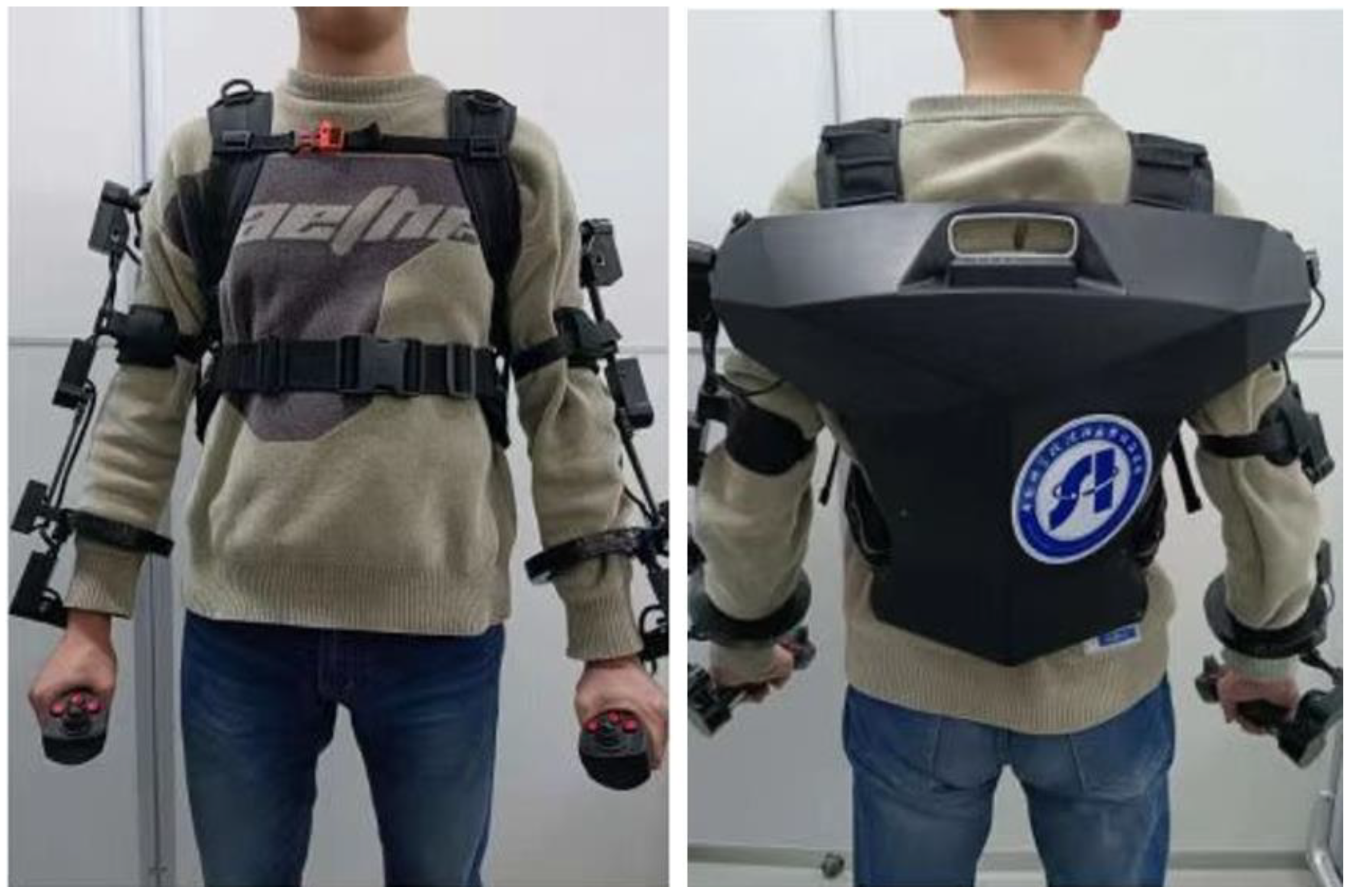
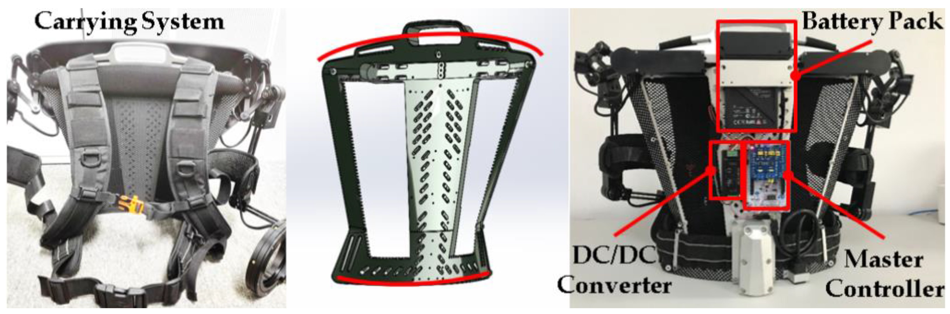
  • We present a complete solution for measuring precisely upper limb posture with a wearable exoskeleton device. Compared with existing works in [19,20,21,22], our exoskeleton can be steadily fixed on the torso by the curved back frame and carrying system, which provides self-alignment capabilities and guarantees measurement accuracy.
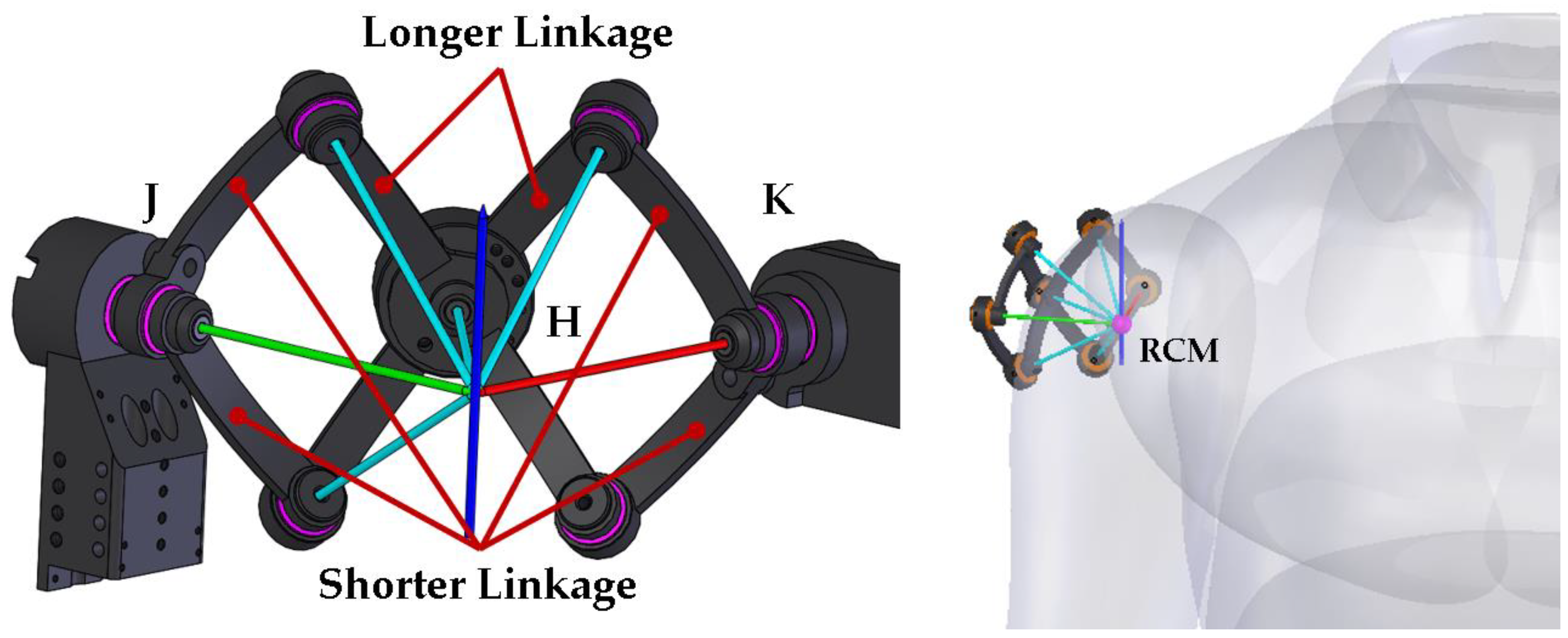
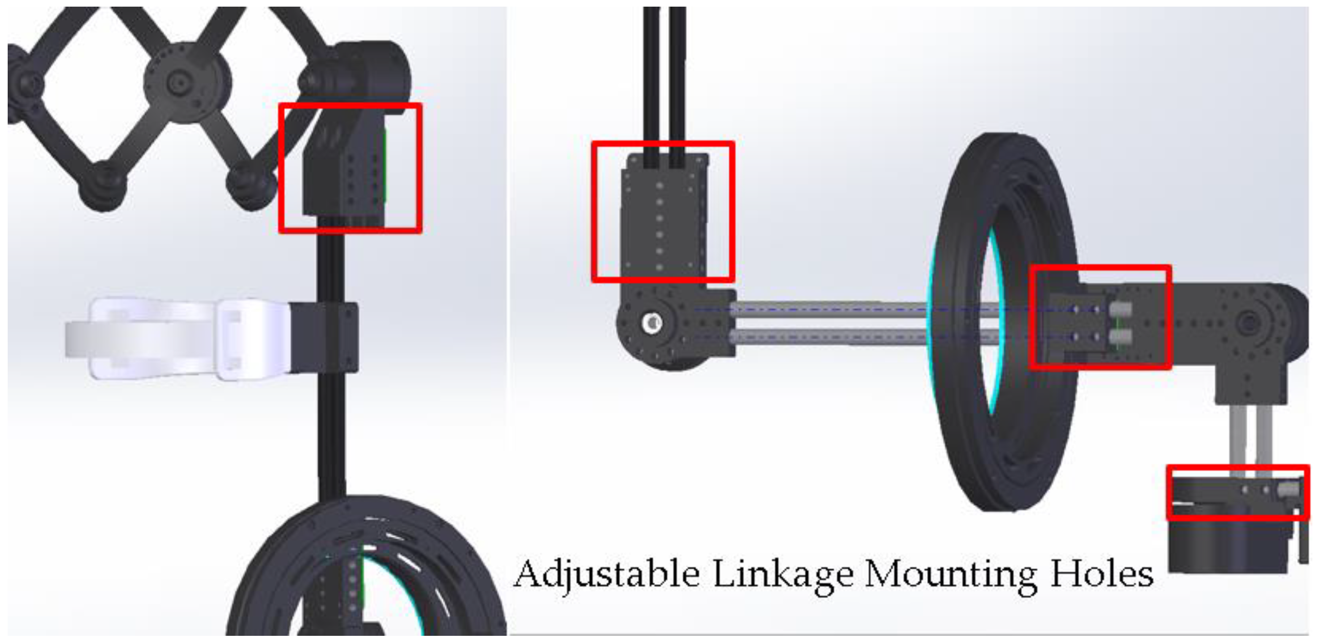
  • We seek to make a balance between the complexity and human-machine compatibility of the device. A spherical scissor mechanism is proposed for the exoskeleton shoulder to maximize the device’s range of motion without making the system bulky. The overall mass of the device is only 4.8 kg, which is lighter than most existing similar devices.
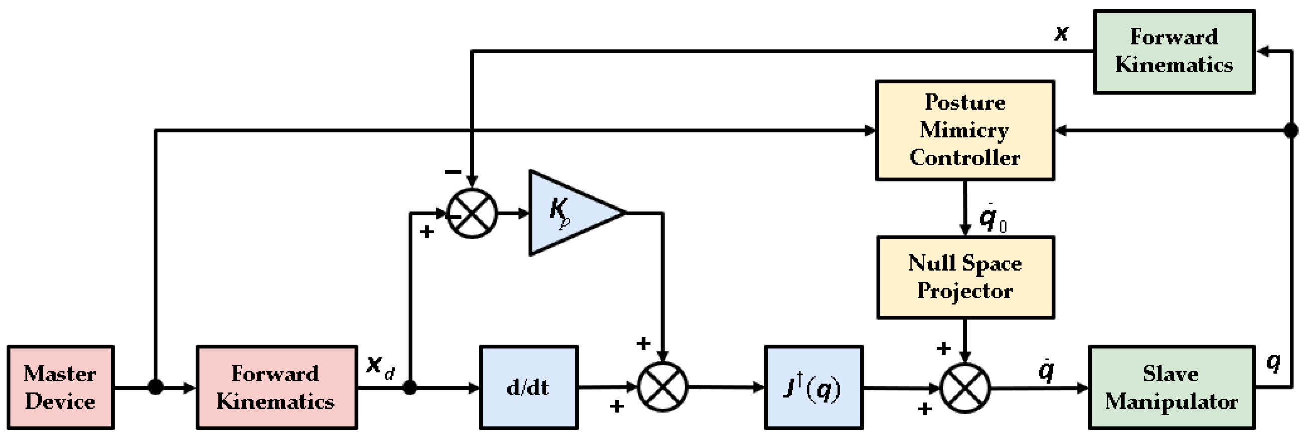
  • We provide both joint space and task space control strategies for performing teleoperation of anthropomorphic manipulators with the exoskeleton device. The flexible control strategies allow the exoskeleton to adapt to different types of slave devices and application requirements.

2. Design and Implementation

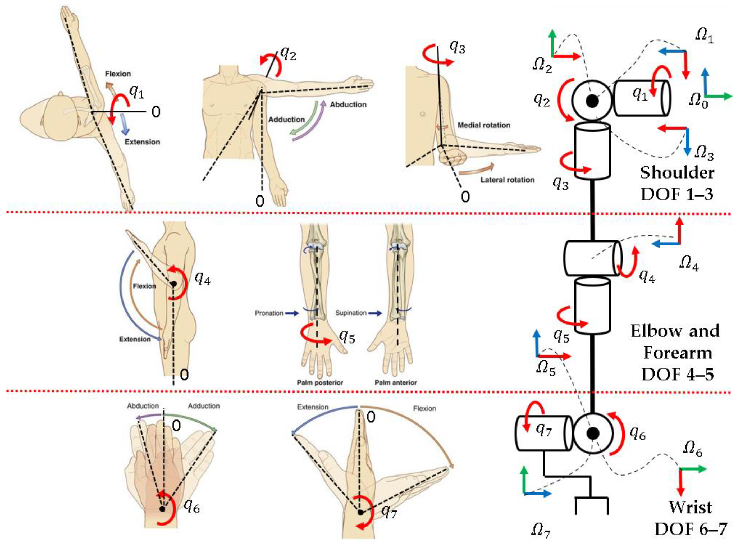
2.1. Upper Limb Motions and Modeling

The upper limb is the most dexterous part of the human body which can generate very complex motions. Master devices for teleoperation measure the upper limb status in real time, and the data can be used to recover the upper limb posture. So, a basic understanding of the motions of the upper limb and establishing a simplified model are essential.
The motions of the upper limb have been studied for a long time in human kinesiology fields. It is well acknowledged that the upper limb motions can be described with seven rotational DOFs [23,24], including three DOFs at the glenohumeral (GH) joint, one DOF at the elbow joint, three DOFs at the forearm and the wrist joints. The motion patterns are presented on the left side of Figure 2.
In research [26], ranges of the seven basic motions of normal people have been studied (Table 1), which are an important reference in determining the mechanical specifications of the exoskeleton. If the exoskeleton seriously reduced the range of motion in some DOFs, the wearer could feel uncomfortable and have difficulty in performing teleoperation.
According to the motion patterns and the positions of the rotational joints, we model the upper limb as a 7-DOF serial structure as depicted on the right side of Figure 2.

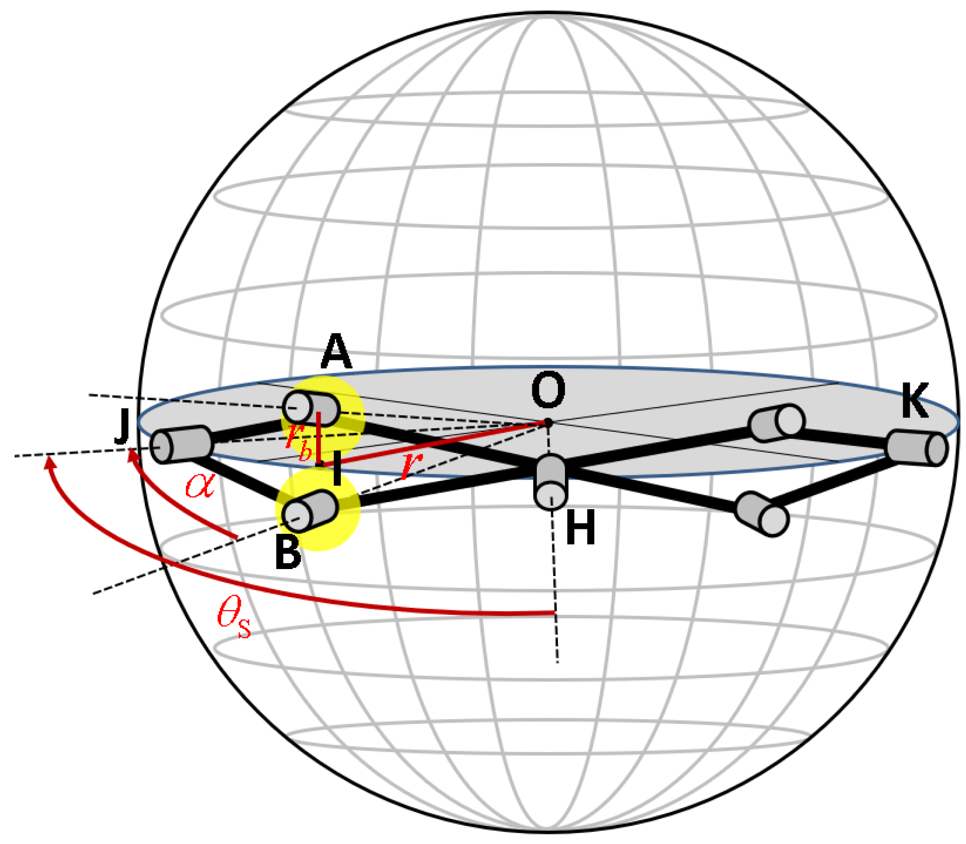
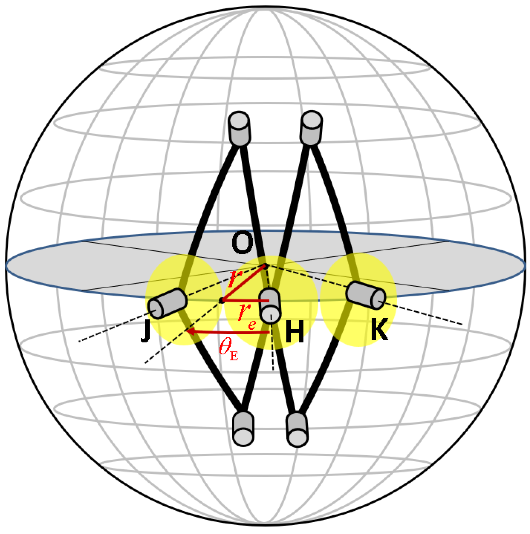
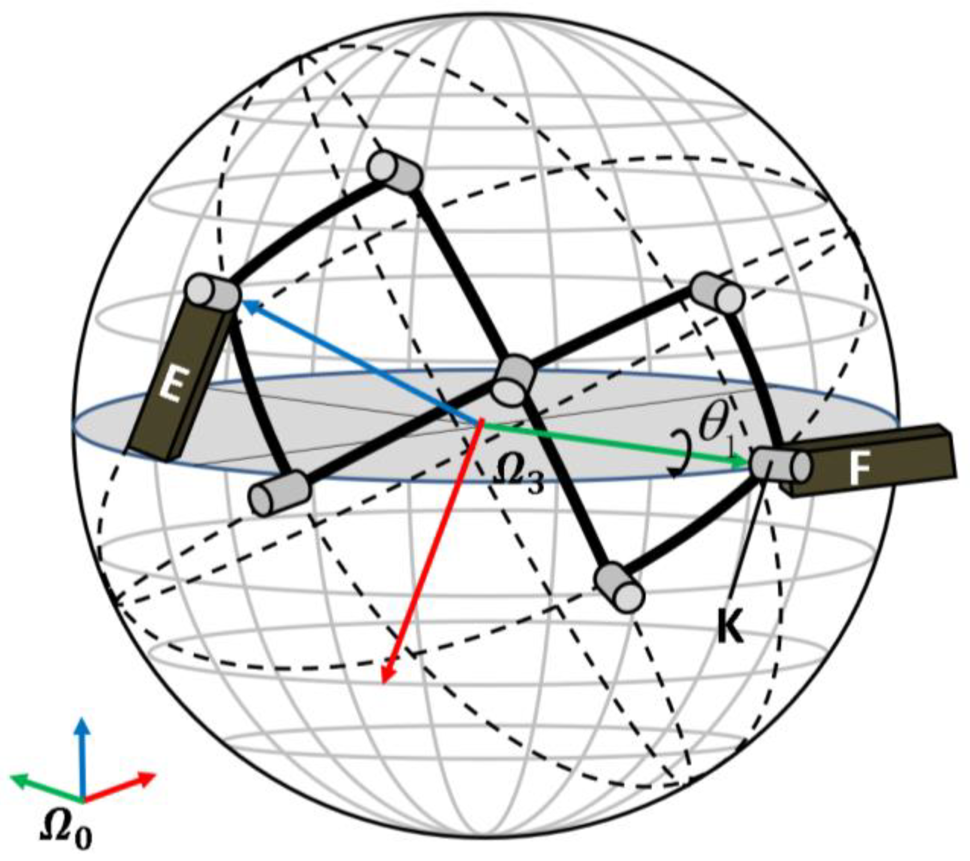
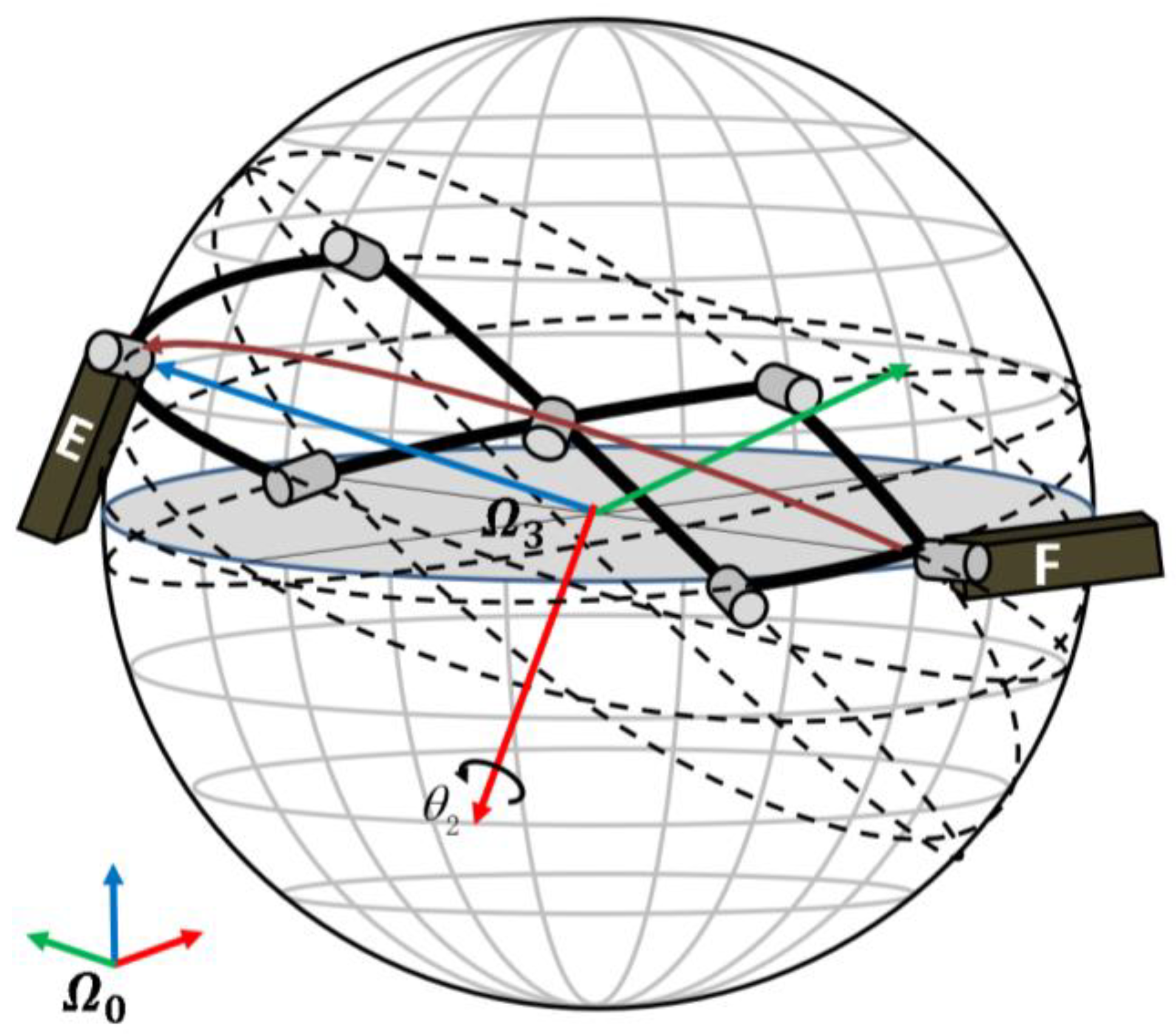
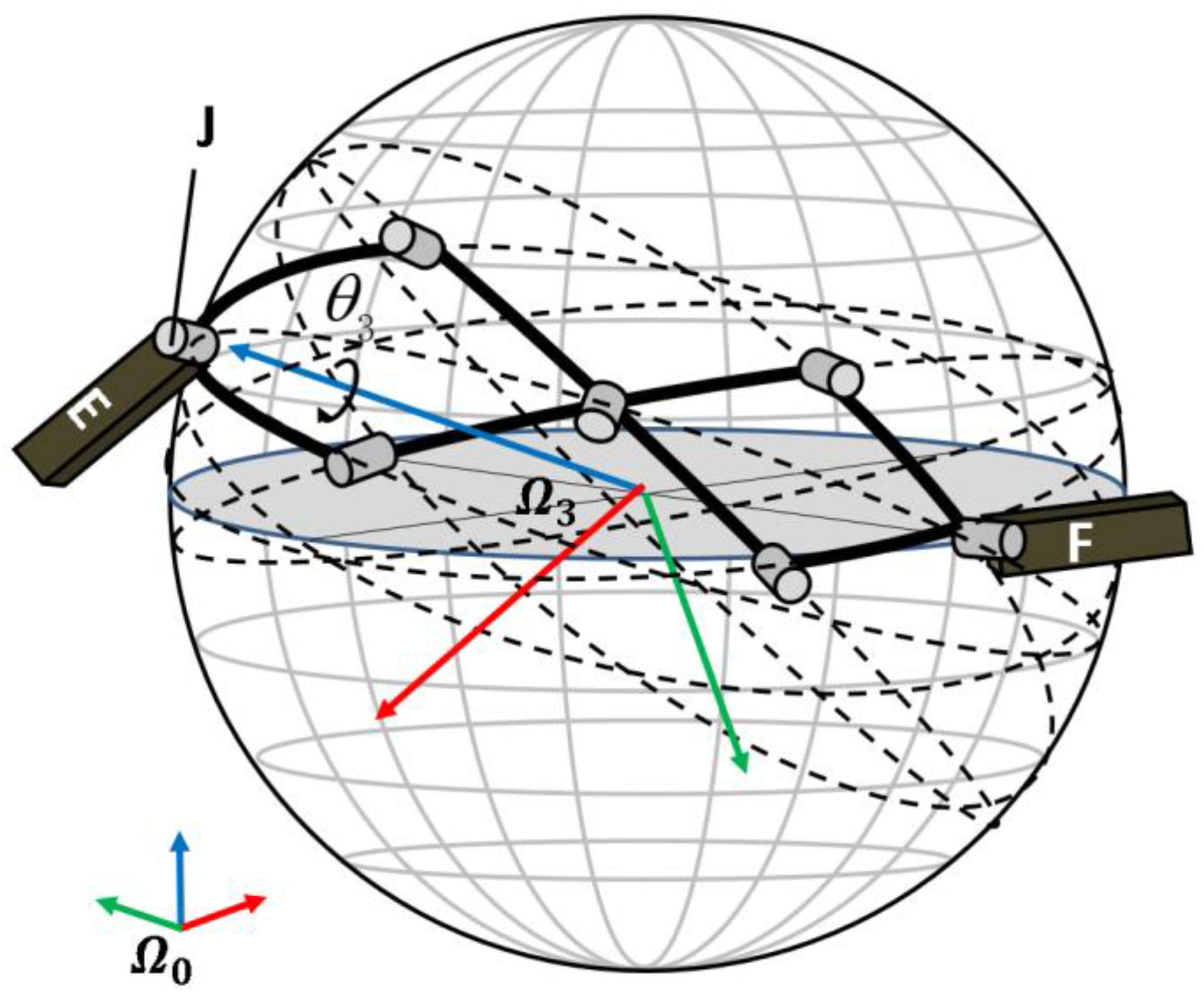
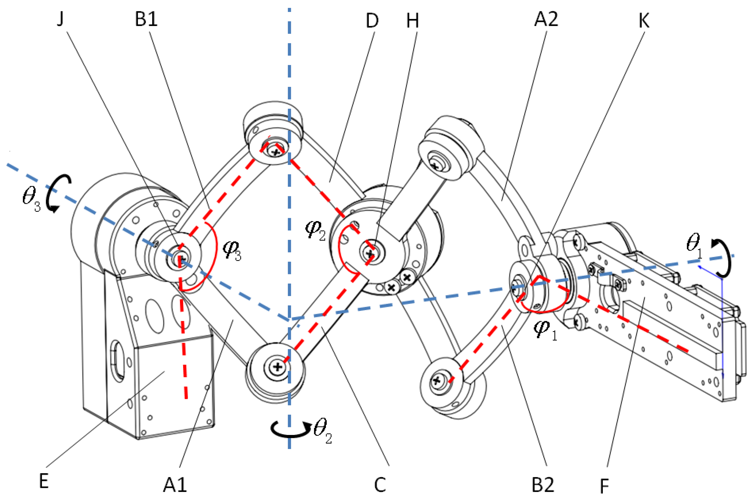
2.2. Shoulder Mechanism

Functionally, we use the simplified 3-DOF serial model to describe the main rotational motions (flexion/extension, medial/lateral rotation, and abduction/adduction) of the human GH joint.
The axes of the three rotational joints are perpendicular to each other and converge at the same point, which is located at the inside of the human arm. Aligning the central point of the rotational joints to the rotation center of the GH joint is significant for improving comfortability and accuracy for posture measurement. The shoulder mechanism connects the upper arm link to the base frame on the back. However, the rotational center of the human GH joint is surrounded by bones, muscles, and skin. The body tissues occupy too much working space, which makes it challenging to design the shoulder mechanism of the exoskeleton. Many previous research studies on upper limb exoskeletons made efforts to improve the comfortability of shoulder motions. One solution is to enlarge the working radius of the shoulder mechanism to keep it away from the human body. Another idea is to increase the DOFs to improve the matching degree for human motions. Research studies [22,27] propose using 5–6 DOFs to fit the shoulder motions. However, these methods lead to bulky and complex mechanisms, rising weight, costs, and difficulty in modeling and control.
The scissor mechanism is deployable in space and has been long used for the lifting mechanism. The scissor mechanism with curved linkages is a variant of traditional ones, which can be deployed and folded on the surface of a sphere. So, it is especially suitable for the exoskeleton shoulder mechanism, where compactness and lightweight are desired. The concept of a scissor mechanism with curved linkages has been used on the shoulder part of rehabilitation devices [28,29,30].
In this research, a 3-DOF spherical scissor mechanism was designed for the exoskeleton shoulder. The spherical scissor mechanism reduces space occupation and weight and also makes mobility compatible with the range of motion of normal people as listed in Table 1.
As dedepicted in Figure 3, the spherical scissor mechanism is composed of six curved linkages and seven common joints. The two longer curved linkages have twice the arc length of the shorter curved linkages. Three 17-bit absolute encoders (Netzer, DS-25, Misgav, Israel) are installed on joints J, K, and H to measure the rotational angles. The axes of all the joints pass through the same point at the sphere center, which is referred as the remote center of motion, or RCM. To make the spherical scissor mechanism properly compatible with the shoulder motions, the RCM of the joints should be configured near the rotational center of the GH joint of the human body as much as is possible. Every curved linkage of the mechanism is an arc between the joints at its two ends on the great circle. All the curved linkages have the same radius. The above conditions guarantee the spherical scissor assembly always moves on the surface of the sphere.
In the development of a practical prototype, the mechanical specifications should be determined. The radius of the mechanism working sphere should be compatible with the wearer’s physical measurements. By measuring the armhole size of a set of subjects, the radius of the sphere occupied by bones, muscles, and skin around the shoulder is estimated to be about 60 mm on average. Considering the possible translation of the GH joint center [31] and the thickness of the clothes, we set the radius of the mechanism working sphere as 100 mm.
The curvature angle of each linkage will affect the range of the medial/lateral motions. Ideally, the curvature angle of the fully folded and fully deployed mechanism should be zero and twice the curvature angle of the longer linkage respectively. However, because some of the space is occupied by bearings and encoders in a practical mechanism, the adjacent linkages cannot completely overlap in the above extreme conditions.
As depicted in Figure 4, the pitch angle is defined as the span of a single rhombus of the spherical scissor mechanism. When fully deployed (Figure 4), θ S is limited by the collision of the bearings installed at joint A and joint B. The point I is defined as the intersection of the arc between AB and the equator of the sphere. When the bearings at joint A and joint B collide, the curvature angle from A to I is approximate to r b / r , where r b is the radius of the bearings and r is the radius of the working sphere. The curvature angle of the shorter linkage is defined as α . In the spherical triangle AIH, the relationship of α , θ S , and r b can be derived from the spherical cosine theorem as follows:
cos α = cos r b r cos θ S 2 + sin r b r sin θ S 2 cos A I H
Because the A I H is a right angle, the second term on the right side of Equation (1) is always zero. So, the total pitch angle of the spherical scissor mechanism under its maximum deployed condition can be derived as follows:
θ 2 M = 2 θ S = 4 arccos cos α cos r b r
Similarly, the spherical scissor mechanism will be limited by the collision of the encoders at J, K, and H to achieve the fully folded status, as illustrated in Figure 5.
The radius of the encoders at J, K, and H is defined as r e . The curvature angle from the collision point to the axis of the encoder is approximate to r e / r . So, the total pitch angle of the spherical scissor mechanism under its maximum folded condition can be derived as follows:
θ 2 L = 4 θ E = 4 deg ( r e r )
In the development of a prototype, the diameter of the bearings at joints A and B is 16 mm. The diameter of the encoders at joints J, K, and H is 30 mm after installation. If we desire the range of motion of the medial direction to be greater than 45°, the minimum curvature angle value α can be determined as 34.36° according to Equation (1). So, we use 35° as the curvature angle of the shorter linkage for convenience. The total pitch angle of the maximum folded mechanism is 34.39°. So, as illustrated in Figure 6, the expected range of motion in lateral and medial directions will be 55.61° and 47.61° respectively in the designed prototype.

2.3. Shoulder Pose Estimation

The 3-DOF spherical scissor mechanism is kinematically equivalent to the 3R shoulder part in Figure 2. So, the shoulder pose, which is described by the joint positions of the 3R mechanism ( q 1 , q 2 , and q 3 ), can be estimated from the decomposition of the spherical motion of the exoskeleton shoulder. The spherical scissor assembly is connected with the upper arm linkage E by joint J and connected with the base frame F by joint K. Considering that all the curved linkages have identical curvature radius and RCM, only the orientation of the upper arm frame should be concerned with the moving of the shoulder, which is illustrated as the rotation of linkage E with respect to the base frame on linkage F in Figure 7. For convenience in describing, coordination systems are established as follows. For the base frame Ω 0 , the X axis is parallel with linkage F and the positive direction is pointing to the center of the back wearer. The Z axis is perpendicular to X and points upward. For the Ω 3 frame fixed with linkage E, the Z axis is parallel to the rotational axis of joint J and the positive direction is pointing outward from the sphere. The X axis is parallel to the upper arm linkage E and the positive direction is pointing to the elbow joint.
When the wearer performs shoulder abduction/adduction motion and moves θ 1 , the frame Ω 3 will rotate θ 1 around the Y axis of the fixed frame, as illustrated in Figure 8.
When the wearer performs shoulder medial/lateral motion and moves θ 2 , the frame Ω 3 will rotate θ 2 around the X axis of itself, as illustrated in Figure 9.
When the wearer performs shoulder flexion/extension motion and moves θ 3 , the frame Ω 3 will rotate θ 3 around the Z axis of itself, as illustrated in Figure 10.
The composition rotation matrix of the above motions is derived as below:
R E = R o t Y ( θ 1 ) R 0 R o t X ( θ 2 ) R o t Z ( θ 3 ) = c θ 3 s θ 1 c θ 1 s θ 2 s θ 3 s θ 1 s θ 3 c θ 1 c θ 3 s θ 2 c θ 1 c θ 2 c θ 2 s θ 3 c θ 2 c θ 3 s θ 2 s θ 1 s θ 2 s θ 3 c θ 1 c θ 3 c θ 1 s 3 c θ 3 s θ 1 s θ 2 c θ 2 s θ 1
where R 0 is the initial orientation of Ω 3 with respect to Ω 0 , and RotX, RotY, and RotZ is the rotation matrix of the rotations around different axes. c θ i and s θ i are short for the cosine and sine values of θ i .
The angle value of θ 1 , θ 2 , and θ 3 can be calculated from the readings of absolute encoders at joints J, K, and H.
As illustrated in Figure 11, the encoder at joint H reads the angle between the longer linkage C and D, which is recorded as φ 2 . The encoder at joint J reads the angle between the shorter linkage B1 and upper arm linkage E, which is recorded as φ 3 . The value of φ 3 is composed of θ 3 and a half of φ 2 . Similarly, φ 1 is the reading of encoder at joint K, which is composed of θ 1 and a half of φ 2 . The relationship between θ 2 and φ 2 can be derived from the spherical cosine theorem as follows:
cos θ 2 2 = cos 2 α + sin 2 α cos ( π φ 2 )
So, we can express the 3-DOF motions of the human shoulder with the encoder readings as follows:
θ 1 = φ 1 φ 2 2 θ 2 = 2 arccos ( cos 2 α + sin 2 α cos ( π φ 2 ) ) θ 3 = φ 3 φ 2 2
Accordingly, when the joint positions of the 3R shoulder mechanism in Figure 2 are q 1 , q 2 , and q 3 , the orientation of the upper arm can be derived with forward kinematics as follows:
R 3 0 = s q 2 c q 2 s q 3 c q 2 c q 3 c q 2 s q 1 c q 1 c q 3 s q 1 s q 2 s q 3 c q 1 s q 3 c q 3 s q 1 s q 2 c q 1 c q 2 c q 3 s q 1 c q 1 s q 2 s q 3 s q 1 s q 3 c q 1 c q 3 s q 2
With the function R E = R 3 0 , q 1 , q 2 , and q 3 can be solved as follows:
q 1 = arctan c θ 2 s θ 3 s θ 1 s θ 2 s θ 3 c θ 1 c θ 3 q 2 = arcsin ( c θ 3 s θ 1 c θ 1 s θ 2 s θ 3 ) q 3 = arctan s θ 1 s θ 3 c θ 1 c θ 3 s θ 2 c θ 1 c θ 2

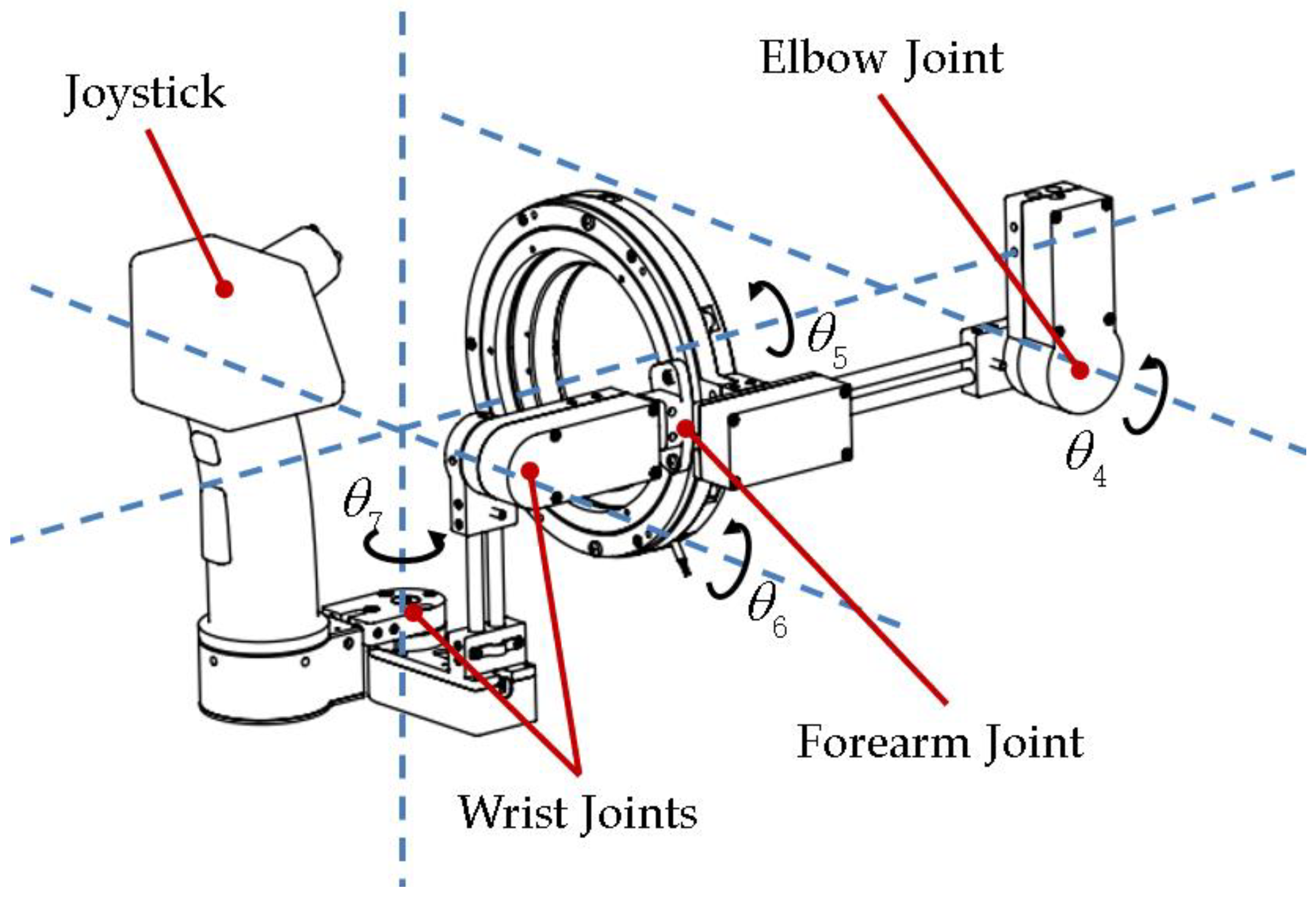
2.4. Position-Orientation Decoupled Wrist Mechanism

Humans have spherical wrist joints as depicted in Figure 2. When performing sophisticated manipulations such as surgery, such a structure can help people control the position and orientation of hands independently. Many anthropomorphic and industrial manipulators, like the KUKA LBR series [32] and Justin [33], are also designed to have the spherical 3-DOF wrist mechanism to achieve human-like dexterous behaviors. In teleoperation, it is necessary to decouple orientation from the position in the obtained end-effector pose, so that the operators’ intent could be intuitively presented on the slave manipulators.
The difficulties in the design of the wrist mechanism are similar to those of the shoulder mechanism. Especially for the forearm pronation/supination mechanism, the space of the rotational axis is occupied by the wearer’s forearm, so the bearings and encoder cannot be installed along the rotational axis. Existing works [34,35] proposed using the curved rigid rails to support the pronation/supination motion from outside of the forearm. The rotations are measured with IMU or encoder at the motor end. However, IMU sensors or indirect measurement of motion limit the precision of the entire system, while the use of curved rails makes the wrist mechanism bulky and hardly wearable.
In this research, we designed a compact 3-DOF wrist mechanism as depicted in Figure 12. To align with the pronation/supination rotational axis of the human arm and achieve compactness in the mechanism for measuring the forearm motion, we proposed using a thin-wall rolling bearing with an internal diameter of up to 90 mm to connect the forearm linkage and the wrist mechanism. A 19-bit absolute encoder with a hollow floating shaft (Netzer, DS-130, Misgav, Israel) is installed back to the bearing to measure the pronation/supination motion directly. The 2-DOF serial mechanism for measuring the flexion/extension and abduction/adduction motions of the wrist is installed on the inner ring of the forearm pronation/supination mechanism. The axes of the two DOFs are designed to converge with the forearm rotation axis at the same point, so that the wrist mechanism can work like the spherical joint. A versatile joystick is installed on the end of the wrist mechanism. The wearer’s hands can pass through the forearm rotation ring and hold the joystick. The joint angle values [ θ 4 , θ 5 , θ 6 , θ 7 ] can be read from the absolute encoders installed on the elbow, the forearm, and the wrist mechanism. The values can be directly mapped to the joint angle values [ q 4 , q 5 , q 6 , q 7 ] in the serial model in Section 2.1.

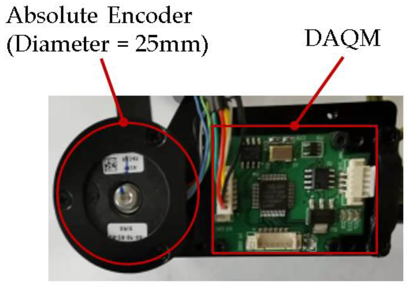
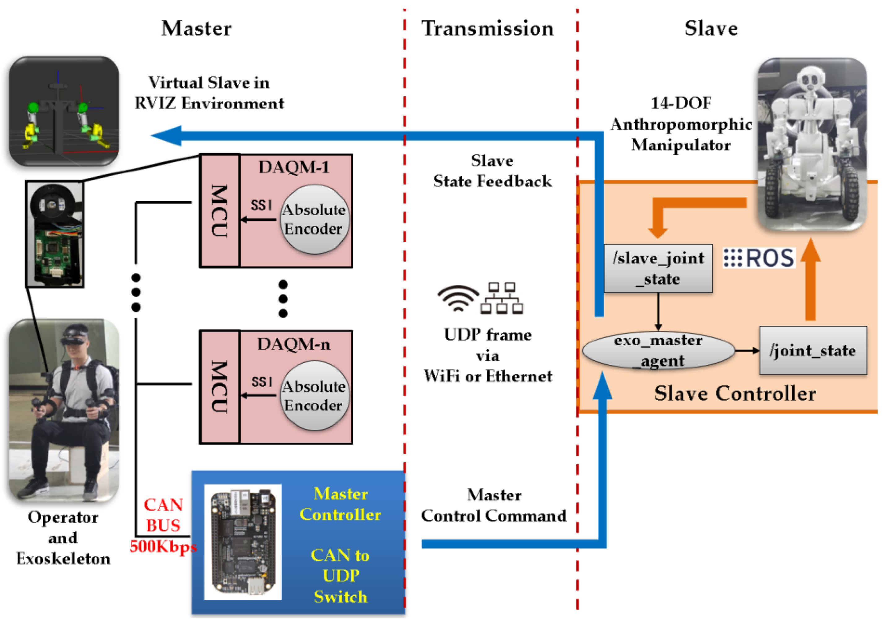
2.5. Data Acquisition and Transmission

We designed the exoskeleton as a distributed data acquisition system. To obtain an accurate estimation of the wearer’s upper limb pose, the joint angle values should be acquired and synchronously transmitted to the master controller. We developed a low-profile data acquisition module (DAQM) to read encoder data and transmit the values in real time. The DAQMs are installed near the absolute encoders of every joint. The DAQMs access the absolute encoders via the SSI interface and update the joint values at a 10 ms period. A DAQM connected with the absolute encoder is illustrated in Figure 13.
The DAQMs use STM32 as the MCU, which integrates the CAN controller. The DAQMs transmit the read joint data to the master controller via the CAN bus. The data acquisition network of the exoskeleton is composed of 17 nodes, including 14 DAQMs for encoders on the joints, 2 joystick controllers, and a master controller. It is important to plan the communication parameters, so that the data transmission can achieve good real-time performance and synchronicity. The DAQM nodes and the joystick controllers use a unified 4 bytes CAN frame protocol, which includes 3 bytes for saving the encoder data or joystick commands, and 1 byte for transmitting the status and diagnosis information. Encoders with 24-bit resolution or lower will all be supported. According to the data frame structure in CAN2.0A standard [36], the 4 byte frame contains several mandatory segments, including interframe space, SOF, arbitration ID, SRR, IDE, RTR, DLC, data field, CRC, ACK, and EOF. The summation of bit length for such a frame can reach 79. Additionally, some stuffed bits may be inserted to satisfy the CAN data link layer protocol. When transmitting, if the transmitter encounters a run of 5 successive ones or zeros it inserts a bit of the other polarity. The maximum length of the stuffed frame is estimated as below:
L m = 34 + 8 S m 5 + 48 + 8 S m
where S m is the byte length of the payload in the frame. When S m is 4, the maximum length of the frame will be 92 bits. Ideally, the CAN bus bandwidth used by node i is calculated as:
B i = F i L m b i t e r a t e
where F i is the sending frequency of node i, and bitrate is the baud rate of the CAN bus.
The CiA group suggests that an average busload of 50% should not be exceeded [37]. So, the limits should be taken into consideration when deciding the bit rate and frequency. The maximum length between two nodes in the exoskeleton is about 3 m. Therefore, we conservatively select 500 kbps as the CAN bus baud rate. The 16 nodes in the exoskeleton use identical 4 bytes CAN frame format. When 10 ms is used as the data upload period, every single node will occupy 1.84% of the full bandwidth of the CAN bus. The maximum overall busload for all 16 data transmission nodes is estimated at 29.44%.
We use a BeagleBone Black embedded computer, which is powered by an AM3358 cortex-A8 microprocessor, as the master controller. The BeagleBone Black has both a CAN bus and Ethernet interface on the board, which makes it perfect for working as a gateway between the local CAN network and the external Ethernet.
The software stack of the master controller is depicted in Figure 14. The BeagleBone Black runs UBUNTU 18.04LTS OS. We developed the gateway application for transferring data between the CAN interface and the Ethernet interface, which performs data exchange with two independent threads. The user space application obtains access to the CAN controller hardware through an open-source library libsocketcan [38], which provides socket-style API.

2.6. Implementation Details of a Prototype

The shoulder joint, elbow joint, and wrist joint are connected with two parallel carbon fiber tubes. To make the exoskeleton flexible to the variant physical size of the wearer, we designed the adjustable linkage mounting holes (Figure 15) on the connection parts. The length of the upper arm, forearm, and palm can be adjusted individually by taking advantage of this mechanism. The total length of the upper limb exoskeleton is adjustable from 460 mm to 540 mm. Empirically, with such an adjustment range, the exoskeleton device can accommodate wearers from 160 cm to 185 cm.
We built a back frame as the installation base of the two exoskeleton arms. The shape of the back frame was designed to conform to the curve of the back of the human body. A soft nylon fabric carrying system was sewn onto the front side of the back frame. With the help of the back frame and the carrying system, the load of the whole system can be transferred and distributed evenly among the shoulder, back, and waist, so that the wearer will not feel uncomfortable when wearing the system for a long time. Additionally, the carrying system helps with fixing the back frame to the torso tightly and steadily, which guarantees that the RCM of the shoulder mechanism properly aligns with the rotational center of the GH joint.
The power supply and electrical systems, including the battery pack, DC/DC converter, and slave controller board, were installed behind the back frame and are protected by a plastic shield, as illustrated in Figure 16. We used a 24 V, 5700 mAh battery pack (TB48S, DJI, Shenzhen, China) as the power source of the system, which can support the system to run continuously over 36 h. A step-down DC/DC converter (URA2405LD-30WR3, MORNSON, Guangzhou, China) converts the 24 V power from the battery to 5 V for supplying the slave controller and the DAQMs.
The back frame and the joint parts were mainly manufactured with high-strength aluminum alloy A7075P. The upper arm linkage, forearm linkage, and wrist linkage were made of 5 mm carbon fiber tubes, which are lightweight and high stiffness.
The overall mass (including the battery) of the prototype is 4.8 kg. The mass of the moving part on a single arm is 1.1 kg, and 0.76 kg of the mass is distributed on the forearm mechanism. However, part of the load will be borne by the back frame and transferred to the torso when properly wearing the exoskeleton.

3. Motion Mapping to the Anthropomorphic Manipulators

In this section, we use a human scale 14-DOF dual arm anthropomorphic manipulator to present the teleoperation control method with the proposed upper limb exoskeleton.
As depicted in Figure 17, the arm of the 14-DOF manipulator has a similar kinematic structure to the human upper limb model described in Section 2.1. So, directly mapping the joint space positions obtained from the exoskeleton to the slave manipulator is a very straightforward approach in the isomorphic master-slave context. In addition, task space mapping could be a more general method for teleoperation control of the manipulators with different kinematic structures. We describe the two types of mapping strategies in this section.

3.1. Joint Space Mapping

As described in Section 2.3 and Section 2.4, the upper limb pose can be estimated with the joint position data obtained from the exoskeleton master. We can use the resolved 7-dimensional joint position vector q m a s t e r to recover the wearer’s upper limb pose on the 7-DOF kinematic model in Figure 2. Every single arm of the slave robot is driven by the 7-dimensional control command vector q s l a v e . We use the following mapping to convert q m a s t e r to q s l a v e for implementing the joint space teleoperation control:
q s l a v e = M t r a n s q m a s t e r + q o f f s e t
where M t r a n s is a transformation matrix which is used to adjust the joint space mapping sequence and scale between the master and the slave. The vector q o f f s e t is used to reflect the initial state difference between the master and the slave.
The joint space mapping strategy is simple and intuitive for the operator. The movement on the operator’s specific joint will instantly drive the counterpart of the slave robot. The joint space mapping method is also proper for time-sensitive situations because no inverse kinematic calculation is required. However, small differences in kinematic parameters may exist between the master and slave, which could lead to considerable absolute error in the position control of the end-effector.

3.2. Task Space Mapping

If high precision control of the end-effector is demanded, or the DOF and kinematic structure of the slave manipulator is significantly different from the 7-DOF upper limb model, task space mapping control will be essential in teleoperation.
The task space mapping control method takes a 6-DOF end-effector target pose, which is provided by the operator’s hand pose, and performs inverse kinematics (IK) to convert the task space target into joint space commands. However, in the teleoperation control of the anthropomorphic manipulators, not only the end-effector tracking should be cared about, but also imposing the human posture into the slave manipulator is preferred. Most anthropomorphic manipulators, including the one depicted in Figure 17, have redundant kinematic structures, which means the ability to adjust their posture in the null space of the end-effector. The exoskeleton master device, which can capture the posture of the entire upper limb, enables the posture mimicry features on such redundant manipulators in teleoperation. However, if a kinematic discrepancy exists between the master and slave, it could be impossible to meet simultaneously both the end-effector tracking and the posture mimicry requirements in teleoperation control. To address this dilemma, we proposed a hierarchical scheme to coordinate the target pose-tracking task of the end-effector and the posture control task. To this end, we developed the control scheme (Figure 18) based on the CLIK algorithm [39] and additionally designed a posture mimicry controller.
The hierarchical CLIK scheme generates velocity control commands q ˙ for the slave joints as follows:
q ˙ = J ( q ) ( x ˙ d + K p ( x d x ) ) + ( I J ( q ) J ( q ) ) q ˙ 0
where J ( q ) is the Moore–Penrose inverse of J ( q ) . The 6-DOF vector x d provides the desired end-effector target pose, which can be obtained from the master status and forward kinematics. The 6-DOF vector x is the current pose of the slave end-effector. The positive definite matrix K p guarantees the convergence of q ˙ . The matrix ( I J ( q ) J ( q ) ) projects any joint space velocity q ˙ 0 onto the null space of the slave end-effector [39].
The two items on the right side of Equation (12) act on two different tasks: the first item keeps the slave end-effector tracking the target pose, which is treated as the prior task; the second item only adjusts the slave posture in null space, which is treated as the secondary task.
In this research, the secondary task aims at making the slave manipulator mimic the operator’s posture. We achieve this by performing alignment of the upper arm orientation between the master and the slave. An objective function is established to reflect the orientation error between the master and the slave as follows:
H ( q ) = δ x 2 + δ y 2 + δ z 2
where the vector δ Θ = ( δ x , δ y , δ z ) T is the angular difference between two rotation matrices, whose components are available from the rotation differential matrix below:
S ( δ Θ ) = 0 δ z δ y δ z 0 δ x δ y δ x 0
For the two rotation matrices R m 0 3 and R s 0 3 representing the upper arm orientation of the master and the slave respectively, their angular differential can be derived by [40]:
S ( δ Θ ) = R m 0 3 R s 0 3 T I 3 × 3
Then we define q ˙ 0 as a negative proportion of the gradient of the objective function H ( q ) as follows:
q ˙ 0 = η H ( q ) H ( q ) = H ( q ) q T
where η is a positive scalar, and the gradient vector H ( q ) can minimize the posture error as soon as possible.

4. Experiments

4.1. Experimental Setup

Figure 19 illustrates the experimental setup for evaluating the proposed exoskeleton and the teleoperation control methods.
The exoskeleton master is connected to the slave robot via Ethernet and sends master control commands as UDP packages every 10 ms. The controller of the slave robot is based on ROS. An ROS node “/exo_master_agent” receives the UDP command packages and maps the master commands to joint space commands for the slave robot and publishes them to the ROS topic “/joint_state” to control the robot. The “/exo_master_agent” also subscribes the topic “/slave_joint_state”, which reflects the real-time state of all the slave joints and sends them to the master side for monitoring. A virtual slave robot can be observed on the master side through RVIZ, which is a 3D visualization tool for ROS.
Both of the models for the master and the slave are described by URDF files in ROS. The states of the interested frames in the URDF files can be tracked and recorded with TF in ROS.
The subject for evaluating the range of motion is male, 178 cm, 74 kg. The DH parameters for the exoskeleton master and the slave robot are listed in Table 2.

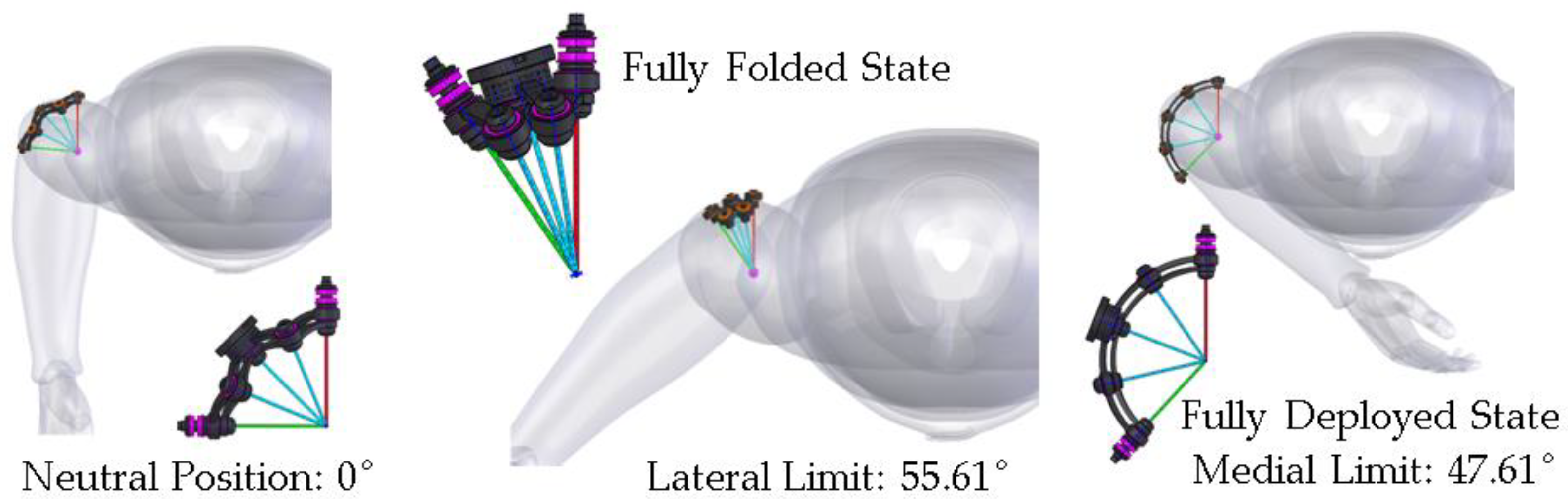
4.2. Range of Motion Evaluation

To assess how much the range of motion will be limited by wearing the proposed exoskeleton, the wearer was instructed to perform the seven motions depicted in Figure 2 and try to achieve the maximum range. We took three photos for each motion to record the positive limit, negative limit, and neutral positions. Then the range of motion was measured on the pictures with ImageJ [41]. We also recorded the data for the same subject without wearing the exoskeleton to evaluate the active coverage of the range of motion. Examples of the measurements for shoulder flexion/extension are illustrated in Figure 20. The measurement results are listed in Table 3. It should be noted that this method only provides a preliminary evaluation of the range of motions. So, we use an integer percentage to present coverage of the range of motion.

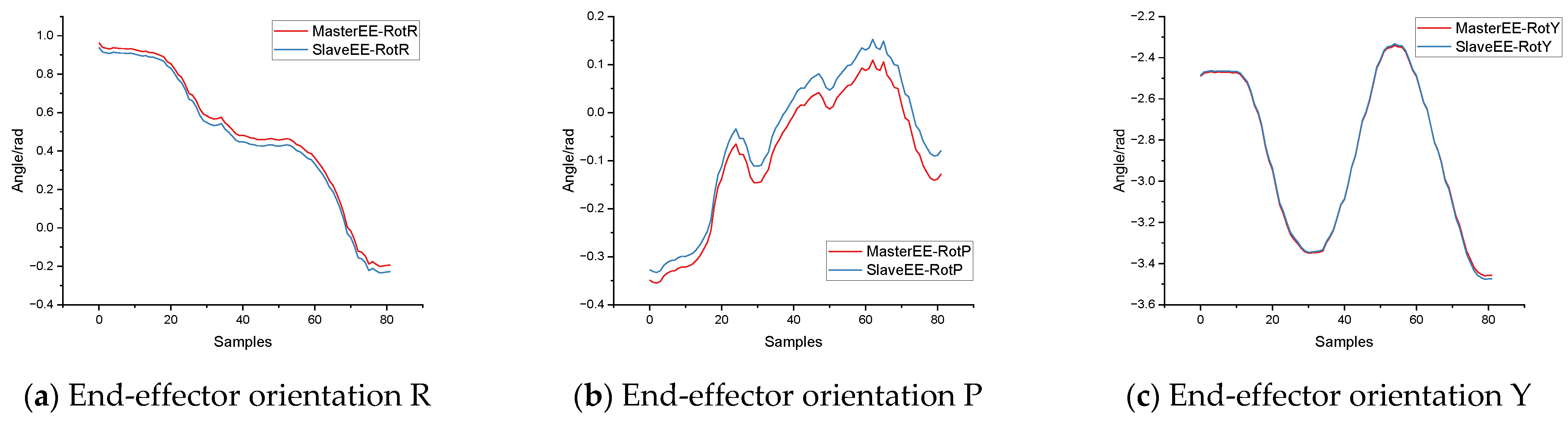
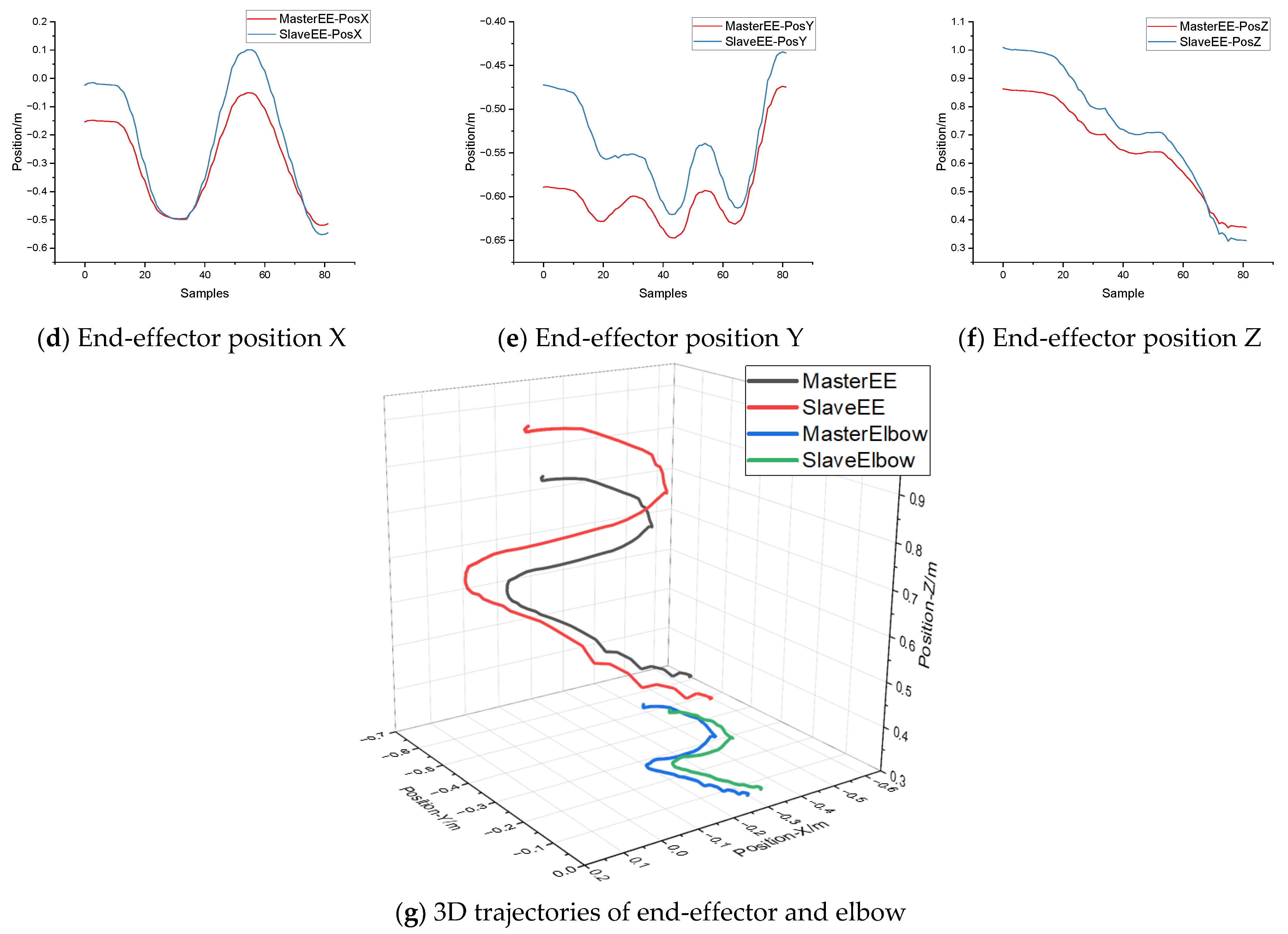
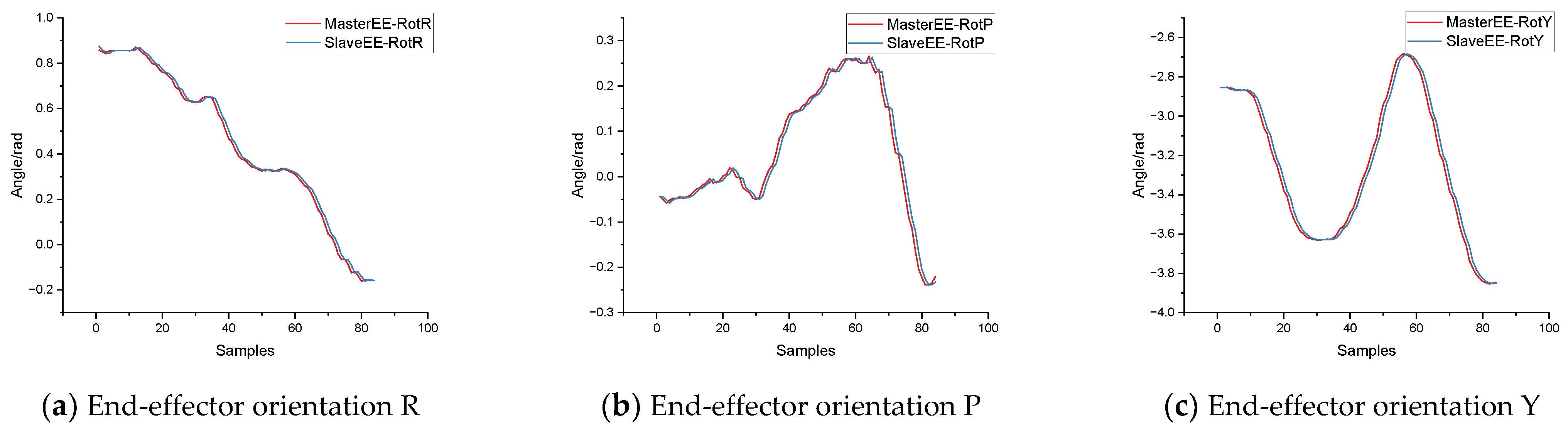
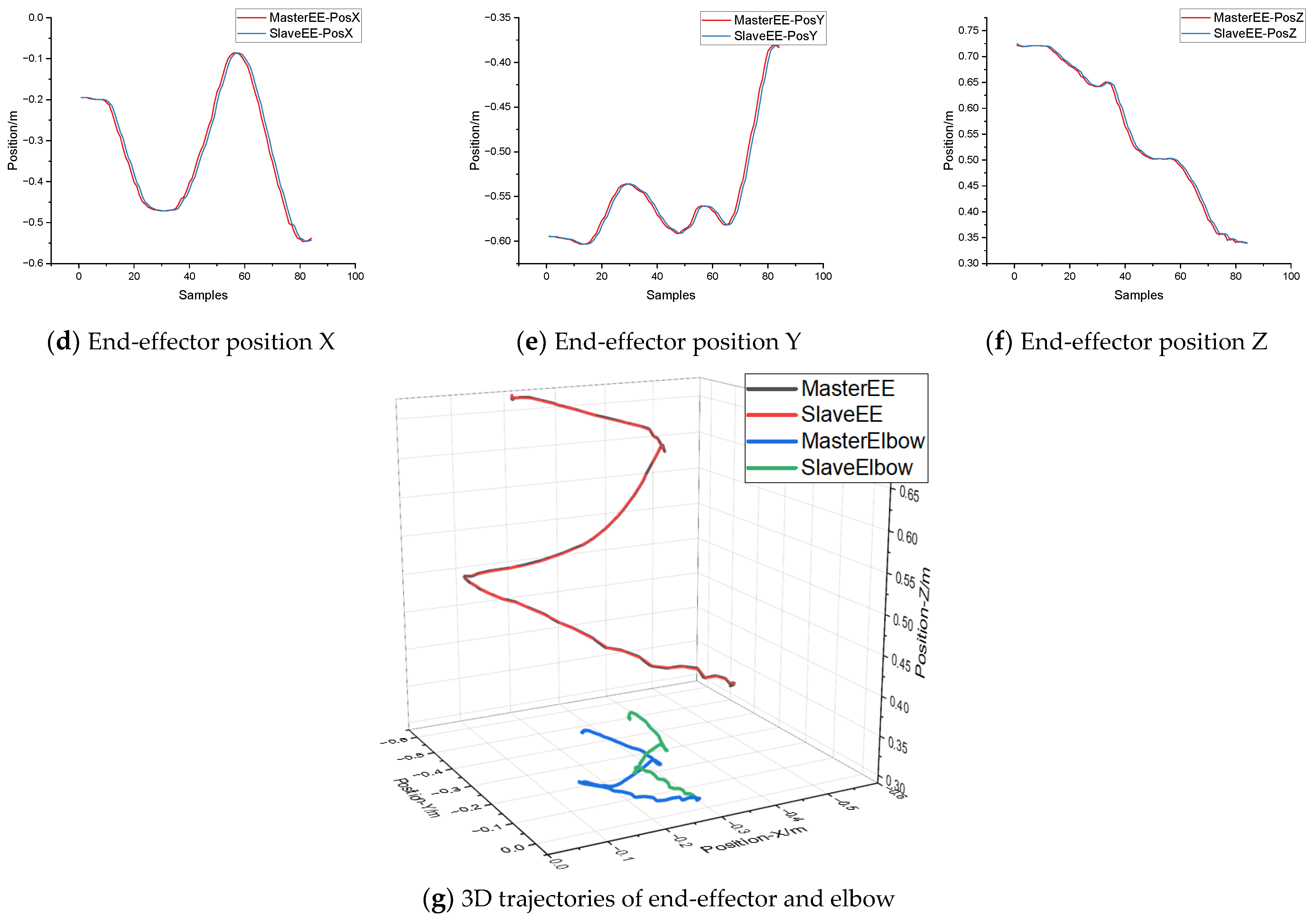
4.3. Precision and Dynamic Performance Evaluation

We performed teleoperation in a simulation environment to check if the proposed mapping control methods work well. The joint space and task space mapping strategies were tested individually. In each experiment, the operator was instructed to control the virtual manipulator to draw specific trajectories covering most areas of the working space. The 6-DOF human hand pose and the slave end-effector pose were recorded to evaluate the precision and dynamic performance of target tracking. We also recorded the elbow trajectories of both sides to evaluate the posture similarity between master and slave in teleoperation. The following error results of simulated teleoperation experiments with the joint space control strategy and task space control strategy were illustrated in Figure 21 and Figure 22 respectively.

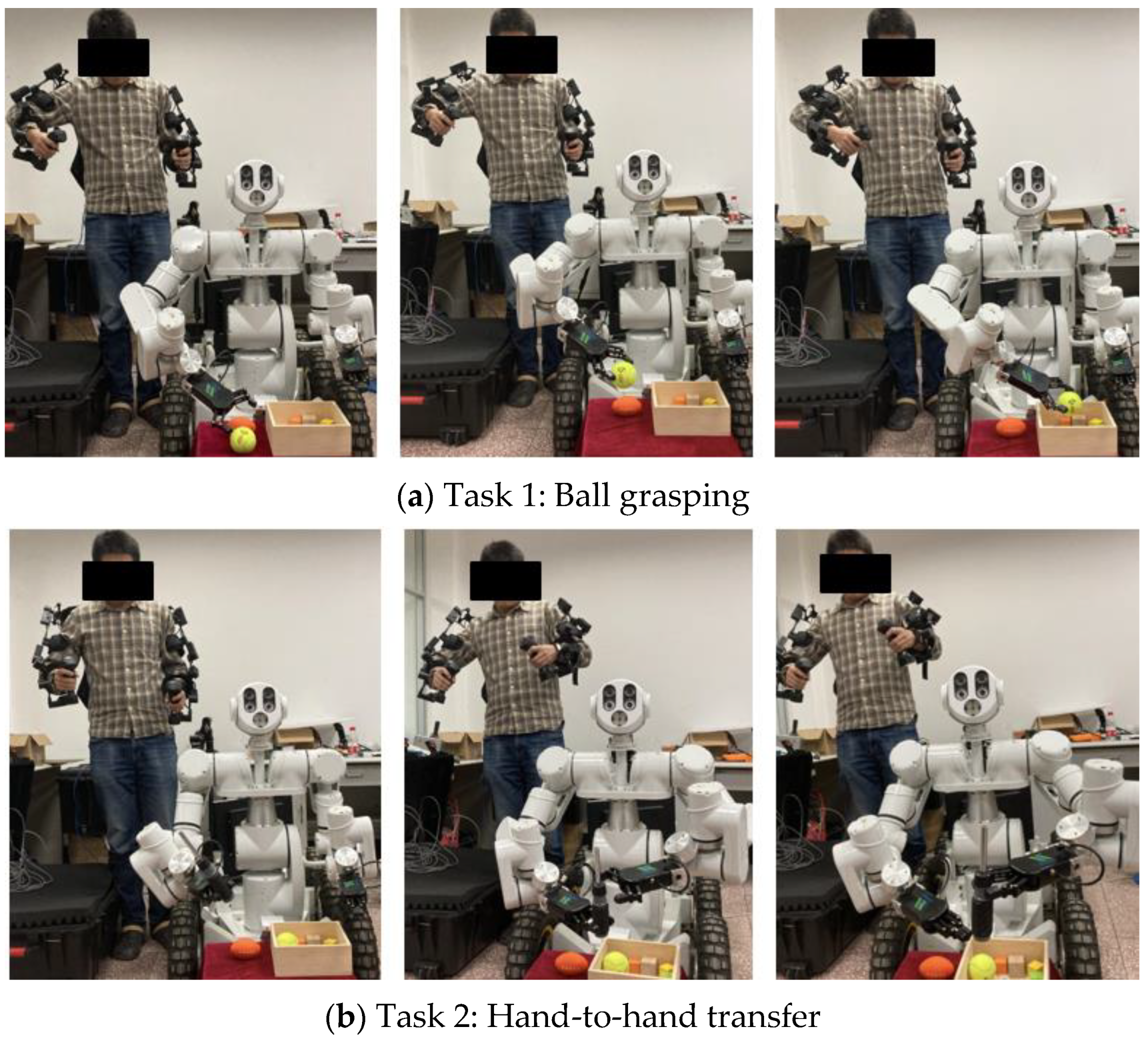
4.4. Task Demonstrations on a Real Anthropomorphic Manipulator

We performed two teleoperation tasks to demonstrate the intuitiveness of the proposed exoskeleton device and the mapping control methods. The experiments are illustrated in Figure 23.
In task 1, the operator controlled the slave robot to grasp a tennis ball and put it into a box. In task 2, the operator controlled the slave robot to transfer a screwdriver from one hand to the other.
The task was executed with both task space control and joint space control 10 times. The success rates are listed in Table 4.

5. Discussion

From the results listed in Table 3, we found that the most severe cases of limited mobility occurred in the shoulder abduction motion. When wearing the exoskeleton, only 61% of the normal range of motion in this direction could be reached. Because the back frame has a curved outline to fit the shape of the wearer’s torso, the shoulder mechanism will collide with the back frame when the wearer lifts his arms in the abduction direction to about 85°. Fortunately, the worst case will only happen when the wearer lifts his arms in the frontal plane, If the wearer’s arms are slightly (more than 10°) ahead of the frontal plane, the lifting motion will not be limited at all. So, in most practical situations, arm-lifting activities are not limited by the exoskeleton. Similarly, the subject was required to keep the elbow close to his torso when measuring the range of motion in the shoulder medial/lateral direction. Consequently, the coverage result of shoulder medial direction was reported as 76%. However, if the wearer is allowed to move his elbow slightly, the limitation will be eliminated. In 10 of the 14 basic upper limb motions, the exoskeleton covered more than 95% of the normal range of motion.
When the joint space control strategy was applied, the end-effector tracking errors between the master and slave of the 6D Cartesian space are illustrated in (a–f) of Figure 21. We found significant tracking errors in the positional dimensions, while the errors vary with position. This is caused by the difference in kinematic parameters (Table 2) between master and slave. Especially for the Y dimension, the maximum error between the master and slave can reach 0.12 m in the test trajectory. Because the gripper of the slave manipulator is much longer than the human hand along the Y axis, the position of the slave end-effector frame will be 0.15 m ahead of that of the master in the initial state. As a result, the position control will be biased by the absolute mechanical difference when moving along the Y axis. This error will be diminished as the end-effector gets close to the frontal plane. This reason also applies to the other two axes. However, the upper limb posture is defined by the relative position of the shoulder, elbow, and wrist. The prerequisite for applying joint space control strategy is similar kinematic structure and arm length ratio (upper arm: forearm) between the manipulator and the human arm. We suppose that the prerequisites could ensure a similar appearance between the master and slave when applying joint space mapping. In our experimental setup, the arm length ratio is 1:1.02 on the master side and 1:1.03 on the slave side. So, from the 3D trajectories depicted in (g) of Figure 21, we found that, although absolute differences always existed between the master and the slave, both the trajectories of the slave end-effector and elbow could maintain good similarity with the master.
When the task space control strategy was applied, as illustrated in (a–f) of Figure 22, the slave end-effector maintains good tracking performance in all dimensions. The average pose errors between the master and the slave are 7 mm in position and 0.019 rad in orientation for the testing trajectory. In the 3D trajectory depicted in (g) of Figure 22, the end-effector of the master and the slave always kept close to each other. However, the elbow trajectories show an obvious difference, which means the posture of the slave may be a little different from the operator. As described in Section 3.2, in a hierarchical CLIK control framework, the end-effector tracking task is treated as the main task, while the posture mimicry task is treated as the secondary task. As the overall length of the kinematic chains of the master and slave are 0.535 m and 0.705 m respectively, the posture mimicry task must make way for the precision of end-effector tracking.
In the practical task demonstrations with our exoskeleton master, both the above control strategies were tested. For task 1, the ball picking task, the key factor for success is delicate regulation of the position and orientation of the 2-finger robotic hand, so that it can reach a proper gripping point. Because a position–orientation decoupled wrist mechanism is applied in the exoskeleton, the operator will feel more intuitive to perform such an operation with joint space control. In task 2, the key factor for successfully transferring objects from one hand to another is the perception of the relative position and movements of the two hands. So, with task space control, the operator could feel better control of the position of the end-effector.

6. Conclusions

In this paper, we presented the development of an upper limb exoskeleton for intuitive teleoperation of anthropomorphic manipulators. We designed the exoskeleton human-machine interface as a 14-DOF, lightweight, and passive wearable device, which is only 4.8 kg in total. With the help of a curved back frame and carrying system, the exoskeleton can be steadily fixed on the torso, providing a self-alignment feature for improving measurement accuracy. A compact spherical scissor mechanism was proposed as the shoulder mechanism to mitigate the limitation of the range of motion when wearing the exoskeleton.
A comparison evaluation showed that when wearing the proposed exoskeleton, the wearer can reach most areas of the normal range of motion. In 10 of the 14 basic upper limb motions, the exoskeleton covered more than 95% of the normal range of motion. Therefore, as a human-machine interface, the exoskeleton will not make the user feel natural or uncomfortable in teleoperation. Both the joint space and task space control strategies were devised and tested on a 14-DOF dual-arm anthropomorphic manipulator. Demonstration tasks were also performed to show the different features of the two control methods. The joint space control strategy provides a simple and intuitive mapping between the master and slave. It could be particularly effective in situations where individual control of some joints is required. However, in the case where accurate control of the end-effector is desired, or the kinematic structure is significantly different between the master and slave, the task space control strategy will be essential. A simulation experiment showed that, although the 14-DOF slave manipulator was different in some mechanical parameters from the master, good tracking accuracy (7 mm position error and 0.019 rad orientation error on average) could be achieved as well as maintaining human-like posture on the slave side with the task space control strategy. The task space control method makes the proposed exoskeleton a general-purpose master device for the teleoperation of different types of anthropomorphic manipulators.
Our future work will use the exoskeleton as an intuitive human-machine interface to teach robot manipulation skills with imitation learning. The trained autonomous control system could assist the teleoperation in a shared autonomy paradigm.

Author Contributions

Conceptualization, L.Z. and P.Y.; methodology, L.Z. and T.Y.; software, L.Z.; validation, Y.Y. and T.Y.; formal analysis, T.Y.; investigation, L.Z.; resources, Y.Y.; data curation, L.Z.; writing—original draft preparation, L.Z.; writing—review and editing, P.Y.; visualization, T.Y.; supervision, P.Y.; project administration, P.Y.; funding acquisition, P.Y. All authors have read and agreed to the published version of the manuscript.

Funding

This work was supported by National Key R&D Program of China (Grant Nos. 2016YFE0206200), the National Natural Science of China (Grant Nos. 61821005, 91748212).

Institutional Review Board Statement

The experimental protocol was approved by the Shenyang Institute of Automation’s Research Ethics Committee (approval number: 2022-018), and all procedures were conducted in accordance with the approved study protocol.

Data Availability Statement

Not applicable.

Conflicts of Interest

The authors declare no conflict of interest.

References

  1. Caiza, G.; Garcia, C.A.; Naranjo, J.E.; Garcia, M.V. Flexible Robotic Teleoperation Architecture for Intelligent Oil Fields. Heliyon 2020, 6, e03833. [Google Scholar] [CrossRef] [PubMed]
  2. Conte, D.; Leamy, S.; Furukawa, T. Design and Map-Based Teleoperation of a Robot for Disinfection of COVID-19 in Complex Indoor Environments. In Proceedings of the 2020 IEEE International Symposium on Safety, Security, and Rescue Robotics (SSRR), Abu Dhabi, United Arab Emirates, 4–6 November 2020; pp. 276–282. [Google Scholar]
  3. Guo, J.; Ye, L.; Liu, H.; Wang, X.; Liang, L.; Liang, B. Safety-Oriented Teleoperation of a Dual-Arm Mobile Manipulation Robot. In Intelligent Robotics and Applications, Proceedings of the 15th International Conference, ICIRA 2022, Harbin, China, 1–3 August 2022; Liu, H., Yin, Z., Liu, L., Jiang, L., Gu, G., Wu, X., Ren, W., Eds.; Springer International Publishing: Cham, Switzerland, 2022; pp. 780–792. [Google Scholar]
  4. Liu, G.; Geng, X.; Liu, L.; Wang, Y. Haptic Based Teleoperation with Master-Slave Motion Mapping and Haptic Rendering for Space Exploration. Chin. J. Aeronaut. 2019, 32, 723–736. [Google Scholar] [CrossRef]
  5. Nawab, A.; Chintamani, K.; Ellis, D.; Auner, G.; Pandya, A. Joystick Mapped Augmented Reality Cues for End-Effector Controlled Tele-Operated Robots. In Proceedings of the 2007 IEEE Virtual Reality Conference, Charlotte, NC, USA, 10–14 March 2007; pp. 263–266. [Google Scholar]
  6. Cornejo, J.; Denegri, E.; Vasquez, K.; Ramos, O.E. Real-Time Joystick Teleoperation of the Sawyer Robot Using a Numerical Approach. In Proceedings of the 2018 IEEE ANDESCON, Cali, Colombia, 22–24 August 2018; pp. 1–3. [Google Scholar]
  7. Silva, A.J.; Ramirez, O.A.D.; Vega, V.P.; Oliver, J.P.O. PHANToM OMNI Haptic Device: Kinematic and Manipulability. In Proceedings of the 2009 Electronics, Robotics and Automotive Mechanics Conference (CERMA), Cuernavaca, Mexico, 22–25 September 2009; pp. 193–198. [Google Scholar]
  8. Tobergte, A.; Helmer, P.; Hagn, U.; Rouiller, P.; Thielmann, S.; Grange, S.; Albu-Schäffer, A.; Conti, F.; Hirzinger, G. The Sigma.7 Haptic Interface for MiroSurge: A New Bi-Manual Surgical Console. In Proceedings of the 2011 IEEE/RSJ International Conference on Intelligent Robots and Systems, San Francisco, CA, USA, 25–30 September 2011; pp. 3023–3030. [Google Scholar]
  9. Núñez, M.L.; Dajles, D.; Siles, F. Teleoperation of a Humanoid Robot Using an Optical Motion Capture System. In Proceedings of the 2018 IEEE International Work Conference on Bioinspired Intelligence (IWOBI), San Carlos, Costa Rica, 18–20 July 2018; pp. 1–8. [Google Scholar]
  10. Vongchumyen, C.; Bamrung, C.; Kamintra, W.; Watcharapupong, A. Teleoperation of Humanoid Robot by Motion Capturing Using KINECT. In Proceedings of the 2018 International Conference on Engineering, Applied Sciences, and Technology (ICEAST), Phuket, Thailand, 4–7 July 2018; pp. 1–4. [Google Scholar]
  11. Vasiljevic, G.; Jagodin, N.; Kovacic, Z. Kinect-Based Robot Teleoperation by Velocities Control in the Joint/Cartesian Frames. IFAC Proc. Vol. 2012, 45, 805–810. [Google Scholar] [CrossRef]
  12. Miller, N.; Jenkins, O.C.; Kallmann, M.; Mataric, M.J. Motion Capture from Inertial Sensing for Untethered Humanoid Teleoperation. In Proceedings of the 4th IEEE/RAS International Conference on Humanoid Robots, Santa Monica, CA, USA, 28–30 November 2004; Volume 2, pp. 547–565. [Google Scholar]
  13. Park, S.; Jung, Y.; Bae, J. An Interactive and Intuitive Control Interface for a Tele-Operated Robot (AVATAR) System. Mechatronics 2018, 55, 54–62. [Google Scholar] [CrossRef]
  14. Proietti, T.; Crocher, V.; Roby-Brami, A.; Jarrassé, N. Upper-Limb Robotic Exoskeletons for Neurorehabilitation: A Review on Control Strategies. IEEE Rev. Biomed. Eng. 2016, 9, 4–14. [Google Scholar] [CrossRef] [PubMed] [Green Version]
  15. Esposito, D.; Centracchio, J.; Andreozzi, E.; Savino, S.; Gargiulo, G.D.; Naik, G.R.; Bifulco, P. Design of a 3D-Printed Hand Exoskeleton Based on Force-Myography Control for Assistance and Rehabilitation. Machines 2022, 10, 57. [Google Scholar] [CrossRef]
  16. Zuccon, G.; Bottin, M.; Ceccarelli, M.; Rosati, G. Design and Performance of an Elbow Assisting Mechanism. Machines 2020, 8, 68. [Google Scholar] [CrossRef]
  17. Geonea, I.; Copilusi, C.; Dumitru, N.; Margine, A.; Ciurezu, L.; Rosca, A.S. A New Exoskeleton Robot for Human Motion Assistance. In Proceedings of the 2022 IEEE International Conference on Automation, Quality and Testing, Robotics (AQTR), Cluj-Napoca, Romania, 19–21 May 2022; pp. 1–6. [Google Scholar]
  18. Bai, S.; Islam, M.R.; Hansen, K.; Nørgaard, J.; Chen, C.-Y.; Yang, G. A Semi-Active Upper-Body Exoskeleton for Motion Assistance. In Wearable Robotics: Challenges and Trends, Proceedings of the 5th International Symposium on Wearable Robotics, WeRob2020, and of WearRAcon Europe 2020, 13–16 October 2020; Moreno, J.C., Masood, J., Schneider, U., Maufroy, C., Pons, J.L., Eds.; Springer International Publishing: Cham, Switzerland, 2022; pp. 301–305. [Google Scholar]
  19. Planthaber, S.; Mallwitz, M.; Kirchner, E.A. Immersive Robot Control in Virtual Reality to Command Robots in Space Missions. JSEA 2018, 11, 341–347. [Google Scholar] [CrossRef] [Green Version]
  20. Maekawa, A.; Takahashi, S.; Saraiji, M.Y.; Wakisaka, S.; Iwata, H.; Inami, M. Naviarm: Augmenting the Learning of Motor Skills Using a Backpack-Type Robotic Arm System. In Proceedings of the 10th Augmented Human International Conference 2019, Reims, France, 11–12 March 2019; Association for Computing Machinery: New York, NY, USA, 2019; pp. 1–8. [Google Scholar]
  21. Barnaby, G.; Roudaut, A. Mantis: A Scalable, Lightweight and Accessible Architecture to Build Multiform Force Feedback Systems. In Proceedings of the 32nd Annual ACM Symposium on User Interface Software and Technology, New Orleans, LA, USA, 20–23 October 2019; Association for Computing Machinery: New York, NY, USA, 2019; pp. 937–948. [Google Scholar]
  22. Lee, C.-H.; Choi, J.; Lee, H.; Kim, J.; Lee, K.; Bang, Y. Exoskeletal Master Device for Dual Arm Robot Teaching. Mechatronics 2017, 43, 76–85. [Google Scholar] [CrossRef]
  23. Holzbaur, K.R.S.; Murray, W.M.; Delp, S.L. A Model of the Upper Extremity for Simulating Musculoskeletal Surgery and Analyzing Neuromuscular Control. Ann. Biomed. Eng. 2005, 33, 829–840. [Google Scholar] [CrossRef] [PubMed]
  24. Roderick, S.; Liszka, M.; Carignan, C.; Roderick, S.; Liszka, M.; Carignan, C. Design of an Arm Exoskeleton with Scapula Motion for Shoulder Rehabilitation. In Proceedings of the ICAR ’05, 12th International Conference on Advanced Robotics, Seattle, WA, USA, 18–20 July 2005; pp. 524–531. [Google Scholar]
  25. Clinicalgate.com Upper Limb—General Description. Available online: https://clinicalgate.com/upper-limb-2/ (accessed on 1 March 2023).
  26. Boone, D.C.; Azen, S.P. Normal Range of Motion of Joints in Male Subjects. J. Bone Jt. Surg. Am. 1979, 61, 756–759. [Google Scholar] [CrossRef]
  27. Lo, H.S.; Xie, S.S.Q. Optimization of a Redundant 4R Robot for a Shoulder Exoskeleton. In Proceedings of the 2013 IEEE/ASME International Conference on Advanced Intelligent Mechatronics, Wollongong, Australia, 9–12 July 2013; pp. 798–803. [Google Scholar]
  28. Castro, M.N.; Rasmussen, J.; Andersen, M.S.; Bai, S. A Compact 3-DOF Shoulder Mechanism Constructed with Scissors Linkages for Exoskeleton Applications. Mech. Mach. Theory 2019, 132, 264–278. [Google Scholar] [CrossRef]
  29. Li, R.; Liu, Z.; Mi, W.; Bai, S.; Zhang, J. Design and Kinematic Analysis of a Novel Wire-Driven Spherical Scissors Mechanism. In Recent Advances in Mechanisms, Transmissions and Applications; Wang, D., Petuya, V., Chen, Y., Yu, S., Eds.; Springer: Singapore, 2020; pp. 192–200. [Google Scholar]
  30. Balser, F.; Desai, R.; Ekizoglou, A.; Bai, S. A Novel Passive Shoulder Exoskeleton Designed with Variable Stiffness Mechanism. IEEE Robot. Autom. Lett. 2022, 7, 2748–2754. [Google Scholar] [CrossRef]
  31. Matsui, K.; Tachibana, T.; Nobuhara, K.; Uchiyama, Y. Translational Movement within the Glenohumeral Joint at Different Rotation Velocities as Seen by Cine MRI. J. Exp. Orthop. 2018, 5, 7. [Google Scholar] [CrossRef] [PubMed] [Green Version]
  32. Bischoff, R.; Kurth, J.; Schreiber, G.; Koeppe, R.; Albu-Schaeffer, A.; Beyer, A.; Eiberger, O.; Haddadin, S.; Stemmer, A.; Grunwald, G.; et al. The KUKA-DLR Lightweight Robot Arm—A New Reference Platform for Robotics Research and Manufacturing. In Proceedings of the ISR 2010 (41st International Symposium on Robotics) and ROBOTIK 2010 (6th German Conference on Robotics), Munich, Germany, 7–9 June 2010; pp. 1–8. [Google Scholar]
  33. Bäuml, B.; Hammer, T.; Wagner, R.; Birbach, O.; Gumpert, T.; Zhi, F.; Hillenbrand, U.; Beer, S.; Friedl, W.; Butterfass, J. Agile Justin: An Upgraded Member of DLR’s Family of Lightweight and Torque Controlled Humanoids. In Proceedings of the 2014 IEEE International Conference on Robotics and Automation (ICRA), Hong Kong, China, 31 May–7 June 2014; pp. 2562–2563. [Google Scholar]
  34. Perry, J.C.; Trimble, S.; Machado, L.G.C.; Schroeder, J.S.; Belloso, A.; Rodriguez-de-Pablo, C.; Keller, T. Design of a Spring-Assisted Exoskeleton Module for Wrist and Hand Rehabilitation. In Proceedings of the 2016 38th Annual International Conference of the IEEE Engineering in Medicine and Biology Society (EMBC), Orlando, FL, USA, 16–20 August 2016; pp. 594–597. [Google Scholar]
  35. Perry, J.C.; Rosen, J.; Burns, S. Upper-Limb Powered Exoskeleton Design. IEEE/ASME Trans. Mechatron. 2007, 12, 408–417. [Google Scholar] [CrossRef]
  36. Di Natale, M.; Zeng, H.; Giusto, P.; Ghosal, A. Understanding and Using the Controller Area Network Communication Protocol: Theory and Practice; Springer: New York, NY, USA, 2012; ISBN 978-1-4614-0313-5. [Google Scholar]
  37. CAN in Automation Designing a CAN Network. Available online: https://www.can-cia.org/can-knowledge/can/design-can-network/ (accessed on 27 February 2023).
  38. Kleine-Budde, M. SocketCAN—The Official CAN API of the Linux Kernel; Hambach Castle: Neustadt, Germany, 2012; Volume 5, pp. 17–22. [Google Scholar]
  39. Wang, J.; Li, Y.; Zhao, X. Inverse Kinematics and Control of a 7-DOF Redundant Manipulator Based on the Closed-Loop Algorithm. Int. J. Adv. Robot. Syst. 2010, 7, 37. [Google Scholar] [CrossRef]
  40. Corke, P. Robotics, Vision and Control; Springer: Berlin/Heidelberg, Germany, 2011. [Google Scholar]
  41. Rueden, C.T.; Schindelin, J.; Hiner, M.C.; DeZonia, B.E.; Walter, A.E.; Arena, E.T.; Eliceiri, K.W. ImageJ2: ImageJ for the next Generation of Scientific Image Data. BMC Bioinform. 2017, 18, 529. [Google Scholar] [CrossRef] [PubMed] [Green Version]
Figure 1. The wearable upper limb exoskeleton system.
Machines 11 00441 g001
Figure 2. The basic motions (left) of the upper limb and its equivalent serial model (right). The figures of basic motions are adapted from [25].
Machines 11 00441 g002
Figure 3. The CAD model of the spherical scissor mechanism.
Machines 11 00441 g003
Figure 4. Maximum deployed status of the spherical scissor mechanism.
Machines 11 00441 g004
Figure 5. Maximum folded status of the spherical scissor mechanism.
Machines 11 00441 g005
Figure 6. Wearing demonstration of the neutral, lateral limit, and medial limit state of the prototype development.
Machines 11 00441 g006
Figure 7. Coordinate system of the base frame and the upper arm frame in the initial state.
Machines 11 00441 g007
Figure 8. Frame rotation with the shoulder abduction/adduction motion.
Machines 11 00441 g008
Figure 9. Frame rotation with the shoulder medial/lateral motion.
Machines 11 00441 g009
Figure 10. Frame rotation with the flexion/extension motion.
Machines 11 00441 g010
Figure 11. The mechanical structure of the spherical scissor exoskeleton shoulder.
Machines 11 00441 g011
Figure 12. The mechanical structure of the exoskeleton elbow and wrist.
Machines 11 00441 g012
Figure 13. Absolute encoder and the developed DAQM.
Machines 11 00441 g013
Figure 14. Software stack of the master controller.
Machines 11 00441 g014
Figure 15. Linkage length adjustment mechanism.
Machines 11 00441 g015
Figure 16. The carrying system and the electrical system installed on two sides of the back frame.
Machines 11 00441 g016
Figure 17. The CAD model and the kinematic structure of the human scale 14-DOF dual arm anthropomorphic manipulator.
Machines 11 00441 g017
Figure 18. The hierarchical CLIK control scheme.
Machines 11 00441 g018
Figure 19. Experimental setup for evaluating the exoskeleton.
Machines 11 00441 g019
Figure 20. Range of motion measurement for shoulder flexion/extension.
Machines 11 00441 g020
Figure 21. Experiment results of simulated teleoperation with joint space mapping method.
Machines 11 00441 g021aMachines 11 00441 g021b
Figure 22. Experiment results of simulated teleoperation with task space mapping method.
Machines 11 00441 g022aMachines 11 00441 g022b
Figure 23. Task demonstrations on the real anthropomorphic manipulator.
Machines 11 00441 g023
Table 1. Range of motion of the upper limb joints on the normal male subject.
MotionNormal Range (deg)
Shoulder Flexion/Extension158/53
Shoulder Abduction/Adduction170/0
Shoulder Medial/Lateral70/90
Elbow Flexion/Extension146/0
Forearm pronation/supination71/84
Wrist Abduction/Adduction19/33
Wrist Flexion/Extension73/71
Table 2. DH parameters for the master and the slave.
Joint IndexMasterSlave
i α i 1 a i 1 d i θ i α i 1 a i 1 d i θ i
1 π / 2 00.19 q 1 π / 2 00.235 q 1
2 π / 2 00 q 2 π / 2 00 q 2
3 π / 2 00.245 q 3 π / 2 00.265 q 3
4 π / 2 00 q 4 π / 2 00 q 4
5 π / 2 0−0.25 q 5 π / 2 0−0.272 q 5
6 π / 2 00 q 6 π / 2 00 q 6
7 π / 2 00 q 7 π / 2 00 q 7
EE000.040000.1680
Table 3. Measurement results of the range of motion with and without the exoskeleton.
MotionsWith Exoskeleton (deg)Without Exoskeleton (deg)Coverage (%)
Shoulder Flexion/Extension168/30173/3097/100
Shoulder Abduction/Adduction85/32139/3661/89
Shoulder Medial/Lateral47/4762/4776/100
Elbow Flexion/Extension127/0127/0100/-
Forearm pronation/supination90/8190/85100/95
Wrist Abduction/Adduction34/5534/55100/100
Wrist Flexion/Extension62/3562/45100/78
Table 4. Task success rates under different control strategies.
Control StrategyTask 1Task 2
Joint space control80%40%
Task space control60%90%
Disclaimer/Publisher’s Note: The statements, opinions and data contained in all publications are solely those of the individual author(s) and contributor(s) and not of MDPI and/or the editor(s). MDPI and/or the editor(s) disclaim responsibility for any injury to people or property resulting from any ideas, methods, instructions or products referred to in the content.

