
Controller Design for Parallel Mechanism Solar Tracker

Electronic and Automation Department, Ege Higher Vocational School, Ege University, Bornova, 35100 Izmir, Turkey
Machines 2023, 11(3), 372; https://doi.org/10.3390/machines11030372
Submission received: 16 February 2023
/
Revised: 7 March 2023
/
Accepted: 8 March 2023
/
Published: 9 March 2023
(This article belongs to the Special Issue Development and Applications of Parallel Robots)
Abstract
:Solar energy is considered a sustainable solution that has proven its technological competence for electricity generation among renewable energy sources. While green resources provide high energy security, they also reduce environmental pollution and support the use of local resources. In this article, a dual axis solar tracker that can operate with high accuracy in harsh operating conditions is proposed using the Stewart platform. The Stewart platform is designed using linear actuators using direct current (DC) motors. An embedded controller is designed to control the motors and to realize the sun tracking algorithm of the system. An STM32 board is adopted as a real-time controller to implement the decoupled control algorithm. Therefore, the proposed solar tracker panel control system monitors the daily trajectory of the sun by the photovoltaic panel, ensuring that the system’s energy production remains at its maximum throughout the day. First, the Simulink model of the system was created and the proportional derivative integral (PID) control algorithms were simulated. Experimental studies were carried out by producing the system; the experimental results exhibited a better performance, with an increase in the collected energy of about 32% compared with the fixed one.
1. Introduction
Renewable energy is a sustainable solution to power generation that is becoming more and more popular in the world. While green resources provide high energy security, they also reduce environmental pollution and increase the use of local resources [1]. A large part of the industry is slowly realizing the benefits of using more and more energy produced from green sources every year. Solar energy is one of the most promising technologies in the field of renewable energy [2,3]. Ease of installation, profitable efficiency, and a much healthier environment in the long run have put solar energy one step ahead of others.
Despite all the benefits and advantages offered by the solar energy industry, the desired level in the use of solar trackers has not yet been reached. In solar power plants, solar panels are placed at the latitude of the location, facing south in the northern hemisphere and facing north in the southern hemisphere. To convert the light energy from the sun into electrical energy with high efficiency, the rays coming to the panel surface must be at an angle of 90 degrees [4]. Full efficiency can be obtained from the fixedly placed panel for only a few minutes during the day at solar noon [5]. Yield decreases rapidly as the sun moves away from noon. To maximize energy production, the solar panel must follow the sun in two axes, horizontally and vertically [6,7]. The use of solar trackers increases the amount of photovoltaic (PV) system energy production from 32% to 40%, depending on the region where the system is installed [8,9]. On the other hand, system installation and operating costs increase from 8% to 64% depending on the system components.
The dual axis solar tracker is a robotic manipulator that moves the solar panel on the sun’s trajectory during the day. These manipulators can be designed as a series or parallel mechanism. Due to their structure, serial mechanisms cannot perform robustly in lifting heavy loads and in complex operating conditions. Parallel mechanisms, on the other hand, can perform high-accuracy trajectory tracking under complex operating conditions, as well as high-value load-lifting capacities. The use of parallel mechanisms as tracking mechanisms has attracted the attention of many scientists due to the advantages of high accuracy with high load-carrying capacity. Such systems are mostly used to direct the telescope that follows the movement of the stars to the desired point. Guljaina Kazezkhan et al., used it to control the Stewart platform’s Nan Shan Radio Telescope. They created the inverse dynamics model of the system using the virtual work approach. The developed dynamic model has increased the accuracy of the dynamic equations and considers the pitching motion of the basic platform in the practical application of the radio telescope [10]. Dunlop and Jones used the two DoF parallel mechanism for precise antenna orientation. Precise mathematical descriptions of the direct and inverse kinematics of the mechanism have been obtained [11]. Bo Han et al., conducted the kinematic analysis of scissors double-ring truss deployable mechanism based on the screw theory and then established the dynamic model based on the virtual working principle using the Newton–Euler equations. They simulated the dynamic model in MATLAB and Adams software and verified theoretical models with simulation [12]. Qiu et al., added a disturbance observer to the PID controller of the parallel mechanism and proposed a new controller called the “active disturbance reject controller”. For the new controller, they stated that it is sufficient to add a small amount of code to the existing control software of the antenna. Experimental and simulation results showed that the proposed approach has achieved satisfactory dynamic performances, with faster response, smaller overcoming, and higher monitoring sensitivity [13]. Itul et al., formed the dynamic model of the three degrees of freedom (DoF) parallel mechanism for the solar tracker or antenna orientation. They proposed a method of two stages for the dynamic model. In the first step, the relationships between the global joint reaction forces and the kinematic parameters of the mobile platform were determined. The second step was determined by the generalized active torque and the recommended method was confirmed using numerical and graphical simulation [14]. Song et al., performed the dynamic synthesis of the 2-Dof rational parallel mechanism, which controls the inter-satellite connection antenna. As a result of synthesis, they proposed motion topology for the fastest and correct antenna position [15]. Sun et al., designed a new 6-DoF parallel mechanism with lighter structure and high mobility. The new mechanism has the advantages of the wide rotation range, compact structure, and rotation and translation, which can be well applied in the aviation sector where both pointing and position adjustment is required [16]. Du et al., designed a new solar tracker U-PRU-PUS with a parallel mechanism consisting of three legs. They stated that the designed mechanism is sufficient to be used as a solar tracker according to the test results [17].
Guichao Yang et al., proposed an intelligent neural network controller based on distortion rejection for constrained nonlinear systems [18]. In the controller design, beyond intrinsic and extrinsic disturbances, constraints for input saturation, output performance, and system states are also considered. By establishing the performance prescribed function and time-varying barrier Lyapunov functions, predicted output performance and time-varying state constraints have been achieved and, by integrating neural network adaptive control and extended state observer design technique, internal and external disturbances are compensated by feedforward. They also eliminated the complexity explosion that hindered the development of the nonlinear controller for practical application and compensated for the nonlinearity of saturation using the command filtered backstepping technique. They validated their proposed inspection method with comparative applications. Another study designing a controller for the Stewart platform was carried out by Yavari et al. They used the popular deep reinforcement learning algorithm to control a complex model of the Stewart platform. In order to test the designed algorithm, a simulation environment was created and the results of the proposed algorithm and PID controller were compared in this environment [19].
These systems are installed on high hills or on the roofs of the tallest buildings in the city where there is no construction that will obstruct the view between the object they are tracking. Since such places are open areas, high-speed winds are frequently encountered, which would affect the correct functioning of the tracking mechanism. To guarantee pointing accuracy in a complex operating environment, high-resolution position inspection operation is required for pointing mechanisms. These systems need to be capable of resisting disruptive variables such as strong wind and sensitive movement. For this reason, 6-DoF parallel mechanisms are most often preferred for tracking systems.
In this article, a dual axis solar tracker that can operate with high accuracy in harsh operating conditions is proposed using the Stewart platform. The Stewart platform is implemented by DC motor-driven linear actuators. An embedded PID controller is designed to control the motors and to realize the sun-tracking algorithm of the system. First, the Simulink model of the system was built and the control algorithms were assessed. Experimental studies were carried out by the realized system and the obtained experimental results were shared with the simulation results. In summary, the main contributions of this article can be listed as follows.
- By using the Stewart platform, which has a high load-carrying capacity, precise positioning ability, and high rigidity due to its structure, we designed a solar tracker that will operate with high accuracy in challenging working conditions.
- We set up the mathematical and graphical model of the Stewart platform, whose mechanical design is complex and whose control algorithms are exceedingly difficult, in a Simulink environment.
- We designed an embedded PID controller that eliminates wind disturbance and follows the solar trajectory with high accuracy.
The rest of this paper is organized as follows. Section 2 describes the dynamic model of the Stewart platform, the trajectory of the sun, and the structure of the embedded controller. Section 3 describes the simulation and experimental studies. Section 4 discusses the results of the simulation and experimental studies. The concluding remarks are given in Section 5.
2. Materials and Methods
The solar tracker system proposed in this article is shown in Figure 1. We proposed a six degrees of freedom solar tracker for active position adjustment of the photovoltaic panel to compensate for the solar tracker’s deviations caused by external disturbance variables such as wind and to precisely track the trajectory of the sun. The solar tracker consists of the following subsystems: fixed plate, actuator struts, moving plate, photovoltaic panel, sensors, and real-time embedded controller. Depending on where the system is to be installed, the fixed plate is securely screwed to the concrete foundation blocks when placed on the ground, or to the rock on the ground, to the load-bearing pillars of the building when placed on the roof. The photovoltaic panel is fixed on the movable plate. Six linear actuator supports are used to adjust the movable plate in six degrees of freedom. DC motor-driven linear actuators are used in actuator struts because of their high precision and resolution. A high-precision incremental encoder is used to obtain accurate position and attitude information of the load plate. To improve the control accuracy of the Stewart platform, a control strategy separated by isotropic characteristics is applied. The STM32 board is adopted as a real-time controller to implement the decoupled control algorithm. Therefore, the proposed solar tracker panel control system monitors the daily movement of the sun by the photovoltaic panel, ensuring that the system’s energy production remains at its maximum throughout the day.
2.1. Stewart Platform
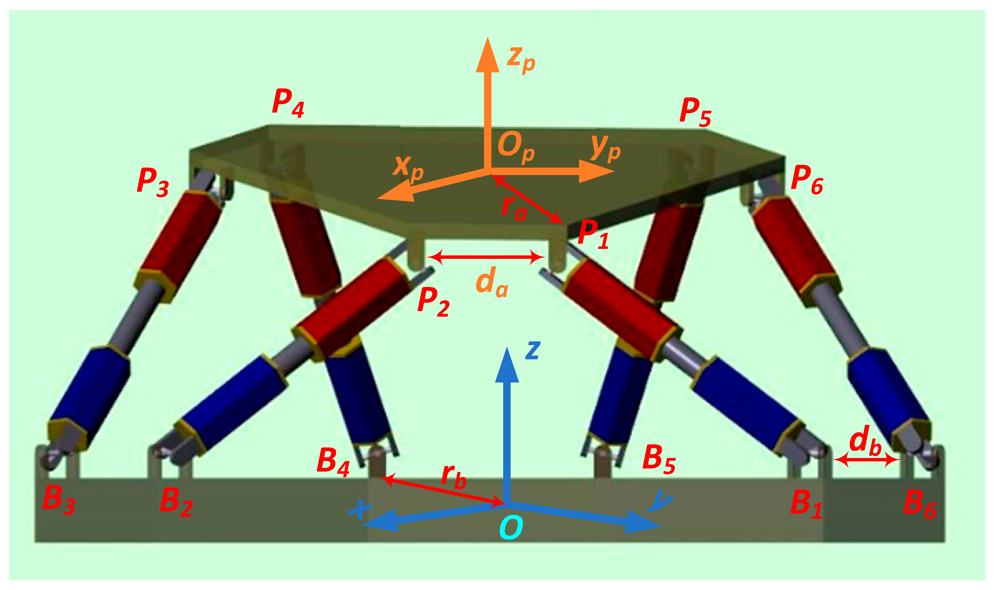
After the first publication by D. Stewart in 1965, many variants of this parallel mechanism have been developed by researchers. The unchanging common feature of these variants is the presence of six linearly operated legs with various leg platform connection combinations. The way the six legs are connected to the fixed base and the moving platform are the most important components that determine the wide range of motion and correct positioning of the mechanism. The type of joint chosen for the connection directly affects the robustness of the system and the amount of load it can carry [20,21]. The design of the Stewart platform supports a high load-bearing capacity. The design of the legs is sufficient to resist the compression and pulling forces to be applied to the base on the moving platform side and it does not bow to the unwanted bending force as in other parallel or serial mechanisms [22,23]. As shown in Figure 1, six legs are spaced around the upper movable plate and share the load equally on the top plate.
In this study, the Stewart platform was used as a solar tracker. It is necessary to apply the force to ensure that the sun rays coming on the planar photovoltaic panel placed on the movable plate of the Stewart platform are vertical at all hours of the day, appropriately, and in a timely manner on the six legs. We want to define the inputs and outputs of the system and the behavioural connections between them by constructing the non-linear system model to implement the desired control flag of the Stewart platform. The forces to be applied to the six legs in this mechanism are the inputs, and the length of each leg against this input and the speed of reaching this length are the outputs. The amount and duration of the forces to be applied to the inputs must be such that the electrical power obtained from the photovoltaic panel placed on the top plate is at maximum throughout the day. We can achieve this by detecting leg lengths, speeds, and current and voltage values of the photovoltaic panel with the help of sensors.
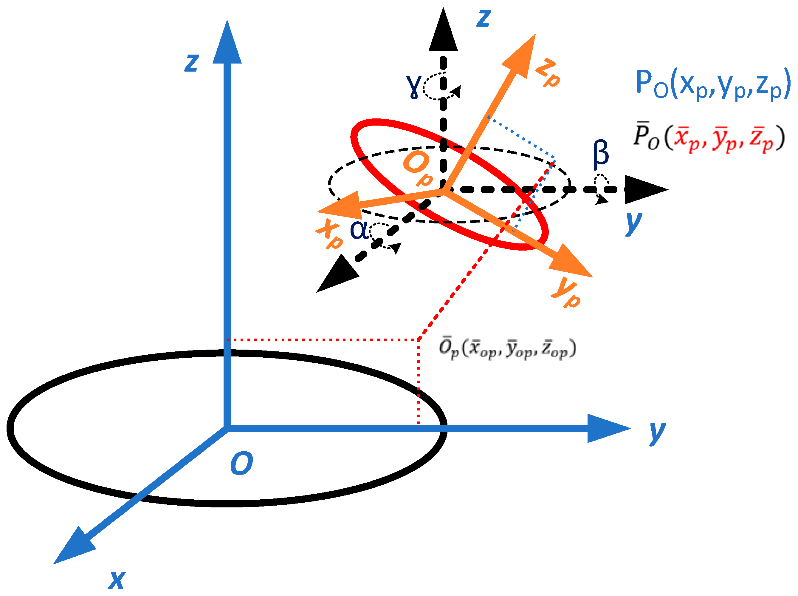
If we look at the mechanical construction of the Stewart platform, it consists of a fixed base, a movable plate, and six legs, as shown in Figure 1. A global coordinate system, O, is defined on the fixed base, and a local coordinate system, Op, is defined on the moving plate. Initially, the xpyp plane is parallel to the xy plane and the zp and z are perpendicular to the base and platform. As shown in Figure 2, Pi denotes the joints on the plate and Bi denotes the joints on the base. da refers to the gap between two adjacent joints located at the base, while db refers to the gap between two adjacent joints in the plate. The radius of the base is ra and the radius of the plate is rb.
To calculate the posture, q (), of the moving plate in the global coordinate system, in addition to the x, y, and z coordinate information, the Euler rotation angles roll, u, pitch, v, and yaw, w, should also be determined, as in Equation (1).
With the Lagrange’s equation in Equation (2), we can calculate the force that will provide the desired motion [24,25] without considering external disturbance and frictional forces.
is the inertia matrix, is the Coriolis and centrifugal force matrix, is the generalized force vector, and is the generalized force vector. We transfer point defined in the Op coordinate system to the base coordinate system, to the point .
T is the transfer matrix of a defined point on the platform to the base coordinate system.
R in Equation (4) is the Euler rotation matrix [26].
is distance between base joint Bi and moving plate joint Pi, which can be calculated using Equation (5).
To determine the leg lengths, , according to the posture, q, the relation between them is defined by Equation (6).
Equation (7) generalizes both sides of 6 legs and when its derivative is taken
J is the Jacobian matrix and is the leg length. The principle of virtual work gives opportunity to define leg length change, , with input force, , change of posture, , the generalized force vector [27].
Substituting Equation (7) into Equation (8) gives the generalized force vector .
The dynamic model is completed in Equation (10) by substituting the value obtained from Equation (9) into Equation (2) considering the external disturbance.
In Equation (10), the disturbance is added to the force applied to the input. This force is a force arising from environmental conditions and negatively affects the operation of the system. Its sign is sometimes the same as the force applied to the input, sometimes in the opposite direction. However, its sign was accepted as negative since its effect always causes deviation from the target.
2.2. Definition of Sun Attitude
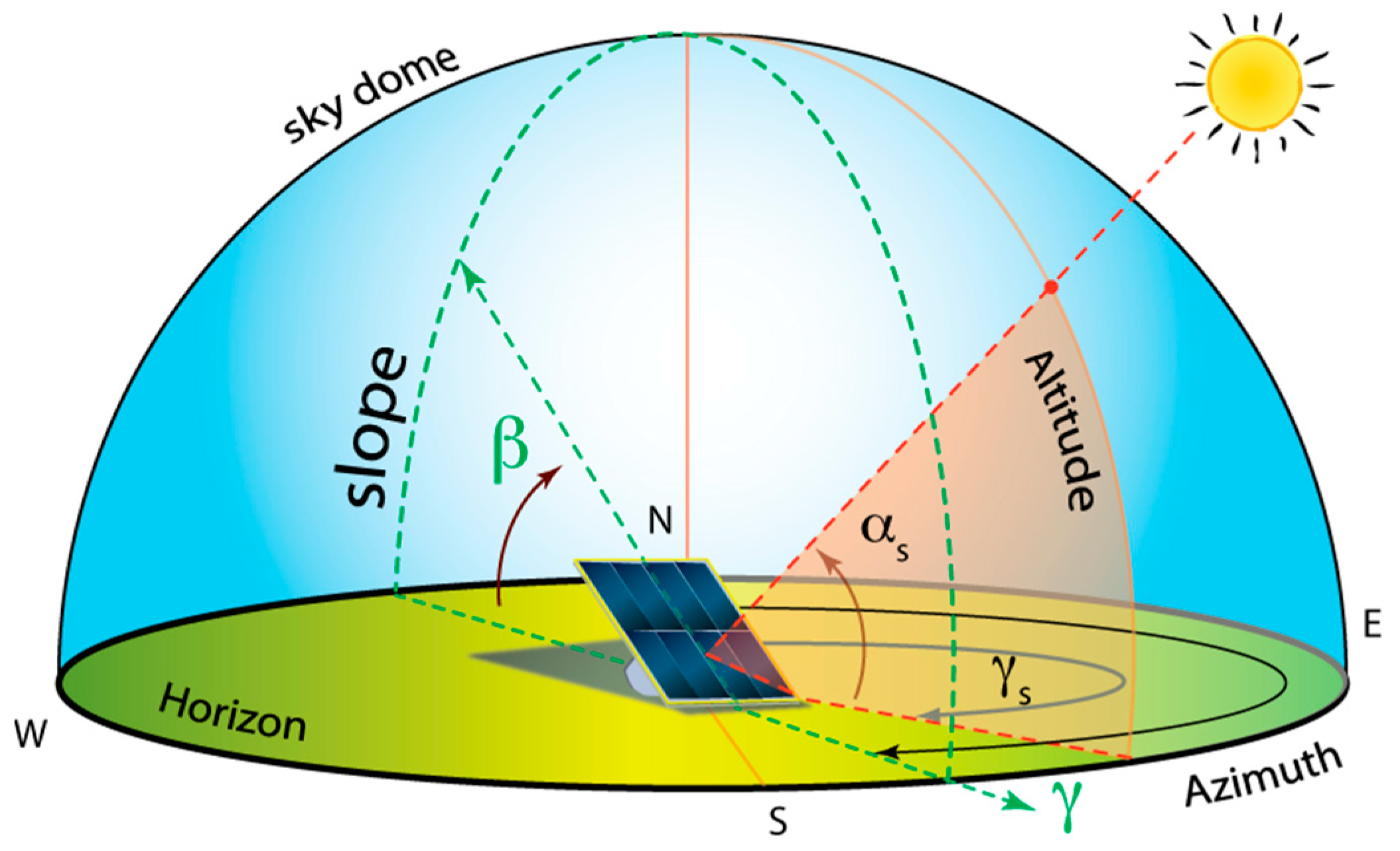
To obtain maximum power from the photovoltaic panel output throughout the day, the solar tracker must continuously monitor the sun throughout the day. To track accurately, the daily trajectory of the sun must be determined based on the time and location of the system. The sun rises from the east in the early hours of the morning and its angle with the horizontal increases throughout the day, reaching its maximum at noon. The sun continues to move in the west direction after noon and sets from the west in the evening hours, as shown in Figure 3. When we accept the sun’s rays as a single ray line, the angle between the horizon projection of this ray and the ray is called the elevation angle, α, of the sun. The angle that the projection of the ray makes with the eastern axis line is called the azimuth angle, [28]. The beginning of the azimuth angle is accepted as the north axis line in some of the literature.
The elevation angle determines the position of the sun on the vertical axis. To calculate this angle, we need to know the latitude angle, local time angle, and declination angle of the place where the system is installed. The elevation angle is calculated by substituting these values into Equation (11).
N is the day of the year. The azimuth angle, , which describes the motion of the sun in the horizontal plane, can be calculated with Equation (13) [8].
Using Equations (11)–(13), the daily trajectory of the sun can be obtained. Apart from these equations, the system needs latitude, longitude, and local time information of the place where it is installed.
2.3. Real-Time Embedded Controller
The solar tracker control algorithm is usually implemented by two methods. The first method is the open-loop control. In this method, the annual trajectory of the sun is calculated or written to the memory of the embedded controller as a look-up table at the desired resolution and the tracker adjusts the position of the photovoltaic panel relative to this trajectory and tries to provide maximum power generation. Since this method does not use sensors for feedback, installation and operating costs are lower. On the other hand, it continues to follow the sun even on cloudy and rainy days when the solar radiation is not sufficient for energy production. As a result, the energy consumption of the solar tracker becomes excessive and the net energy efficiency decreases. The second method is the closed-loop control. In this method, the controller measures the output variables, the input variables, and the position of the photovoltaic panel using appropriate sensors and determines its next move using these values. Installation and operating costs are high, but net energy efficiency is higher because it does not monitor the sun at unnecessary times. A hybrid mode of control utilizes the advantages of both open- and closed-loop control.
Yunfei et al., tried to control the Stewart platform mounted on the ship with a PID controller together with a feedforward speed compensator. While the proposed controller for light loads gave successful results, it could not provide sufficient control due to its inability to respond quickly enough to time-varying deteriorations under heavy load conditions. Researchers have proposed an adaptive robust controller using a recursive backstepping technique to overcome this problem [30].
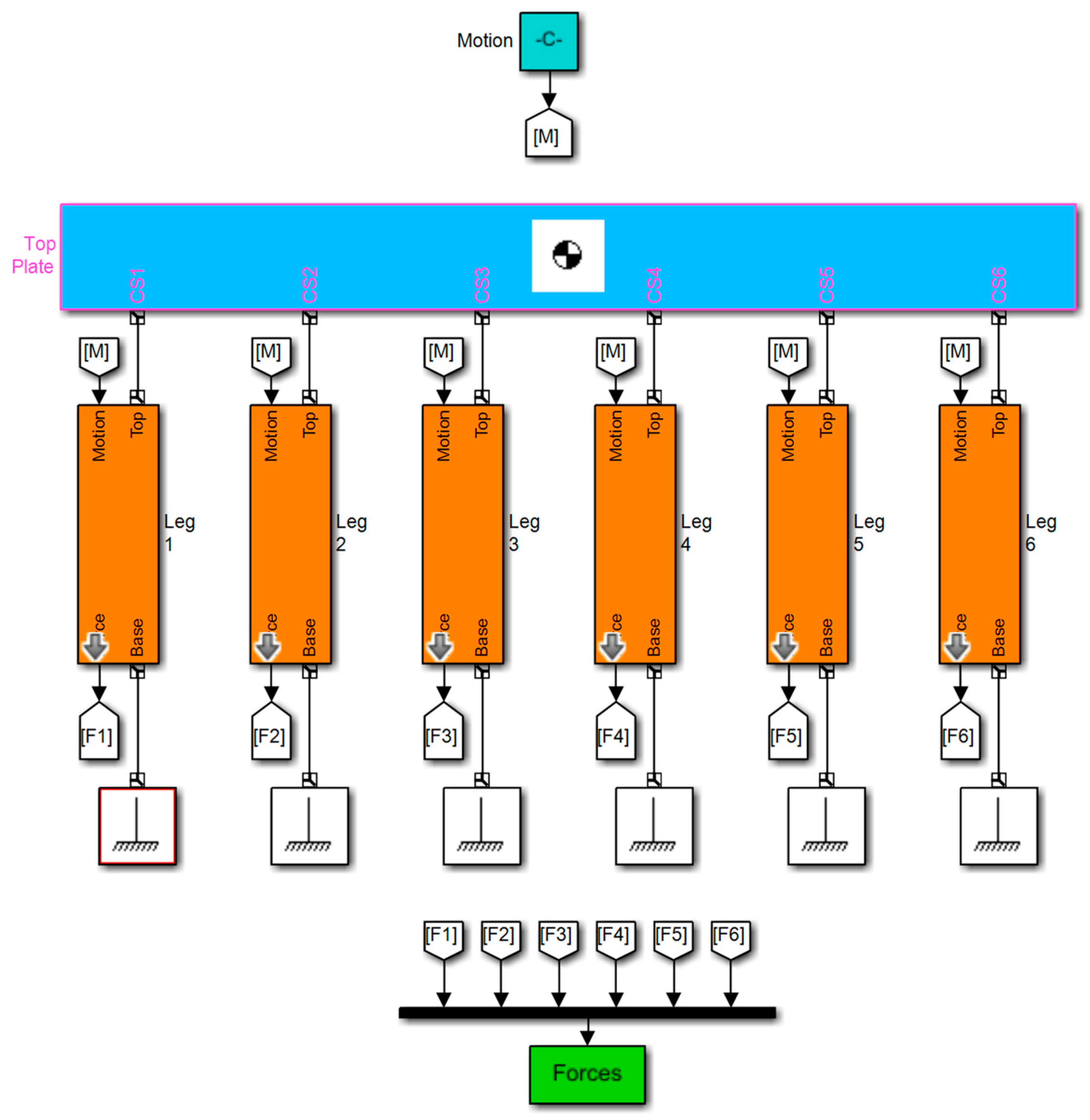
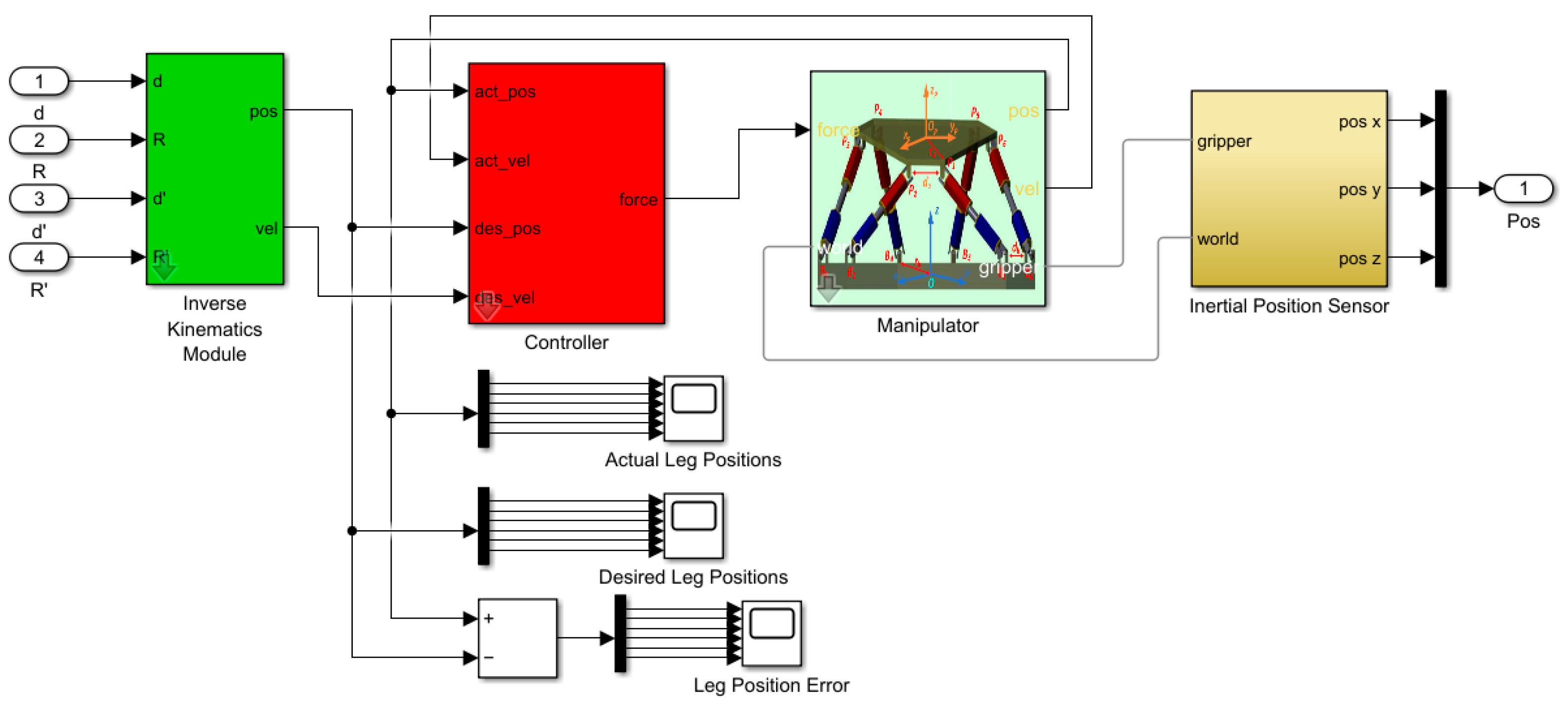
With the emergence of computational tools such as dynamic simulation software, it is now possible to easily model and simulate the mechanics of cyber physical systems together with the control system [31]. The Stewart platform’s MATLAB Simulink model was started by first developing the dynamic model we defined in Section 2.1, as shown in Figure 4. In the second stage, the controls were selected according to the control algorithm to be used and the Simulink model was created, as shown in Figure 5.
The PID controller provides a derivative term in addition to the proportional and integral terms. The derivative term is the time derivative of the error signal multiplied by a derivative constant Kd. The derivative term is proportional to the rate of change of error. It can increase the speed of system response. While the integral term stores the past error as a memory of the controller, the derivative term predicts future system behavior and can improve system stability. It can dampen oscillations and reduce settling time. However, the noises on the feedback and error signal will be amplified by the derivative operation. Additionally, the derivative term cannot have any effect on the steady state error itself because the derivative of a constant error will be zero. The general form of a PID controller has the following structure, where Td is the derivative time. The PID controller can act on the past, present, and future values of the system with the help of integral, proportional, and derivative terms.
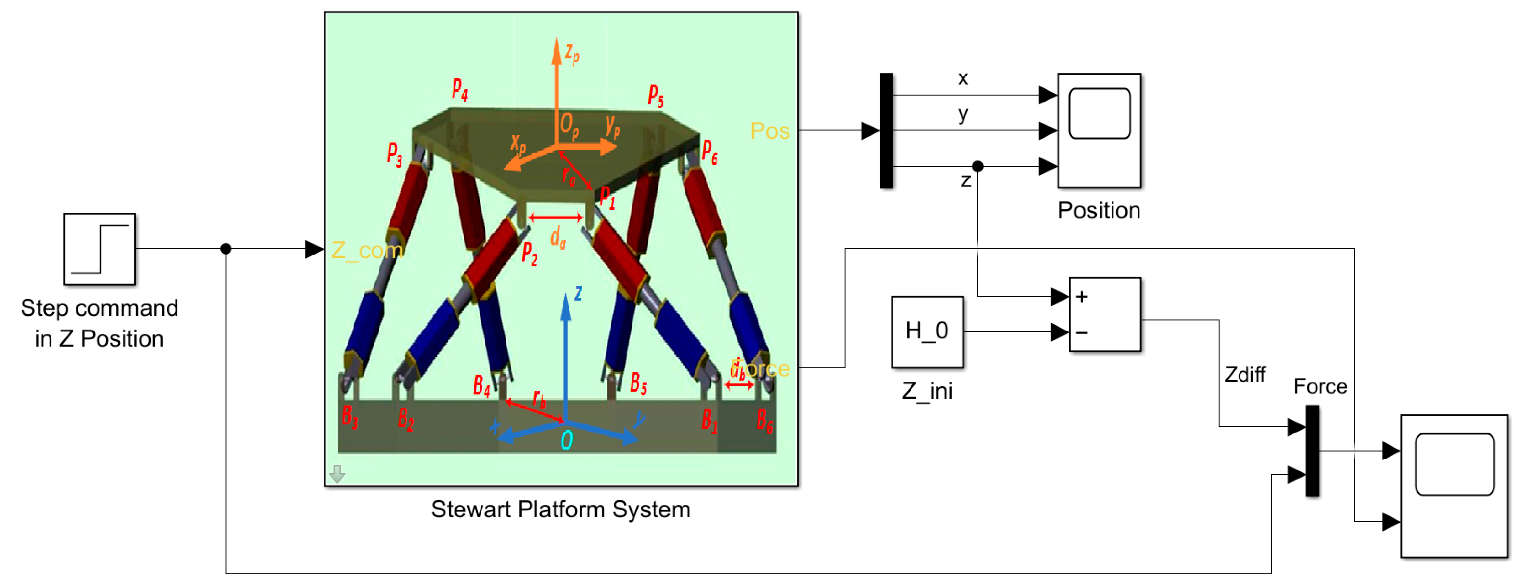
To test the performance of the designed PID controller and to tune its parameters, the step function was applied to the model, as shown in Figure 6. In the final stage, the mechanical and controller models were combined by adding appropriate sensors and output devices and the Simulink model of the system was completed, as shown in Figure 7.
2.4. Hardware Architecture
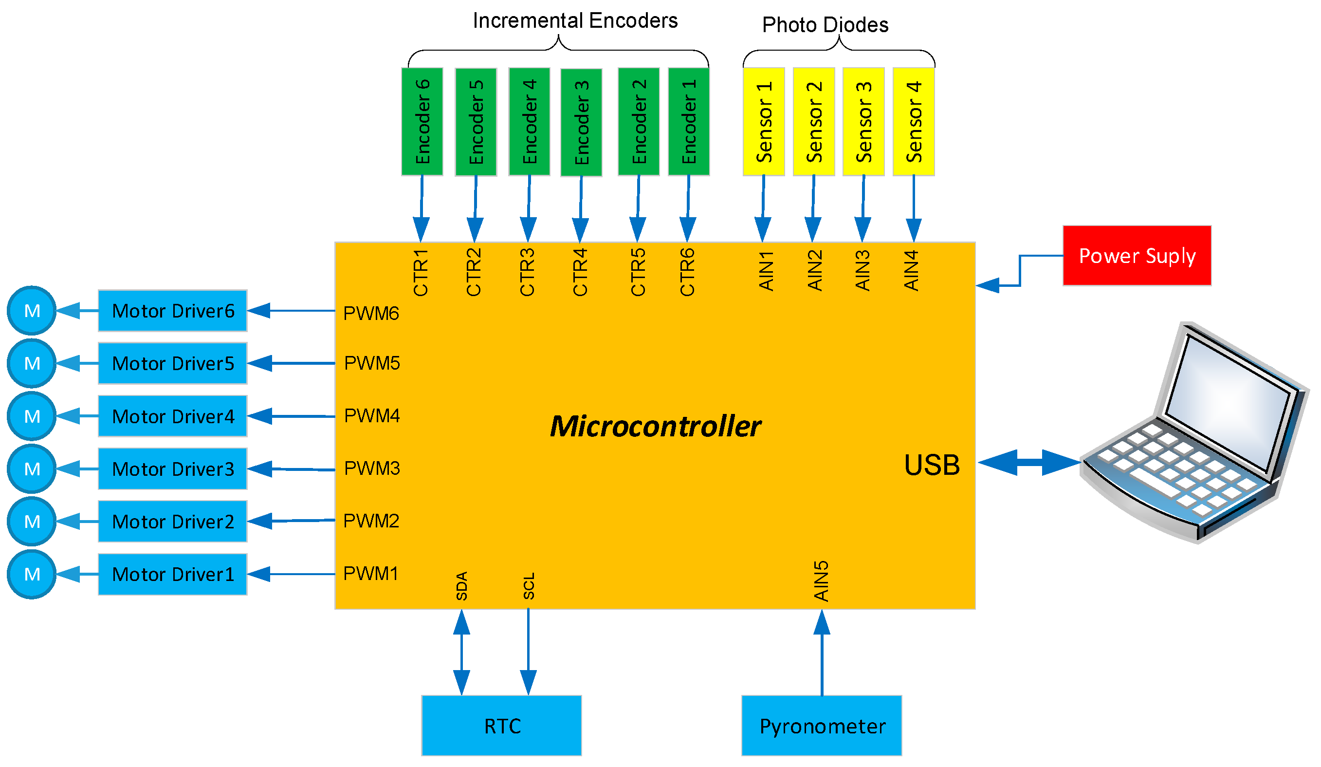
A typical embedded controller consists of hardware such as a microcontroller, a communication device, sensors, motor drives, linear actuators, and power supply. The linear actuator is a special mechanism that includes a DC motor, gear, incremental encoder, and low and high limit switches in the legs. An encoder which is placed on each linear actuator is used to measure the instant linear actuator velocity as a feedback source for motion control, whereas the limit switches are used for the detection of linear actuator maximum and minimum pitch, as our main target in this study is to implement an embedded controller for accurate position control of parallel mechanism. The hardware architecture of the embedded controller is shown in Figure 8. The sensors can communicate with the microcontroller using SPI, I2C, or UART communication hardware interfaces. The motors can be driven by motor drives using PWM signals generated by the microcontroller. An appropriate power supply is required as a power source for the devices.
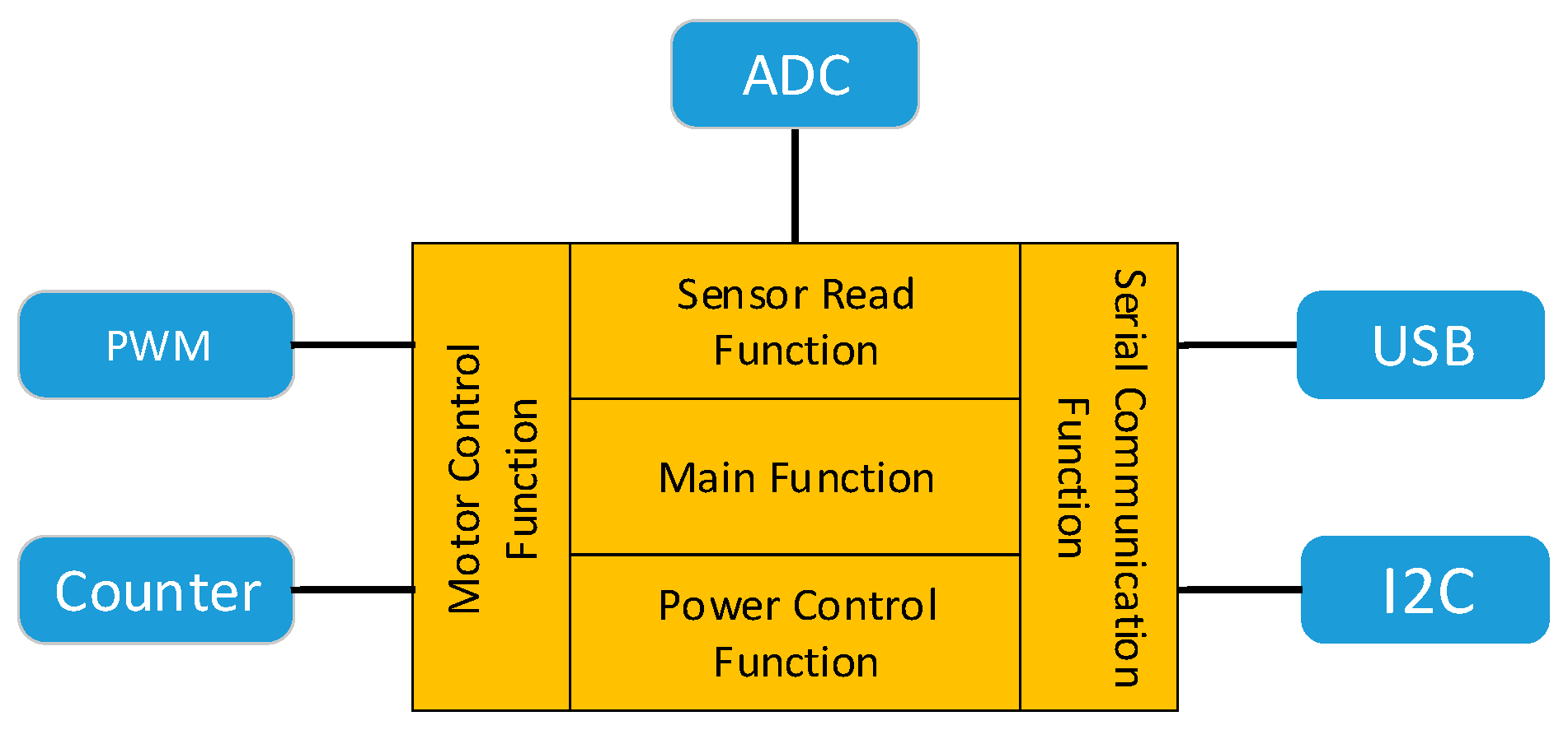
The software architecture of the embedded controller is shown in Figure 9. The firmware consists of motor control, sensor read, serial communication, power control, and main functions, all of which are executed on the microcontroller that is written in a system programming language such as embedded C.
The main function controls all the other functions and this unit takes input values and processes them according to the given algorithm and passes output values to the motor control function and user interface through the USB port. It calls the required function from related libraries and passes the parameters to accomplish a defined task. The sensor read function reads sensors and processes the sensor data, then passes the values to the main function. There is a sensor library to process the sensor data. The sensors are connected using any of the hardware connection interfaces to the microcontroller. Similarly, the main controller program communicates with the sensor library using user defined functions. The serial commination function is called for reading the real-time clock (RTC) unit to take time and date information and to communicate with the computer. This function can use USB, UART, SPI, and I2C serial communication interfaces. The motor control function generates a PWM signal according to the sun trajectory calculated by the main function. Additionally, this function reads the incremental encoders’ values and stores them in the function’s database to pass to the main function. The most important part of the firmware is the motor control function. After receiving the commands from the main function, it decomposes the speed for each motor. This module calculates a range of parameters (from 0 to 4095) of the required PWM signal. The microcontroller generates the required voltage to drive the motors with a targeted speed. Additionally, this module implements a PID controller as the low-level motor controller, where it receives the feedback from the motors’ incremental encoders.
3. Experimental Works
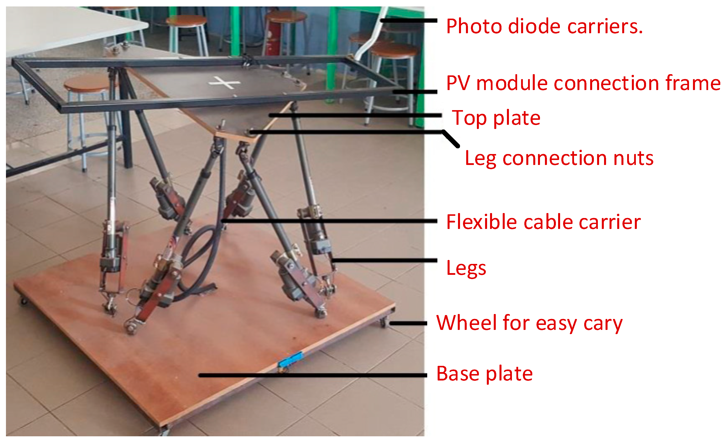
The system performance parameter for the solar tracker is the daily generated power. The generated power is usually compared with the power that is generated by the fixed PV system. The Stewart platform’s mechanical parts were designed according to the dynamic and the Simulink model and implemented as shown Figure 10.
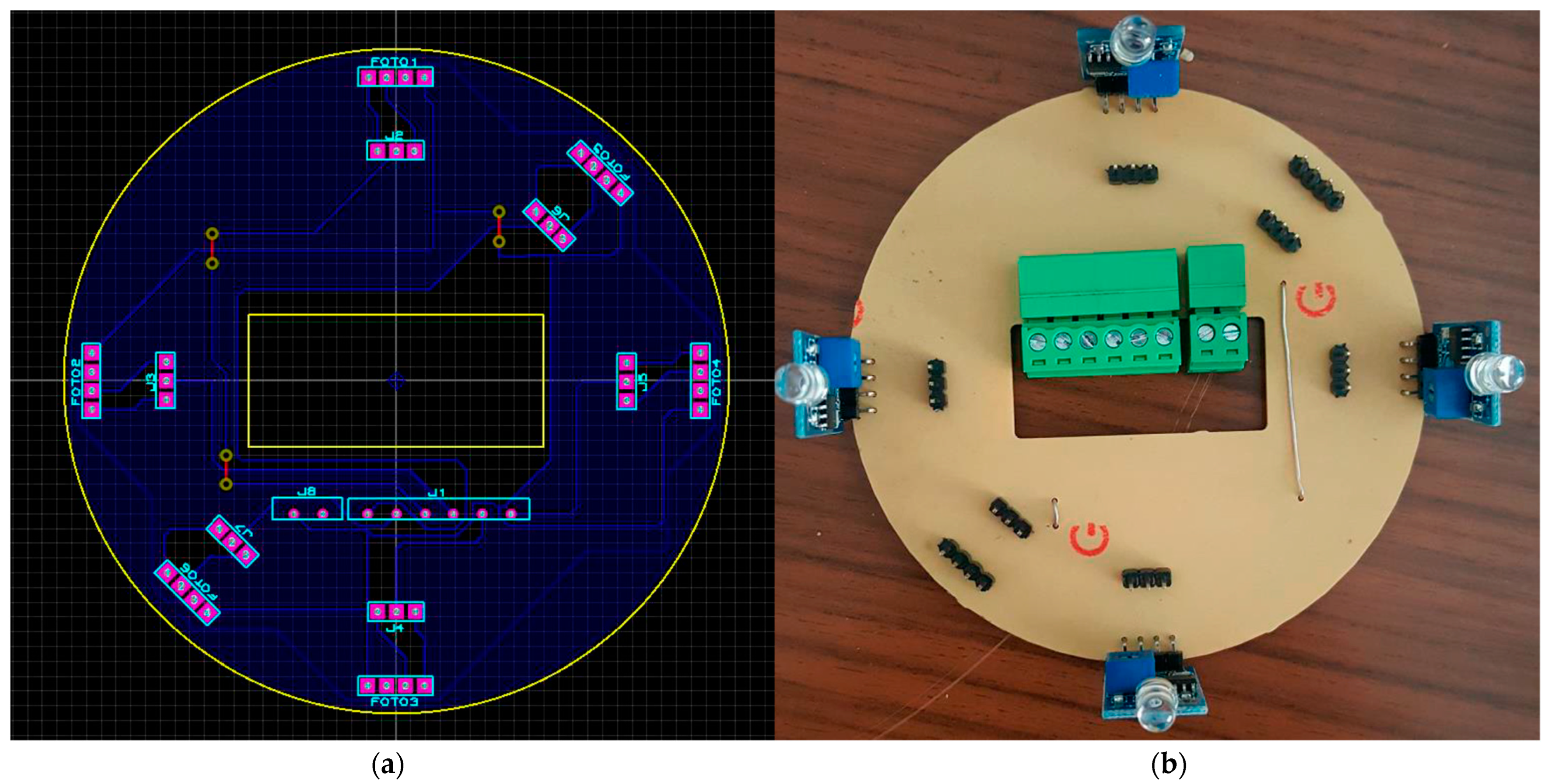
The motor control, sensor interface, and incremental encoder interface boards were designed using electronic CAD software. Then, printed circuit boards were produced and assembled as shown in Figure 11.
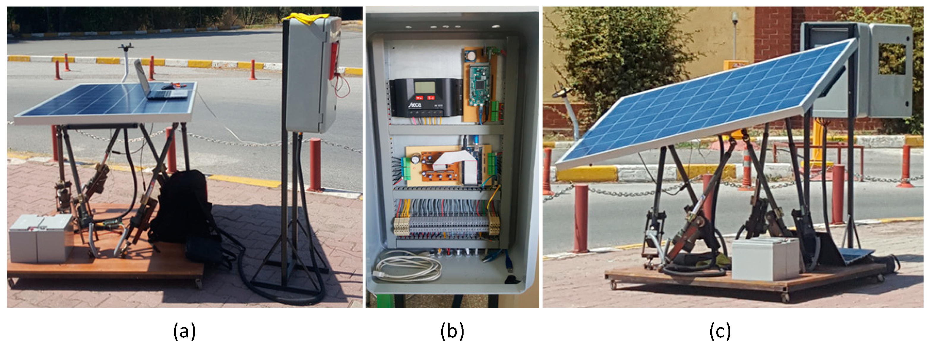
The system was assembled and tested outside and the system performance parameters were measured using a data logger. Figure 12 shows the installation of the solar tracker, the wiring control panel, and the PV module under testing.
4. Result and Discussion
The six degrees of freedom solar tracker accomplishes the active position adjustment of the photovoltaic panel to compensate for the solar tracker’s deviations caused by external disturbance variables such as wind and to precisely track the trajectory of the sun.
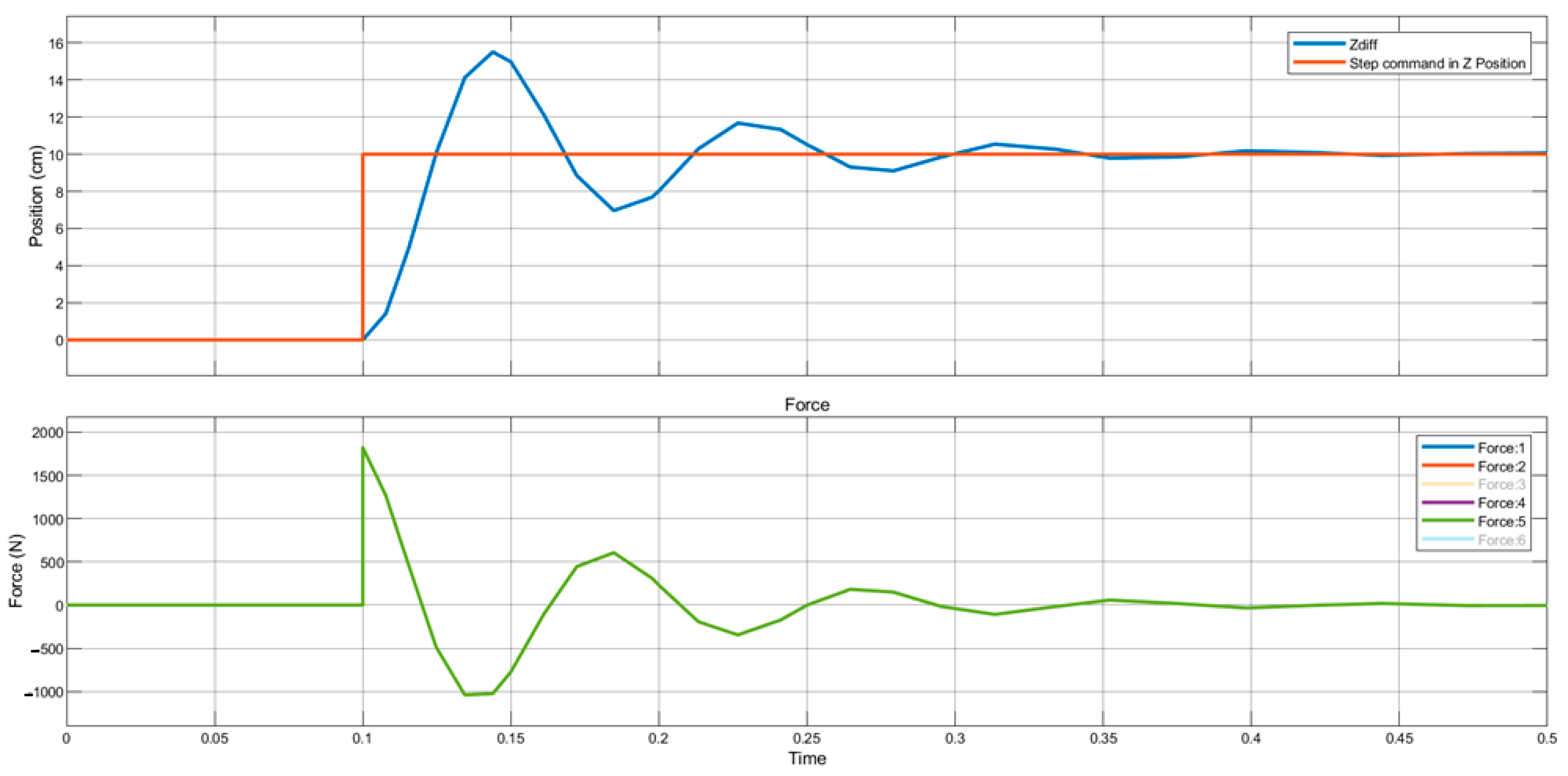
To test the performance of the designed PID controller and to tune its parameters, the step function was applied to the model as shown in Figure 6. Ki, Kp, and Kd gain values of the PID controller were determined by running Simulink’s PID tuner toolbox. By using those values, the step function that makes the moving plate rise 10 cm along the z-axis was applied to the Simulink model of the solar tracker as an input. The response of the system and the change in the force applied to each leg are given in Figure 13. As shown in the figure, the system reached equilibrium in 0.35 s. Since the movement is along the z-axis, the same force was applied to each leg at the same time, since the moving plate only rose 10 cm vertically.
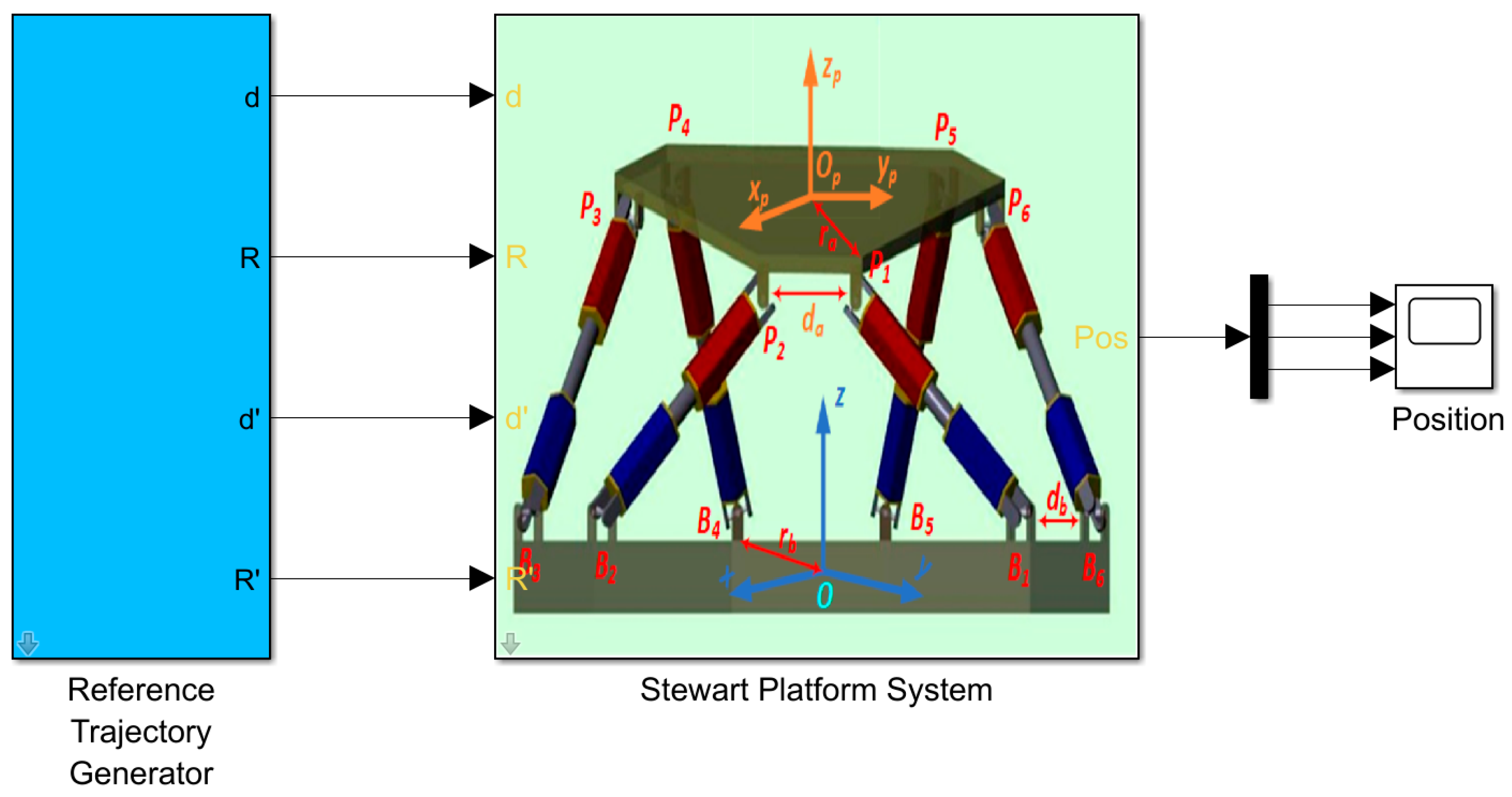
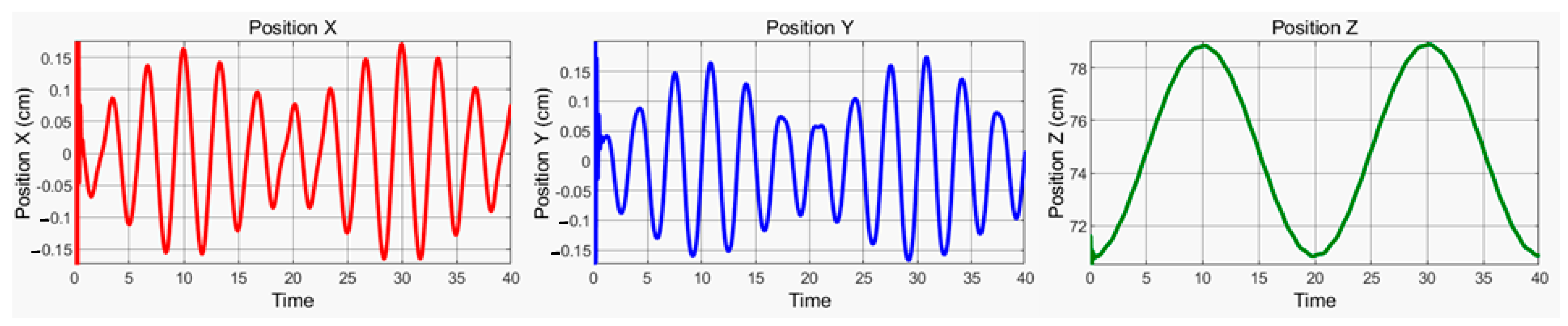
The solar tracker Simulink model in Figure 6 was simulated by applying a similar entry to the daily solar trajectory described in Section 2.2. During the simulation, the positions of the six legs of the Stewart platform, the position errors, and the changes in the forces applied to the legs over time were recorded and shown in Figure 14.
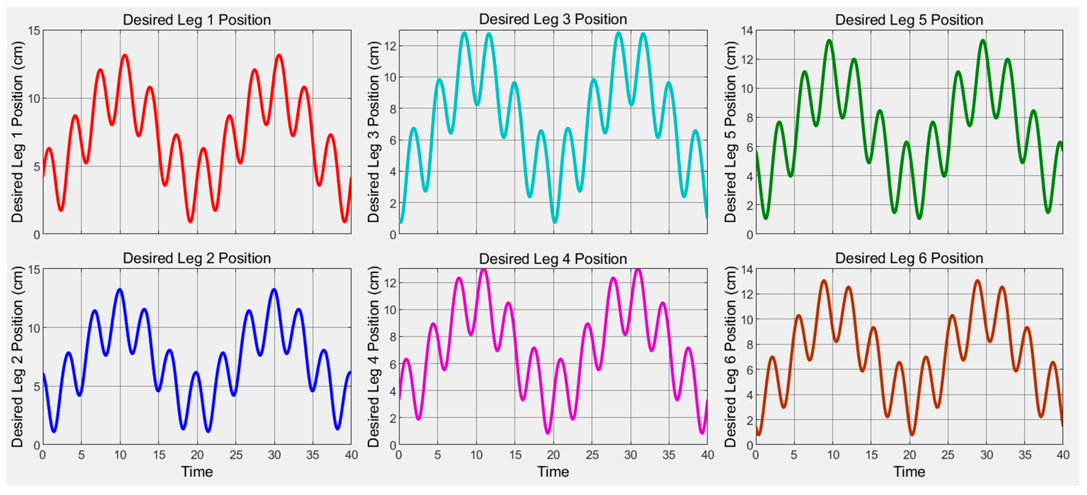
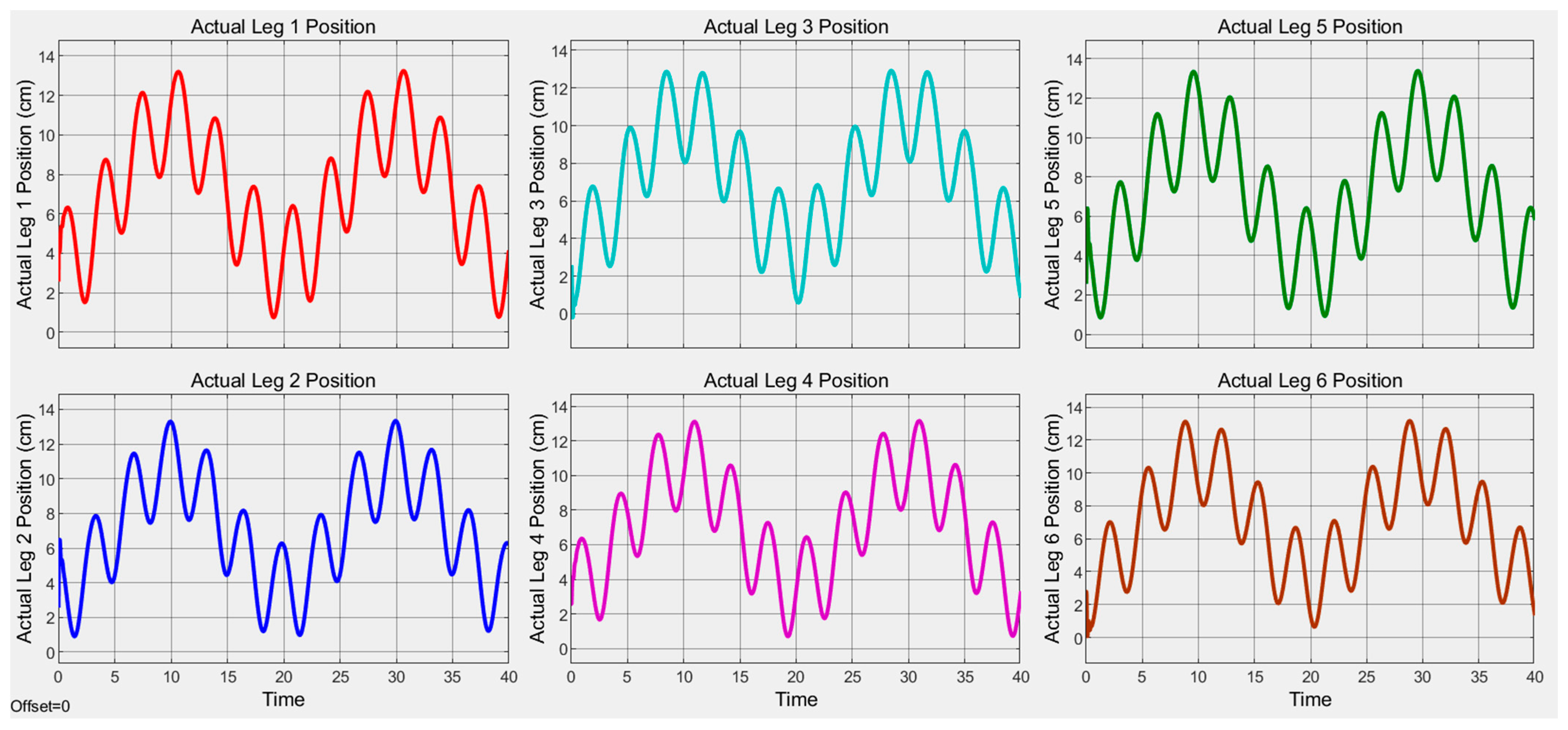
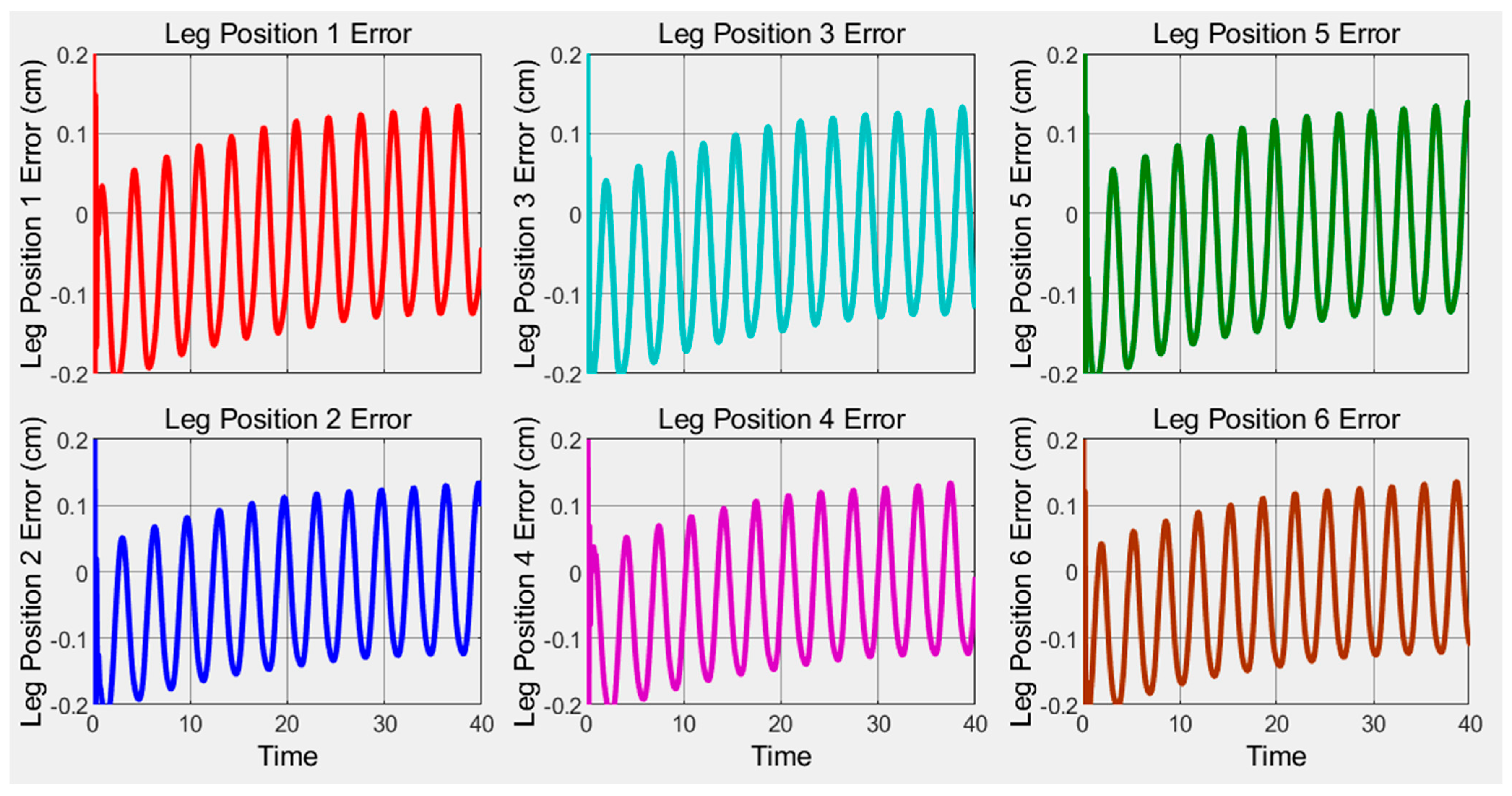
The designed solar tracker was first simulated in Simulink. Because the photovoltaic panel could not be placed on the Stewart platform in Simulink, the power generation, which is the actual output variable of the system, could not be examined. For this reason, the lengths of the six legs, which are the output variables of the dynamic model, were examined. The desired leg lengths were calculated by the model and are shown in Figure 15. By applying a force input close to the sun’s trajectory to the input of the Simulink model, the lengths of the legs were measured from the output and are shown in Figure 16. The measured lengths were compared with the lengths desired by the model and the differences between them in cm are shown in Figure 17. As can be seen from this graph, the amount of error did not exceed ±0.2 cm.
The tracking algorithm used in the sun-tracking phase first calculated the sun’s elevation and azimuth angles. After the angles were found, the leg lengths of the Stewart platform that provide these angles were calculated. The controller brought the movement that provides these lengths to the desired value by adjusting the current applied to the motors. When we calculated the deviations that may occur in the angle values based on the error values in the leg lengths, 0.2049 degrees was obtained. The accuracy obtained for the solar tracker made with the parallel mechanism in the literature is given as below 2 degrees and it is stated that this value is sufficient accuracy for the solar tracker [17]. Poulek et al., stated that 10 degrees of angle accuracy for the dual axis solar tracker they designed with the serial mechanism is sufficient to convert 93% of the potential energy into electrical energy [32].
To determine the ability to follow the desired trajectory in harsh environmental conditions, we increased the weight of the moving plate in the Simulink model of the Stewart platform shown in Figure 5 to represent the effect of the wind on the photovoltaic panel. The effect of the wind on the panel depends on the instantaneous angle of the panel, the speed of the wind, and the air density of the environment [33,34]. Equation (14) is used to calculate the load effect that the wind will make on the panel [35].
Here, F is the force of the wind on the photovoltaic panel (N), u is the wind speed (m/s), A is the surface area of the photovoltaic panel (m2), and is the air density (kg/m3). As it can be understood from the equation, if the solar tracker is in a horizontal position, the theoretical affecting force should be zero, but, in this case, the lateral area of the photovoltaic panel about 5 cm high and 2 m long will not be zero in practice because it will stand perpendicular to the wind. Apart from wind, another challenging environmental condition that the solar tracker will encounter is snow or rain. Since there will be no sun during snow or rain, the solar tracker will mostly be in a resting position.
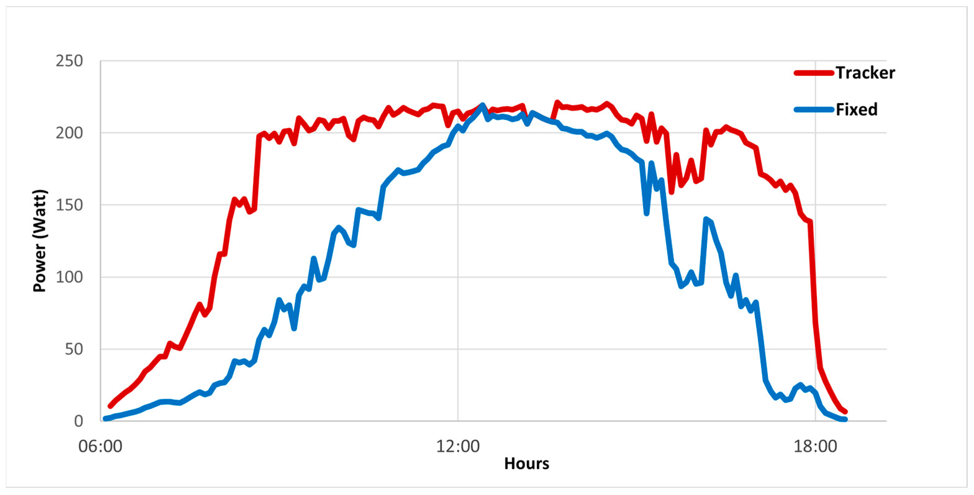
Using the measured data system, the output power was calculated and compared with the fixed one. Figure 18 shows the solar tracker and the fixed PV systems’ daily changes of the generated power. Results shows that the solar tracker generated 32.5% more energy.
5. Conclusions
A wind-resistant solar tracker was designed and constructed. To enhance the energy gain performance of a solar tracking system, a PID control algorithm has been developed. Variables determining and affecting system’s energy gain were measured and recorded for analysis. The 6-DoF tracking parallel mechanism exhibited a better performance, with an increase in the collected energy of about 32.5% compared with the fixed surface.
As possible future studies, new studies on kinematics, dynamic models, and control algorithms that we could not achieve adequately during this research are our target. The kinematic singularities of the developed Stewart platform can be found analytically to be used in the design of the desired trajectories. It may be a future study to create a new dynamic model that incorporates the effects of disturbance variables and friction into the developed Stewart platform dynamic model more successfully. Designing optimal and advanced artificial neural network-based control algorithms to improve monitoring performance is another future study target.
Funding
This research received no external funding.
Data Availability Statement
Not applicable.
Conflicts of Interest
The authors declare no conflict of interest.
References
- Clifford, M.; Eastwood, D. Design of a novel passive solar tracker. Sol. Energy 2004, 77, 269–280. [Google Scholar] [CrossRef]
- Schultz, H.S.; Carvalho, M. Design, Greenhouse Emissions, and Environmental Payback of a Photovoltaic Solar Energy System. Energies 2022, 15, 6098. [Google Scholar] [CrossRef]
- Rigo, P.D.; Siluk, J.C.M.; Lacerda, D.P.; Spellmeier, J.P. Competitive business model of photovoltaic solar energy installers in Brazil. Renew. Energy 2022, 181, 39–50. [Google Scholar] [CrossRef]
- Boukdir, Y.; El Omari, H. Characterization of cadmium sulfide light dependent resistors sensors for optical solar trackers. Int. J. Electr. Comput. Eng. 2023, 13, 184–194. [Google Scholar] [CrossRef]
- Mourad, A.-H.I.; Shareef, H.; Ameen, N.; Alhammadi, A.H.; Iratni, M.; Alkaabi, A.S. A state-of-the-art review: Solar trackers. In Proceedings of the 2022 Advances in Science and Engineering Technology International Conferences, ASET 2022, Dubai, United Arab Emirates, 21–24 February 2022; pp. 1–5. [Google Scholar] [CrossRef]
- Al-Amayreh, M.I.; Alahmer, A. On improving the efficiency of hybrid solar lighting and thermal system using dual-axis solar tracking system. Energy Rep. 2022, 8, 841–847. [Google Scholar] [CrossRef]
- Nsengiyumva, W.; Chen, S.G.; Hu, L.; Chen, X. Recent advancements and challenges in Solar Tracking Systems (STS): A review. Renew. Sustain. Energy Rev. 2018, 81, 250–279. [Google Scholar] [CrossRef]
- Wu, C.-H.; Wang, H.-C.; Chang, H.-Y. Dual-axis solar tracker with satellite compass and inclinometer for automatic positioning and tracking. Energy Sustain. Dev. 2022, 66, 308–318. [Google Scholar] [CrossRef]
- Vargas, A.N.; Francisco, G.R.; Montezuma, M.A.; Sampaio, L.P.; Acho, L. Low-cost dual-axis solar tracker with photovoltaic energy processing for education. Sustain. Energy Technol. Assess. 2022, 53, 102542. [Google Scholar] [CrossRef]
- Kazezkhan, G.; Xiang, B.; Wang, N.; Yusup, A. Dynamic modeling of the Stewart platform for the NanShan Radio Telescope. Adv. Mech. Eng. 2020, 12, 1687814020940072. [Google Scholar] [CrossRef]
- Dunlop, G.; Jones, T. Position analysis of a two DOF parallel mechanism—the Canterbury tracker. Mech. Mach. Theory 1999, 34, 599–614. [Google Scholar] [CrossRef]
- Han, B.; Xu, Y.; Yao, J.; Zheng, D.; Li, Y.; Zhao, Y. Design and analysis of a scissors double-ring truss deployable mechanism for space antennas. Aerosp. Sci. Technol. 2019, 93, 105357. [Google Scholar] [CrossRef]
- Qiu, D.; Sun, M.; Wang, Z.; Wang, Y.; Chen, Z. Practical Wind-Disturbance Rejection for Large Deep Space Observatory Antenna. IEEE Trans. Control. Syst. Technol. 2014, 22, 1983–1990. [Google Scholar] [CrossRef]
- Itul, T.; Pisla, D. Dynamics of a 3-DOF parallel mechanism used for orientation applications. In Proceedings of the 2008 IEEE International Conference on Automation, Quality and Testing, Robotics, AQTR 2008-THETA 16th Edition-Proceedings, Cluj-Napoca, Romania, 22–25 May 2008; Volume 2, pp. 398–403. [Google Scholar] [CrossRef]
- Song, Y.; Qi, Y.; Dong, G.; Sun, T. Type synthesis of 2-DoF rotational parallel mechanisms actuating the inter-satellite link antenna. Chin. J. Aeronaut. 2016, 29, 1795–1805. [Google Scholar] [CrossRef] [Green Version]
- Sun, J.; Shao, L.; Fu, L.; Han, X.; Li, S. Kinematic analysis and optimal design of a novel parallel pointing mechanism. Aerosp. Sci. Technol. 2020, 104, 105931. [Google Scholar] [CrossRef]
- Du, X.; Li, Y.; Wang, P.; Ma, Z.; Li, D.; Wu, C. Design and optimization of solar tracker with U-PRU-PUS parallel mechanism. Mech. Mach. Theory 2021, 155, 104107. [Google Scholar] [CrossRef]
- Yang, G.; Yao, J.; Dong, Z. Neuroadaptive learning algorithm for constrained nonlinear systems with disturbance rejection. Int. J. Robust Nonlinear Control. 2022, 32, 6127–6147. [Google Scholar] [CrossRef]
- Yadavari, H.; Aghaei, V.T.; Ikizoglu, S. Deep Reinforcement Learning based Control of Stewart Platform with Parametric Simulation in ROS and Gazebo. J. Mech. Robot. 2023, 15, 035001. [Google Scholar] [CrossRef]
- Furqan, M.; Suhaib, M.; Ahmad, N. Studies on Stewart platform manipulator: A review. J. Mech. Sci. Technol. 2017, 31, 4459–4470. [Google Scholar] [CrossRef]
- Shim, S.; Lee, S.; Joo, S.; Seo, J. Denavit-Hartenberg Notation-Based Kinematic Constraint Equations for Forward Kinematics of the 3–6 Stewart Platform. J. Mech. Robot. 2022, 14, 054505. [Google Scholar] [CrossRef]
- Stewart, D. A Platform with Six Degrees of Freedom. In Proceedings of the Institution of Mechanical Engineers, London, UK, 1 June 1965; Volume 180, pp. 371–386. [Google Scholar] [CrossRef]
- Chauhan, D.K.S.; Vundavilli, P.R. Forward Kinematics of the Stewart Parallel Manipulator Using Machine Learning. Int. J. Comput. Methods 2022, 19, 1–22. [Google Scholar] [CrossRef]
- Zhu, H.; Xu, W.; Yu, B.; Ding, F.; Cheng, L.; Huang, J. A Novel Hybrid Algorithm for the Forward Kinematics Problem of 6 DOF Based on Neural Networks. Sensors 2022, 22, 5318. [Google Scholar] [CrossRef] [PubMed]
- Wang, Q.; Su, J.; Lv, Z.; Zhang, L.; Lin, H.; Xu, G. Efficient hybrid method for forward kinematics analysis of parallel robots based on signal decomposition and reconstruction. Adv. Mech. Eng. 2017, 9, 1687814017699094. [Google Scholar] [CrossRef] [Green Version]
- Navvabi, H.; Markazi, A.H. Hybrid position/force control of Stewart Manipulator using Extended Adaptive Fuzzy Sliding Mode Controller (E-AFSMC). ISA Trans. 2018, 88, 280–295. [Google Scholar] [CrossRef] [PubMed]
- Zhou, Y.; She, J.; Wang, F.; Iwasaki, M. Disturbance Rejection for Stewart Platform Based on Integration of Equivalent-Input-Disturbance and Sliding-Mode Control Methods. In IEEE/ASME Transactions on Mechatronics; IEEE: Piscataway, NJ, USA, 2023; pp. 1–11. [Google Scholar] [CrossRef]
- Reindl, D.; Beckman, W.; Duffie, J. Evaluation of hourly tilted surface radiation models. Sol. Energy 1990, 45, 9–17. [Google Scholar] [CrossRef]
- Roth, P.; Georgiev, A.; Boudinov, H. Cheap two axis sun following device. Energy Convers. Manag. 2005, 46, 1179–1192. [Google Scholar] [CrossRef]
- Zhao, C.; Yu, C.; Yao, J. Dynamic Decoupling Based Robust Synchronous Control for a Hydraulic Parallel Manipulator. IEEE Access 2019, 7, 30548–30562. [Google Scholar] [CrossRef]
- Klein, B. Creating a Stewart Platform Model Using SimMechanics—MATLAB & Simulink. Available online: https://www.mathworks.com/company/newsletters/articles/creating-a-stewart-platform-model-using-simmechanics.html (accessed on 2 March 2023).
- Poulek, V.; Libra, M. New solar tracker. Sol. Energy Mater. Sol. Cells 1998, 51, 113–120. [Google Scholar] [CrossRef]
- Peng, H.; Dai, S.; Liu, H. Wind loading characteristics and roof zoning of solar arrays mounted on flat-roofed tall buildings. J. Build. Eng. 2023, 66, 105823. [Google Scholar] [CrossRef]
- Alrawashdeh, H.; Stathopoulos, T. Wind loads on solar panels mounted on flat roofs: Effect of geometric scale. J. Wind. Eng. Ind. Aerodyn. 2020, 206, 104339. [Google Scholar] [CrossRef]
- Jiang, G.; Zhao, Y.; Liu, J.; Jiang, H. Calculation of Wind Load on Photovoltaic Panel of Solar Power Plant. In Proceedings of the 2020 5th International Conference on Power and Renewable Energy, ICPRE 2020, Shanghai, China, 12–14 September 2020; pp. 558–561. [Google Scholar] [CrossRef]
Figure 1.
Structure of the Stewart platform.

Figure 2.
Coordinate transformation.

Figure 3.
Fixed aperture with its orientation defined by the tilt angle (β) and the aperture azimuth angle (γ).
Figure 3.
Fixed aperture with its orientation defined by the tilt angle (β) and the aperture azimuth angle (γ).

Figure 4.
Simulink model of the Stewart platform.

Figure 5.
Simulink model of the PID controller and the inverse kinematics module.

Figure 6.
Simulink model of the controller and the applied step input for Z axis.

Figure 7.
General Simulink model of the system simulator.

Figure 8.
Hardware architecture of the embedded controller.

Figure 9.
A brief description of the software architecture.

Figure 10.
Mechanical structure of the Stewart platform for sun tracking application.

Figure 11.
(a) Sensor board CAD view. (b) Assembled sensor board.

Figure 12.
(a) Installation of the solar tracker, (b) wiring control panel, (c) testing of the solar tracker.
Figure 12.
(a) Installation of the solar tracker, (b) wiring control panel, (c) testing of the solar tracker.

Figure 13.
PID controller step input response and force on six legs during simulation time.

Figure 14.
Moving plate position simulation results for a given reference sun trajectory.

Figure 15.
Desired leg position simulation results for reference trajectory.

Figure 16.
Actual leg position simulation results for reference trajectory.

Figure 17.
Leg position error simulation results for reference trajectory.

Figure 18.
Daily generated power changes of the solar tracker and the fixed PV system.

Disclaimer/Publisher’s Note: The statements, opinions and data contained in all publications are solely those of the individual author(s) and contributor(s) and not of MDPI and/or the editor(s). MDPI and/or the editor(s) disclaim responsibility for any injury to people or property resulting from any ideas, methods, instructions or products referred to in the content. |
© 2023 by the author. Licensee MDPI, Basel, Switzerland. This article is an open access article distributed under the terms and conditions of the Creative Commons Attribution (CC BY) license (https://creativecommons.org/licenses/by/4.0/).
Share and Cite
MDPI and ACS Style
Engin, M. Controller Design for Parallel Mechanism Solar Tracker. Machines 2023, 11, 372. https://doi.org/10.3390/machines11030372
AMA Style
Engin M. Controller Design for Parallel Mechanism Solar Tracker. Machines. 2023; 11(3):372. https://doi.org/10.3390/machines11030372
Chicago/Turabian StyleEngin, Mustafa. 2023. "Controller Design for Parallel Mechanism Solar Tracker" Machines 11, no. 3: 372. https://doi.org/10.3390/machines11030372
Note that from the first issue of 2016, this journal uses article numbers instead of page numbers. See further details here.