
Effect of Hardening Temperature on Maraging Steel Samples Prepared by Direct Metal Laser Sintering Process

Abstract
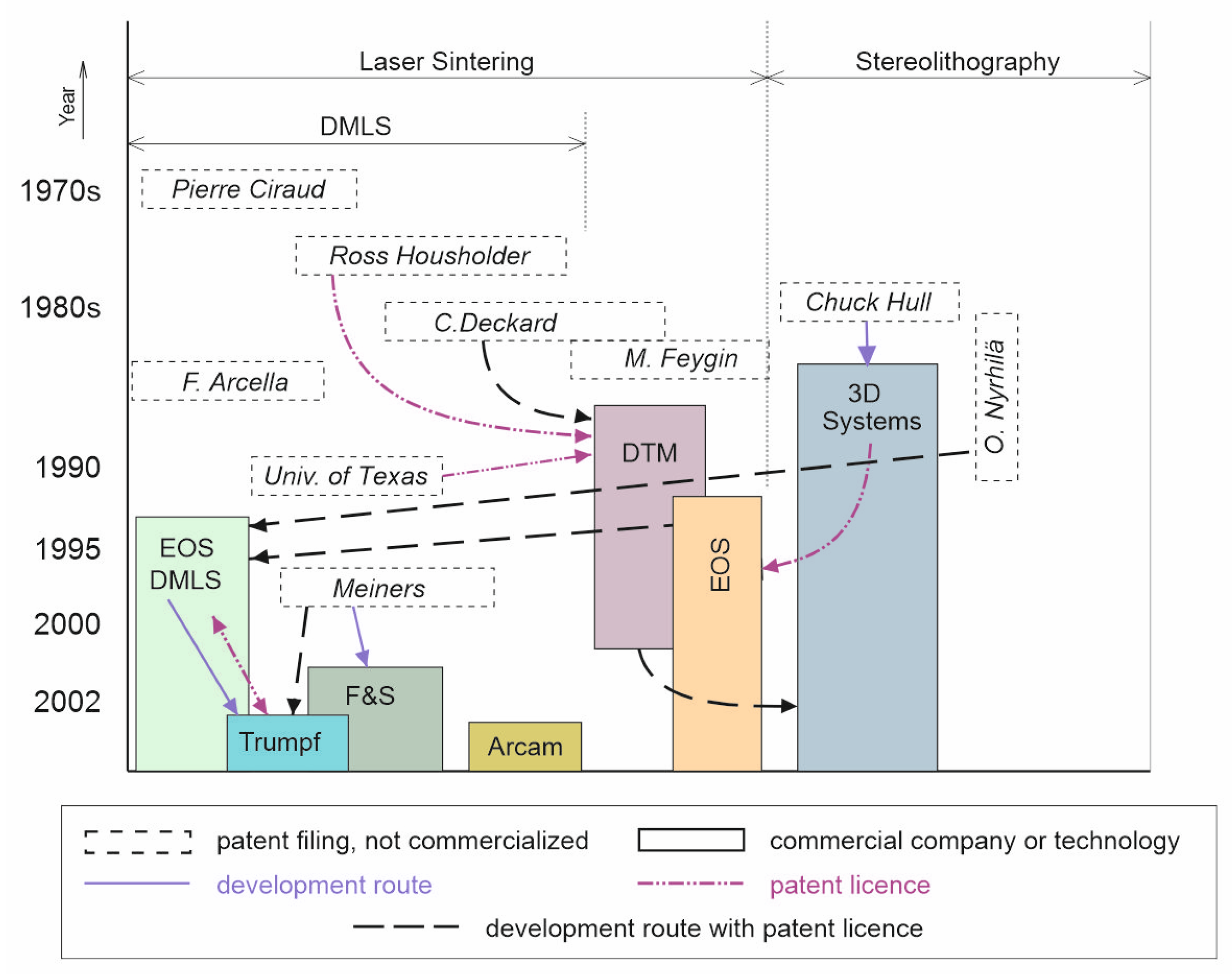
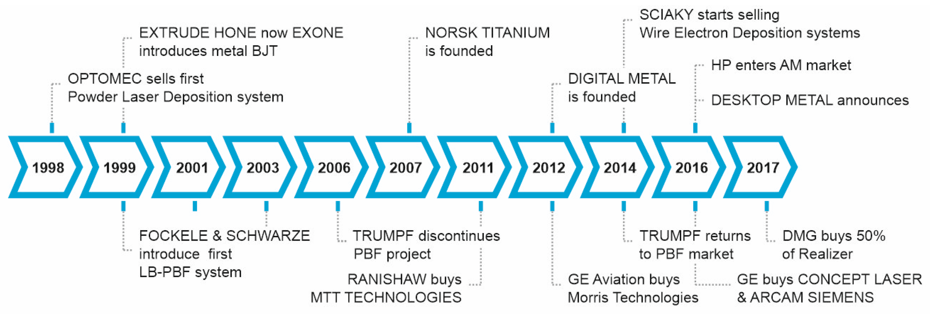
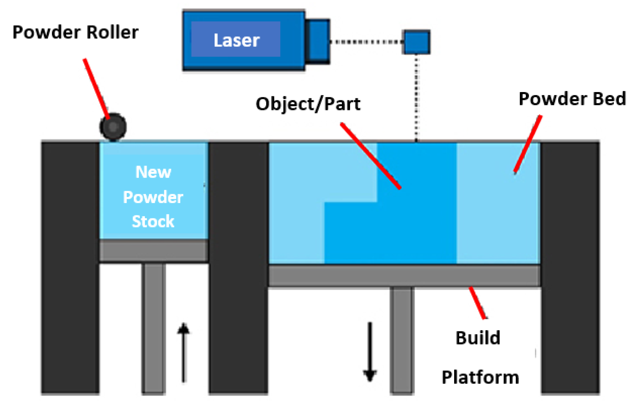
:1. Introduction
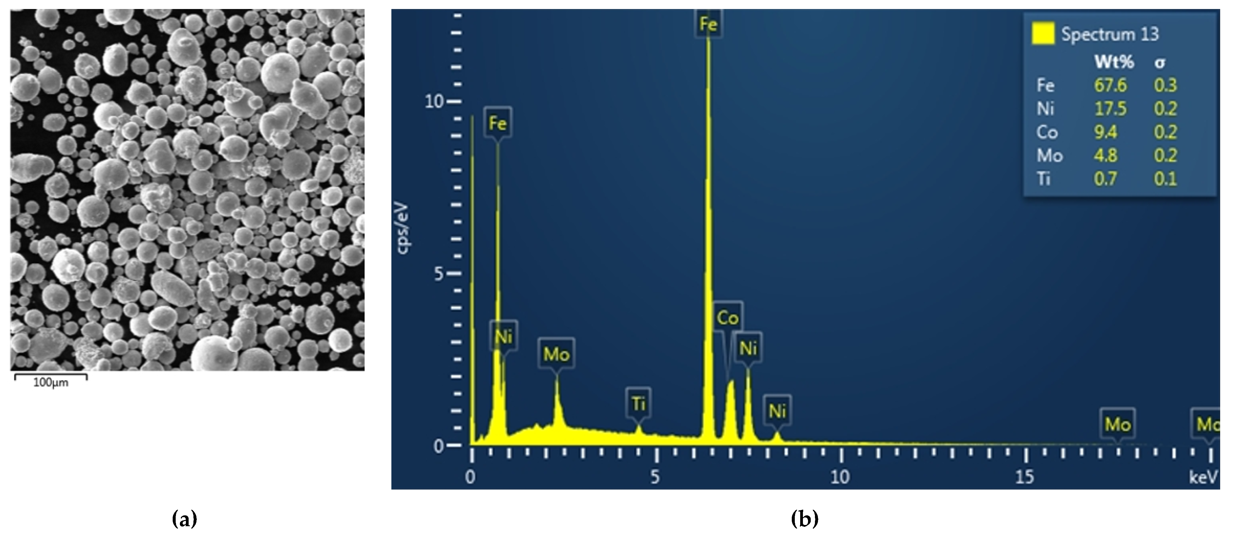
2. Materials and Methods
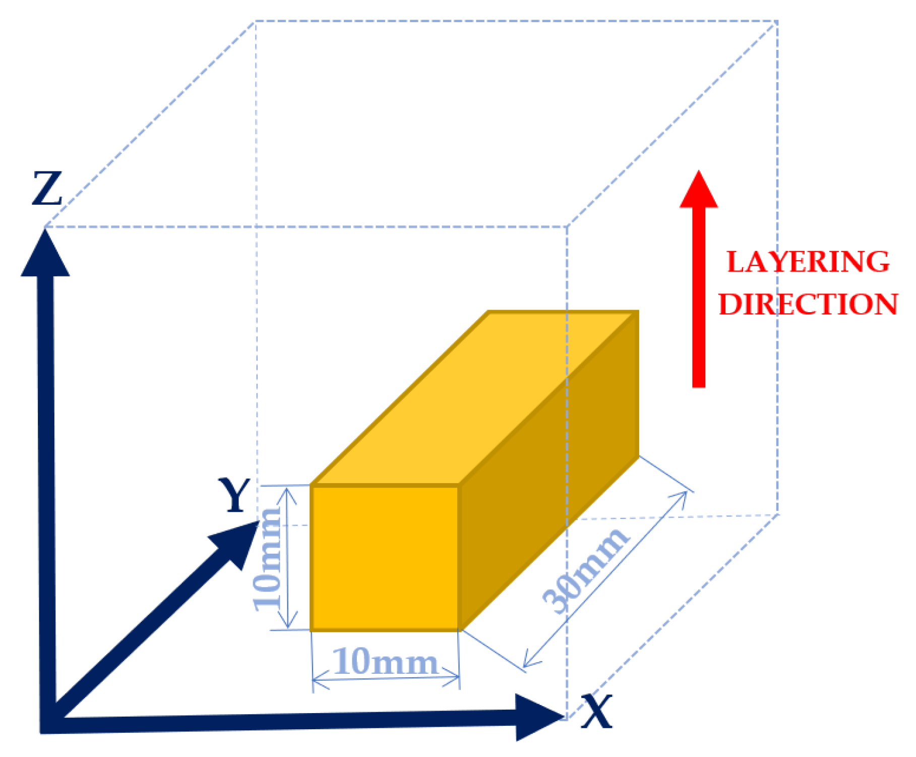
2.1. Experiment Preparation
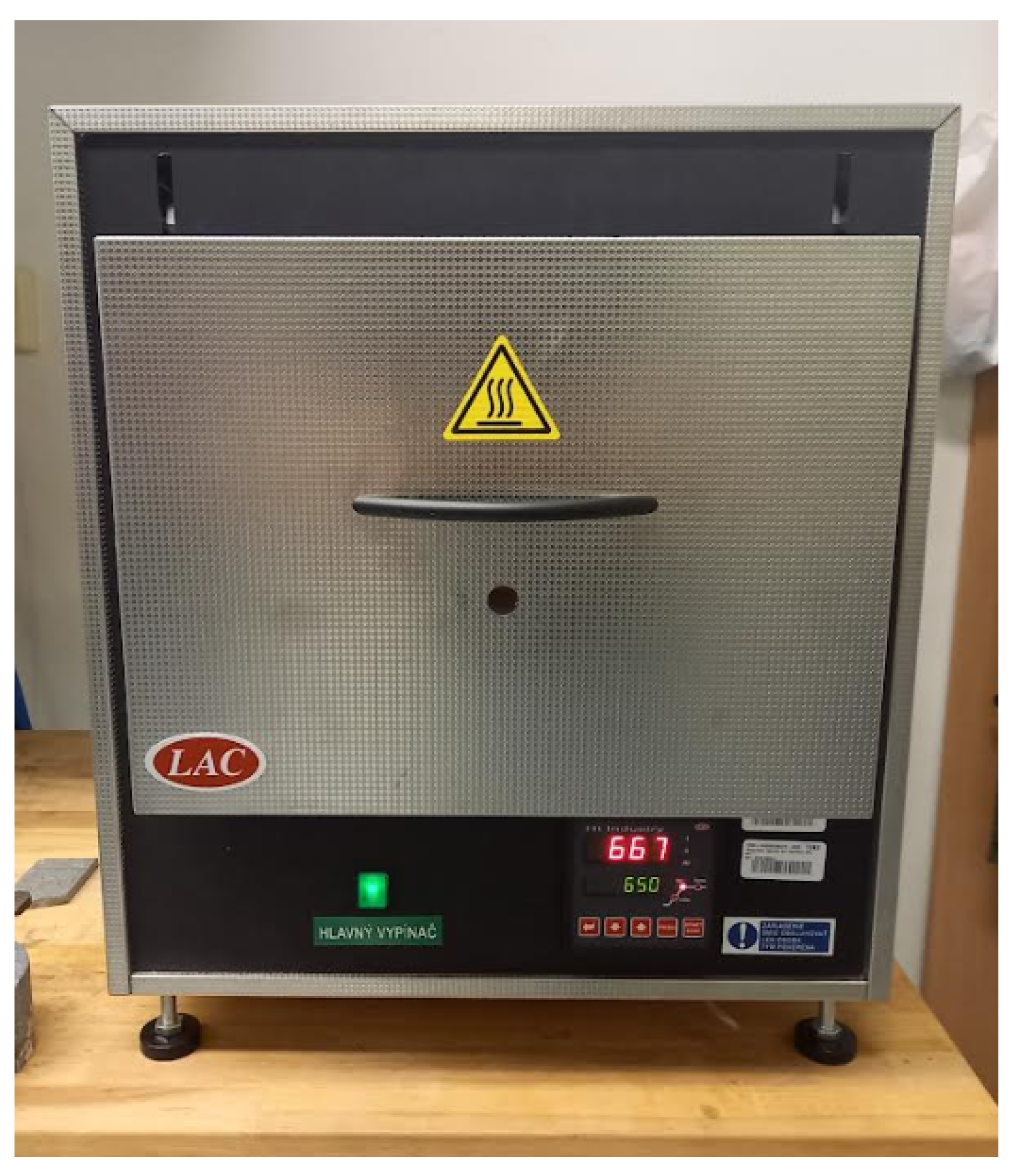
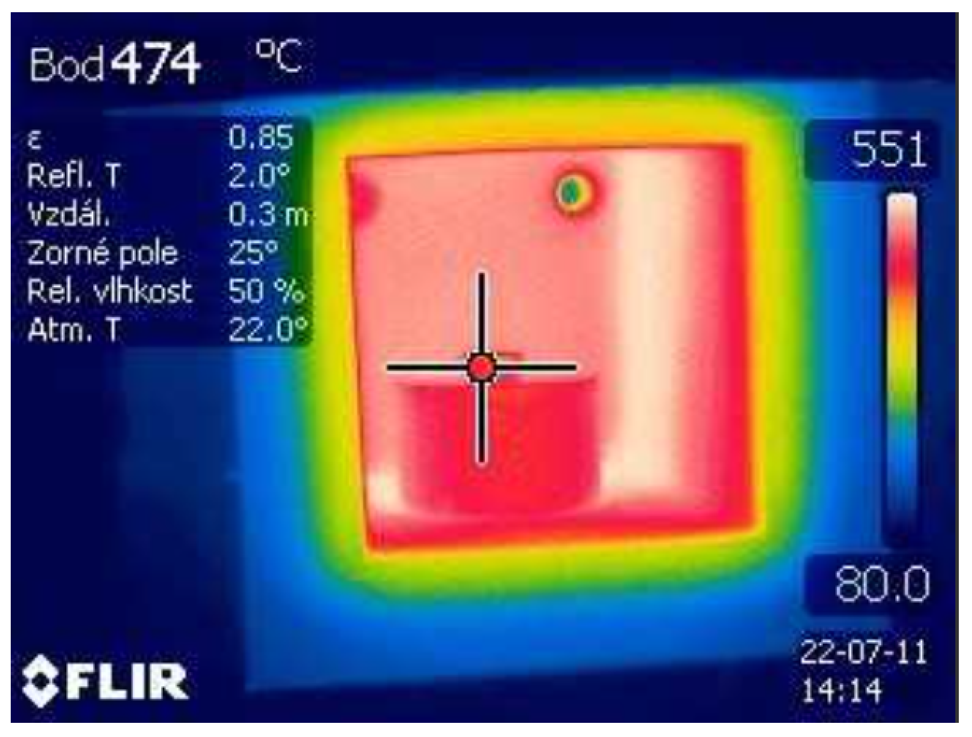
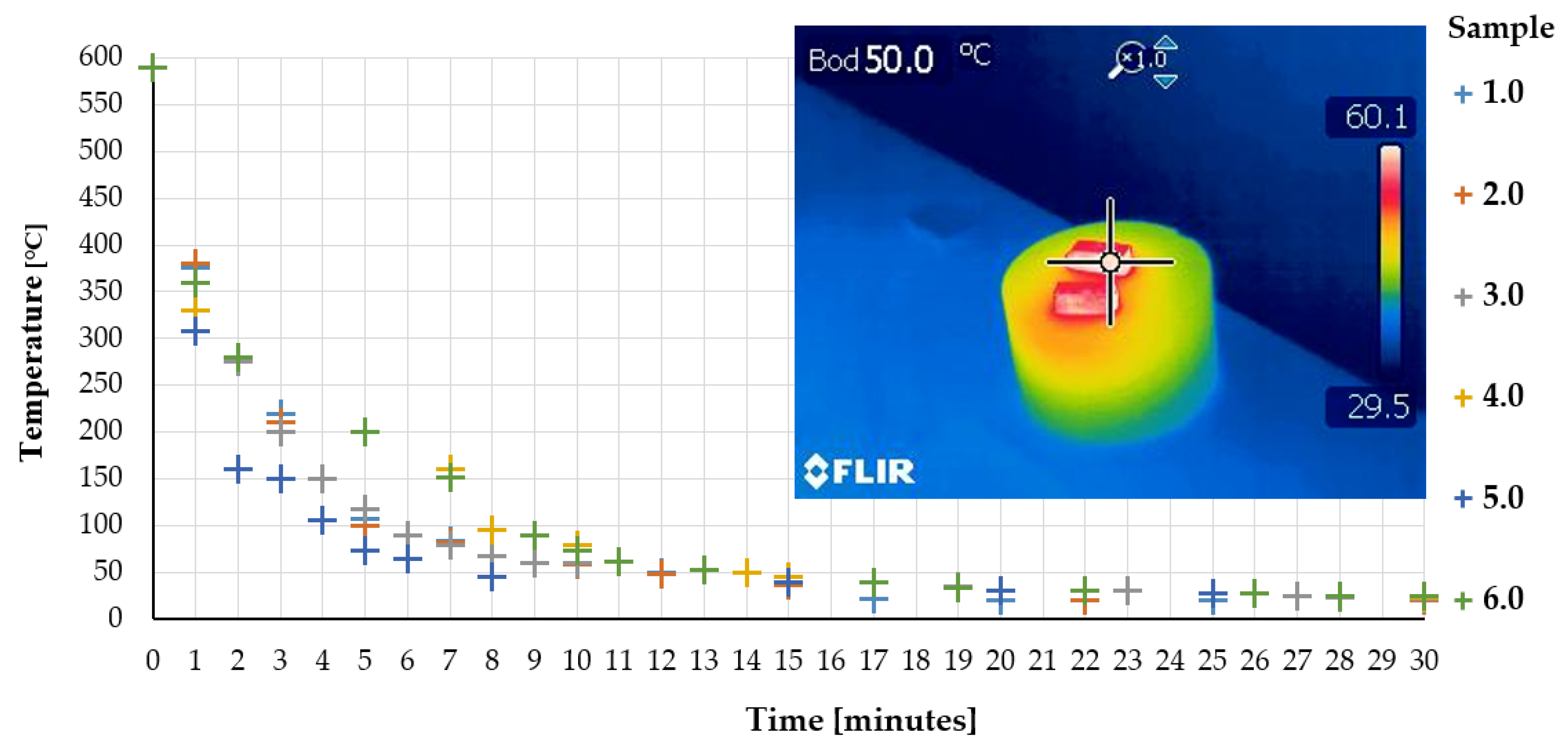
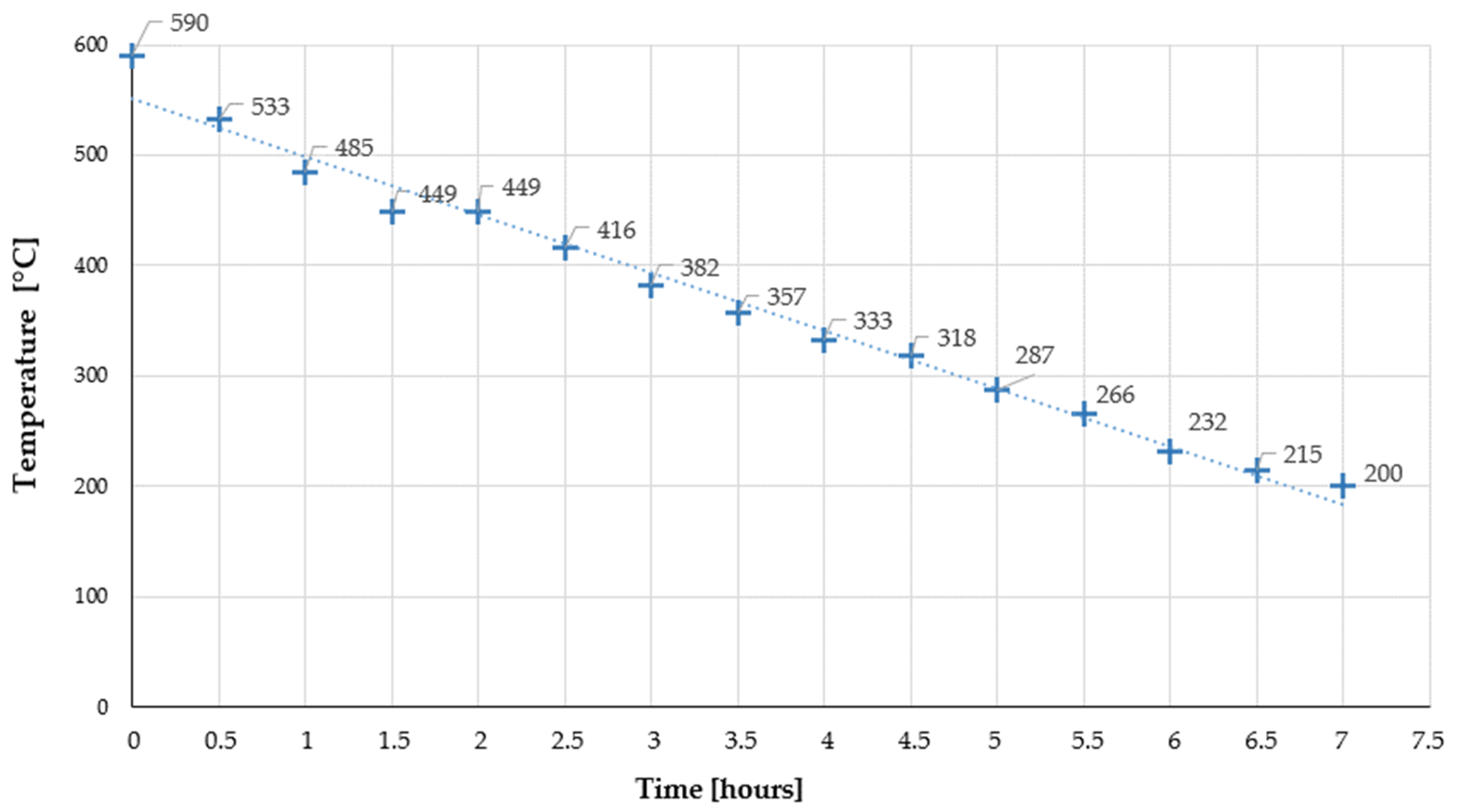
2.2. Process of Thermal Treatment
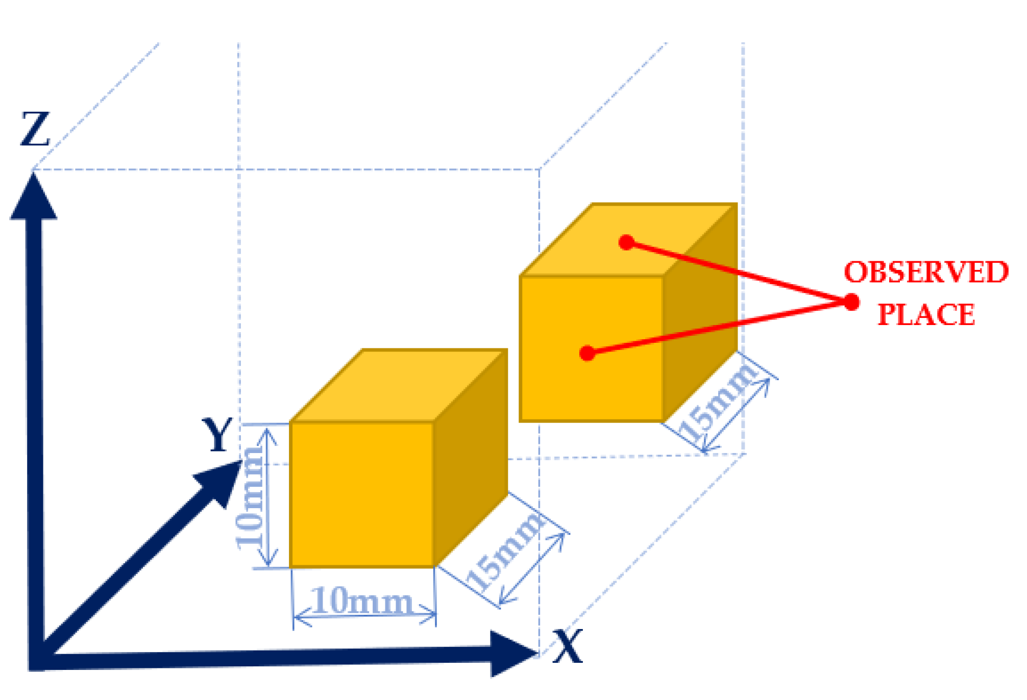
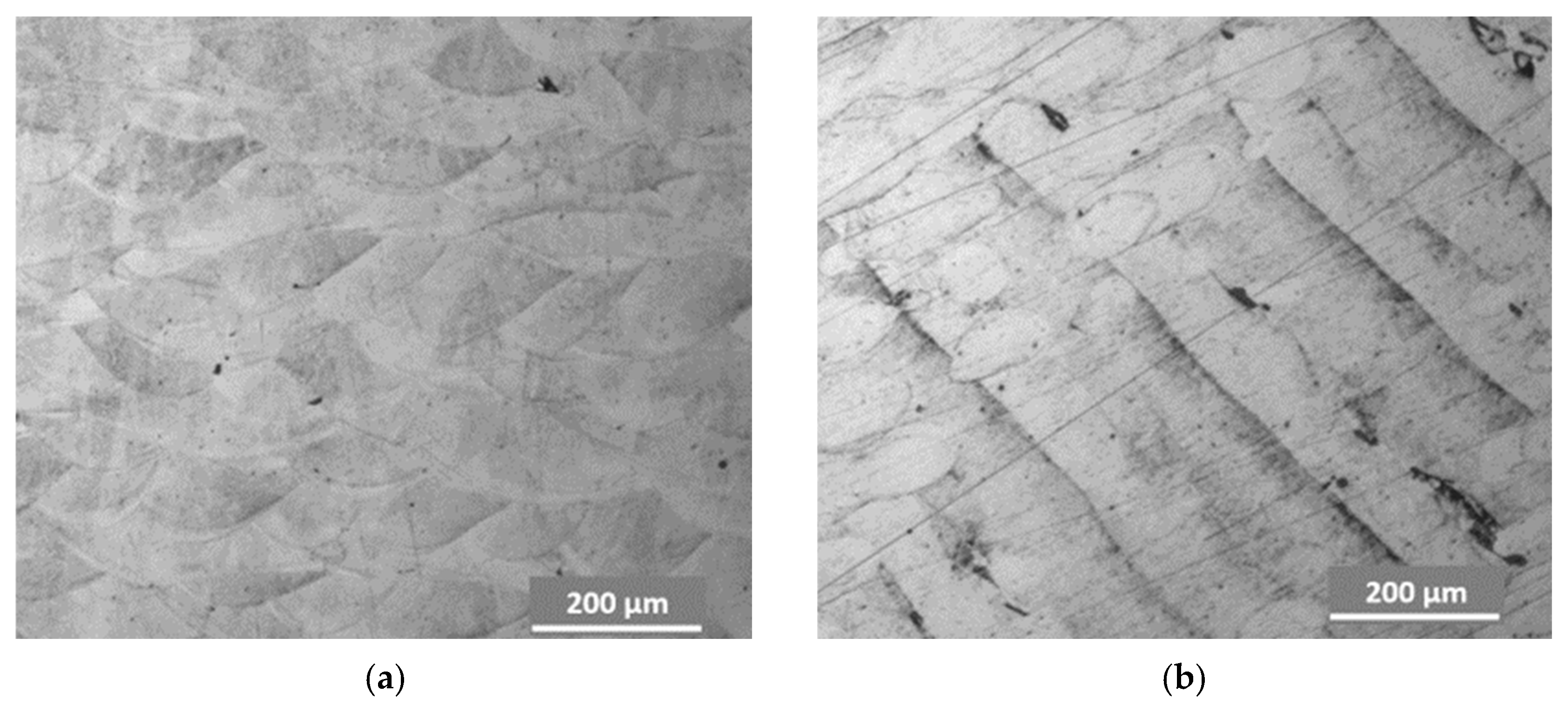
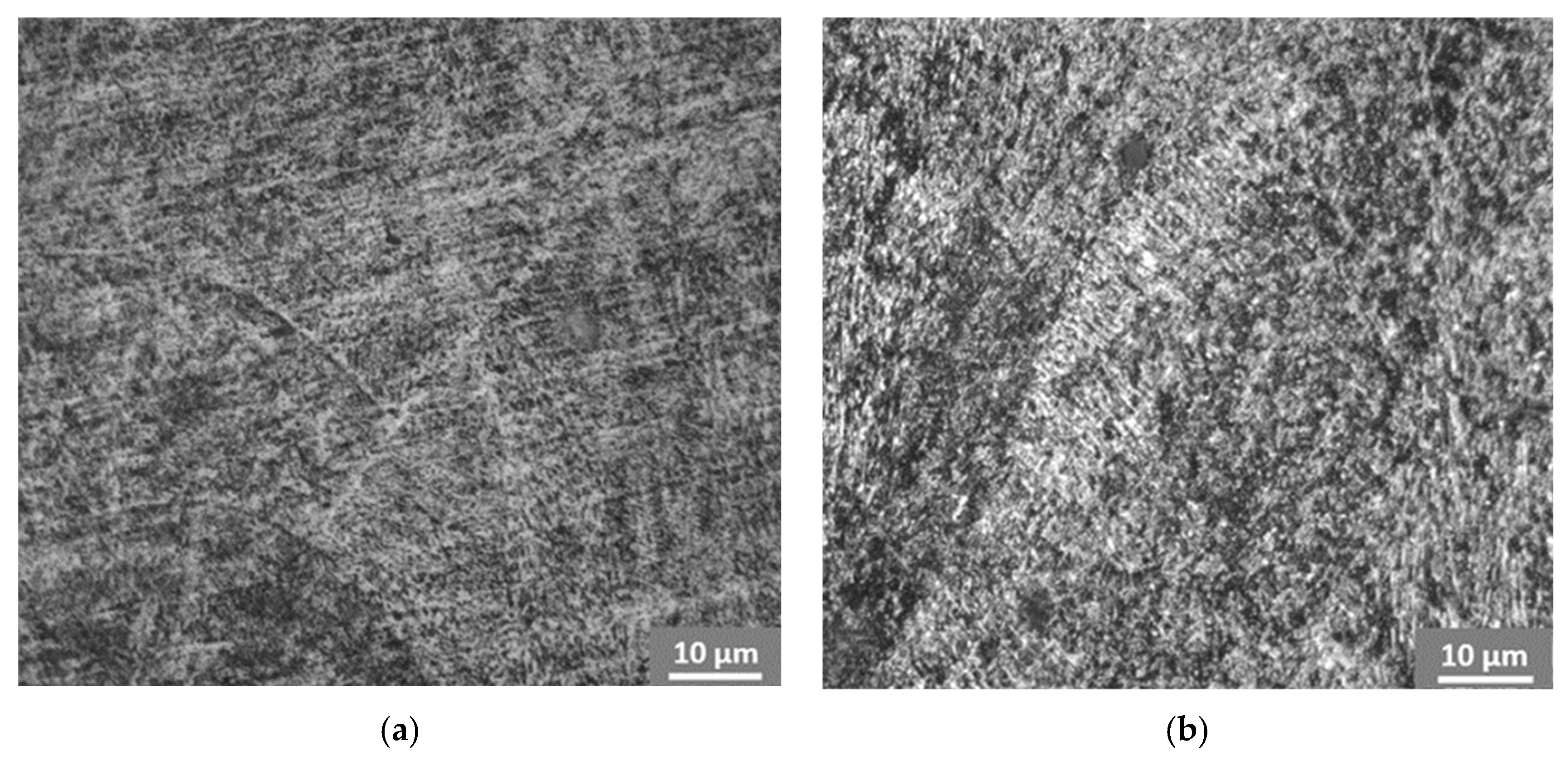
2.3. Preparation of Samples for Microstructure Observation and Hardness Evaluation
3. Results and Discussion
4. Conclusions
Author Contributions
Funding
Data Availability Statement
Acknowledgments
Conflicts of Interest
References
- Mançanares, C.G.; de S. Zancul, E.; Cavalcante da Silva, J.; Miguel, P.A.C. Additive manufacturing process selection based on parts selection criteria. Int. J. Adv. Manuf. Technol. 2015, 80, 1007–1014. [Google Scholar] [CrossRef]
- Yasa, E.; Kruth, J.-P. Microstructural investigation of selective laser melting 316L stainless steel parts exposed to laser re-melting. Procedia Eng. 2011, 19, 389–395. [Google Scholar] [CrossRef]
- Palermo, E. Laserové spekanie. Available online: https://www.livescience.com/38862-selective-laser-sintering.html (accessed on 8 August 2019).
- Dobránsky, J.; Kočiško, M.; Baron, P.; Simkulet, V.; Běhálek, L.; Vojnová, E.; Nováková-Marcinčínová, L’. Evaluation of the Impact Energy of the Samples Produced by the Additive Manufacturing Technology. Metalurgija 2016, 55, 477–480. [Google Scholar]
- Monková, K. Some Aspects of DMLS Technology; RISE Association: Houston, TX, USA, 2017; p. 117. ISBN 978-80-87670-23-1. [Google Scholar]
- Mower, T.M.; Long, M.J. Mechanical behavior of additive manufactured, powder-bed laser-fused materials. Mat. Sci. Eng. A 2016, 651, 198–213. [Google Scholar] [CrossRef]
- Brandl, E.; Leyens, C.; Palm, F.; Schoberth, A.; Onteniente, P. Wire instead of powder? Properties of additive manufactured Ti–6Al–4V for aerospace applications. In Proceedings of the Euro-uRapid International Conference on Rapid Prototyping, Rapid Tooling & Rapid Manufacturing, Berlin, Germany, 23–24 September 2008. [Google Scholar]
- Facchini, L.; Magalini, E.; Robotti, P.; Molinari, A.; Höges, S.; Wissenbach, K. Ductility of a Ti–6Al–4V alloy produced by selective laser melting of pre-alloyed powders. Rapid Prototyp. J. 2010, 16, 450–459. [Google Scholar] [CrossRef]
- Van Hooreweder, B.; Boonen, R.; Moens, D.; Kruth, J.-P.; Sas, P. On the determination of fatigue properties of Ti6Al4V produced by selective laser melting. In Proceedings of the 53rd AIAA/ASME Structures, Structural Dynamics and Materials Conference, Honolulu, HI, USA, 23–26 April 2012. [Google Scholar]
- Liu, Q.; Elambasseril, J.; Sun, S.; Leary, M.; Brandt, M.; Sharp, P.K. The effect of manufacturing defects on the fatigue behavior of Ti–6Al–4V specimens fabricated using selective laser melting. Adv. Mater. Res. 2014, 891–892, 1519–1524. [Google Scholar] [CrossRef]
- Radchenko, S.; Knapčíková, L.; Dupláková, D.; Hatala, M. Verifikácia mechanických vlastností kompozitných materiálov v klimakomore. Strojárstvo/Strojírenství. Roč. 2016, 10, 82. (accessed on 1 October 2016). [Google Scholar]
- Shellabear, M.; Nyrhilä, O. DMLS—Development History and State of the Art. Available online: https://www.i3dmfg.com/wp-content/uploads/2015/07/History-of-DMLS.pdf (accessed on 15 December 2022).
- Ciraud, P. Verfahren und Vorrichtung zur Herstellung beliebiger Gegenstände aus beliebigem schmelzbarem Material. German Patent Application DE 2263777, 28 December 1971. [Google Scholar]
- Housholder, R. Molding Process. US Patent 4,247,508, 3 December 1979. [Google Scholar]
- Metal Additive Manufacturing History. Available online: https://additive-manufacturing-report.com/technology/metal/metal-additive-manufacturing-history/ (accessed on 15 November 2019).
- Hull, C. Method and Apparatus for Production of Three-Dimensional Objects by Stereolithography. US Patent 4,575,330, 8 August 1984. [Google Scholar]
- Deckard, C. Method and Apparatus for Producing Parts by Selective Sintering. US Patent 4,863,538, 17 October 1986. [Google Scholar]
- Nyrhilä, O.; Syrjälä, S. Manufacture of dimensionally precise pieces by sintering. Finnish Patent Finnish Patent 91725, 7 April 1989. [Google Scholar]
- Gašpár, Š.; Paško, J. Analysis of influence of pressing speed, of melt temperature and of casting position in a mold upon ultimate tensile strength Rm of die casting from aluminium. In Advanced Materials Research: 2nd International Conference on Manufacturing 2014, Singapore, 9–10 February 2014; Springer: Berlin/Heidelberg, Germany, 2014; Volume 909, pp. 3–7. ISBN 978-303835059-0. ISSN 1022-6680. [Google Scholar]
- Simkulet, V.; Gusak, O.; Zajac, J.; Parilák, L’.; Mitaľová, Z. Verifikácia procesu tepelného spracovania materiálu vyrobeného technológiou priameho spekania laserom. In Automatizácia a riadenie v teórii a praxi: ARTEP 2018; Technical University of Košice: Košice, Slovakia, 2018; pp. 1–7. ISBN 978-80-553-2914-7. [Google Scholar]
- Monkova, K.; Monka, P.; Mandulak, D. Hardness and Surface Roughness Study of Steel Part Produced by Additive Technology. DEStech Trans. Eng. Technol. Res 2017. [Google Scholar] [CrossRef] [PubMed] [Green Version]
- Yu, N. Process Parameter Optimization for Direct Metal Laser Sintering (DMLS). Ph.D. Thesis, National University of Singapore, Singapore, 2005. [Google Scholar]
- Maharjan, N.; Wu, N.; Zhou, W. Hardening Efficiency and Microstructural Changes during Laser Surface Hardening of 50CrMo4 Steel. Metals 2021, 11, 2015. [Google Scholar] [CrossRef]
- Kučerová, L.; Zetková, I.; Jeníček, Š.; Burdová, K. Production of Hybrid Joints by Selective Laser Melting of Maraging Tool Steel 1.2709 on Conventionally Produced Parts of the Same Steel. Materials 2021, 14, 2105. [Google Scholar] [CrossRef] [PubMed]
- Sarafan, S.; Wanjara, P.; Gholipour, J.; Bernier, F.; Osman, M.; Sikan, F.; Molavi-Zarandi, M.; Soost, J.; Brochu, M. Evaluation of Maraging Steel Produced Using Hybrid Additive/Subtractive Manufacturing. J. Manuf. Mater. Process. 2021, 5, 107. [Google Scholar] [CrossRef]
- Wang, X.; Chou, K. Effect of support structures on Ti-6Al-4V overhang parts fabricated by powder bed fusion electron beam additivemanufacturing. J. Mater. Process. Technol. 2018, 257, 65–78. [Google Scholar] [CrossRef]
- Gåård, A.; Krakhmalev, P.; Bergström, J. Microstructural characterization and wear behavior of (Fe,Ni)–TiC MMC prepared by DMLS. J. Alloys Compd. 2006, 421, 166–171. [Google Scholar] [CrossRef]
- Živčák, J.; Nováková-Marcinčínová, E.; Nováková-Marcinčínová, Ľ.; Balint, T.; Puškár, M. Increasing Mechanical Properties of 3D Printed Samples by Direct Metal Laser Sintering Using Heat Treatment Process. J. Mar. Sci. Eng. 2021, 9, 821. [Google Scholar] [CrossRef]
- Zhao, Z.-Y.; Li, L.; Bai, P.-K.; Jin, Y.; Wu, L.-Y.; Li, J.; Guan, R.-G.; Qu, H.-Q. The Heat Treatment Influence on the Microstructure and Hardness of TC4 Titanium Alloy Manufactured via Selective Laser Melting. Materials 2018, 11, 1318. [Google Scholar] [CrossRef] [PubMed] [Green Version]
- Avanzini, A.; Battini, D.; Gelfi, M.; Girelli, L.; Petrogalli, C.; Pola, A.; Tocci, M. Investigation on fatigue strength of sand-blasted DMLS-AlSi10Mg alloy. Procedia Struct. Integr. 2019, 18, 119–128. [Google Scholar] [CrossRef]
- Rafi, H.K.; Starr, T.L.; Stucker, B.E. A comparison of the tensile, fatigue and fracture behavior of Ti–6Al–4V and 15–5 PH stainless steel parts made by selective laser melting. Int. J. Manuf. Technol. 2013, 69, 1299–1309. [Google Scholar] [CrossRef]
- Simm, T.H.; Sun, L.; Galvin, D.R.; Hill, P.; Rawson, M.; Birosca, S.; Gilbert, E.P.; Bhadeshia, H.; Perkins, K. The effect of a two-stage heat-treatment on the microstructural and mechanical properties of a maraging steel. Materials 2017, 10, 1346. [Google Scholar] [CrossRef] [PubMed] [Green Version]
- Shamantha, C.R.; Narayanan, R.; Iyer, K.J.L.; Radhakrishnan, V.M.; Seshadri, S.K.; Sundararajan, S.; Sundaresan, S. Microstructural changes during welding and subsequent heat treatment of 18Ni (250-grade) maraging steel. Mater. Sci. Eng. A 2000, 287, 43–51. [Google Scholar] [CrossRef]
- N’Dri, N.; Mindt, H.W.; Shula, B.; Megahed, M.; Peralta, A.; Kantzos, P.; Neumann, J. DMLS Process Modeling and Validation. In Proceedings of the TMS 2015 144th Annual Meeting & Exhibition, Orlando, FL, USA, 15–19 March 2015; pp. 389–396. [Google Scholar]
- Sun, S.; Brandt, M.; Easton, M. Powder bed fusion processes: An overview. In Laser Additive Manufacturing: Materials, Design, Technologies, and Applications; Woodhead Publishing Series in Electronic and Optical Materials; Elsevier: Amsterdam, The Netherlands, 2017; pp. 55–77. [Google Scholar]
- About Additive Manufacturing. Available online: https://www.lboro.ac.uk/research/amrg/about/the7categoriesofadditivemanufacturing/powderbedfusion/ (accessed on 22 December 2022).
- Edwards, P.; Ramulu, M. Fatigue performance of selective laser melted Ti–6Al–4V. Mater. Sci. Eng. A 2014, 598, 327–337. [Google Scholar] [CrossRef]
- Available online: https://www.scribd.com/document/479137808/EOS-MaragingSteel-MS1-en-pdf# (accessed on 15 September 2022).
- Available online: https://www.advancedtek.com/wp-content/uploads/2021/09/EOS_materials_table_overview_M_en_WEB.pdf (accessed on 15 December 2022).
- Lebar, A.; Junkar, M. Simulation of abrasive waterjet machining based on unit event features. Proc. Inst. Mech. Eng. Part B J. Eng. Manuf. 2003, 217, 699–703. [Google Scholar] [CrossRef]


| Sample | Heat Treatment | ||
|---|---|---|---|
| Duration Time (Hours) | Curing Temperature (°C) | Cooling | |
| 1.0 | 1 | 590 | in the still air |
| 2.0 | 2 | 590 | in the still air |
| 2.1 | 2 | 590 | in furnace |
| 3.0 | 3 | 590 | in the still air |
| 4.0 | 4 | 590 | in the still air |
| 5.0 | 5 | 590 | in the still air |
| 6.0 | 6 | 590 | in the still air |
| 6.1 | 6 | 590 | in furnace |
| Element * | Al | Ti | Mn, Si | Cr, Cu | Mo | Co | Ni |
|---|---|---|---|---|---|---|---|
| Mass (%) | 0.05 | 0.6 | up | up | 4.5 | 8.5 | 17 |
| – | – | to | to | – | – | – | |
| 0.15 | 0.8 | 0.1 | 0.5 | 5.2 | 9.5 | 19 |
| Density ρ, (g/cm3) | Tensile Strength (MPa) | Yield Strength Rp0.2, (%) | Elongation at Break, % | Modulus of Elasticity, (GPa) | Hardness (HRC) * | |
|---|---|---|---|---|---|---|
| direction | XY | XY | XY | XY | 33–37 | |
| 8.0–8.1 | (a) | 1000–1200 | 1950–1150 | 6–14 | 135–185 | |
| direction | Z | Z | Z | Z | ||
| 8.0–8.1 | (a) | 1000–1200 | 1850–1150 | - | 130–170 | |
| (b) | 1950–2150 | 1090–1290 | 2–6 | 50–56 |
| As Built | Hardened * | |
|---|---|---|
| Thermal conductivity | 14.2–15.8 W/m °C | 19–21 W/m °C |
| Specific heat capacity | 430–470 J/kg °C | |
| Operating temp. | max. 400 °C | |
| Sample | Measuring Side, Hardness Value | Average Hardness Value | |||
|---|---|---|---|---|---|
| x-y(Bottom) | x-y(Top) | y-z(Right Side) | y-z(Left Side) | ||
| 0.0 * | 36.7 | 36.7 | |||
| 1.0 | 29.6 | 50.4 | 47.8 | 47.9 | 43.9 |
| 2.0 | 27.1 | 48.1 | 36.7 | 45.2 | 39.3 |
| 2.1 ** | 35.1 | 45.9 | 37.9 | 48.8 | 41.9 |
| 3.0 | 40.5 | 37.9 | 42.4 | 41.1 | 40.5 |
| 4.0 | 25.1 | 37.3 | 46.4 | 45.7 | 38.6 |
| 5.0 | 32.5 | 46.3 | 37.5 | 47 | 40.8 |
| 6.0 | 37 | 51.3 | 42.7 | 45.8 | 44.2 |
| 6.1 ** | 21.9 | 42.7 | 49.8 | 46.8 | 40.3 |
| Sample | Measuring Side, Hardness Value | Average Hardness Value | Measurement in the Center | |||
|---|---|---|---|---|---|---|
| x-z (Bottom) | x-z (Top) | x-z (Right Side) | x-z (Left Side) | |||
| 1.0 | 49.7 | 50.2 | 51 | 50.7 | 50.4 | 51 |
| 2.0 | 48.9 | 48.2 | 49.1 | 43.4 | 47.4 | 49.2 |
| 2.1 ** | 49.4 | 49.9 | 50.2 | 49.5 | 49.8 | 49.5 |
| 3.0 | 49.2 | 46.5 | 48.6 | 48.1 | 48.1 | 49.5 |
| 4.0 | 48 | 45.2 | 47.7 | 46.9 | 47 | 47.7 |
| 5.0 | 44.1 | 46 | 45.9 | 45.4 | 45.4 | 46.9 |
| 6.0 | 46.8 | 47.5 | 46.8 | 45.4 | 46.6 | 47.5 |
| 6.1 ** | 47 | 46.7 | 46 | 46 | 46.4 | 46.8 |
Disclaimer/Publisher’s Note: The statements, opinions and data contained in all publications are solely those of the individual author(s) and contributor(s) and not of MDPI and/or the editor(s). MDPI and/or the editor(s) disclaim responsibility for any injury to people or property resulting from any ideas, methods, instructions or products referred to in the content. |
© 2023 by the authors. Licensee MDPI, Basel, Switzerland. This article is an open access article distributed under the terms and conditions of the Creative Commons Attribution (CC BY) license (https://creativecommons.org/licenses/by/4.0/).
Share and Cite
Vandzura, R.; Simkulet, V.; Gelatko, M.; Hatala, M.; Mitalova, Z. Effect of Hardening Temperature on Maraging Steel Samples Prepared by Direct Metal Laser Sintering Process. Machines 2023, 11, 351. https://doi.org/10.3390/machines11030351
Vandzura R, Simkulet V, Gelatko M, Hatala M, Mitalova Z. Effect of Hardening Temperature on Maraging Steel Samples Prepared by Direct Metal Laser Sintering Process. Machines. 2023; 11(3):351. https://doi.org/10.3390/machines11030351
Chicago/Turabian StyleVandzura, Radoslav, Vladimir Simkulet, Matus Gelatko, Michal Hatala, and Zuzana Mitalova. 2023. "Effect of Hardening Temperature on Maraging Steel Samples Prepared by Direct Metal Laser Sintering Process" Machines 11, no. 3: 351. https://doi.org/10.3390/machines11030351