
Design to Reduce Cogging Torque and Irreversible Demagnetization in Traction Hybrid Motor Using Dy-free Magnet


Abstract
:1. Introduction
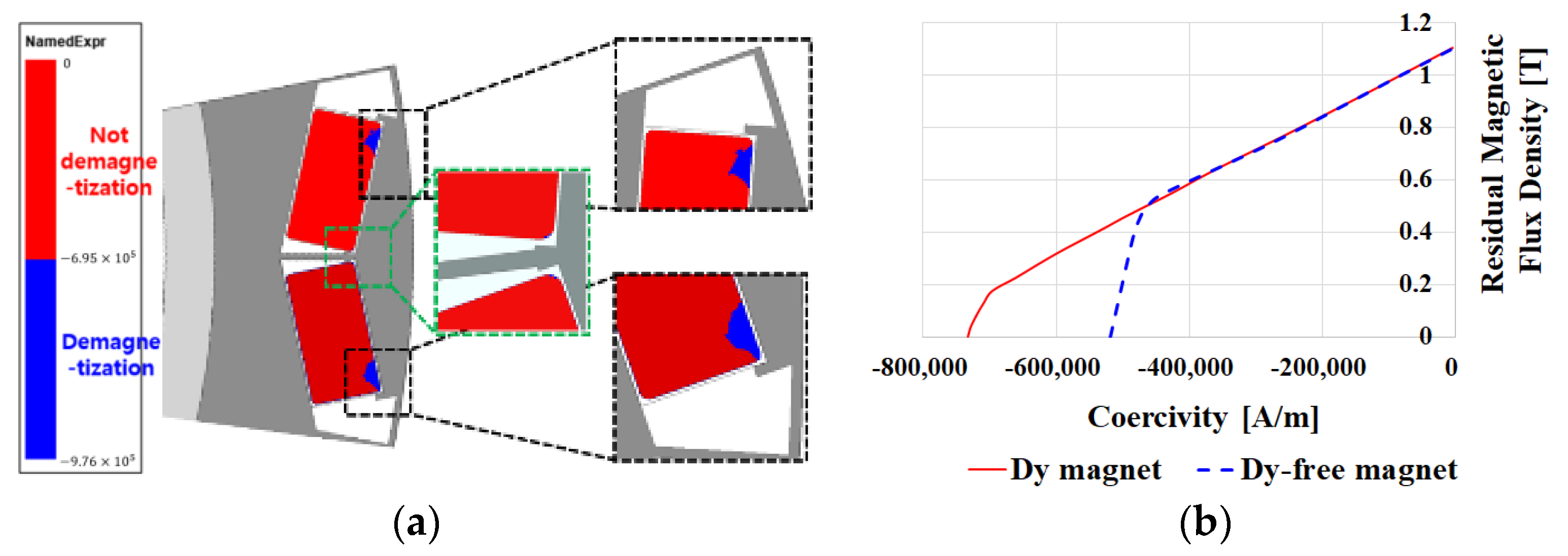
2. Conventional Model Analysis
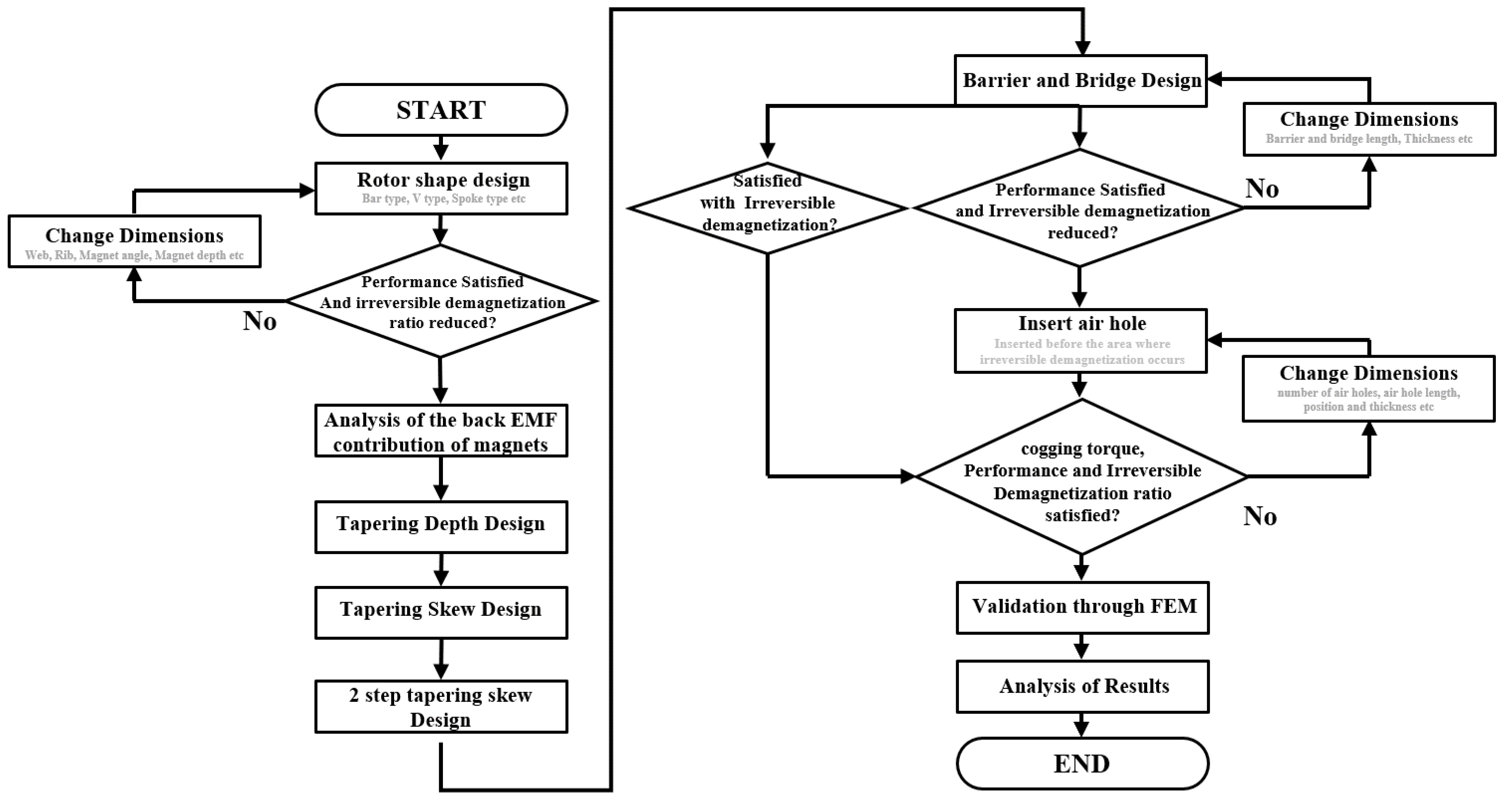
3. A Study on Reducing Cogging Torque and Irreversible Demagnetization through the Application of a Tapering Structure
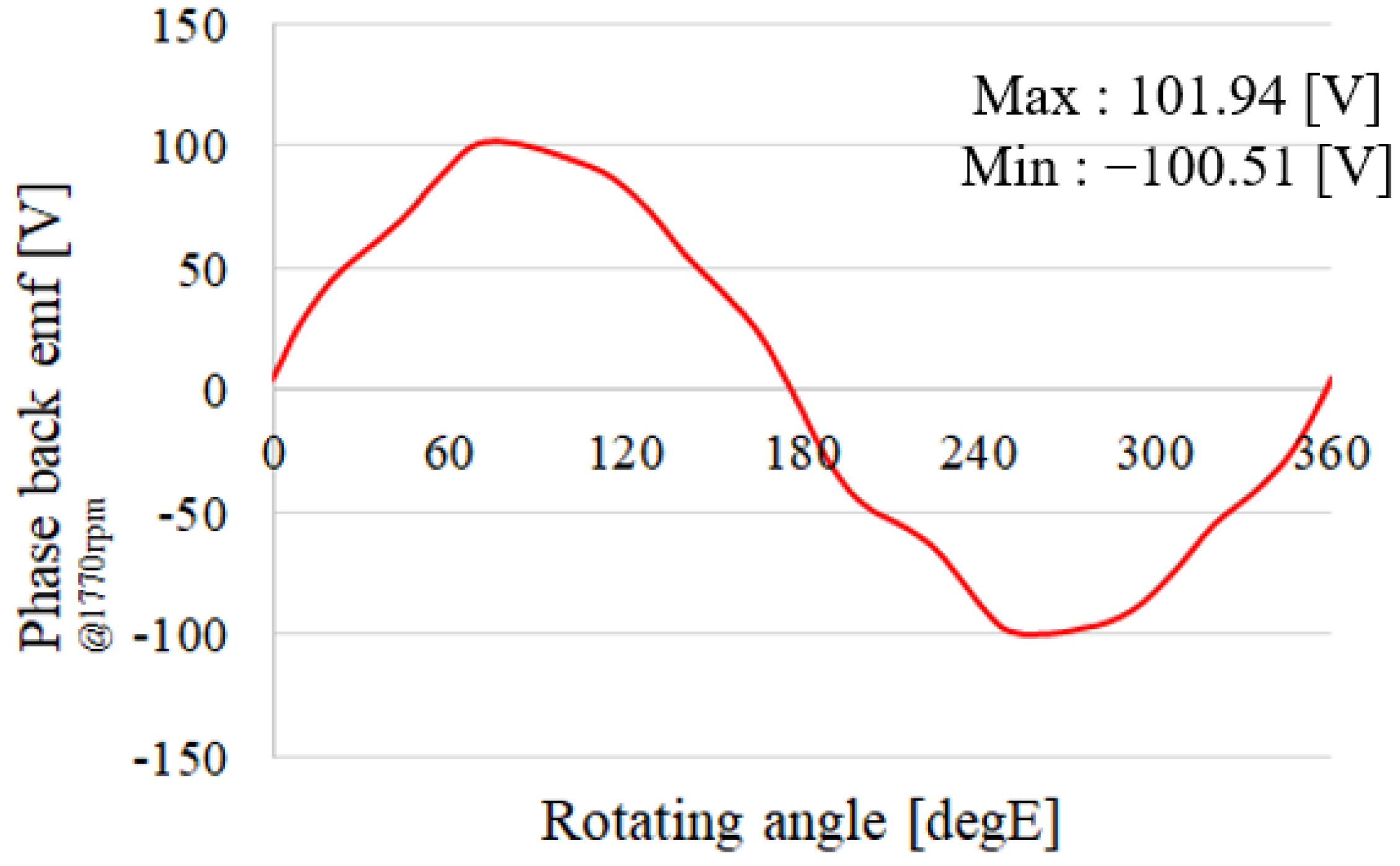
3.1. Application of Tapering Structure
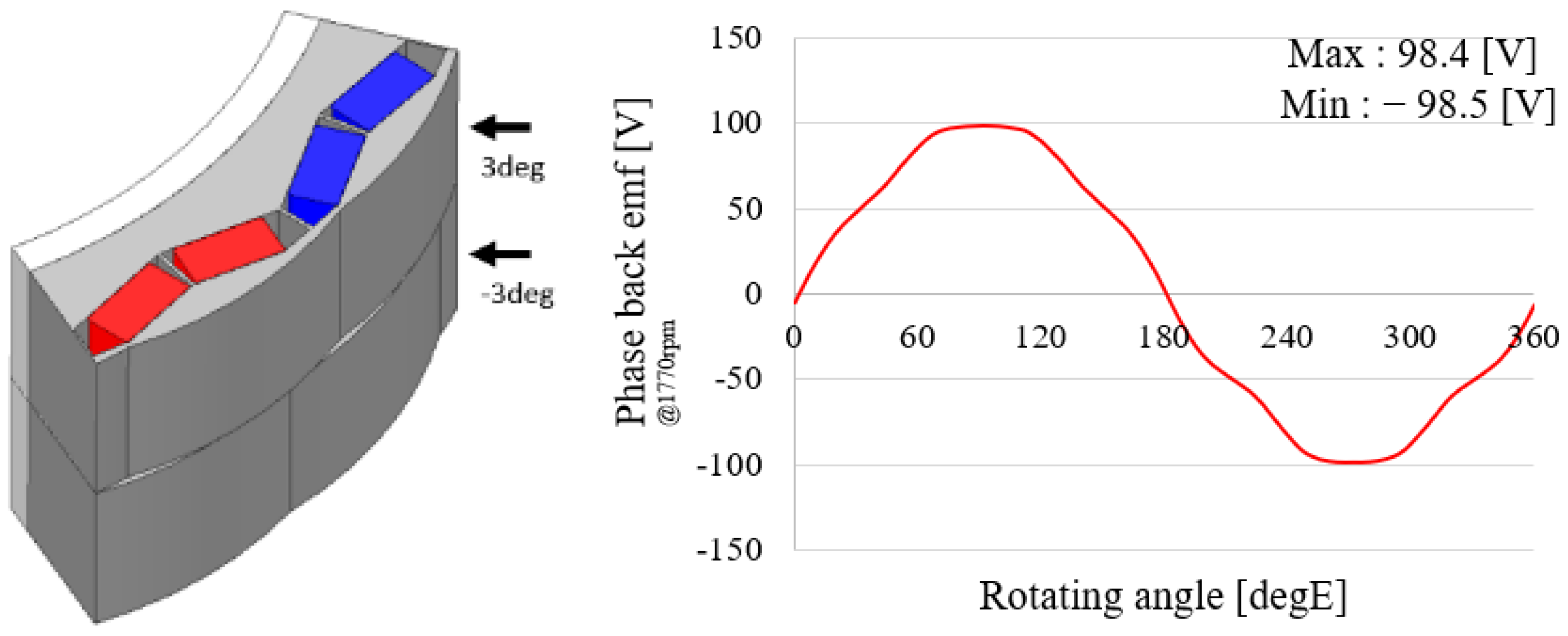
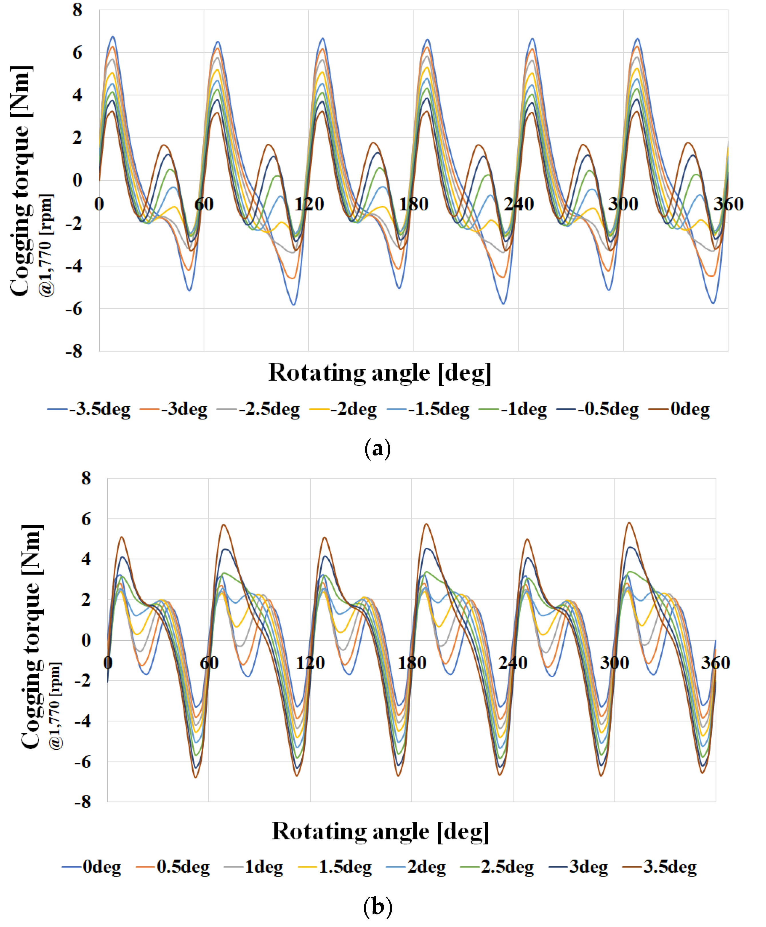
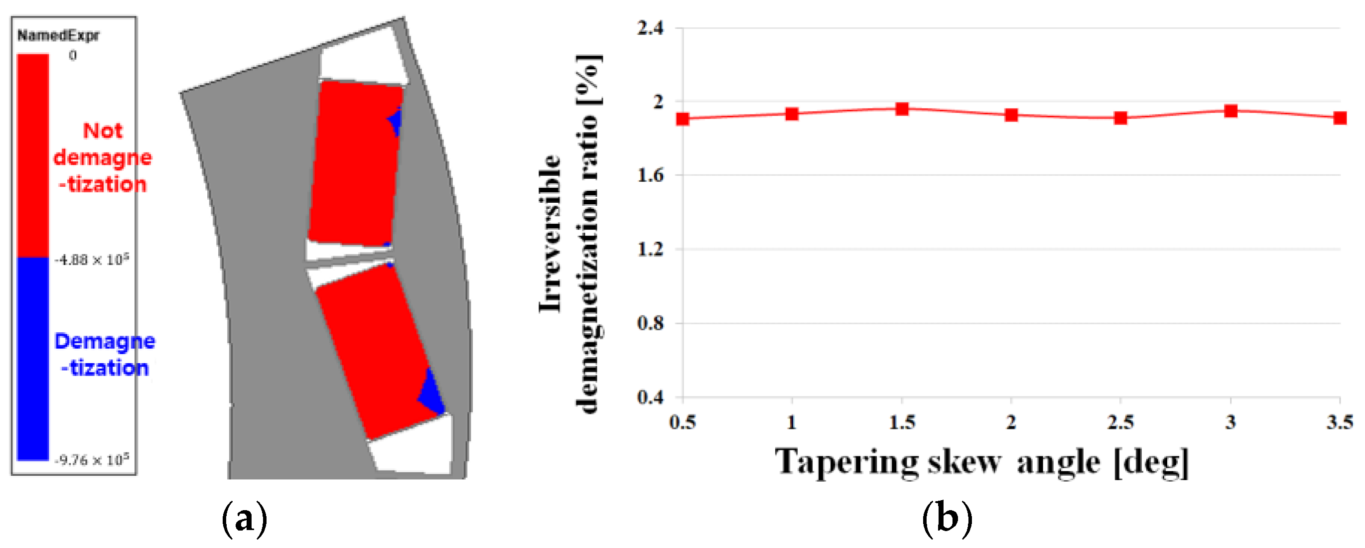
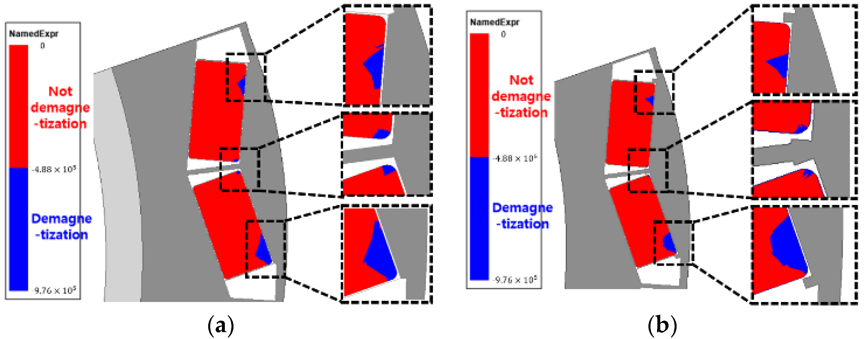
3.2. Application of Tapering skew Structure
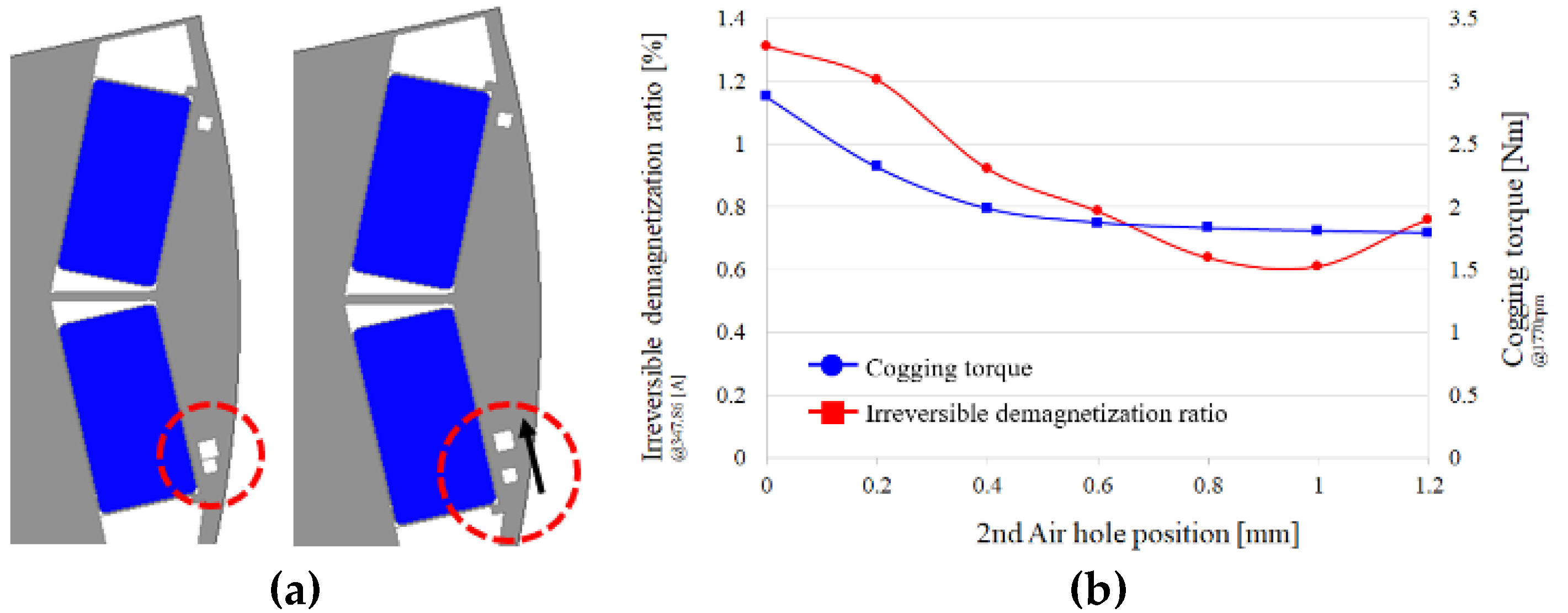
4. Research on Irreversible Demagnetization Ratio and Cogging Torque Reduction through Asymmetric Air Hole Insertion
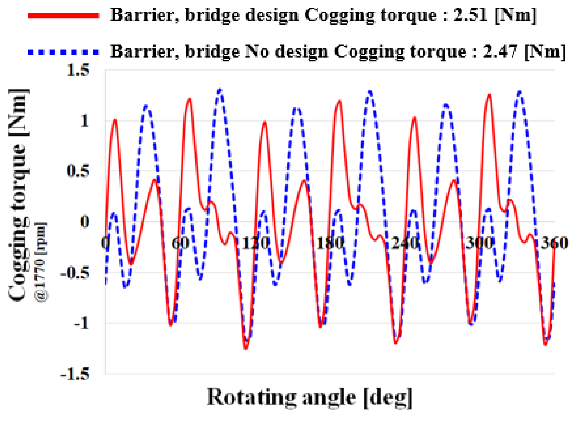
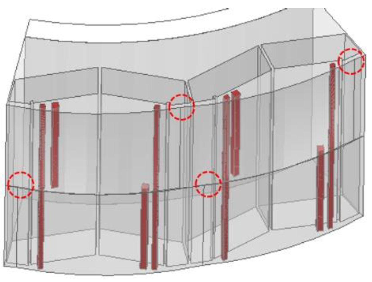
4.1. Bridge and Barrier Support Structure Design
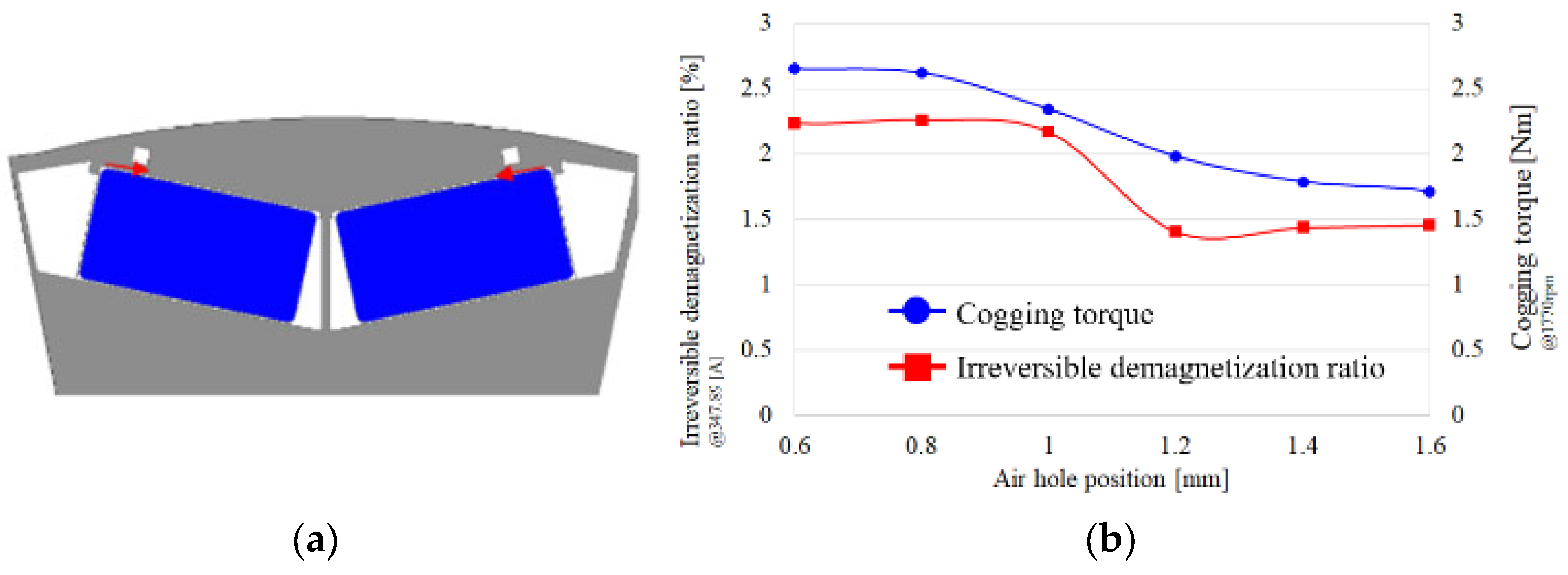
4.2. Insertion of Air Hole
5. Electromagnetic and Mechanical Performance Analysis
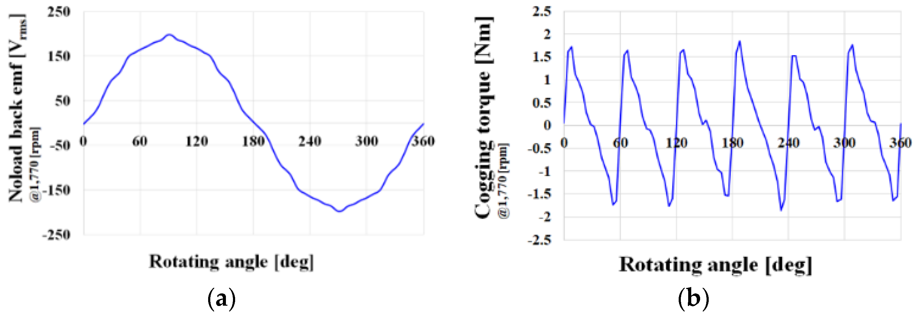
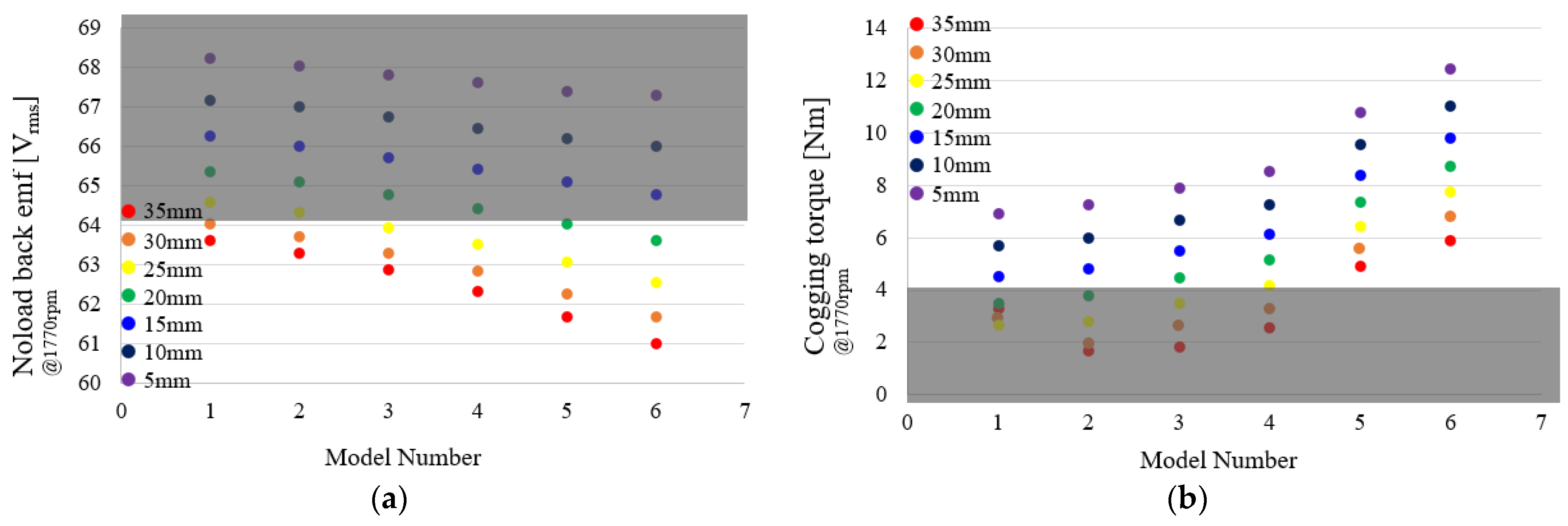
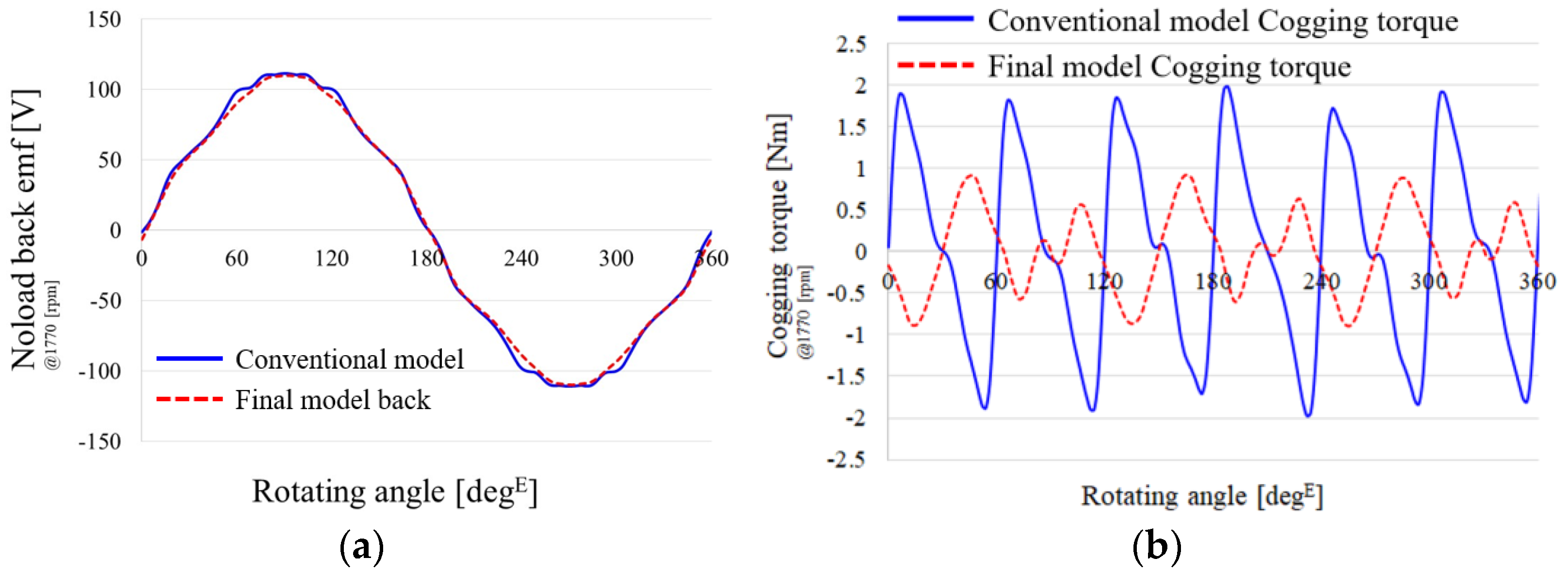
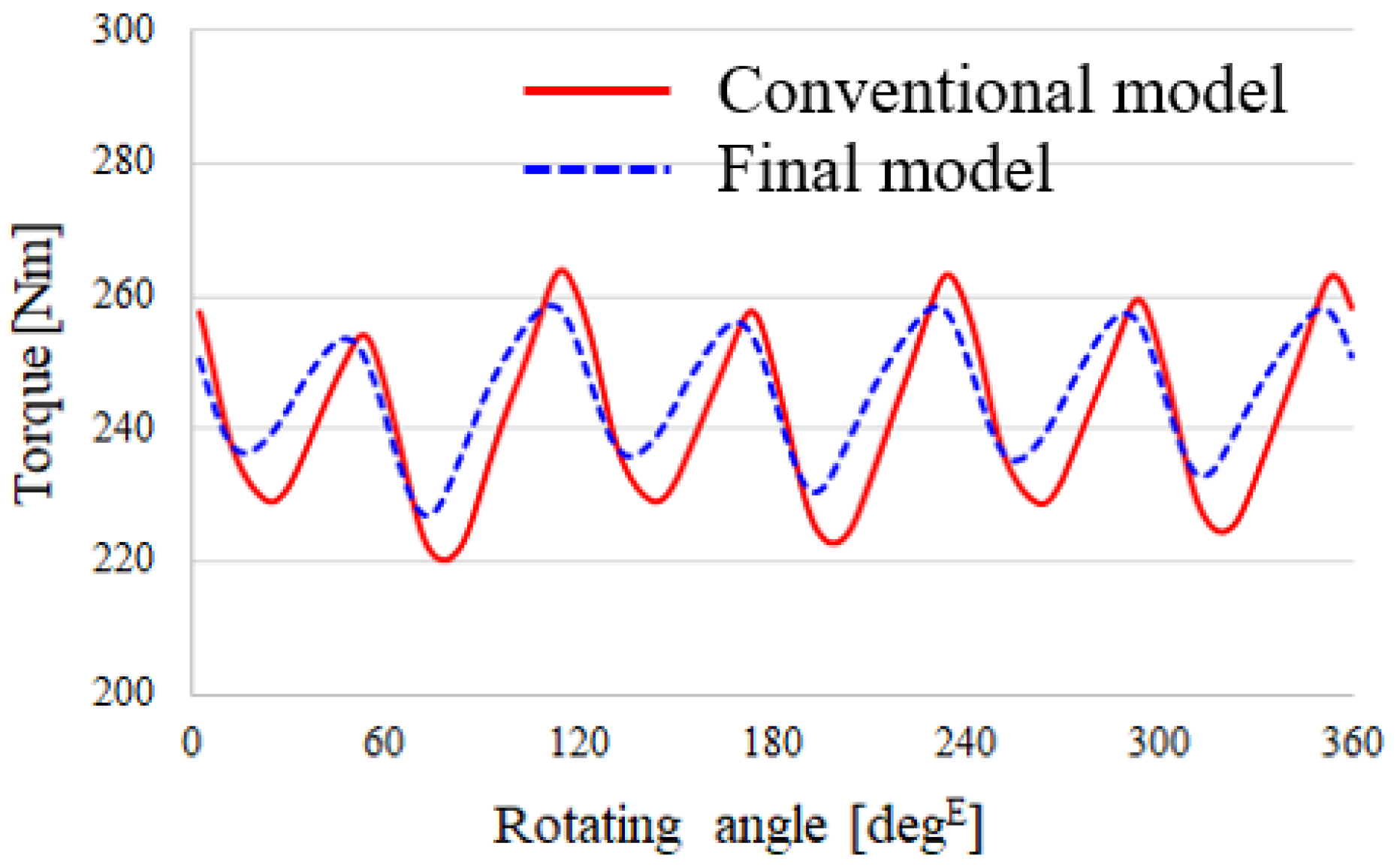
5.1. Electromagnetic Performance Analysis
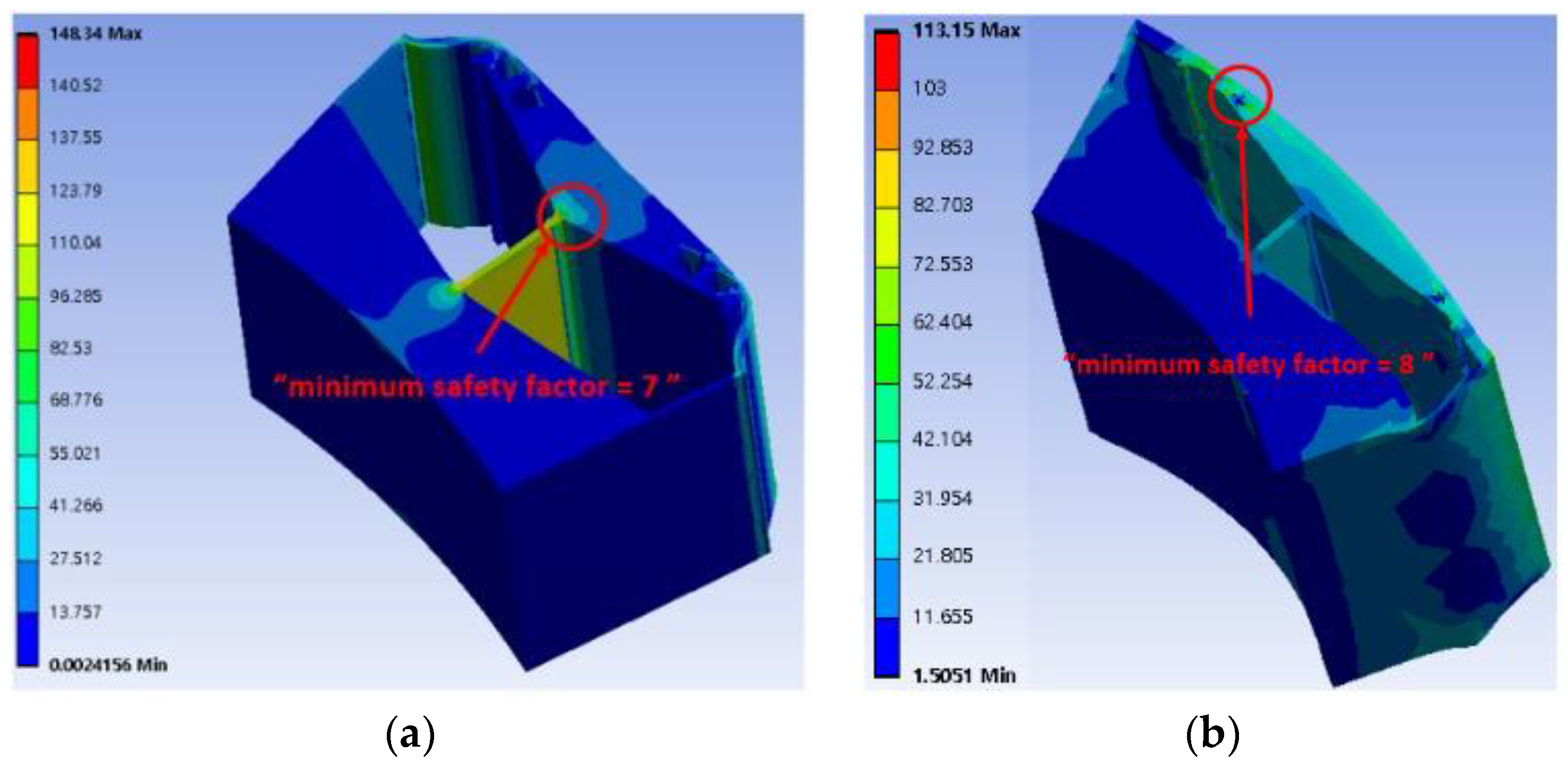
5.2. Mechanical Performance Analysis
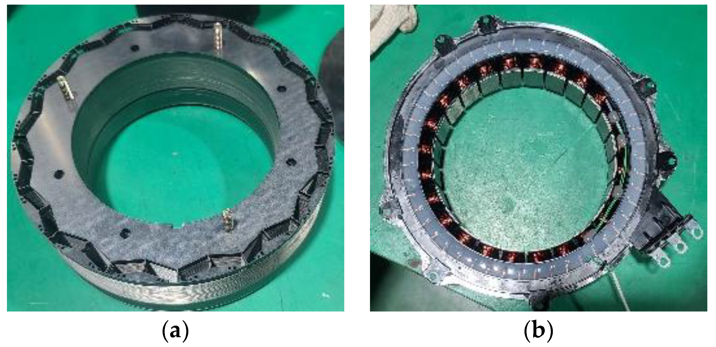
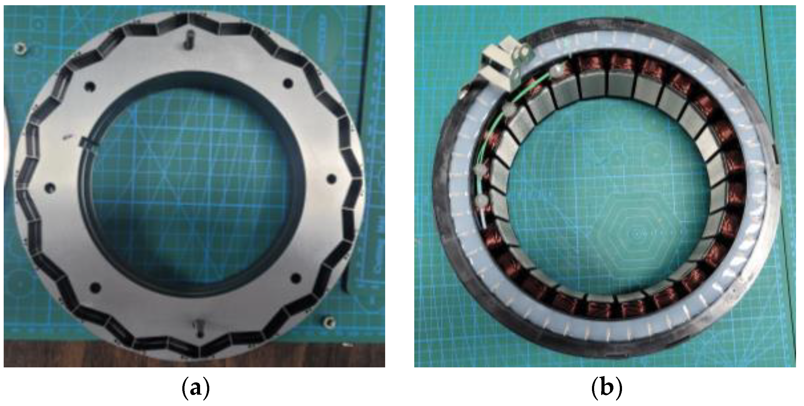
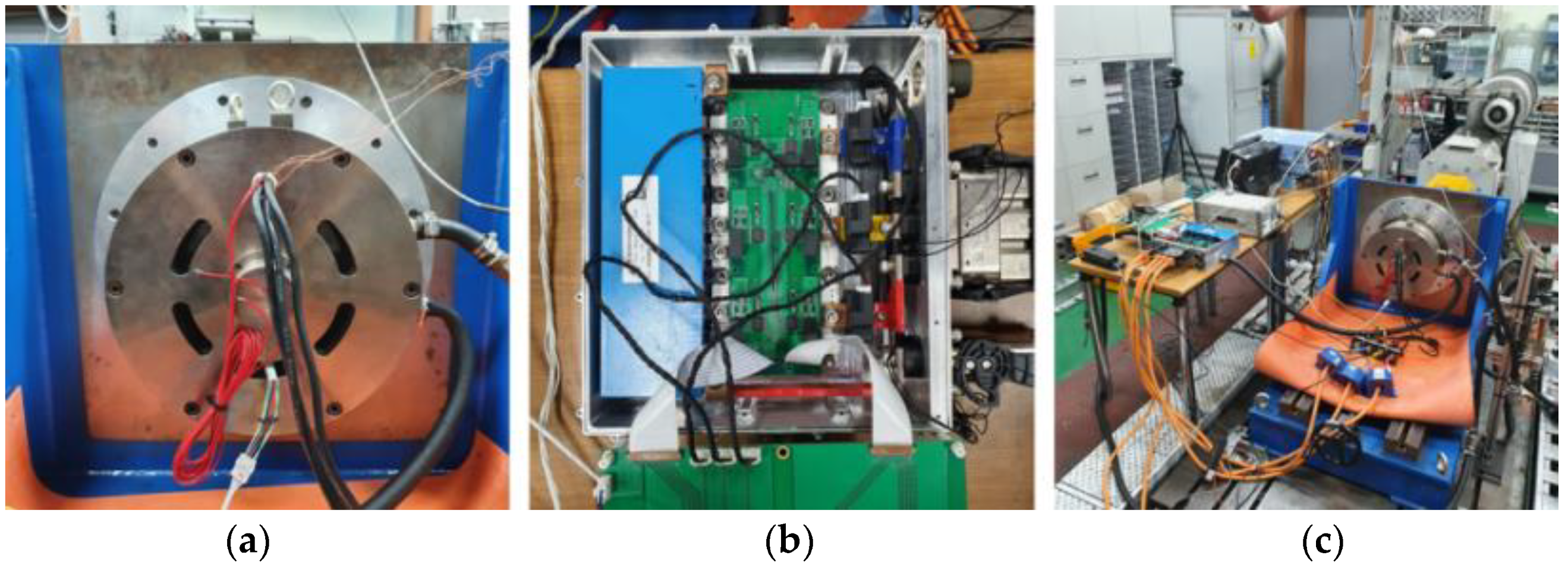
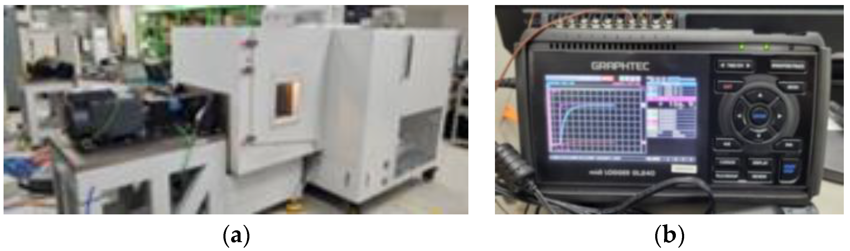
6. Experimental Results
7. Conclusions
Author Contributions
Funding
Institutional Review Board Statement
Informed Consent Statement
Data Availability Statement
Conflicts of Interest
References
- El Hajji, T.; Hlioui, S.; Louf, F.; Gabsi, M.; Mermaz-Rollet, G.; Belhadi, M. Optimal Design of High-Speed Electric Machines for Electric Vehicles: A Case Study of 100 kW V-Shaped Interior PMSM. Machines 2023, 11, 57. [Google Scholar] [CrossRef]
- Zhao, X.; Kou, B.; Huang, C.; Zhang, L. Optimization Design and Performance Analysis of a Reverse-Salient Permanent Magnet Synchronous Motor. Machines 2022, 10, 204. [Google Scholar] [CrossRef]
- Liu, C.; Xu, Y.; Zou, J.; Yu, G.; Zhuo, L. Permanent magnet shape optimization method for PMSM air gap flux density harmonics reduction. CES Trans. Electr. Mach. Syst. 2021, 5, 284–290. [Google Scholar] [CrossRef]
- Chen, H.; Demerdash, N.A.O.; EL-Refaie, A.M.; Guo, Y.; Hua, W.; Lee, C.H.T. Investigation of a 3D-Magnetic Flux PMSM With High Torque Density for Electric Vehicles. In IEEE Transactions on Energy Conversion; IEEE: New York, NY, USA, 2022; Volume 37, pp. 1442–1454. [Google Scholar] [CrossRef]
- Ion, C.P.; Calin, M.D.; Peter, I. Design of a 3 kW PMSM with Super Premium Efficiency. Energies 2023, 16, 498. [Google Scholar] [CrossRef]
- Gong, C.; Deng, F. Design and Optimization of a High-Torque-Density Low-Torque-Ripple Vernier Machine Using Ferrite Magnets for Direct-Drive Applications. In IEEE Transactions on Industrial Electronics; IEEE: New York, NY, USA, 2022; Volume 69, pp. 5421–5431. [Google Scholar] [CrossRef]
- Fasolo, A.; Alberti, L.; Bianchi, N. Performance Comparison Between Switching-Flux and IPM Machines with Rare-Earth and Ferrite PMs. In IEEE Transactions on Industry Applications; IEEE: New York, NY, USA, 2014; Volume 50, pp. 3708–3716. [Google Scholar] [CrossRef]
- Prakht, V.; Dmitrievskii, V.; Kazakbaev, V.; Ibrahim, M.N. Comparison between rare-earth and ferrite permanent magnet flux-switching generators for gearless wind turbines. Energy Rep. 2020, 6 (Suppl. S9), 1365–1369. [Google Scholar] [CrossRef]
- Chen, Y.; Cai, T.; Zhu, X.; Fan, D.; Wang, Q. Analysis and Design of a New Type of Less-Rare-Earth Hybrid-Magnet Motor With Different Rotor Topologies. In IEEE Transactions on Applied Superconductivity; IEEE: New York, NY, USA, 2020; Volume 30, pp. 1–6. [Google Scholar] [CrossRef]
- Tahanian, H.; Aliahmadi, M.; Faiz, J. Ferrite Permanent Magnets in Electrical Machines: Opportunities and Challenges of a Non-Rare-Earth Alternative. In IEEE Transactions on Magnetics; IEEE: New York, NY, USA, 2020; Volume 56, pp. 1–20. [Google Scholar] [CrossRef]
- Bian, T.; Zhou, T.; Zhang, Y. Preparation and Applications of Rare-Earth-Doped Ferroelectric Oxides. Energies 2022, 15, 8442. [Google Scholar] [CrossRef]
- Wang, Y.; Bianchi, N.; Qu, R. Comparative Study of Non-Rare-Earth and Rare-Earth PM Motors for EV Applications. Energies 2022, 15, 2711. [Google Scholar] [CrossRef]
- Rao, D.; Bagianathan, M. Selection of Optimal Magnets for Traction Motors to Prevent Demagnetization. Machines 2021, 9, 124. [Google Scholar] [CrossRef]
- Jeong, G.; Kim, H.; Lee, J. A Study on the Design of IPMSM for Reliability of Demagnetization Characteristics-Based Rotor. In IEEE Transactions on Applied Superconductivity; IEEE: New York, NY, USA, 2020; Volume 30, pp. 1–5. [Google Scholar] [CrossRef]
- Zhang, Y.; Xiang, Z.; Zhu, X.; Quan, L.; Jiang, M. Anti-Demagnetization Capability Research of a Less-Rare-Earth Permanent-Magnet Synchronous Motor Based on the Modulation Principle. In IEEE Transactions on Magnetics; IEEE: New York, NY, USA, 2021; Volume 57, pp. 1–6. [Google Scholar] [CrossRef]
- Zhang, W.; Li, G.-J.; Zhu, Z.-Q.; Ren, B.; Chong, Y.C.; Michon, M. Demagnetization Analysis of Modular SPM Machine Based on Coupled Electromagnetic-Thermal Modelling. Energies 2023, 16, 131. [Google Scholar] [CrossRef]
- Dobzhanskyi, O.; Grebenikov, V.; Gouws, R.; Gamaliia, R.; Hossain, E. Comparative Thermal and Demagnetization Analysis of the PM Machines with Neodymium and Ferrite Magnets. Energies 2022, 15, 4484. [Google Scholar] [CrossRef]
- Ge, S.; Qiu, L.; Zhang, Z.; Guo, D.; Ren, H. Integrated Impacts of Non-Ideal Factors on the Vibration Characteristics of Permanent Magnet Synchronous Motors for Electric Vehicles. Machines 2022, 10, 739. [Google Scholar] [CrossRef]
- Li, Z.; Yu, X.; Wang, X.; Xing, X. Optimization and Analysis of Cogging Torque of Permanent Magnet Spherical Motor. In IEEE Transactions on Applied Superconductivity; IEEE: New York, NY, USA, 2021; Volume 31, pp. 1–5. [Google Scholar] [CrossRef]
- Wu, L.; Chen, H.; Yu, T.; Sun, C.; Wang, L.; Ye, X.; Zhai, G. Robust Design Optimization of the Cogging Torque for a PMSM Based on Manufacturing Uncertainties Analysis and Approximate Modeling. Energies 2023, 16, 663. [Google Scholar] [CrossRef]
- Hao, W.; Zhang, G.; Liu, W.; Liu, H.; Wang, Y. Methods for Reducing Cogging Force in Permanent Magnet Machines: A Review. Energies 2023, 16, 422. [Google Scholar] [CrossRef]
- Song, S.-W.; Pyo, H.-J.; Nam, D.-W.; Lee, J.; Kim, W.-H. Irreversible Demagnetization Improvement Process of Hybrid Traction Motors with Dy-Free Magnets. Machines 2023, 11, 4. [Google Scholar] [CrossRef]


| Description | Value | Unit |
|---|---|---|
| Pole/Slot/Phase | 16/24/3 | - |
| Power | 35 | kW |
| Maximum speed/Rated speed | 6000/1770 | rpm |
| Maximum current/Rated current | 205/102.5 | Arms |
| Maximum torque/Rated torque | 205/102.5 | Nm |
| Stator diameter | 280 | mm |
| Rotor diameter | 200 | mm |
| Turns/Number of parallel | 69/8 | - |
| Dy-free magnet residual flux density | 1.31 | - |
| Dy-free magnet Coercive force (At 20 °C) | −984 | kA/m |
| Dy-free magnet Coercive force (At 150 °C) | −488 | kA/m |
| Description | Conventional Model | Final Model | Unit |
|---|---|---|---|
| Cogging torque (pk to pk) | 3.96 | 1.81 | Nm |
| Torque ripple (pk to pk) | 43.6 | 29.41 | |
| Noload back emf | 78.2 | 76.9 | Vrms |
| Irreversible demagnetization ratio | 0.55 | 0.61 | % |
| Conventional Model | Final Model | Unit | |
|---|---|---|---|
| Core loss | 140.37 | 123.95 | W |
| Eddy current loss | 41.41 | 36.93 | W |
| Copper loss | 630.38 | 630.38 | W |
| Inverter Input Voltage | Rotating Speed | Output Torque | Maximum Output |
|---|---|---|---|
| 302.6 (V) | 2000 (rpm) | 187.26 (Nm) | 39.23 (W) |
| Inverter Input Voltage | Inverter Input Voltage | Motor Output | Maximum Efficiency |
|---|---|---|---|
| 302.1 (V) | 17,242 (W) | 16.53 (W) | 95.91 (%) |
| Temperature Conditions | 20 °C | 150 °C |
|---|---|---|
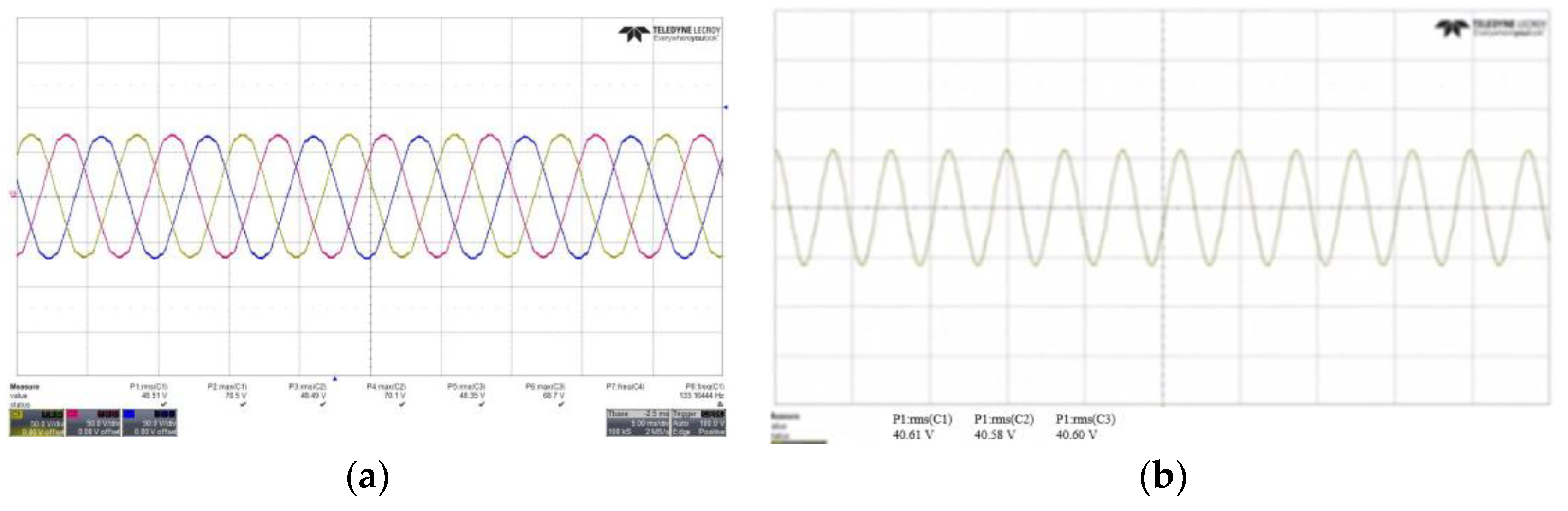
| Noload back emf U phase (Vrms) | 48.51 | 40.61 |
| temperature reduction ratio (%) (Compared to 20 °C) | - | 16.28 |
Disclaimer/Publisher’s Note: The statements, opinions and data contained in all publications are solely those of the individual author(s) and contributor(s) and not of MDPI and/or the editor(s). MDPI and/or the editor(s) disclaim responsibility for any injury to people or property resulting from any ideas, methods, instructions or products referred to in the content. |
© 2023 by the authors. Licensee MDPI, Basel, Switzerland. This article is an open access article distributed under the terms and conditions of the Creative Commons Attribution (CC BY) license (https://creativecommons.org/licenses/by/4.0/).
Share and Cite
Song, S.-W.; Kim, W.-H.; Lee, J.; Jung, D.-H. Design to Reduce Cogging Torque and Irreversible Demagnetization in Traction Hybrid Motor Using Dy-free Magnet. Machines 2023, 11, 345. https://doi.org/10.3390/machines11030345
Song S-W, Kim W-H, Lee J, Jung D-H. Design to Reduce Cogging Torque and Irreversible Demagnetization in Traction Hybrid Motor Using Dy-free Magnet. Machines. 2023; 11(3):345. https://doi.org/10.3390/machines11030345
Chicago/Turabian StyleSong, Si-Woo, Won-Ho Kim, Ju Lee, and Dong-Hoon Jung. 2023. "Design to Reduce Cogging Torque and Irreversible Demagnetization in Traction Hybrid Motor Using Dy-free Magnet" Machines 11, no. 3: 345. https://doi.org/10.3390/machines11030345