Article

A Novel Methodology to Enhance the Smooth Running of the PM BLDC Motor Drive Using PWM-PWM Logic and Advance Angle Method

1
Department of Electrical and Electronics Engineering, Anil Neerukonda Institute of Technology and Sciences, Visakhapatnam 531162, India
2
Department of Electrical and Electronics Engineering, Aditya Institute of Technology & Management (A), Tekkali 532201, India
3
Department of Electrical Power and Machines, Faculty of Engineering, Alexandria University, Alexandria 21544, Egypt
4
Magnetics and Materials Research Group, School of Engineering, Cardiff University, Cardiff CF24 3AA, UK
*
Author to whom correspondence should be addressed.
Machines 2023, 11(1), 41; https://doi.org/10.3390/machines11010041
Submission received: 7 November 2022 / Revised: 23 December 2022 / Accepted: 26 December 2022 / Published: 30 December 2022
(This article belongs to the Special Issue Permanent Magnet Motors: State of the Art)

Abstract

:
This paper addresses the active torque ripple compensation of a permanent magnet brushless direct-current motor (PMBLDC) drive with a new pulse width modulation (PWM) technique and advance angle method. Torque ripple is a well-known problem in BLDC motors which is produced by a discrepancy between the stator current and the back electromotive force (back-emf) waveforms. The advanced angle method proposed in this paper generates a maximum torque in the PM BLDC motor by decreasing the displacement between the phase voltage and phase current in proportion to the load. Further, a simple and comprehensive PWM-PWM logic is proposed in this paper to reduce the torque ripples. The test results show that the BLDC motor drive achieves good steady-state performance while maintaining a quick dynamic response. The performance of the PWM-PWM logic and advance angle method, have been tested and compared with the practical results for the characteristics of DC bus voltage, DC bus current, electromagnetic torque, shaft torque, mechanical torque, phase voltage, phase current and PWM signal.

1. Introduction

1.1. Background and Motivation

Due to the rapid development in control technology in recent years, the BLDC motor has wide applications such as actuation, positioning, servo and variable speed applications. For accurate speed and position control applications, speed regulation is an important part of the BLDC motor drive. Controllers with maximum bandwidth are essential to handle the torque ripple frequencies in order to synthesize the right input voltages in the framework of torque ripple reduction.

1.2. Literature Review

The authors of [1] proposed a magnetic circuit model for carrying out theoretical mathematical analysis of the magnetic field in the single-phase BLDC slim fan motor, but the too-high axial magnetic force ripple causes the vibration in the axial direction. In [2], a special study and research on the individual and combined effects of stator inter-turn fault and rotor demagnetization effects in a surface-mounted PM BLDC motor were presented. As well, the comprehensive modeling of faults was accomplished using well-established fault modeling techniques. But the reduction in torque ripples was not addressed in this paper. The authors of [3] considered the square wave phase current injection through predictive current control strategies for the PM BLDC motor in the stationary plane, whereas the PI-PWM control failed to maintain average torque after 67% of the rated speed.
In [4], a detailed discussion of the PM BLDC motor demagnetization fault was presented. The modeling of the machine was carried out using various available techniques such as the method based on an equivalent electric circuit or the analytical method that takes into account several hypotheses in order to simplify the analysis, but more torque ripples were generated during the demagnetization fault in the BLDC motor. The authors of [5] proposed an enhanced flux observation method to filter the harmonic content under the rotor synchronous reference frame for the PM BLDC motor with a rotor damper cage. The authors of [6] proposed a technique to minimize the overall torque ripples for the three-phase PM BLDC motor drive in the presence of phase current shift error. The maximum phase shift is limited which is not proportional to the load. Authors of [7] proposed a two-phase dual-stator axial-flux PM BLDC motor with an ironless rotor for higher torque per magnet volume which is restricted only to the pull drive technique. In [8], a response surface method for the optimal design of a PM BLDC motor with a three-dimensional structure was presented. The authors of [9] presented a phase lock loop control algorithm for the deployment of precision control of a sensorless PM BLDC motor. Authors of [10] used the virtual work method for obtaining the analytical expression of cogging torque with asymmetrical rotor magnets in the PM BLDC motor. The authors of [11] implemented support vector regression and adaptive neuro-fuzzy inference system-based controllers for the position control of a three-phase PM BLDC motor. Authors of [12] proposed a simple and efficient method to achieve the integrated control of motoring and regenerative braking of the BLDC motor. Authors of [13] aimed at the problems of the poor adaptive ability in the current control methods for the BLDC motor, an adaptive fuzzy proportional integral derivative controller was proposed to realize the better control performance of speed for the BLDC motor. In [14], a fast commutation error correction method was proposed to ensure ideal torque performance and low power consumption at constant or rapidly varying speeds. But when the motor was operating at high frequencies, the corresponding switching losses were addressed. In [15], Fourier series-based phase delay compensation was realized by designing an inverter circuit that switches the phase voltages according to the phase currents. Authors of [16] presented a novel sensorless start-up strategy for a 315 kW high-speed magnetic suspension BLDC motor with small inductance and non-ideal back electromotive force. The magnitudes of the transient currents are very high even though the BLDC motor is operating at low speeds. In [17], a combination of two and three-phase switching methods to reduce switching loss was presented and in the conduction region, the conventional two-phase switching topology was used to reduce the switching loss. Authors of [18] presented a torque ripple compensation technique for a BL DC motor drive that is operated without a DC link capacitor. But the responses are taking more time to settle down and also have more ripples. The design of a digital current control applied to a variable-speed low inductance Brushless DC motor drive was presented in [19]. Authors of [20] proposed a torque ripple minimization method for BLDC motors by using a novel switching technique. The commutation judgment determines the normal conduction period and commutation period by tracking the mode of operation according to the speed. Ripples are present in the experimental three-phase currents. In [21], three fault-tolerant control methods are compared to reduce torque ripple by controlling the magnitude and phase angle of healthy phase currents under open circuit failure to remove the second harmonic component of torque, which has a large influence on torque ripples. A novel driving technique including phase advance and overlap is introduced in order to obtain the minimum torque ripples. With a careful selection of the phase advance and overlap angles, a minimum torque ripple of 12% has been achieved [22]. In [23], an equivalent magnetizing current method was employed in the mechanical finite element analysis to adjust the leading angle of the BLDC motor and also studied the electrical characteristics analysis as well as the mechanical noise and vibration of the BLDC motor.

1.3. Contributions

The major contributions of the paper are outlined as follows,
  • Sliding mode controller is designed to identify the speed error in the BLDC motor.
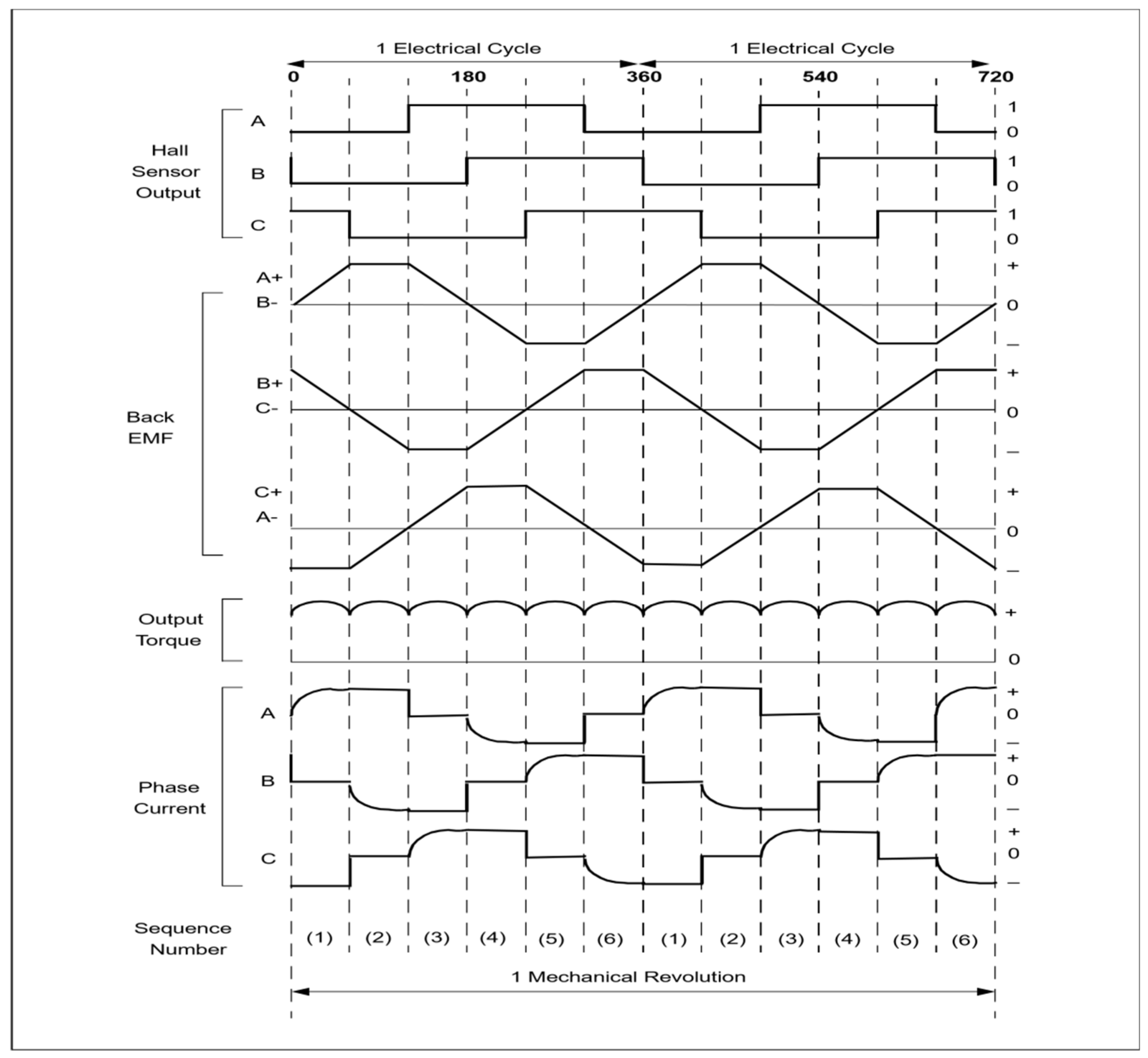
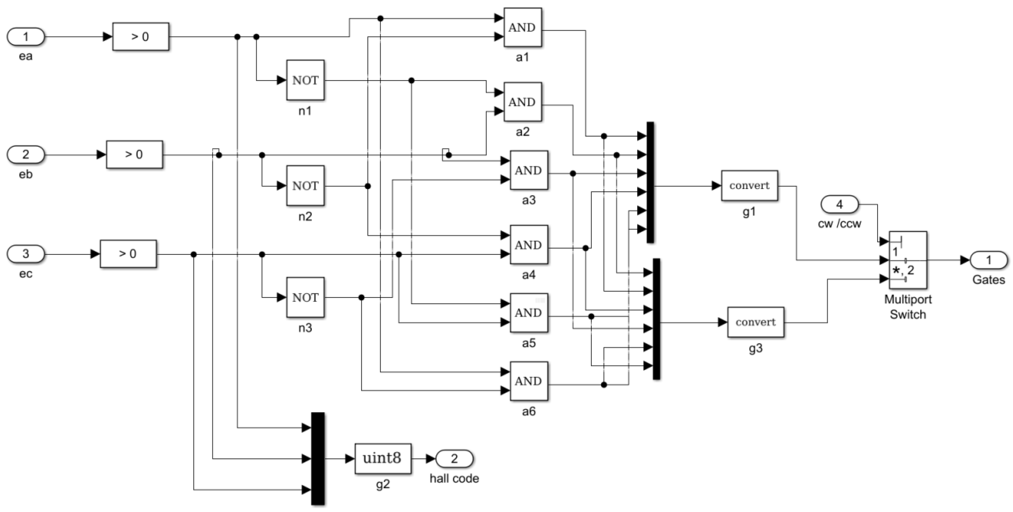
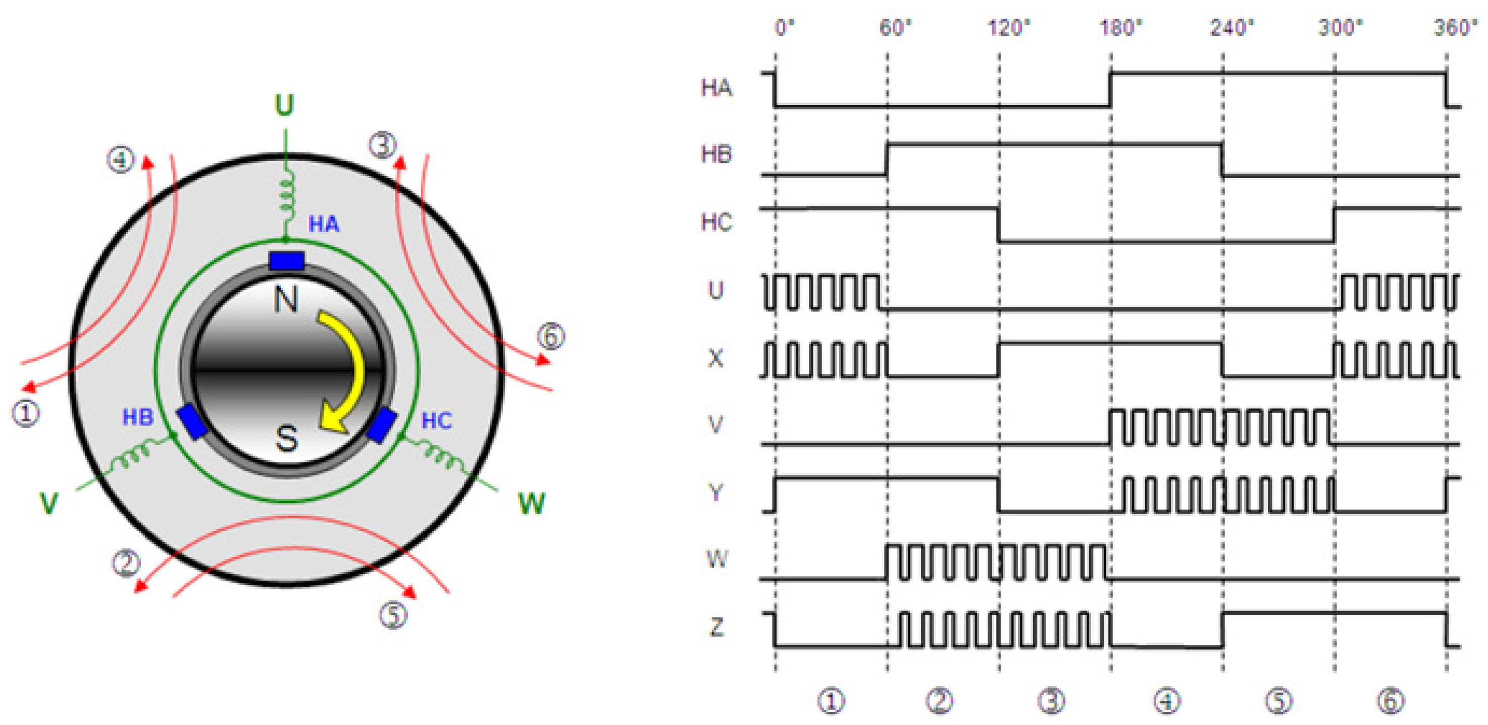
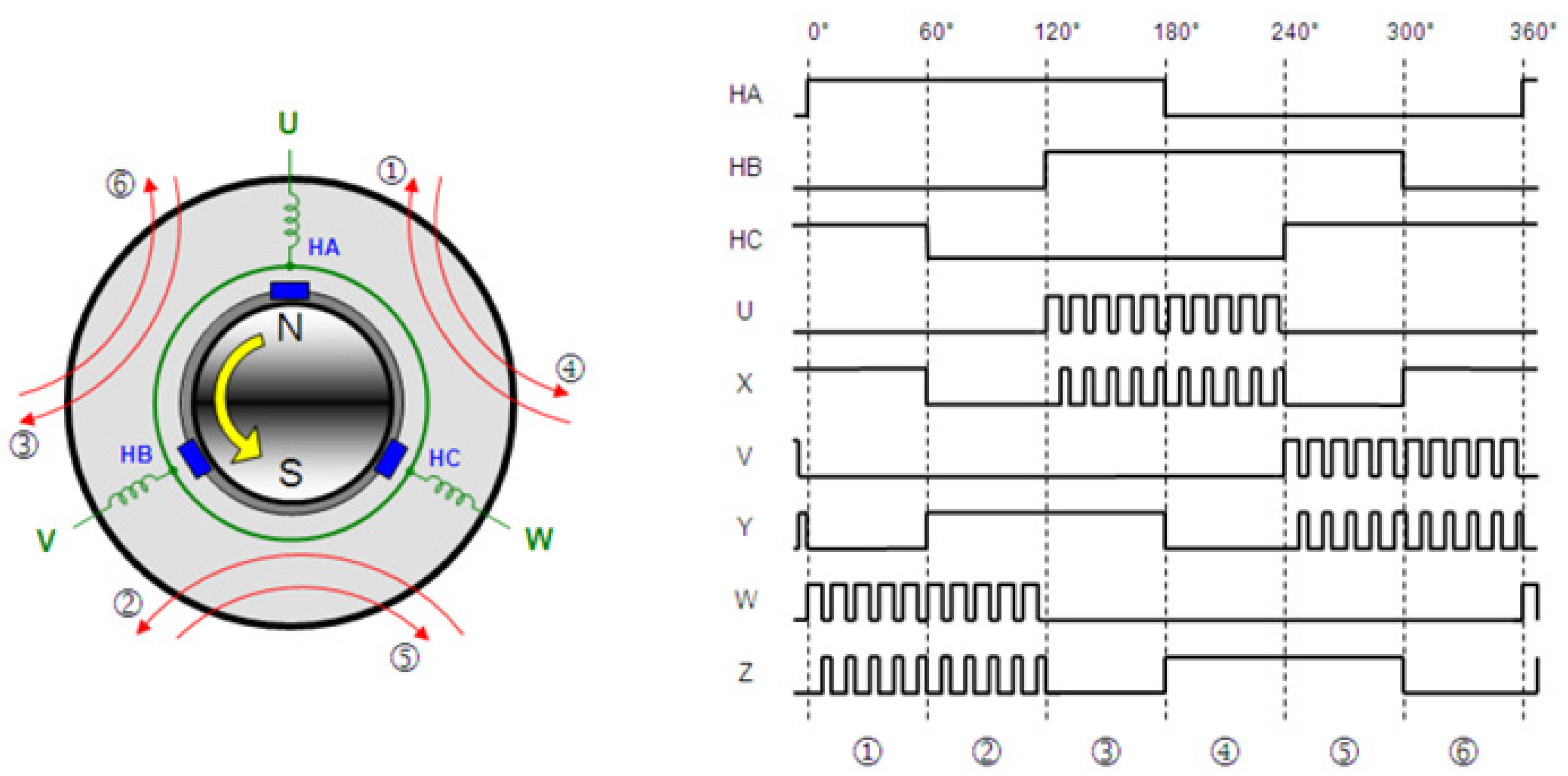
  • Back-emf waveforms are generated using hall sensor signals.
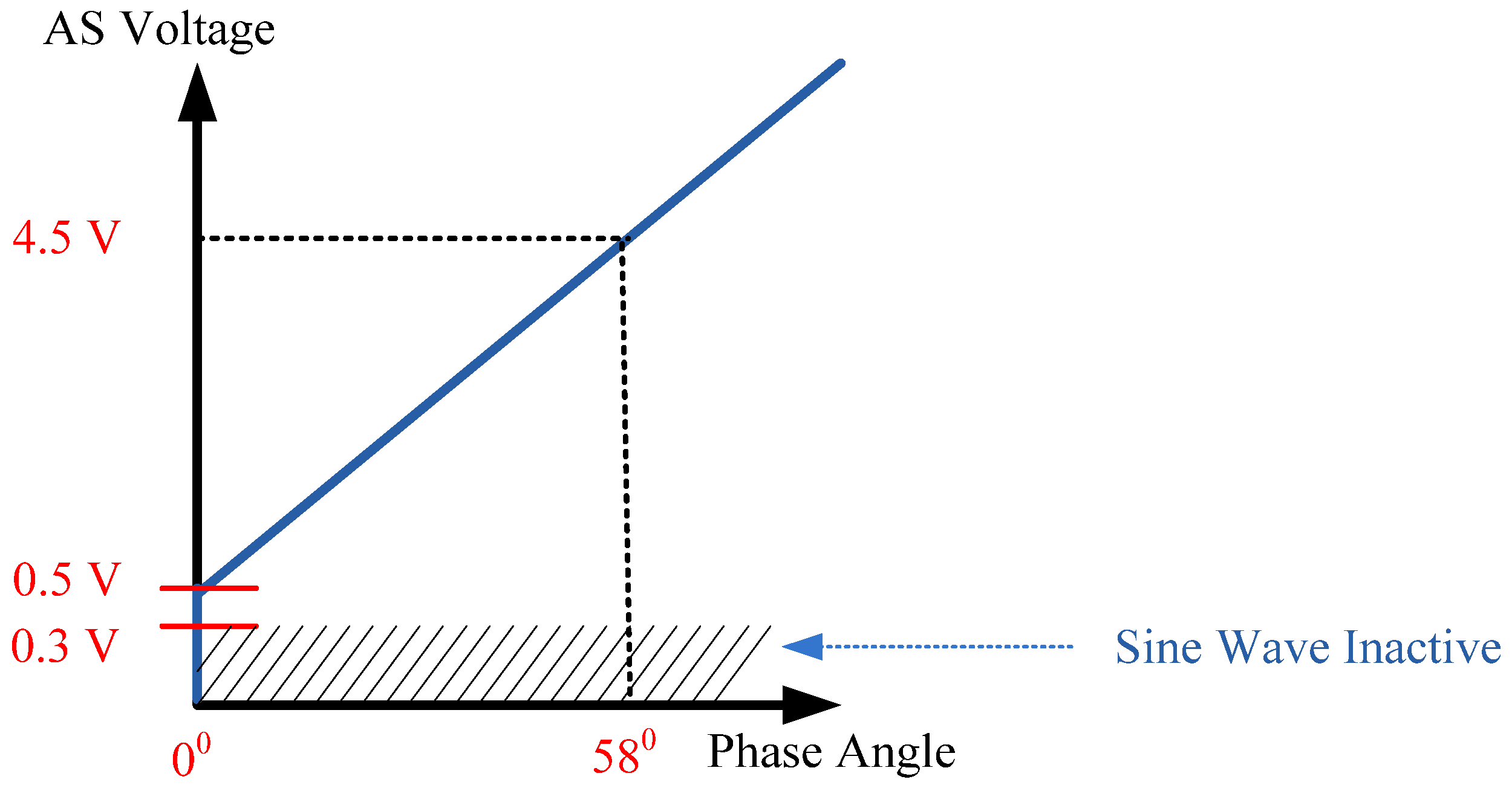
  • Advanced angle method (AS voltage method) is implemented to adjust the lead angle.
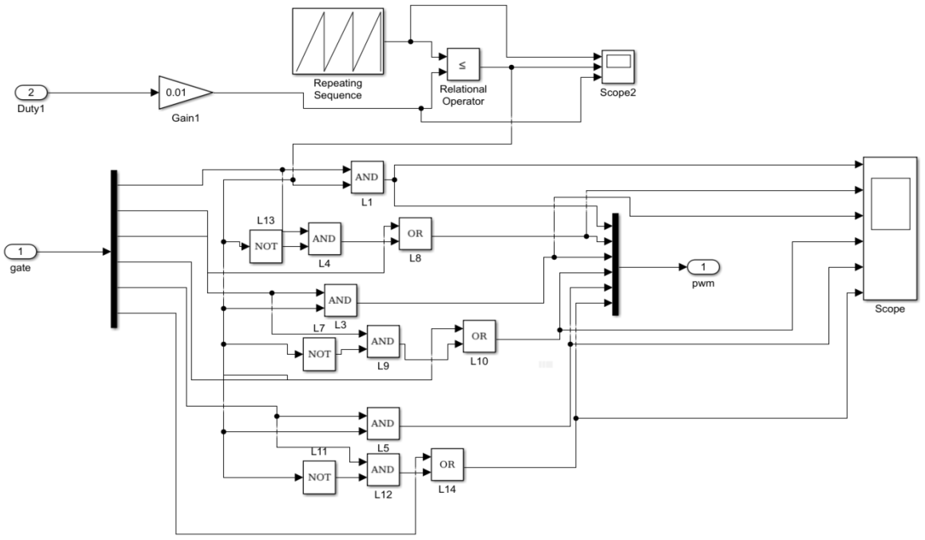
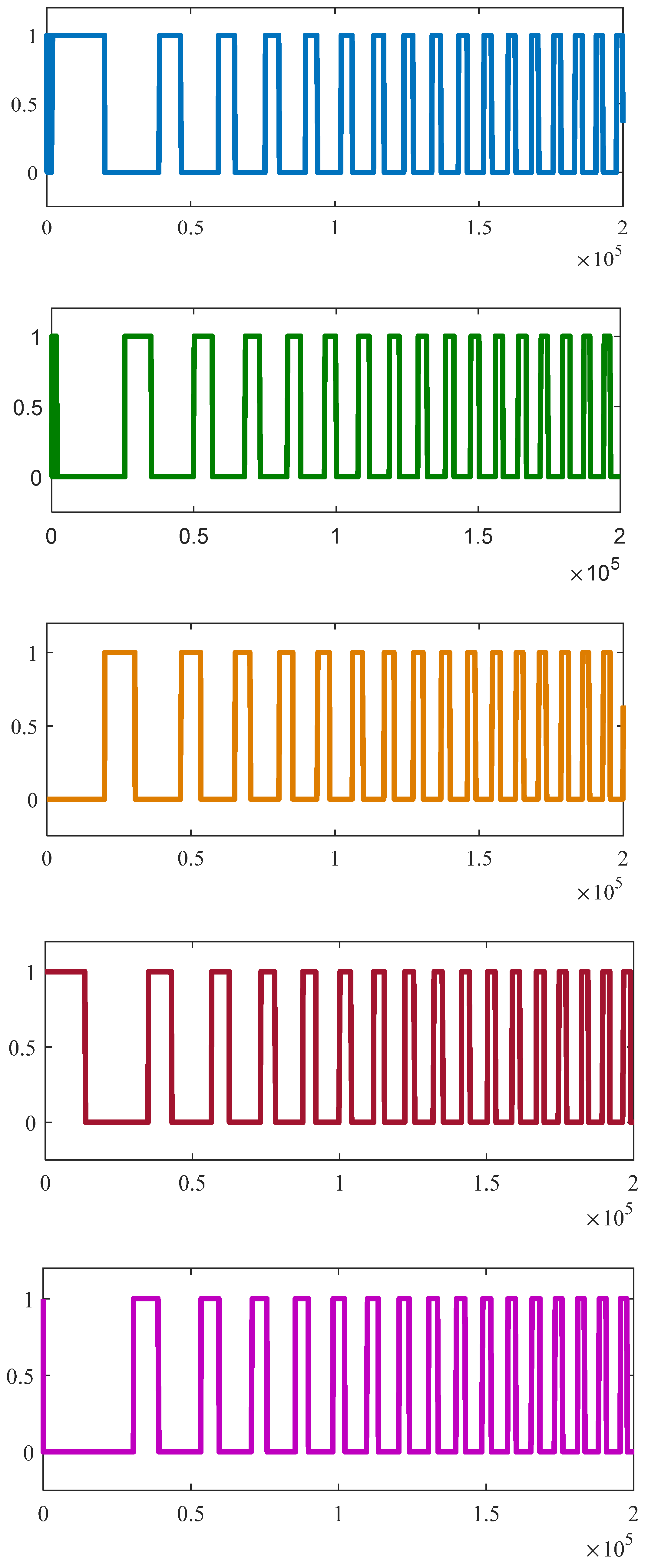
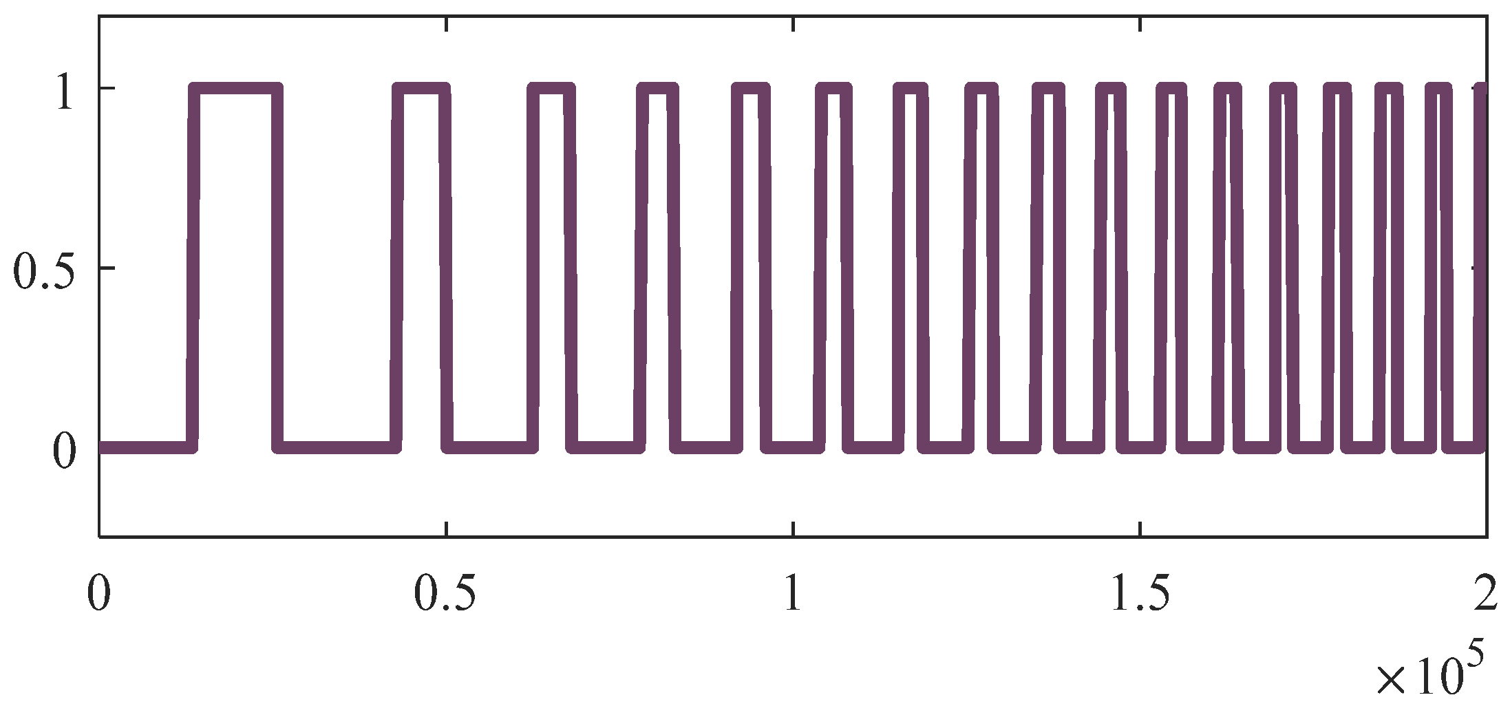
  • PWM-PWM commutation technique is developed to drive the BLDC motor.
  • The toque ripples are minimized for the dynamic load.
This paper proposes a PWM-PWM commutation technique and implemented an advanced angle method to minimize the torque ripples in the BLDC motor for dynamic load. In this paper, the speed error is identified by using a sliding mode controller [24]. The rest of the paper is organized as follows. In Section 2, the materials of the BLDC motor and controllers are described. In Section 3, the method for minimization of torque ripples of the BLDC motor is presented. Results and discussions are presented in Section 4. Finally, the conclusions are discussed in Section 5.

2. Materials of the BLDC Motor and Controllers

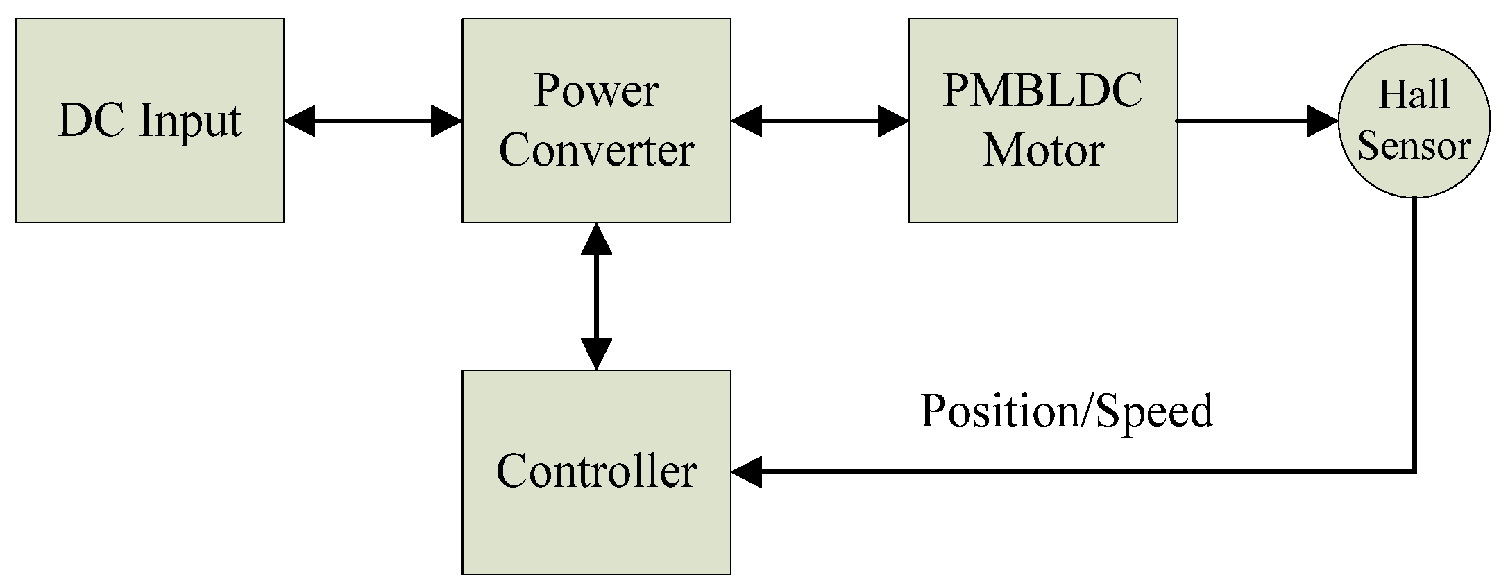
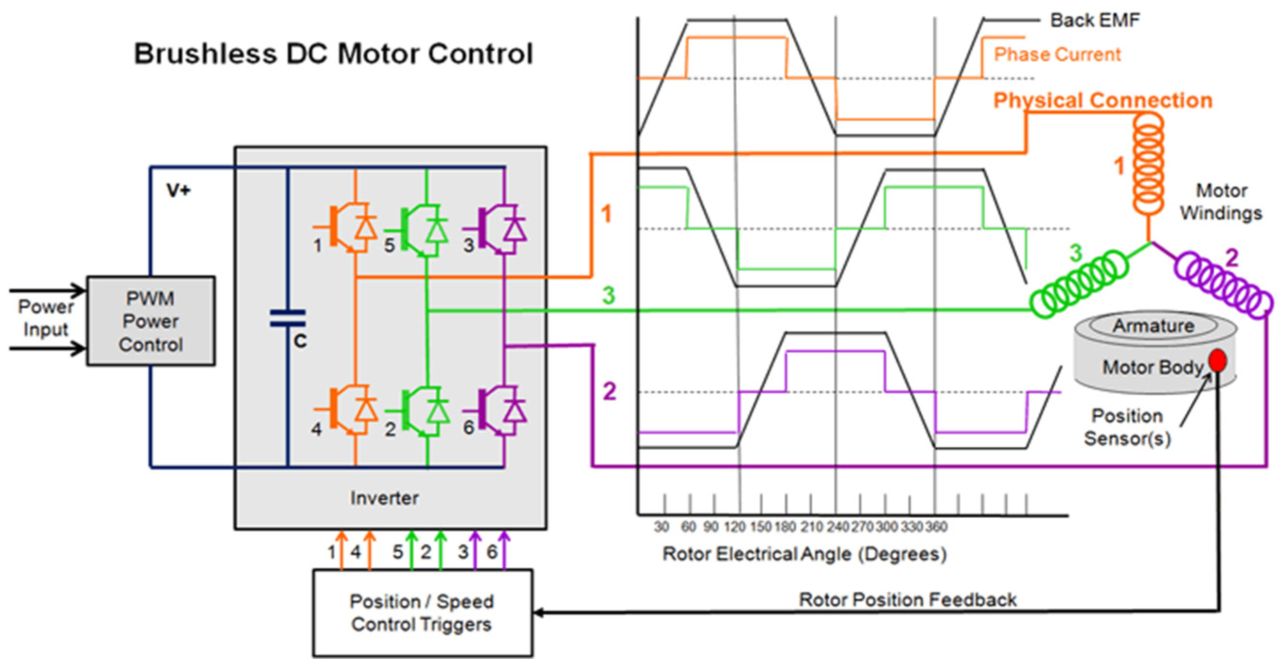
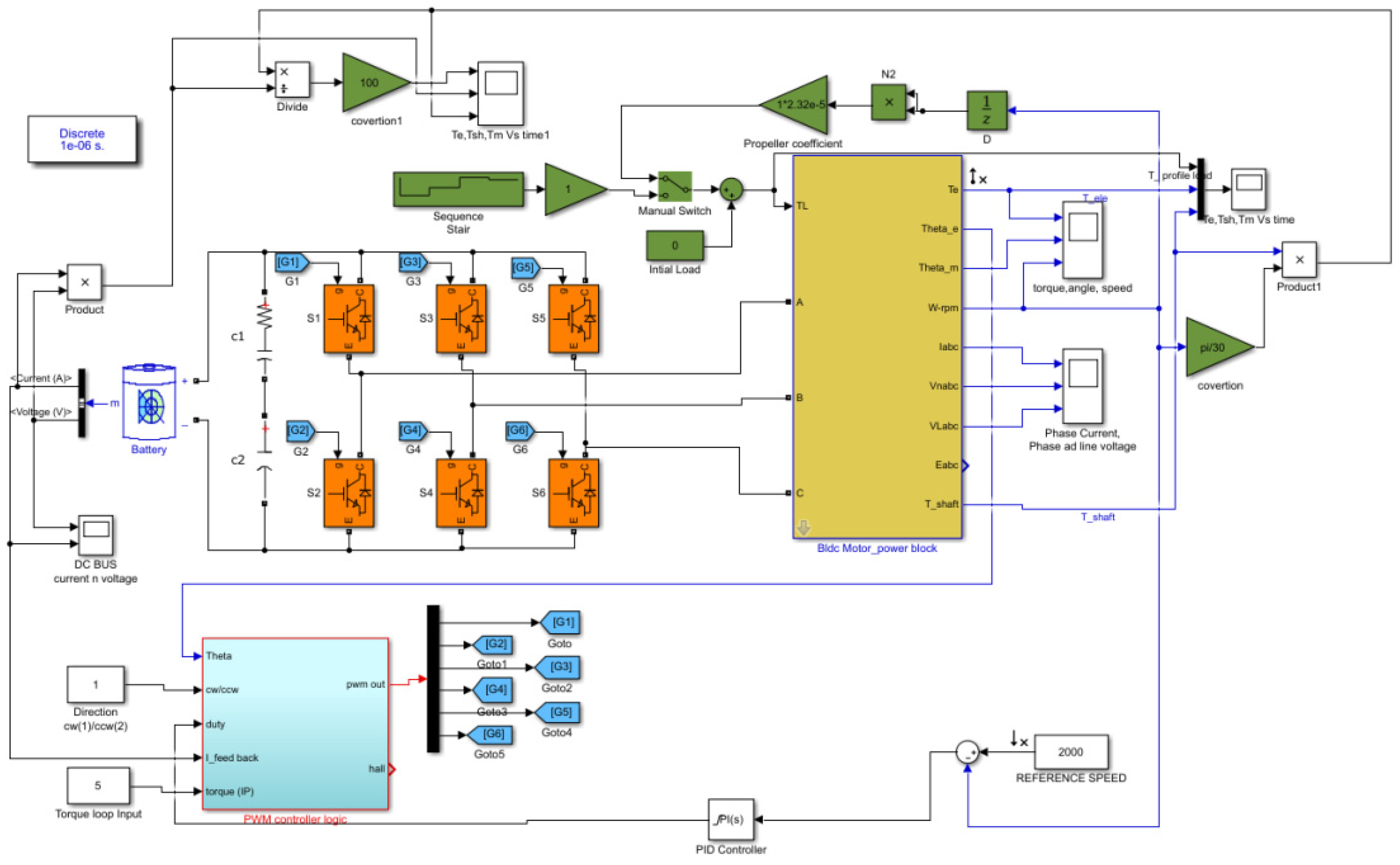
2.1. Machine Model and Power Control Theory

The basic control of PMBLDC is shown in Figure 1. The mathematical representation of the PMBLDC motor and the expressions for stator phase windings are well presented in [13,24].
The shape of the back-emf induced in the stator coils is trapezoidal and is commonly controlled by trapezoidal control [25]. The stator magnetic field can be rotated by commutating two phases at a time in this control, as shown in Figure 2. There are six alternative rotor alignments, each 60° apart. It means for every 60°, the two correct phases have to be commutated. Six-step control, also known as trapezoidal control, allows us to make the rotor spin.
The rotor position can be identified by the hall sensors [26] to properly commutate the motor at the right times with the correct phases. Commutation occurs in such a way that the rotor never aligns with the magnetic field of the stator but rather chases it. The motor produces zero torque when the magnetic fields of the rotor and stator are completely aligned and develops a maximum torque when the fields are separated by 90°. To keep the BLDC motor running at a constant speed, it requires a constant voltage which is produced by a three-phase converter. However, in order to drive the BLDC motor at different speeds, the variable voltage must be applied. This can be achieved by PWM logic. The BLDC motor phase current lags the phase voltage because of the inductance of the winding and this angle depends on the speed [27]. If the BLDC motor is running at high speed, then this angle will be greater. To achieve maximum torque, the phase voltage should be applied in advance to the back-emf with the phase current. Flux weakening, reduced torque, and low efficiency arise from any phase difference between back-emf and phase current. When the North pole of the rotor passes through a hall sensor, it produces a high state, and when the South pole passes through the hall sensor, it produces a low state. The three hall sensors will produce three states of the signal during any 60° electrical as shown in Figure 3. The three hall sensors will produce six states based on the rotor position. Based on the six states of hall sensors, the controller will identify the two stator windings which need to be energized. As a result, the commutation is continuous. Each phase terminal of the BLDC motor is energized by DC voltage which is electrically switched every 60° of rotation [28]. As a result, the waveform for each phase winding is a staircase with 60° for each step.
The space vector produced from these three-phase currents results in a smooth rotation. The highest torque is produced in the BLDC motor by energizing the correct phase pair in sequence to produce a smooth constant torque. But in practice, the phase current cannot change instantly from low to high. There will be transient periods of rise and fall that will generate ripples at the output, which will coincide with each phase switch. This causes a ripple in the motor’s output torque, so vibrations will be generated in the BLDC motor. When a sudden load is applied to the BLDC motor, the variation in torque is continuous and looks sinusoidal. This continuous change in torque ripple can be termed torque ripple frequency.

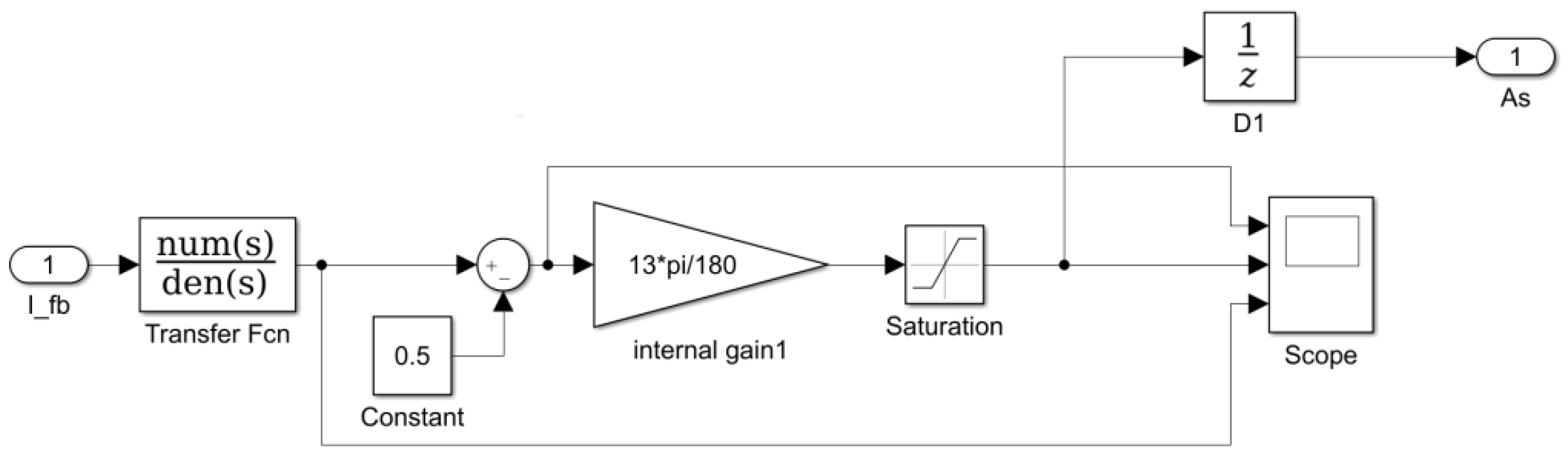
2.2. Advance Angle Method

The stator windings of the BLDC motor are excited only by using a DC voltage source. In this method, the displacement between the phase voltage and phase current is reduced by energizing the phase in advance by 0° to 58°. Later, the angle of the phase current is advanced. This reduces the lag between phase voltage and phase current in the BLDC motor. This prevents the current phase from lagging behind the back-emf, which results in lower motor output efficiency [29].

2.3. Pulse Width Modulation

In this PWM logic, with the 120° rotor magnetic pole position detection, each N-S performs 360° cycles on three hall sensors, so only six signal changes occur. The switching voltages are applied to the stator windings of the BLDC motor by PWM to modulate current through the inductor. The frequency of PWM depends on stator winding inductance and resistances [30].

3. Methodology for Minimization of Torque Ripples in the BLDC Motor

3.1. Advance Angle Adjustment

To obtain the constant torque of a BLDC motor that drives with a square-wave current of electrical 120° duration, we need to ensure that the phase current is commuted every electrical 60° degrees of rotation. Commutation induces a phase lag and deviations from the ideal square-wave current as a result of the inductance levels of the motor winding process. The torque characteristic is changed by the commutation timing because torque is derived from the multiplication of the back-emf and the phase current. The advance angle, which maximizes the torque-to-current ratio, can be calculated by analyzing the average power variation in relation to the advance angle. Once the voltage angle is advanced, the angle of the current phase angle is advanced as well. The current phase does not lag behind the back electromotive force, where lag leads to reduced motor efficiency. The current phase angle is adjusted in proportion to the load based on the AS voltage level. At full load, a full AS voltage of around 4.5 volts is applied; at no load, a minimum value of the voltage is around 0.5 volts. Here, the angle variation is considered to be linear.
The stator current flowing into the three-phase coil lags behind the three-phase voltage by an angle ϕ° due to the inductance of the winding. As a result, the stator current fails to share the same phase with the back-emf and thus generates poor torque.
Using the AS voltage level, the angle of the output voltage can be advanced by 0–58°. Once the voltage angle is advanced, the angle of the current phase angle is advanced as well. In this way, the current phase does not lag behind the back electromotive force where lag leads to reduced motor efficiency. The current phase angle is adjusted in proportion to the load based on the AS voltage level. At full load, a full AS voltage of around 4.5 volts is applied while at no load, a minimum value of the voltage is around 0.5 volts. Here, the angle variation is considered to be linear.
In this method, the displacement between phase current and phase voltage can be adjusted by the AS voltage signal as shown in Figure 4.
The lead angle block is designed to adjust the AS voltage as shown in Figure 5, keeping the equivalent feedback parameters and dead bands into consideration. The angle variation is considered to be linear.

3.2. Pulse Width Modulation Scheme

PWM is a method of reducing the average power delivered by an electrical signal by effectively chopping it up into discrete parts. The average value of the voltage (and current) fed to the load is controlled by turning the switch between supply and load on and off at a fast rate. The longer the switch is on period compared to the off periods, the higher the total power supplied to the load.
BLDC motor controller with a three-phase square-wave drive; the detection position is at the 120° rotor magnetic pole. With just a small number of peripheral components, it can control BLDC motors on a stand-alone basis. In coordination with the controller, it can also be used for complicated motor control applications. It is suitable for motor control for various products, such as fans, water/oil pumps, tooling machines, etc.
A square-wave PWM commutation mode is known as PWM-PWM [31]. This simulation uses a square-wave drive of PWM-PWM commutation to start the motor and drive it. In standalone mode, so long as the motor’s running status complies with the conditions required for the square-wave drive.
With the 120° rotor magnetic pole position detection, each N-S performs 360° cycles on three hall sensors, so only six signal changes occur. As long as the corresponding current directions are provided on the three-phase windings of stators based on six signal changes, rotating magnetic fields are generated to attract the rotor to rotate. Each type of Hall signal corresponds to one PWM output type; there are six different PWM output types in 360°, with commutation occurring every 60°. Therefore, it is also called a six-step, square-wave drive.
At any instant, one of these three phases is continuously ON for every 120° (two steps), while the other two phases get conducted at different 60° low sides. Each phase outputs PWM every two steps, so it is called PWM-PWM commutation mode. PWM-PWM commutation mode facilitates the use of a high-side driver IC in combination with a driver circuit whose high and low sides both use an N-channel MOSFET or IGBT as the driver circuit for the motor. This is because the high side does not keep being conducted during any commutating period, and when the high side closes, its low side with the same phase is conducted, and as a result, synchronous rectifying is enabled to improve efficiency. At this moment, the bootstrap circuit of the high-side driver IC has the chance to charge, supplementing energy for the driving MOSFET. Although PWM output using these commutation features is a somewhat simple driver circuit that does not require concern about turn-on failure or partial conduction of the high-side MOSFET, between two-step continuous PWM output, negative current may return to the power source side when the low sides of the other two phases exchange conduction. Such a negative current is one of the major noise sources for the square-wave drive. When U-phase outputs PWM, at the instant low-side conduction of the W-phase switches to low-side conduction of the V-phase; when both the low side of the MOSFET and PWM of U-phase close, polarities of the inductance of U-phase and W-phase are reversed. Thus, the energy that has been stored in the inductance becomes negative current IW-U and returns to the power supply side via the built-in diode of the high-side MOSFET of the W-phase. In this way, a negative current is generated.
A new PWM-PWM logic is implemented for the controller circuit. The emf signal block is fed by theta. Unlike a brushed DC motor, the commutation of a BLDC motor is controlled electronically. In order to rotate the BLDC motor, the stator windings should be energized in a defined sequence. It is important to know the rotor position (theta) in order to understand which winding will be energized following the energizing sequence. The rotor position is sensed using Hall Effect sensors embedded into the stator. Most BLDC motors have three Hall sensors embedded in the stator on the non-driving end of the motor. Whenever the rotor magnetic poles pass near the Hall sensors, they give a high or low signal, indicating the N or S pole is passing near the sensors. Based on the combination of these three Hall sensor signals, the exact sequence of commutation can be determined and back-emf can be generated.
The back-EMFs are generated based on theta value. The output of this emf signal block truth table is generated. The truth table is generated by a gate signal based on the out of back-emf. Based on this truth table, multiple ON-pulses are created at which U and X, V and Y, W and Z pairs enter the active position. The remaining states of the gates are not disturbed as shown in Figure 6.
Unlike a brushed DC motor, the commutation of a BLDC motor is controlled electronically. In order to rotate the BLDC motor, the stator windings should be energized in a defined sequence. It is important to know the rotor position (theta) in order to understand which winding will be energized following the energizing sequence. The rotor position is sensed using Hall Effect sensors embedded into the stator. Most BLDC motors have three Hall sensors embedded in the stator on the non-driving end of the motor.
Whenever the rotor magnetic poles pass near the Hall sensors, they give a high or low signal, indicating the N or S pole is passing near the sensors. Based on the combination of these three Hall sensor signals, the exact sequence of commutation can be determined and back-emf can be generated.
Figure 7 shows the logic diagram from the truth table by applying the K-map and deducing relations for each gate signal. The PWM width depends on the closed-loop control algorithm. Directional change is also considered in the deduction of logic [32].
A revolving magnetic field is generated to attract rotors to rotate [33], as shown in Figure 8. The PWMs continuously operate every 120° in all instances, whereas the other two phases operate at distinct 60° low sides. The PWM-PWM commutation mode is named after the fact that each phase outputs PWM for every two steps. By changing the current directions, a revolving magnetic field is created in the reverse direction to rotate the rotor in a counterclockwise direction as shown in Figure 9.
The BLDC motor speed and torque control by using PWM and advance angle method with a reference speed of 2000 rpm are shown are Figure 10.
When the BLDC motors are used in underwater defense applications, because of torque ripples, the machine will generate vibrations so that the enemy can identify the location of this BLDC motor. So, torque ripples must be minimized to reduce the vibrations caused by the BLDC motor for smoother and noiseless operation.
BLDC motors find applications in every segment of the market. Automotive, appliance, industrial controls, automation, aviation and defense so on, have applications for BLDC motors. Out of these, we can categorize the type of BLDC motor control into three major types: constant load, varying load, and positioning applications.

4. Results and Discussions

A PM BLDC motor driving scheme is used to test the control approaches using simulation and mathematical modelling. The parameters of the motor utilized in this paper are presented in Table 1.
The motor is switched to PWM-PWM commutation logic triggering pulses as shown in Figure 11. Figure 12 shows that the variation in current is proportional to the applied load. In Figure 13, the changes in line currents are observed and supplied from the DC bus voltage. So, the DC bus currents that are drawn from the DC bus voltage also have a proportional effect. These effects are proportional to the load applied at t = 0, and the corresponding torque also varied to meet the current variations can be observed in Figure 14 For about 100 N-m torque the DC bus current is around 100 A for a given DC bus voltage of 470 V. Figure 13 shows the line currents, phase and line voltage variation with respective times during loading conditions.
The rotor angle and variation in torques with profile load are shown in Figure 14. The electromagnetic and shaft torques almost coincide in all cases, and the torque has no ripples even higher-power BLDC motor operates at 2000 rpm, along with the phase current shift method. The variation in torques with a stair-case load is shown in Figure 15. The electromagnetic and shaft torques almost coincide in all cases.
The electromagnetic and shaft torques almost coincide and can be observed in Figure 15, and the torque has no ripples even higher-power BLDC motor operates at 2000 rpm, PWM-PWM logic along with the advance angle method produces a smooth torque without any ripples.
Figure 16 and Figure 17 show the real-time response of the motor at different load conditions. In Figure 16 the phase currents and DC Bus currents are overlapped, the DC bus currents have more ripple content at every peak due to inductance at full load, and also Figure 17 gives a clear picture of lagging currents with respective phase voltages at full load. These phase currents are drawn from the DC bus. So, these DC bus currents have more ripple than the phase currents because of the inductance effect. The hall and respective phase PWMs signals are also presented. The phase current (Magma) in Figure 16 has a peak value in each cycle, which reflects the DC bus current (red). This is going to deteriorate the performance of the machine at loading conditions.
Figure 18 and Figure 19 show the phase currents and relative phase voltages with an advanced angle loop mechanism for various loads. In Figure 18, the phase voltage and current (blue) slightly lead the voltage at 70% duty cycle. At full load, both phase and line voltage are almost aligned with each other as shown in Figure 19. The DC bus current has fewer peaks and ripple content also less. This shows the more uniform behavior of the drive compared to earlier results.

Discussions

PWM-PWM logic along with the Advance angle Method for the BLDC motor is simulated using mathematical relations and is incorporated into the simulation block. The characteristics of BLDC motors are studied in detail in different modes of operation and loading profiles. In the report, a high-power motor’s parameters are taken as reference and simulation results are validated with the practical testing results. By using the AS voltage angle method, the phase lag between phase voltage and phase current can be decreased by increasing the AS voltage angle is proportional to the load current which can be shown in the graph. So, the dynamic response also can be improved in addition to the torque response of a BLDC motor drive. The proposed techniques are successfully implemented in a practical high-power BLDC motor and the results are validated with the practical responses.

5. Conclusions

The realization of PWM-PWM logic along with the advance angle method for the BLDC motor is used to reduce the torque ripples even if the high-power BLDC motor is loaded. If the developed torque has no ripples, then there will not be any vibrations or noise generated during operation. This is the main requirement for underwater defense applications. This paper studies the characteristics of BLDC motors in different modes of operation and loading profiles. A high-power motor’s parameters are taken as a reference, and simulation results are validated with the practical testing results. The detailed study of torque and advanced angle loop features are considered to simulate the developed model so as to verify the novelty of the control logic by using controllers. It is justified that the features are well-suited to operate the drive in rugged and user-defined loading profiles.

Author Contributions

Conceptualization, B.S., R.S., B.P., H.K., M.S. and B.A.S.; methodology, B.S., R.S., B.P., H.K., M.S. and B.A.S.; software, B.S., R.S., B.P., H.K., M.S. and B.A.S.; validation, B.S., R.S., B.P., H.K., M.S. and B.A.S.; formal analysis, B.S., R.S., B.P., H.K., M.S. and B.A.S.; investigation, B.S., R.S., B.P., H.K., M.S. and B.A.S.; resources, B.S., R.S., B.P., H.K., M.S. and B.A.S.; writing—original draft preparation, B.S., R.S., B.P., H.K., M.S. and B.A.S.; writing—review and editing, B.S., R.S., B.P., H.K., M.S. and B.A.S.; visualization, B.S., R.S., B.P., H.K., M.S. and B.A.S.; supervision, B.S., R.S., B.P., H.K., M.S. and B.A.S.; project administration, B.S., R.S., B.P., H.K., M.S. and B.A.S.; funding acquisition, B.S., R.S., B.P., H.K., M.S. and B.A.S. All authors have read and agreed to the published version of the manuscript.

Funding

This research received no external funding.

Data Availability Statement

The data sources employed for analysis are presented in the text.

Conflicts of Interest

The authors declare no conflict of interest.

References

  1. Tang, Z.-H.; Chen, Y.-T.; Liou, Y.-K.; Liang, R.-H. Axial Magnetic Force Analysis and Optimized Design for Single-Phase BLDC Slim Fan Motors. IEEE Trans. Ind. Electron. 2020, 68, 6840–6848. [Google Scholar] [CrossRef]
  2. Usman, A.; Rajpurohit, B.S. Modeling and Classification of Stator Inter-Turn Fault and Demagnetization Effects in BLDC Motor Using Rotor Back-EMF and Radial Magnetic Flux Analysis. IEEE Access 2020, 8, 118030–118049. [Google Scholar] [CrossRef]
  3. Trivedi, M.S.; Keshri, R.K. Evaluation of Predictive Current Control Techniques for PM BLDC Motor in Stationary Plane. IEEE Access 2020, 8, 46217–46228. [Google Scholar] [CrossRef]
  4. Usman, A.; Rajpurohit, B.S. Comprehensive Analysis of Demagnetization Faults in BLDC Motors Using Novel Hybrid Electrical Equivalent Circuit and Numerical Based Approach. IEEE Access 2019, 7, 147542–147552. [Google Scholar] [CrossRef]
  5. Li, P.; Sun, W.; Shen, J.-X. Flux Observer Model for Sensorless Control of PM BLDC Motor with a Damper Cage. IEEE Trans. Ind. Appl. 2018, 55, 1272–1279. [Google Scholar] [CrossRef]
  6. Lee, Y. A New Method to Minimize Overall Torque Ripple in the Presence of Phase Current Shift Error for Three-Phase BLDC Motor Drive. Can. J. Electr. Comput. Eng. 2019, 42, 225–231. [Google Scholar] [CrossRef]
  7. Yazdan, T.; Atiq, S.; Kwon, B.-I.; Baloch, N.; Kwon, J.-W. Two Phase Dual-Stator Axial-Flux PM BLDC Motor with Ironless Rotor Using Only-Pull Drive Technique. IEEE Access 2019, 7, 82144–82153. [Google Scholar] [CrossRef]
  8. Jo, S.-T.; Shin, H.-S.; Lee, Y.-G.; Lee, J.-H.; Choi, J.-Y. Optimal Design of a BLDC Motor Considering Three-Dimensional Structures Using the Response Surface Methodology. Energies 2022, 15, 461. [Google Scholar] [CrossRef]
  9. Yoon, Y.-H.; Kim, J.-M. Precision control of a sensorless PM BLDC motor using PLL control algorithm. Electr. Eng. 2017, 100, 1097–1111. [Google Scholar] [CrossRef]
  10. Anuja, T.A.; Doss, M.A.N. Asymmetrical Magnets in Rotor Structure of a Permanent Magnet Brushless DC Motor for Cogging Torque Minimization. J. Electr. Eng. Technol. 2022, 17, 1271–1279. [Google Scholar] [CrossRef]
  11. Chopra, V.; Singh, N.J.; Kumar, R.; Sharma, V. Position Control of PMBLDC Motor Using SVR- and ANFIS-Based Controllers. Natl. Acad. Sci. Lett. 2021, 45, 57–60. [Google Scholar] [CrossRef]
  12. Fan, P.; Ma, R.; Zhang, Y.; Dang, Z.; Li, T. Bipolar modulation of brushless DC motor with integrated control of motoring and regenerative braking. J. Power Electron. 2022, 22, 234–242. [Google Scholar] [CrossRef]
  13. Wang, T.; Wang, H.; Hu, H.; Lu, X.; Zhao, S. An adaptive fuzzy PID controller for speed control of brushless direct current motor. SN Appl. Sci. 2022, 4, 71. [Google Scholar] [CrossRef]
  14. Jin, H.; Liu, G.; Li, H.; Chen, B.; Zhang, H. A Fast Commutation Error Correction Method for Sensorless BLDC Motor Considering Rapidly Varying Rotor Speed. IEEE Trans. Ind. Electron. 2021, 69, 3938–3947. [Google Scholar] [CrossRef]
  15. Lee, M.; Kong, K. Fourier-Series-Based Phase Delay Compensation of Brushless DC Motor Systems. IEEE Trans. Power Electron. 2017, 33, 525–534. [Google Scholar] [CrossRef]
  16. Chen, S.; Liu, G.; Zhu, L. Sensorless Startup Strategy for a 315-kW High-Speed Brushless DC Motor with Small Inductance and Nonideal Back EMF. IEEE Trans. Ind. Electron. 2018, 66, 1703–1714. [Google Scholar] [CrossRef]
  17. Park, J.; Lee, D.-H. Simple Commutation Torque Ripple Reduction Using PWM With Compensation Voltage. IEEE Trans. Ind. Appl. 2020, 56, 2654–2662. [Google Scholar] [CrossRef]
  18. Ransara, H.K.S.; Madawala, U.K. A Torque Ripple Compensation Technique for a Low-Cost Brushless DC Motor Drive. IEEE Trans. Ind. Electron. 2015, 62, 6171–6182. [Google Scholar] [CrossRef]
  19. de Almeida, P.M.; Valle, R.L.; Barbosa, P.G.; Montagner, V.F.; Cuk, V.; Ribeiro, P.F. Robust Control of a Variable-Speed BLDC Motor Drive. IEEE J. Emerg. Sel. Top. Ind. Electron. 2020, 2, 32–41. [Google Scholar] [CrossRef]
  20. Kumar, P.; Bhaskar, D.V.; Behera, R.K.; Muduli, U.R. A Modified torque ripple minimization technique for BLDC motor drive using synthesized current phase compensation. In Proceedings of the 2020 IEEE International Conference on Industrial Tech-nology (ICIT), Buenos Aires, Argentina, 26–28 February 2020; pp. 127–132. [Google Scholar] [CrossRef]
  21. Park, H.; Kim, T.; Suh, Y. Comparison of fault-tolerant control methods reducing torque ripple of multi-phase BLDC motor drive system under open-phase fault. In Proceedings of the 2021 IEEE Energy Conversion Congress and Exposition (ECCE), virtual, 10–14 October 2021; pp. 4987–4993. [Google Scholar] [CrossRef]
  22. Taha, M.; Thabet, A.M.; Mahgoub, O.A. Brushless DC motor drive with minimum torque ripple. In Proceedings of the 2016 Eighteenth International Middle East Power Systems Conference (MEPCON), Cairo, Egypt, 27–29 December 2016; pp. 888–893. [Google Scholar] [CrossRef]
  23. Lee, S.-J.; Hong, J.-P.; Jang, W.-K. Characteristics comparison of BLDC motor according to the lead angles. In Proceedings of the 2012 IEEE Vehicle Power and Propulsion Conference, Seoul, Republic of Korea, 9–12 October 2012; pp. 879–883. [Google Scholar] [CrossRef]
  24. Murali, S.B.; Rao, P.M. Adaptive sliding mode control of BLDC motor using cuckoo search algorithm. In Proceedings of the 2018 2nd International Conference on Inventive Systems and Control (ICISC), Coimbatore, India, 19–20 January 2018; pp. 989–993. [Google Scholar] [CrossRef]
  25. Tao, Z.; Sun, J.; Li, H.; Huang, Y.; Li, H.; Xu, T.; Wu, H. A Radial-flux Permanent Magnet Micromotor with 3D Solenoid Iron-core MEMS In-chip Coils of High Aspect Ratio. IEEE Electron Device Lett. 2020, 41, 1090–1093. [Google Scholar] [CrossRef]
  26. Shin, H.S.; Shin, K.H.; Jang, G.H.; Cho, S.K.; Jung, K.H.; Choi, J.Y. Experimental Verification and 2D Equivalent Analysis Techniques of BLDC Motor with Permanent Magnet Overhang and Housing Integrated Rotor Core. EEE Trans. Appl. Supercond. 2020, 30, 5201805. [Google Scholar] [CrossRef]
  27. Yang, L.; Zhao, J.; Yang, L.; Liu, X.; Zhao, L. Investigation of a Stator-Ironless Brushless DC Motor with Non-Ideal Back-EMF. IEEE Access 2019, 7, 28044–28054. [Google Scholar] [CrossRef]
  28. Zhang, Z.; Deng, Z.; Gu, C.; Sun, Q.; Peng, C.; Pang, G. Reduction of Rotor Harmonic Eddy-Current Loss of High-Speed PM BLDC Motors by Using a Split-Phase Winding Method. IEEE Trans. Energy Convers. 2019, 34, 1593–1602. [Google Scholar] [CrossRef]
  29. Sashidhar, S.; Reddy, V.G.P.; Fernandes, B.G. A Single-Stage Sensorless Control of a PV-Based Bore-Well Submersible BLDC Motor. IEEE J. Emerg. Sel. Top. Power Electron. 2018, 7, 1173–1180. [Google Scholar] [CrossRef]
  30. Liu, K.; Yin, M.; Hua, W.; Ma, Z.; Lin, M.; Kong, Y. Design and Analysis of Halbach Ironless Flywheel BLDC Motor/Generators. IEEE Trans. Magn. 2018, 54, 8109305. [Google Scholar] [CrossRef]
  31. FCM8201 Three-Phase Sine-Wave BLDC Motor Controller. Available online: www.bdtic.com/DataSheet/FAIRCHILD/AN-8201.pdf (accessed on 1 October 2022).
  32. Gu, C.; Wang, X.; Shi, X.; Deng, Z. A PLL-Based Novel Commutation Correction Strategy for a High-Speed Brushless DC Motor Sensorless Drive System. IEEE Trans. Ind. Electron. 2017, 65, 3752–3762. [Google Scholar] [CrossRef]
  33. Dasari, M.; Reddy, A.S.; Kumar, M.V. Modified Luo converter based FOPID controller for torque ripple minimization in BLDC drive system. J. Ambient Intell. Humaniz. Comput. 2022, 13, 1–18. [Google Scholar] [CrossRef]
Figure 1. Components of the PMBLDC drive.
Machines 11 00041 g001
Figure 2. Control block diagram of the BLDC motor.
Machines 11 00041 g002
Figure 3. Hall sensor signal, back-emf, output torque and phase current.
Machines 11 00041 g003
Figure 4. Internal view of the advance angle adjustment.
Machines 11 00041 g004
Figure 5. Phase angle correction for current leading.
Machines 11 00041 g005
Figure 6. Digital logic from truth table in PWM-PWM mode.
Machines 11 00041 g006
Figure 7. PWM Generation in PWM-PWM mode.
Machines 11 00041 g007
Figure 8. PWM-PWM Commutation at CW/CCW = 1.
Machines 11 00041 g008
Figure 9. PWM-PWM Commutation at CW/CCW = 0.
Machines 11 00041 g009
Figure 10. Simulation of PMBLDC motor with PWM-PWM logic and advanced angle method.
Machines 11 00041 g010
Figure 11. PWM-PWM commutation logic triggering pulses.
Machines 11 00041 g011aMachines 11 00041 g011b
Figure 12. DC Bus values (a) Voltage vs Time and (b) Current Vs Time.
Machines 11 00041 g012
Figure 13. BLDC motor voltages and currents: (a) Line current vs Time (b) Line voltage vs Time and (c) Phase voltage vs Time.
Machines 11 00041 g013aMachines 11 00041 g013b
Figure 14. The variations in Te, Rotor angle and speed: (a) Electromagnetic torque vs Time (b) Rotor angle vs Time and (c) Speed Vs Time.
Machines 11 00041 g014
Figure 15. T-Electromagnetic, T-Shaft, T-Mechanical Vs Time during CW with staircase load.
Machines 11 00041 g015
Figure 16. Phase currents, and DC bus currents are aligning with respective Hall, PWM signal Vs time.
Machines 11 00041 g016
Figure 17. Phase voltages, and phase currents overlap with the respective PWMs Vs time at full Load.
Machines 11 00041 g017
Figure 18. Phase currents, phase voltages with lead angle adjustment Vs time at 70% duty cycle.
Machines 11 00041 g018
Figure 19. Phase currents, Phase voltages with lead angle adjustment at full load.
Machines 11 00041 g019
Table 1. Parameters of the PM BLDC Motor.
SymbolQuantityValue of Parameter
JMoment of inertia0.155 kg m2
BFriction coefficient0.0031575 kg/ms
KbBack-emf constant0.07 volt/rad/sec
LInductance0.0000462 H
PNumber of pole pairs9
RResistance per phase0.0127 ohms
Disclaimer/Publisher’s Note: The statements, opinions and data contained in all publications are solely those of the individual author(s) and contributor(s) and not of MDPI and/or the editor(s). MDPI and/or the editor(s) disclaim responsibility for any injury to people or property resulting from any ideas, methods, instructions or products referred to in the content.

