1. Introduction
Multiphase machines are becoming a potential solution for several high-powered applications, since they provide high reliability with an intrinsic fault-tolerance capability [
1]. Among their potential applications, they can be found in automotive, ship propulsion, and wind-energy-generation systems [
2]. The multiphase machines with multiple three-phase windings (such as six-phase, nine-phase, or eighteen-phase machines) are especially intriguing because they are compatible with common three-phase power converters. The six-phase machine is the simplest configuration that enables an extremely simple and less expensive switch from three-phase systems to multiphase systems [
3].
However, a high-performance control approach is required for controlling the system variables (e.g., speed, currents, and flux) in order to fully benefit from multiphase drives. Nonetheless, extending traditional controls from three-phase machines to multiphase machines is a challenging task [
4,
5]. In multiphase machines, it is essential to control both the machine losses (x−y subspace) and the flux/torque production (α−β subspace). As a result, field-oriented control (FOC) and direct torque control (DTC) have been studied extensively over the years [
6]. Furthermore, one of the most widely used control strategies over the past ten years has been model predictive control (MPC). Improved dynamic performance and the flexibility to accommodate different control objectives are the key benefits of MPC over conventional control techniques [
7]. However, the MPC faces some disadvantages when applied to multiphase induction motors: a high computational cost of the optimization stage proportionally to 2
n (n being the number of phases) [
8]; reduction of current harmonic distortion [
9]; the rotor quantities are not measured and act as a disturbance in the predictive model [
10]; the drive performance can be highly affected by not using exact system parameters [
11]; parameter identification [
12], fault detection and post-fault operation. The MPC takes into account a restricted number of switching states given by the power converters, where the mathematical model is used to predict the future behavior of the controlled variables [
13]. The best switching state is then selected as the one to use in the subsequent sampling time, since it has the minimum error in the established cost function [
7].
The first implementation of a MPC strategy for six-phase motor drives was reported in [
14]. In such work, it was proven that, by including components related to the current harmonics in the cost function, the current quality improves; however, it substantially increases the computational effort. Predictive control has been incorporated with model-free control (MFC) in recent research. Model-free predictive control (MFPC) approaches may address issues such as parameter mismatches, disturbances, and model uncertainties since they do not require prior knowledge of the system model. The estimate of the system’s unknown terms presents the biggest difficulty for the MFPC technique. Thus, MFPC methods have increased the complexity of the control system [
11]. The six-phase machine can have two different neutral configurations: single isolated neutral point (1NP) and dual isolated neutral points (2NP) [
15]. Therefore, in the literature, six-phase machines are usually studied in healthy conditions with a 2NP configuration, whereas six-phase machines with 1NP are studied for fault tolerant controls [
16].
The occurrence of inter-turn short circuit faults (ITSCFs) in motor drives promote a number of negative side-effects [
17]. A sudden increase in temperature that encourages insulation breakdown is one of the most serious effects of ITSCFs. The machine may be completely destroyed in a few seconds due to the ITSCF’s high potential for scaling. The development of quick and accurate diagnostic techniques is essential for avoiding such results. The converter and motor’s current and voltage data demonstrate alterations brought on by electrical damage. The stray flux signal is also extremely vulnerable to these effects [
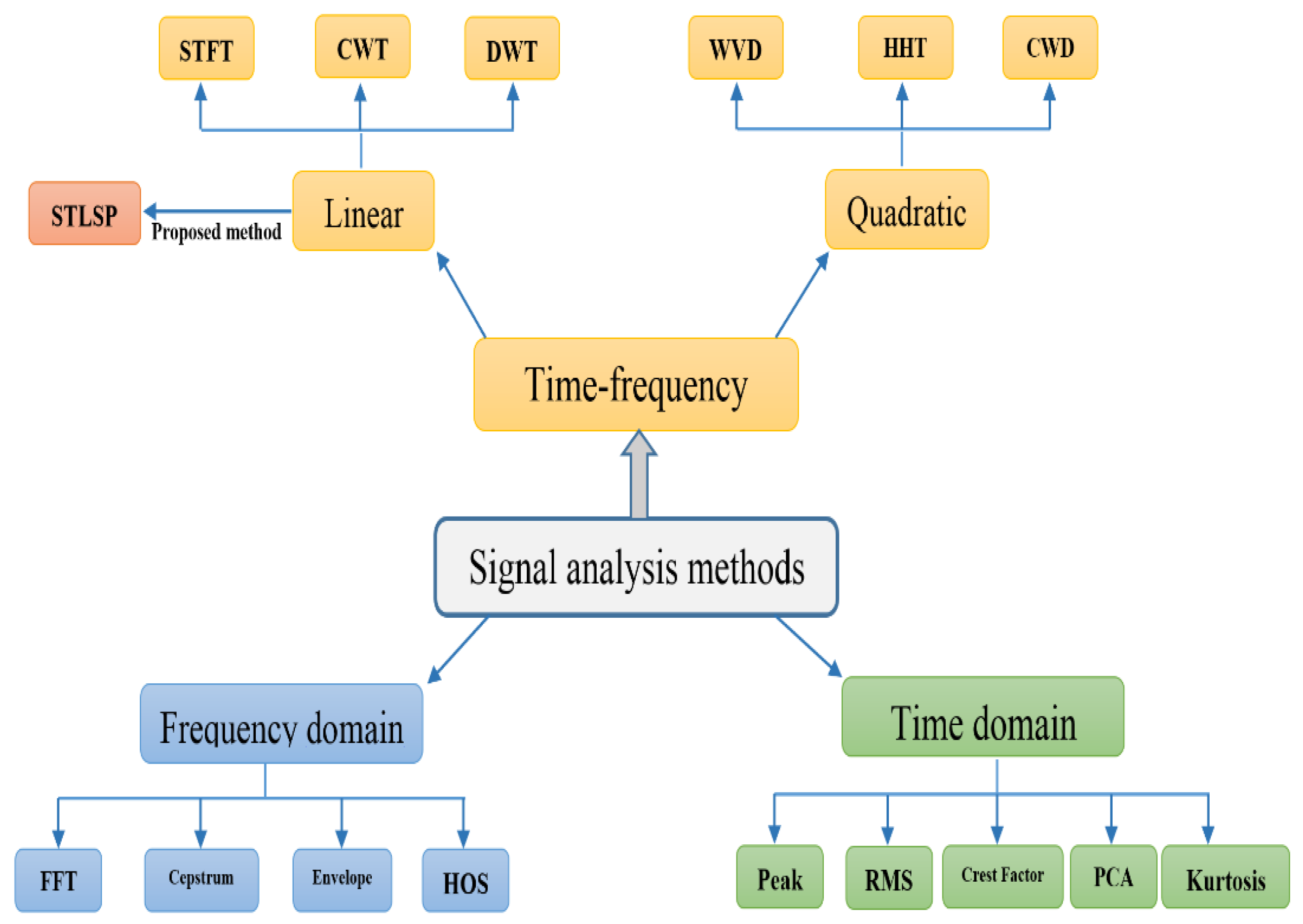
18]. It is clear from examining recent developments in the diagnostics of induction motors (IM) and permanent magnet synchronous motors (PMSMs) that three main strategies have developed over time [
19,
20]: (1) diagnostics based on mathematical modelling; (2) diagnostics based on artificial intelligence (AI) methods and techniques; and (3) diagnostics based on signal analysis (
Figure 1).
Currently, mathematical modeling is used to evaluate signal-analysis methods, differentiate fault signatures, and perform diagnostics based on residual computation [
21]. Less commonly, fault symptoms are generated using mathematical models of AC machines with different flaws, in order to train neural network-based fault detectors or classifiers. In fault-tolerant control systems, where observers are utilized for failure detection and compensation, fault-diagnostic procedures based on mathematical models, in particular, those utilizing different estimators of motor state variables and parameters, are applied [
22,
23,
24].
Neural network (NN)-based AI strategies have received a lot of attention recently, especially for IM drives [
22,
23,
24]. An artificial neural network technique was used in [
25] to identify stator faults, and an hidden Markov model was used in [
26] for the same purpose.
To separate the fingerprints for fault diagnosis, signal analysis methods use a range of signal processing techniques. These signatures can be used for “manual” diagnostics, depending on the knowledge of existing experts, or for far more complicated diagnostics, based on knowledge-based processes, leading to fault diagnostics systems that use AI techniques. Therefore, it is becoming more crucial to detect motor drive issues using signal analysis techniques [
19,
20]. Increases in odd triple-line-current harmonics were utilized in [
27] to detect ITSCFs. Technologies for digital signal processing enable the extraction of symptoms (features) unique to a certain failure type. The three possible signal processing techniques are time-domain techniques, frequency-domain techniques, and time–frequency techniques (
Figure 1). Most time-domain methods rely heavily on statistical analysis. They use, among other signal properties, peak levels, root mean square (RMS) or mean values, crest factor, principal component analysis (PCA), and kurtosis. Today, the most widely utilized approaches for diagnosing electric motors, including 6PMs, PMSMs, and SynRMs, are time–frequency-domain and frequency-domain methods [
19,
20].
Due to the limitations of the frequency-domain-based approaches, such as the inability to get information about the moment of failure, more and more attempts have been performed to use T-FMs, such as short-time Fourier transform (STFT), Wigner–Ville distribution/transform (WVD/WVT), wavelet/wavelet packet transform (WT/WPT), Hilbert/Hilbert–Huang transform (HT/HHT), empirical-mode-decomposition (EMD), and others, for AC machine diagnostics [
28,
29]. It is necessary to fully comprehend and characterize the operational circumstances and their boundaries in order to execute these approaches correctly and effectively. Therefore, choosing the right window size is crucial because it must correspond to the signal frequencies that are unique to a certain defect, which are not always known beforehand. Time and frequency resolution must be traded off depending on the application, with the longer window having higher frequency resolution and the smaller window having better time resolution [
28]. As the STFT method uses a larger window, the signal within it may be viewed as practically stationary, and better results can be produced than when using FFT, and it is better suited for non-stationary signals with low dynamics. As a result, for highly dynamic systems, such as PMSM drives, multiresolution signal processing techniques, such as WT, yield superior results. Time and frequency resolution are consistently delivered by the continuous wavelet transform (CWT). However, using this method necessitates accurate parameter adjustment, which includes determining the primary wavelet function. A constant resolution over the whole frequency range is determined by the use of this function.
The well-known motor current signature analysis (MCSA) technique and the extended Park’s vector approach (EPVA) are also suitable for diagnostics of ITSCFs, particularly in IMs [
30]. Due to the drawbacks of FFT, such as the requirement for signal stationarity and the lengthy measurement time that goes along with it, and the rising demand for computation in embedded systems using microcontrollers, more sophisticated high-order spectra (HOS)-based signal processing techniques have become increasingly popular in recent years.
A new method that relies on the calculation of the Park’s flux vector and spectrum analysis of its modulus was designed in [
31] to identify low-severity ITSCFs in three-phase IMs. It has been determined that iron core saturation, load fluctuations, and unbalanced supply voltage (USV) operating conditions, among other things, have a detrimental effect on this method. Despite the success of the disclosed procedures, their potential for usage in the industrial setting is still constrained by their high costs and/or complexity, and the requirement for highly specialized knowledge for their implementation [
32].
Meanwhile, research on diagnostic tools for stator faults taking place in 6PIMs with a closed loop is limited. Only a few ITSCF diagnostic investigations have been published. In [
33], the examination of the currents’ second-order harmonic offers a method for detecting ITSCFs. Since the use of an observer is necessary, the efficiency of the strategy depends on an in-depth understanding of the motor’s characteristics. Additionally, due to the necessary implementation work, online deployment is significantly more difficult. Any online monitoring system for ITSCF diagnostics must have great sensitivity [
34]. The effectiveness of all described procedures might be severely limited or restricted due to several situations that can happen during routine machine operation, such as load changes and USV [
35,
36,
37].
The majority of modern ITSCF diagnostic techniques are designed for open-loop motor drives. As a result, these techniques are ineffective in the majority of controlled motor systems because the defect signature is hidden by assumed-to-be-noise external control signals [
33].
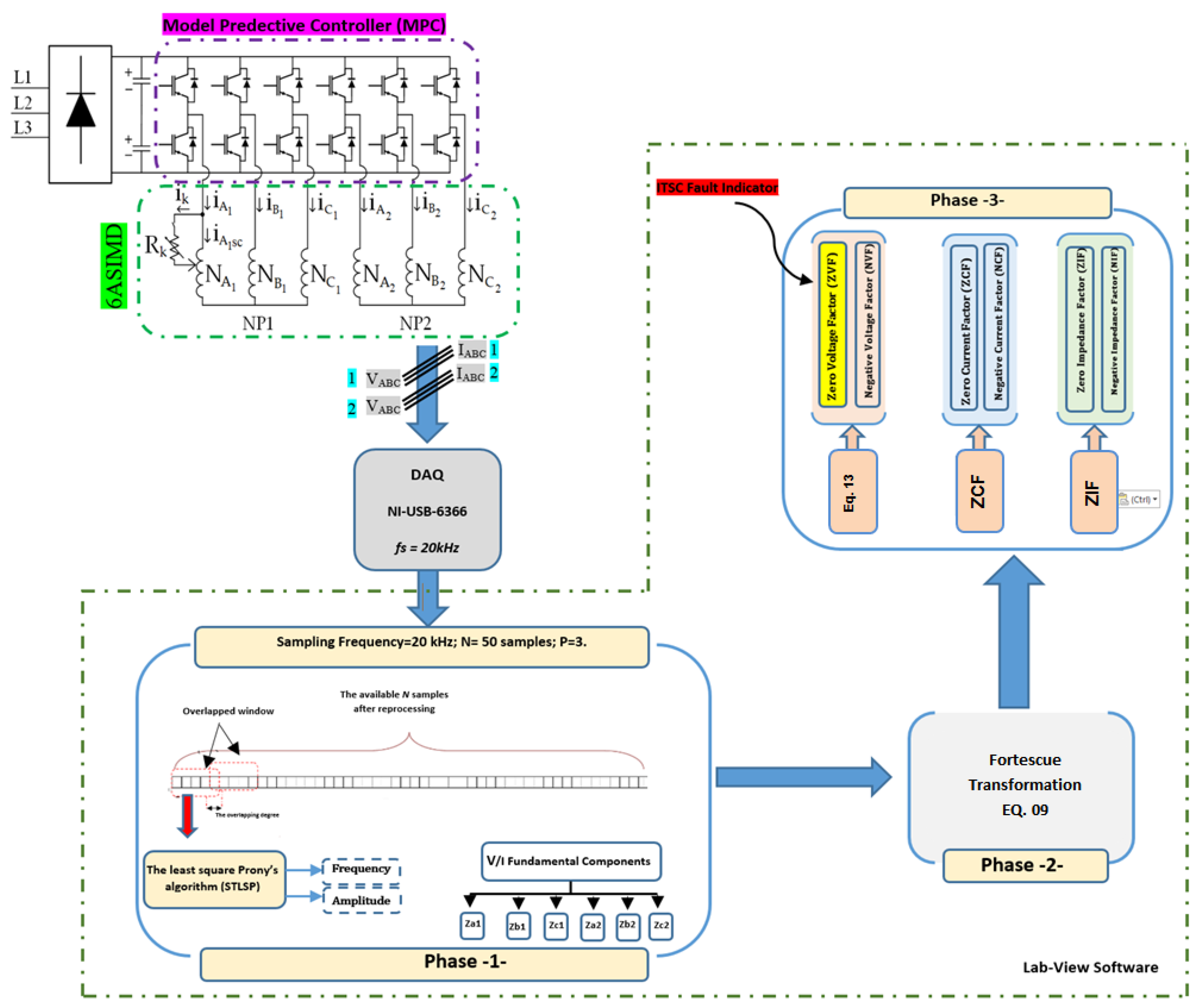
In this context, this study offers a novel approach for online diagnostics of ITSCFs in asymmetrical six-phase induction machines (ASPIMs) based on the aforementioned restrictions. The suggested method, which combines robustness and simplicity, enables efficient diagnosis even under the most difficult circumstances, such as load fluctuations, speed variations, and advanced control. The six-phase stator voltage data are used to calculate the fundamental frequency magnitudes and their related phase angles using the short-time least-square Prony (STLSP) method. At the same time, the Fortescue transformation is used to identify the necessary voltage symmetrical components. The recommended indication is then computed and monitored, going by the name zero voltage factor (ZVF). Thanks to LabVIEW software, each of these steps is completed in real time, permitting online ZVF monitoring for a controlled ASPIM system. To verify the effectiveness of the recommended approach in the context of low- to mid-severity ITSC faults, together with load and speed fluctuations and with various winding connection topologies, numerous experiments were carried out.
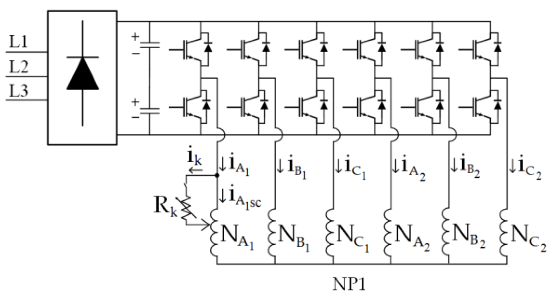
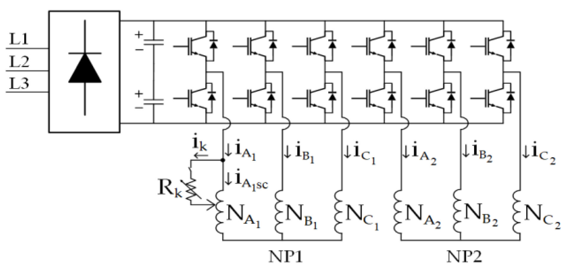
2. Asymmetrical Six-Phase Induction Motor Drives with Single and Dual Isolated Neutral Points
The two three-phase two-level voltage source inverters (2L-VSI) that power the multiphase drive under investigation are coupled to a single dc-link via an ASPIM (see
Figure 1). Two sets of three-phase windings make up the ASPIM (
and
) that are spatially shifted 30 electrical degrees with single (see
Figure 2a) and dual isolated neutral points (see
Figure 2b).
The 2L-VSI provides
different switching states, defined by six switching functions which correspond to the six inverter legs
, where
. The following equation may be used to calculate the stator phase voltages as a function of the dc-link voltage and the aforementioned vector [S]:
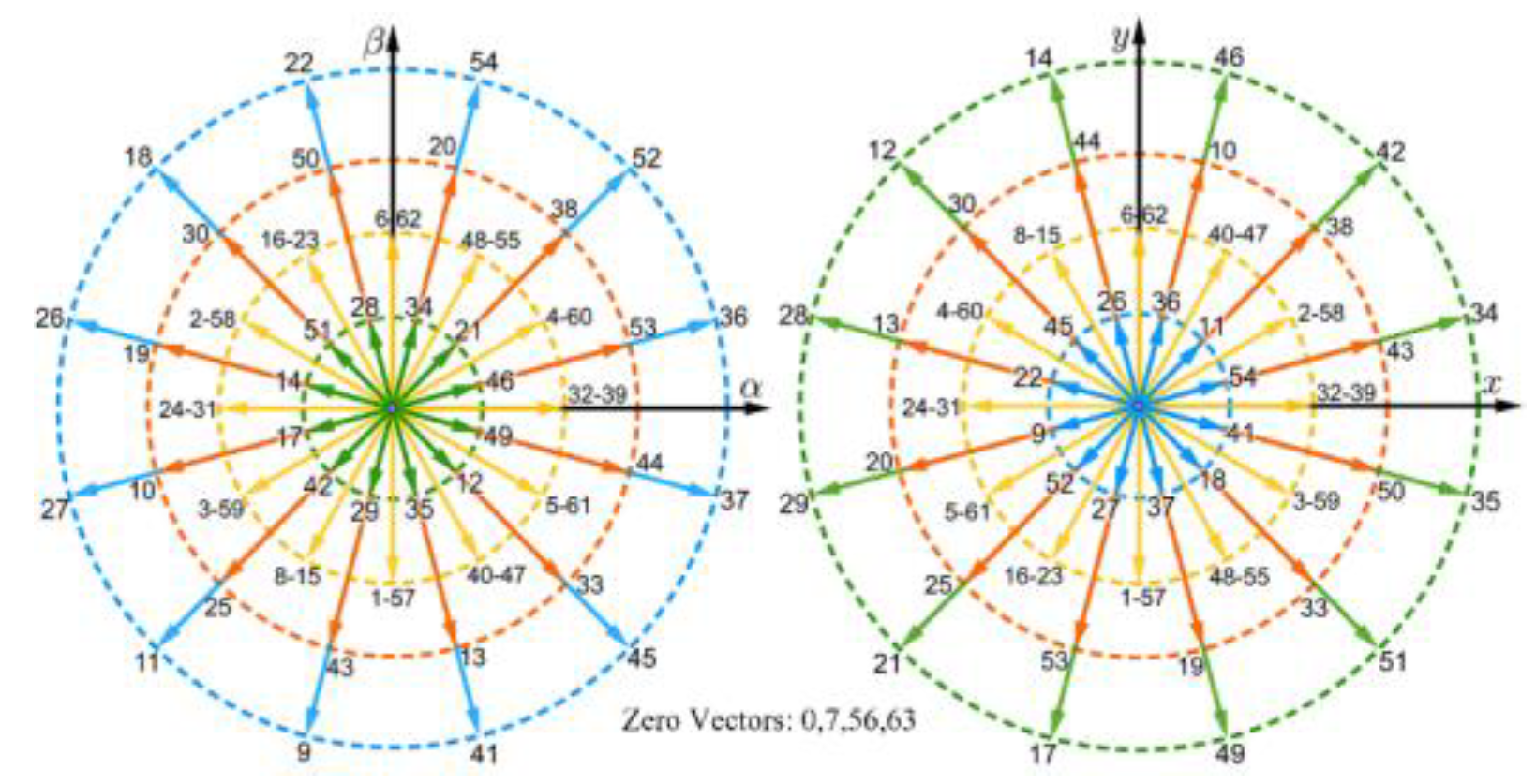
The vector space decomposition (VSD) method, in which phase variables are converted into a stationary reference frame, is one of the most often used options for describing the behavior of the induction machine. In the case of ASPIM, when the VSD is employed, these phase variables are expressed in the (α-β) subspace, which is related to the flux/torque production; the (x-y) subspace associated with the stator copper losses; and the (
) subspace. Using the amplitude-invariant Clarke transformation, the VSD variables may be derived as follows (2):
By applying (2) for each switching state, it is possible to map the 64 control alternatives (48 active and one null voltage vector) depicted in the (α-β) and (x-y) planes as shown in
Figure 3.
Using standard assumptions [
14], the model of this multiphase machine can be had as a state-space representation by employing (3):
where
represent the stator voltages, and
are the currents from the stator and rotor, respectively.
are the resistances of the stator and rotor,
are the phase leakage inductances of stator and rotor,
is the mutual inductance between them, and
is the rotor’s electrical angular speed. The mechanical equations of the ASPIM are specified as (4), (5), and (6):
, , , , , and correspond to the inertia coefficient, friction coefficient, rotor mechanical speed, generated electromagnetic torque, load torque, and number of pole pairs, respectively.
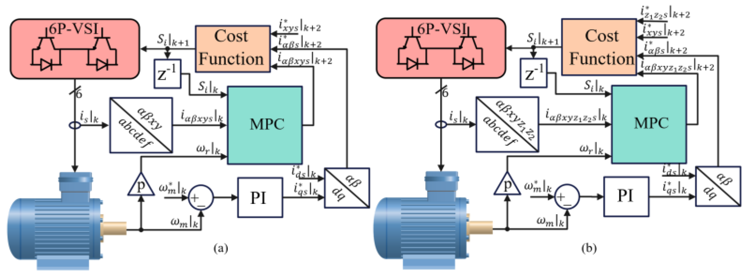
3. Model Predictive Control
Recently, innumerable control schemes have been proposed for high-performance regulation of electric drives. Furthermore, MPC has been one of the most popular control choices in the last decade. One of the motivations for using MPC is to handle constraints on the control inputs and states. Additionally, the MPC has higher overall performance than classic linear controllers [
5]. It is also worth mentioning that the MPC can mask faults because of its predictive characteristics. Therefore, it is essential to study the stator-fault detection in ASPIMs adopting MPC.
In this paper, to obtain the predictive model that estimates the future states of the drive, a forward Euler discretization technique is employed. Then, through an optimization stage, named the cost function, the predicted future states are compared with the respective reference values, and the switching state with the smallest error is selected as the optimal switching state that will be employed in the next sampling period to the 2L-VSIs. For a good control performance, the predictive model relies on the knowledge of the measured parts (stator currents, rotor speed, and stator voltages) and the unmeasurable parts (the rotor variables). In this paper, the method C1a from [
36] is used, where the rotor currents (
) are lumped into one term, designated G, and they are estimated at every sampling period using past values of the measured variables.
Regarding the speed regulation, this task is performed using a PI controller. The d-current () is assumed to be constant and proportional to the rated magnetic flux, whereas the output of the speed controller generates the reference value of the q-current (). Then, the d–q reference currents are transformed into the stationary frame, serving at the control stage to regulate the flux and torque.
In the standard MPC for ASPIM, 49 iterations are performed. Therefore, the cost function (7) is used in the MPC for single neutral point:
where [
,
,
,
] are set to zero. The constants [
,
] represent the weighting factors, and their values must be selected according to the control objectives.
When the dual isolated neutral point configuration is used, the
subspace is neglected because of the isolated-neutral-points design of the ASPIM, so in this configuration, the cost function (8) is used by the MPC:
The voltage vector with the smallest error in or , depending on the configuration, is employed, and will be chosen as the optimal voltage vector and applied to the six-phase inverter during the next sampling.
In summary, he MPC is a machine-model-based high-performance control method for multiphase drives. Due to this, it is parameter-dependent and computationally costly, but it also inherits the benefits of three-phase drives, such as their versatility, simplicity, and quick torque response.
Figure 4 depicts the MPC approach in ASPIM for 1NP (
Figure 4a) and 2NP (
Figure 4b).
5. Experimental Validation
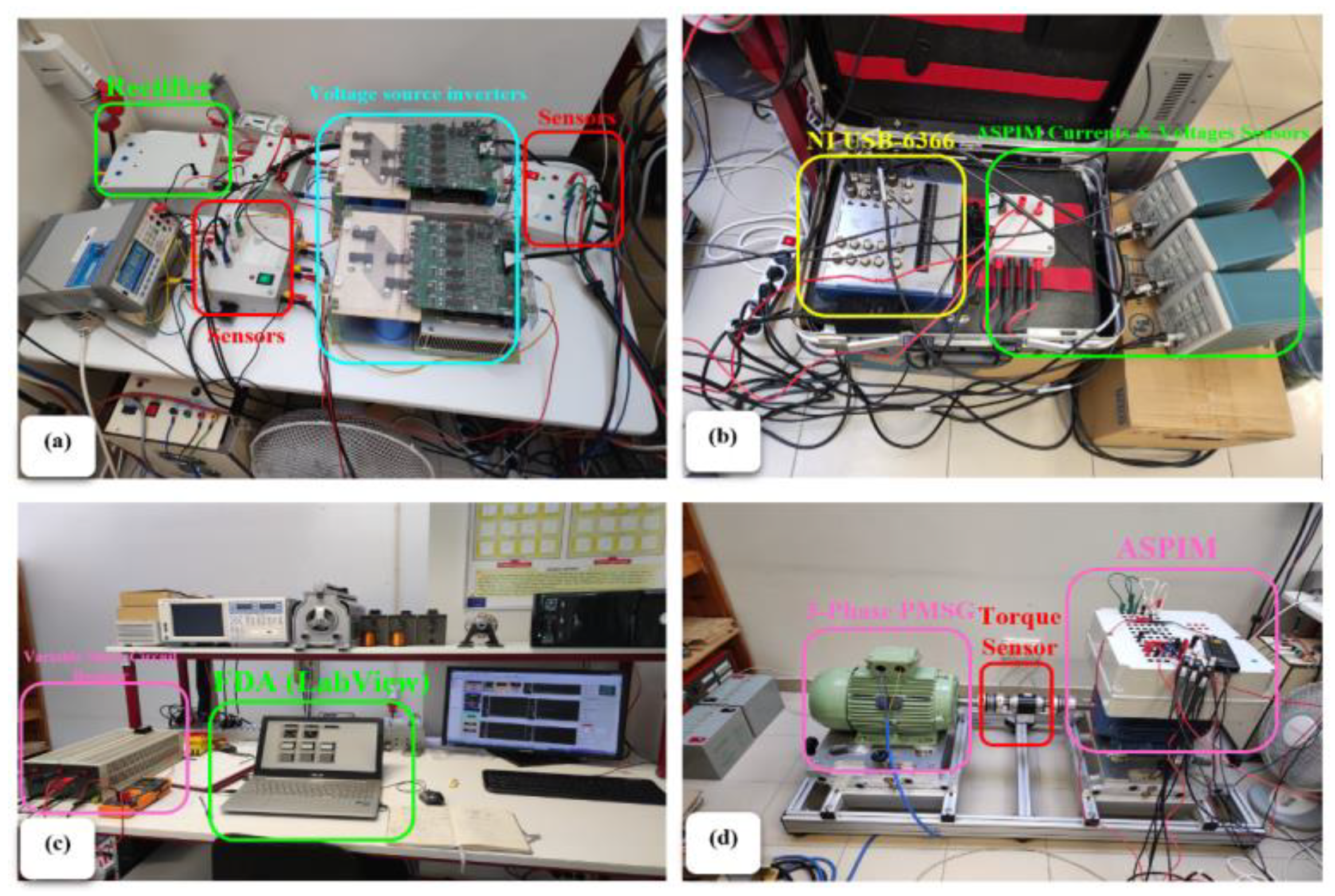
This section examines how the suggested indicators behave under various motor operating scenarios. Testing was performed with the equipment shown schematically in
Figure 7. The performance of the proposed MPC has been experimentally validated. The test bench used for experiments is shown in
Figure 8. It comprises an ASPIM connected to a two-level dual three-phase VSI (Powerex POW-RPAK modules) (
Figure 8a), using a single DC voltage source. The VSI is controlled in real-time by a digital signal processor dSPACE DS1103, with MATLAB/Simulink incorporated. The dSPACE reads and collects data relating to electrical quantities, rotation speed, and torque. The shaft of an AC machine that serves as a generator is coupled to the ASPIM, which is loaded. The power is dissipated via a changeable passive R load coupled to the AC machine; therefore, the load torque is speed-dependent.
Table 1 summarizes the parameters of the ASPIM. The load torque is applied using a PMSG (
Figure 8d), loaded by a three-phase variable resistor.
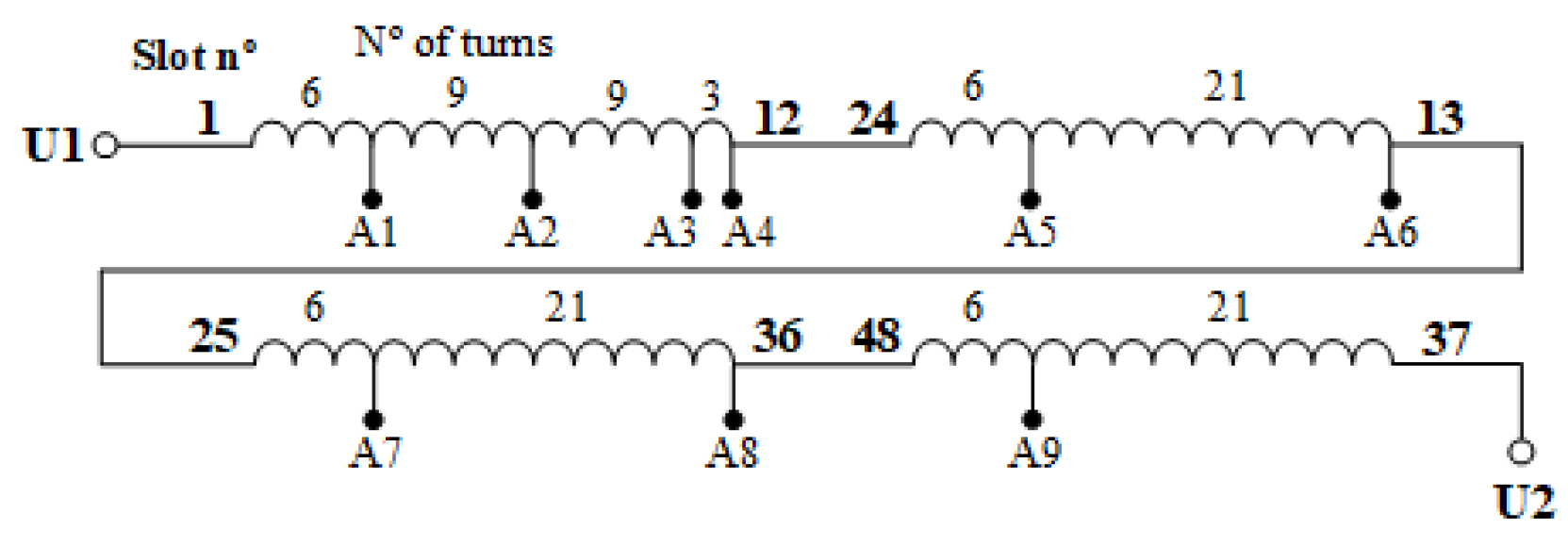
The stator coils and the ASPIM stator windings were connected by tappings. The motor terminal box was linked to the opposing ends of these external wires, letting ITSC defects of various severity be injected at any position of the stator (
Figure 9).
The short-circuited turns were connected in parallel with a fault resistor, , which symbolizes the fault contact resistance. Its value was selected to be both sufficiently low to enable accurate visualization of the fault effect and sufficiently high to maintain the machine’s safety.
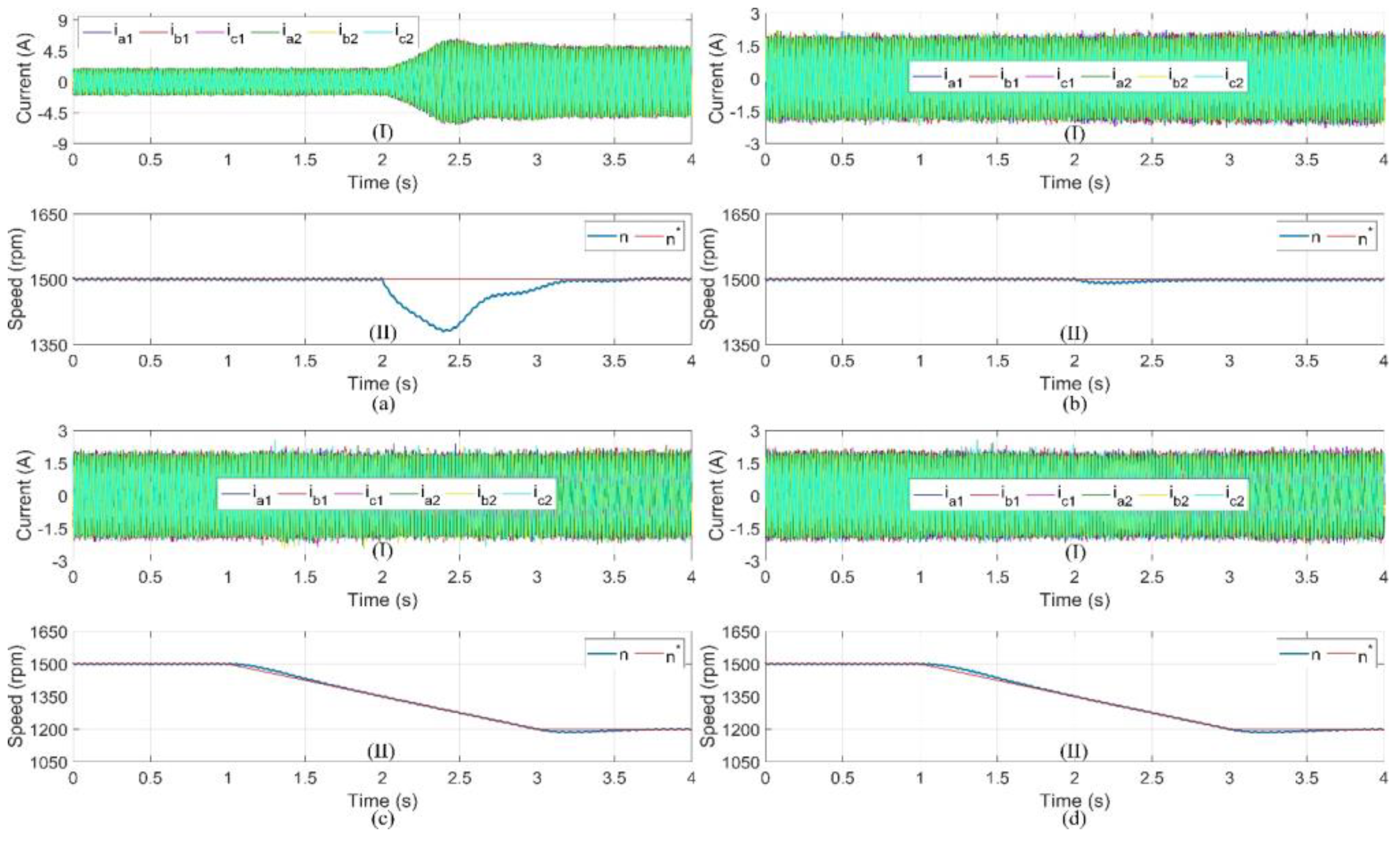
The first part (see
Figure 10) investigated the machine’s performance in a both states, healthy and faulty, with different conditions. In the first condition, we verified the transient state response of the MPC in a healthy state with a transition load torque from 1.5 to 10.6 Nm; see
Figure 10a. In
Figure 10b, the transient-state response in the healthy condition at 1500 rpm with 10.6 Nm is also verified, in the presence of 21 shorted turns at 2 s. In
Figure 10c,d is presented a speed variation from 1500 to 1200 rpm, with a deceleration rate of 150 rpm/s:
Figure 10c shows the healthy condition, and
Figure 10d corresponds to the presence of 21 shorted turns. The speed smoothly tracked its new reference with no significant overshoot for both states, healthy and faulty. It is worth mentioning that there was no effect of 21 shorted turns in the current compared by the load and no effect on speed as well, which confirms the effectiveness of the controller at sustaining the performance of the ASPIM with mechanical perturbation and the presence of stator faults.
The ITSC defect was assessed in the tests for severity with 6, 18, 21, and 24 turns. The STLSP method was used to create the MATLAB code that implements the ZVF indicator computation technique. The LabVIEW program’s implementation of the MATLAB script node may be seen in
Figure 8c above. Filtering, down-sampling, and offset removal were the last procedures, and they were all carried out using Lab-VIEW palettes. Tektronix P5200A differential voltage probes, a Tektronix TCPA300 amplifier, and Tektronix TCP312 current probes were utilized in connection with an NI USB-6366 series data collection board to capture and sample the ASPIM voltages and currents signals at a sampling rate of 20 kHz (
Figure 8b). The ZVF and other important motor characteristics may be effectively screened and tracked online using the endless repetition of these procedures.
The experimental investigation defines three unique performance criteria: robustness against load and speed variations, sensitivity to the kind of topology (with single and dual isolated neutral points), and sensitivity to different fault severity levels.
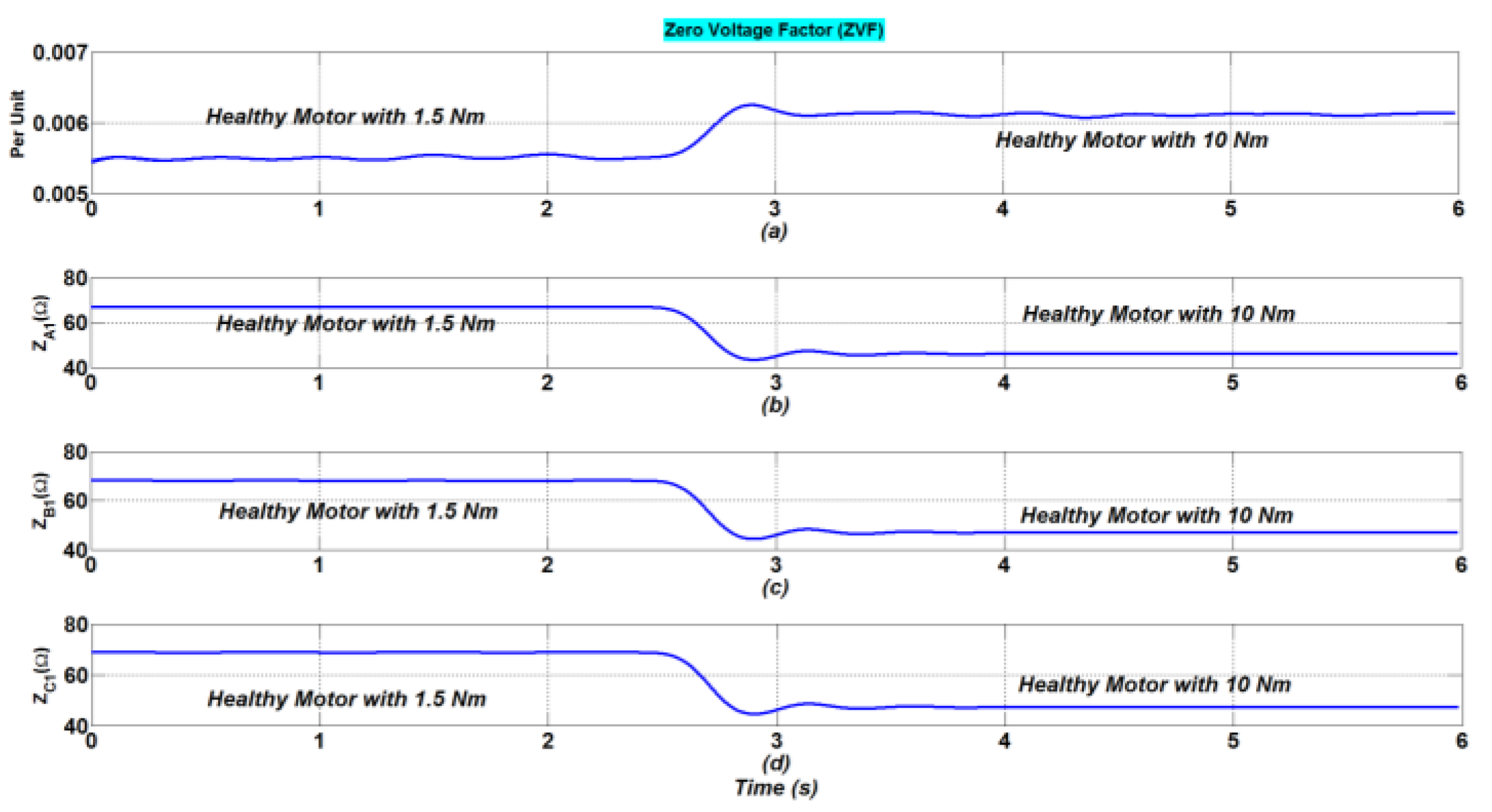
5.1. Robustness of ZVF to Load and Speed Variations
The ASPIM was initially examined in its unloaded, healthy state. The acquisition of the six phase-to-neutral voltages and six phase currents started when the ASPIM was in a healthy state. After a few seconds, a quick load fluctuation was introduced. Indeed, motor load changes are frequent and can appear gradually or abruptly, changing not only the motor currents but also the condition monitoring systems’ fault indicators. Therefore, a trusted fault indicator must reflect insensibility to load changes and speed variations. Several experiments were conducted to see how the stated characteristics responded to modifications in the step load (from 1.5 to 10 Nm) and speed (from 1500 to 1200 rpm). The time-domain waveforms of the motor currents are affected by step-load variations (see
Figure 10a), resulting in non-stationary signals with severe distortion (see
Figure 11).
The adopted technique allows the use of the STLSP technique, which has shown to be appropriate for highly dynamic operating scenarios [
35], as it precisely computes and tracks the indicators defined in (16) while requiring the least amount of data samples (50 data samples).
Figure 11 and
Figure 12 show, respectively, how the ZVF indicators and impedances have changed as a result of changes in step load and speed.
Referring to Figures, there are clear variations in the impedances of the first three phase systems, resulting from the load transient and speed variation. As was already noted, mechanical disturbances such as speed variations and load transients were present during the experimental experiments. In fact, smooth or quick load disturbances may have a direct impact on motor characteristics such as voltages and currents, which raises the possibility that some fault indicators’ performances may be adversely impacted. The performance of the ZVF under a progressive load fluctuation and a randomly applied speed variation was examined in experimental tests. The suggested fault indication is unaffected by variations in the load torque and speed fluctuation, indicating potential properties for fault diagnosis.
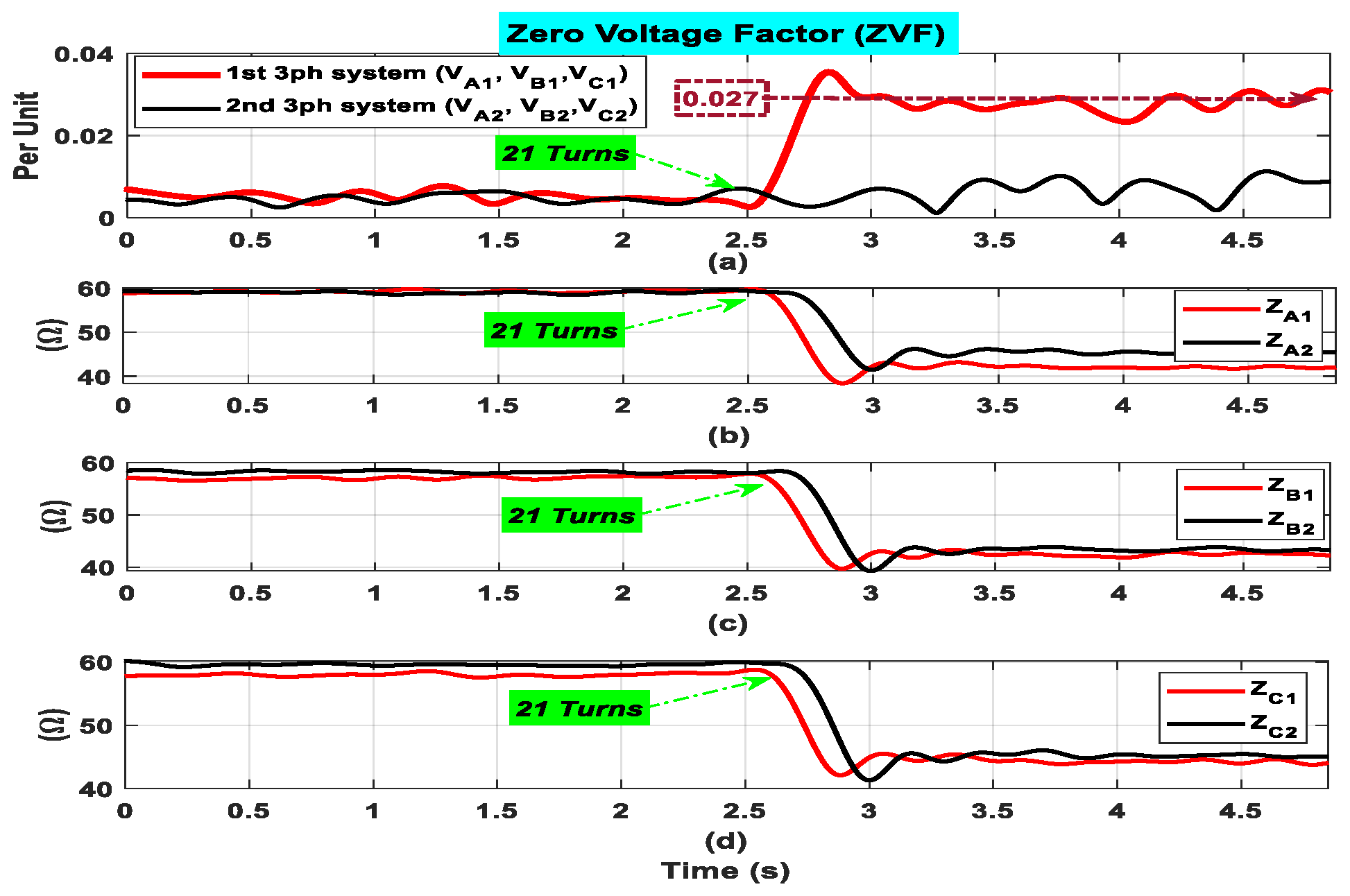
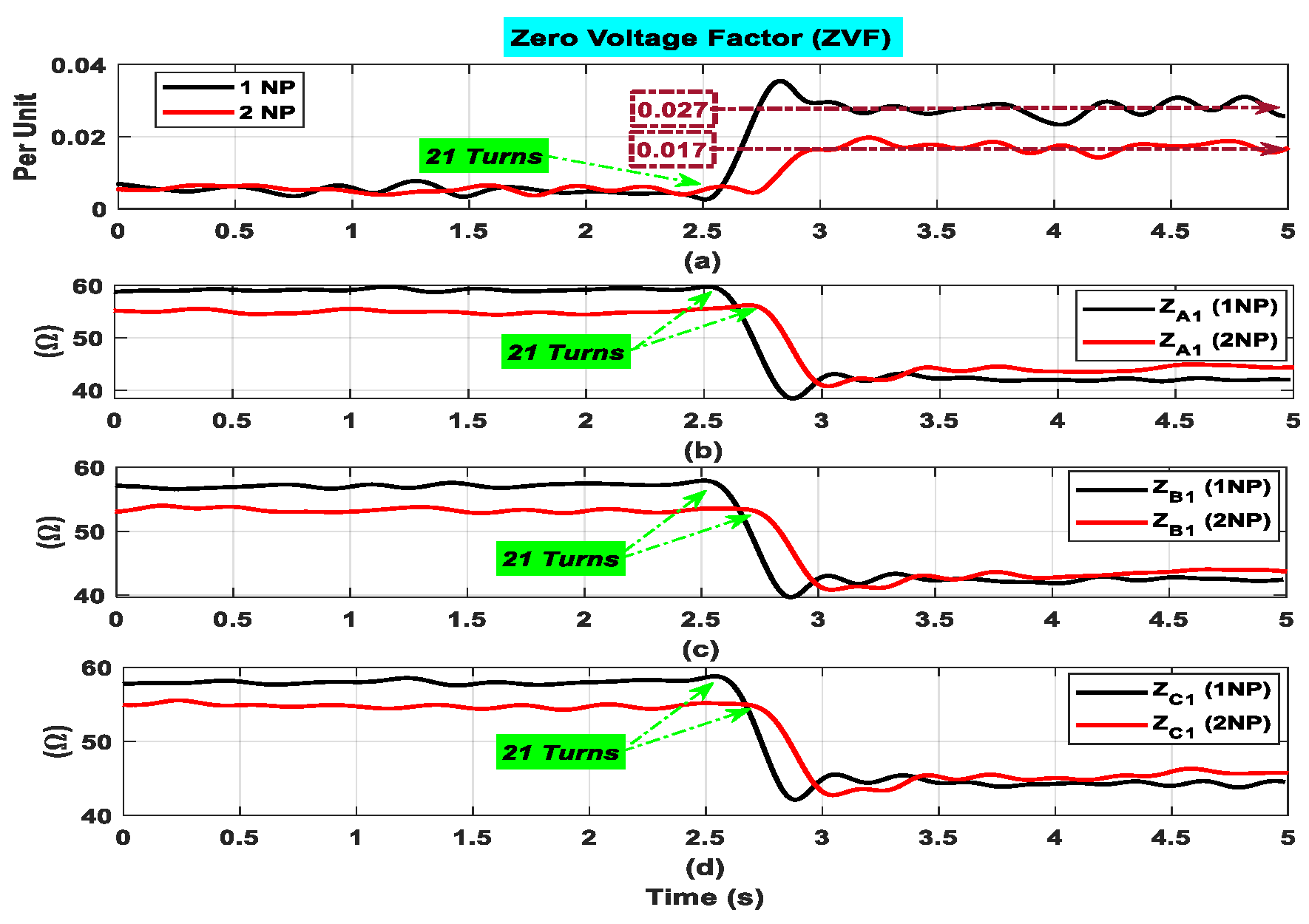
5.2. Robustness of ZVF to Different Stator topologies (Single and Dual Isolated Neutral Points)
Figure 13 shows the suggested indicator’s time-domain evolution (ZVF
A1B1C1 and ZVF
A2B2C2). This curve offers a solid physical interpretation of the ITSC defect, as is evident. In reality, the ZVF evolution displays steady values with tiny amplitudes when the motor is operating in the healthy mode (verified due to the motor inherent asymmetries). The indication goes up to significantly higher values after a minor ITSC defect is added, which is in excellent accordance with the prior mathematical evidence. In fact,
Figure 14 shows that ZVF
A1B1C1 increases noticeably and quickly (less than 0.2 s), from 0.005 p.u. to 0.027 p.u., or a 440% increase. In addition,
Figure 14 shows that ZVF
A2B2C2 almost did not change. The qualitative (
Figure 13) and quantitative (
Table 2) results unequivocally show that when an ITSC fault occurs, the suggested fault indicator changes in a predictable and significant way. This is highly helpful for identifying low severity stator defects, which could go unnoticed by the majority of cutting-edge techniques.
One of the most important goals of this work is to prove the effectiveness of the proposed indicators taken into consideration for different topologies of the stator (with single and dual isolated neutral points).
Figure 14 shows the suggested indicator’s time-domain evolution and the impedances, respectively. This curve offers a solid physical interpretation of the ITSC defect, as is evident. In fact, with dual neutral point (2NP) topology, the ZVF increases noticeably and quickly, from 0.005 to 0.027 p.u., or a 440% increase. In addition, with a single neutral point (1NP), the ZVF increases significantly, from 0.005 to 0.017 p.u., an increase of 240%—almost the half of the value of 2NP. The findings, both quantitative (
Table 3) and qualitative (
Figure 14), unequivocally show that when an ITSC fault occurs, the suggested fault indicator changes in a predictable and significant way. On the contrary, the proposed indicator (ZVF) gives better results with the dual isolated neutral point topology (2NP). In addition, the time-domain evolution of the estimated phase impedances is provided in
Figure 14b–d. Under healthy conditions, after introducing the ITSC fault, all three phase impedances decrease proportionally to the severity of the fault. The observation of similar decrement in all phases can be explained by the adoption of advanced control, and there is no effect of the type of stator topology (1NP or 2NP).
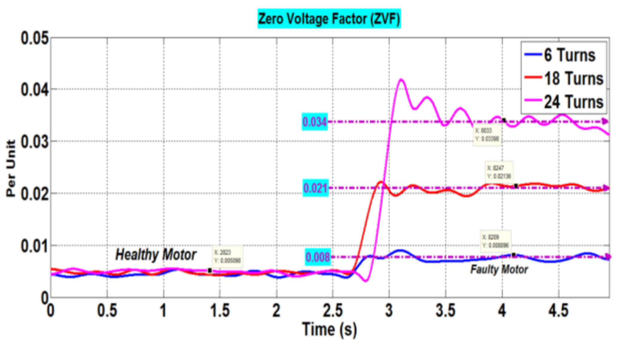
5.3. Robustness of ZVF to Various ITSCF Severities
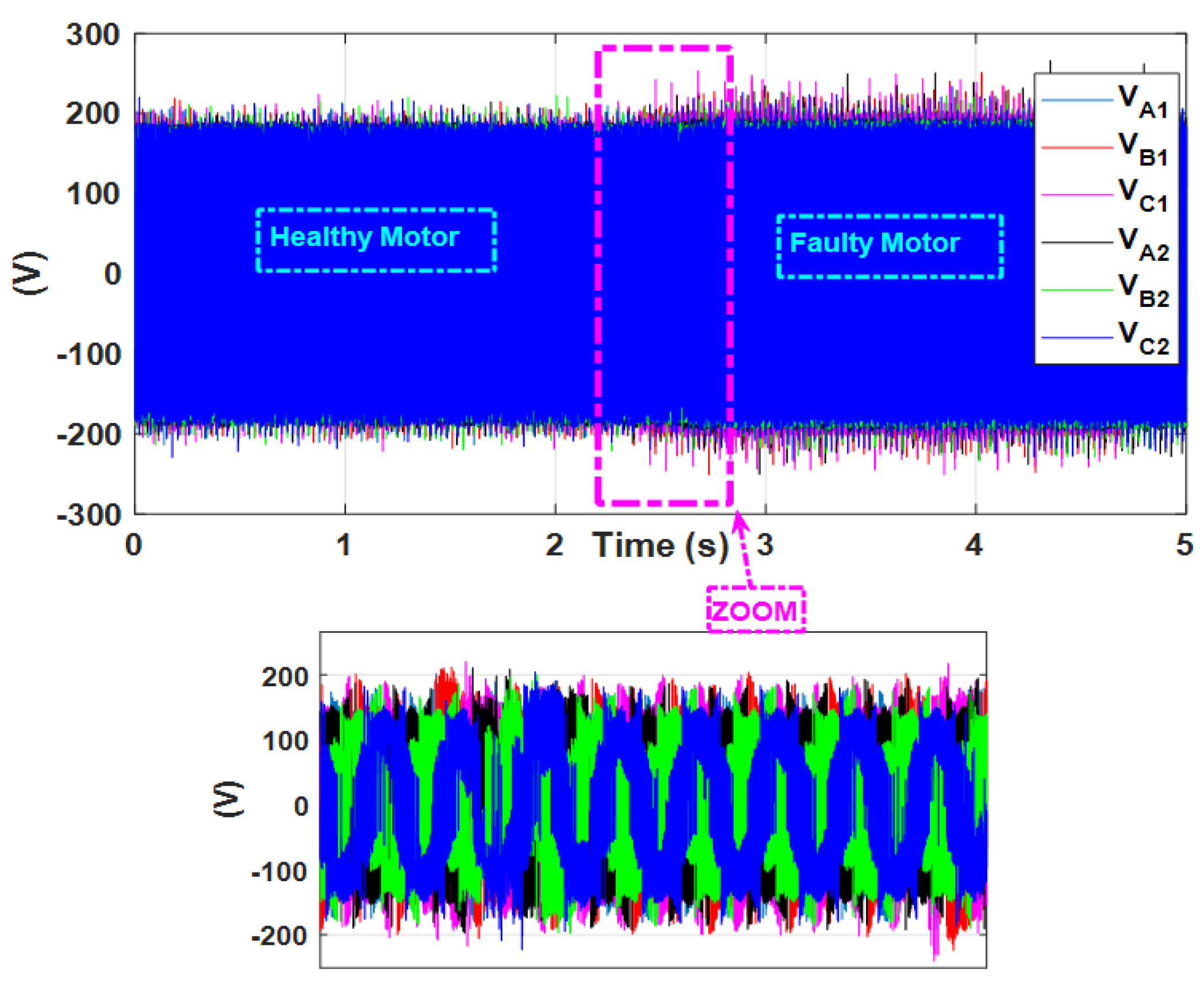
The proposed indication, ZVF, for the first three-phase system, was initially tested by operating the ASPIM in a healthy state with no load. ASIM was in a healthy state when the acquisition of voltages and currents started. After a short period, phase-a stator revolutions were abruptly shorted. After a sudden ITSCF in phase-a,
Figure 15 shows the time-domain development of the phase-to-neutral voltages. Different fault severity levels were taken into account by varying the number of shorted turns.
Figure 16 shows the suggested indicator ZVF’s temporal evolution. An accurate explanation of the ITSCF is provided by the ZVF curve for the ITSCF with the lowest severity (06 turns). The trajectory of ZVF provides low, sustained amplitude measurements when the motor is operating in a healthy mode; these oscillations are confirmed by the underlying asymmetries of the motor. The indicator increases to significantly higher levels once a small ITSCF is present, which is in excellent accord with the previous mathematical evidence. In fact,
Figure 16 shows that the ZVF increases significantly from 0.005 to 0.008 p.u., or a 60% increase, with a very quick response (less than 0.2 s). The qualitative and quantitative results unequivocally show that when an ITSCF occurs, the proposed fault indicator changes in a predictable and significant way. This characteristic is highly helpful for both enabling efficient diagnostics in complex regulated systems and identifying low-severity stator problems, which are often missed by state-of-the-art methods.
ITSCFs can have different degrees of severity. The recommended indicator must thus pass stringent tests, including those that assess its stability and its clear reaction to sequential and discrete fault levels. In this laboratory experiment, the ASPIM was started in healthy circumstances with no load. In a short period of time, increasingly severe ITSC faults were introduced. Phase-a was then completed by shorting turns 6, 18, and 24. This process involved real-time computation and monitoring of the ZVF. While
Figure 16 shows the indicator’s time-domain evolution,
Table 4 gives a precise evaluation of the studied indication by displaying the amount of change as a function of the number of shorted turns.
It is clear that the ZVF exhibits consistent and modest amplitudes during the motor’s operation in a healthy condition. On the other hand, the ZVF reacts instantly to the presence of 06, 18, and 24 shorted turns. In fact, this indicator rose noticeably from 0.008 to 0.021 and 0.034, respectively, reflecting increases of 60%, 320%, and 580%. This pattern shows a clear response of the ZVF to the ITSCF condition, as its amplitude grows as the fault’s severity rises. This is a significant outcome, since it shows how well the suggested indicator can both identify an impending ITSCF and measure the fault’s severity, even in regulated systems.


