Article

Anti-Rollover Control and HIL Verification for an Independently Driven Heavy Vehicle Based on Improved LTR

1
Department of Mechanical Engineering, Shijiazhuang Tiedao University, Shijiazhuang 050043, China
2
State Key Laboratory of Mechanical Behavior in Traffic Engineering Structure and System Safety, Shijiazhuang Tiedao University, Shijiazhuang 050043, China
3
School of Mechanics and Engineering Science, Shanghai University, Shanghai 200444, China
*
Author to whom correspondence should be addressed.
Machines 2023, 11(1), 117; https://doi.org/10.3390/machines11010117
Submission received: 16 December 2022 / Revised: 10 January 2023 / Accepted: 12 January 2023 / Published: 14 January 2023
(This article belongs to the Special Issue Advanced Modeling, Analysis and Control for Electrified Vehicles)

Abstract

:
The rollover evaluation index provides an important threshold basis for the anti-rollover control system of vehicle. Regarding the rollover risk of independently driven heavy-duty vehicles, a new rollover evaluation index is proposed, and the feasibility of the improved index was verified through hierarchical control and HIL (hardware-in-the-loop) experiments. Based on an 18-DOF spatial dynamics model of a heavy-duty vehicle, the improved LTR (load transfer rate) index was obtained to describe the dynamic change in the tire’s vertical load. It replaces the suspension force and the vertical inertia force of the unsprung load mass. It avoids the problem of directly measuring or estimating the vertical load in the LTR index. Under the conditions of fishhooking and angle stepping, three types of rollover indicators were compared, and the proposed index can more sensitively identify the likelihood of rollover. In order to apply the improved rollover index to a rollover control well, a hierarchical controller based on the identification of the slip rate of the road surface, ABS control with sliding mode, variable structure and differential braking was designed. Simulations and HIL tests proved that the designed controller can accurately predict the rollover risk and avoid the rollover in time. Under the condition of J-turning, the yaw rate, slip angle and maximum lateral acceleration are reduced by 9%, 16% and 3%, respectively; under the condition of fishhooking, the maximum yaw rate, slip angle and lateral acceleration are reduced by 12%, 18% and 3%, respectively.

1. Introduction

Vehicle rollover is an extreme condition of transient vehicle instability. Although rollover accidents account for a small proportion of all traffic accidents, once they occur, they cause large numbers of deaths and injuries. According to the National Highway Traffic Safety Administration (NHTSA) [1], more than 6 million traffic accidents occurred in 2016. Although only 486,100 rollovers occurred, 17.9% of fatal accidents were caused by vehicle rollovers, and buses and heavy vehicles accounted for 47.5% of fatal accidents. Heavy-duty vehicles have the characteristics of large mass and a high center of mass. The centrifugal force and roll moment generated during steering are larger than those of other vehicles, making them more prone to rollover accidents [2,3]. Heavy-duty vehicles are mainly used for long-distance cargo transportation. Once a rollover accident occurs, it often brings significant casualties and high economic losses. Therefore, anti-rollover is critical to vehicle dynamics and active safety.
Rollover accidents can be divided into two types: untripped and tripped rollovers. In order to accurately describe different types of rollover motion, it is necessary to establish an accurate dynamic model of rollover. Untripped rollover is mainly due to emergency avoidance steering and improper driver operation. For the untripped vehicle model, scholars mainly analyze the various degrees of freedom (DOF) of the vehicle itself. For example, Doumiati (2013) [4] simplified the vehicle into a linear vehicle to maintain good stability, and designed the LPV controller based on a 2-DOF model. In order to realize the rollover prediction of heavy vehicles, Ye (2020) [5] established a 3-DOF model and calculated the critical frequency of rollover. Huang (2019) [6] established a 7-DOF vehicle model to improve vehicle stability. Tripped rollover is mainly caused by external interference, such as road slope and excitation. Therefore, when establishing a stumbling rollover model, scholars need to consider the influences of external factors. For example, in order to improve the anti-rollover ability of vehicles on uneven roads, Jin Zhilin (2018) [7] established an 8-DOF rollover model considering the characteristics of wheel independent rotation and proposed a hierarchical controller including roll-angle sliding-mode control. In order to verify the effect of the controller, Shi (2018) [8] established an 8-DOF vehicle model. Zhang et al. (2022) [9] established a 14-DOF space vehicle model and proposed a cooperative control method for space stability, including four-wheel differential drive and front-wheel active steering to improve vehicle space stability. At the same time, considering the characteristics of heaviness and a high center of mass possessed by heavy vehicles, some scholars established a rollover model for heavy vehicles [10,11,12,13,14,15,16,17,18,19,20]. Therefore, scholars can establish corresponding rollover models according to the focuses of their research. An accurate and reasonable rollover dynamics model provides an important basis for the implementation of precise anti-rollover control.
In order to avoid vehicle rollover, a detection technique is needed to estimate the possibility of vehicle rollover. The rollover evaluation index or rollover threshold determines the timing of the triggering of rollover control. An appropriate rollover evaluation index is the core of creating an anti-rollover controller. The lateral load transfer rate (LTR) is a commonly used rollover evaluation index [21,22,23]. However, the vertical force of each tire in this index is not easy to measure, so many scholars convert the LTR into easy-to-measure parameters to further represent the rollover evaluation index. Odenthal (1999) [24] integrated lateral acceleration into LTR and used lateral acceleration and a roll angle to describe the rollover evaluation index RI2 and verified its accuracy. Phanomchoeng (2013) [25] considered the vertical motion on both sides of the unsprung part and deduced the rollover index considering the external input; Dahmani (2015) [26] analyzed the roll motion of the vehicle and converted the LTR into an indicator expressed by the roll angle to assess the risk of vehicle rollover. Considering the influence of road excitation on vehicle rollover, Jin (2016) [27,28] transformed the LTR into an index called RI, including the vertical acceleration of sprung and unsprung. ATAEI [29] converted the LTR into a rollover index represented by roll stiffness and damping, and proposed a predictive control strategy to solve the vehicle rollover problem more effectively. Zhao [30] transformed the LTR to an index that depends on the unsprung mass height and the unsprung mass. In summary, at present, the judgment condition of whether the vehicle will rollover is mainly based on the load condition of the tire. Shin derived a rollover evaluation index for commercial vehicles [31]. Judging whether the tire is in contact with the ground, due to the particularities of the heavy vehicle itself, is particularly important to predicting rollover. The existing LTR-based evaluation indexes are mostly improved by combining a suspension model and a small vehicle model, while ignoring the influences of longitudinal acceleration and unsprung vertical acceleration on vehicles. They are mostly suitable for rollover evaluations of small commercial vehicles. Therefore, it is necessary to establish an evaluation index which can accurately estimate the rollover risk of heavy vehicles.
With the widespread application of multi-axle distributed wheel-driven heavy-duty vehicles and the development of advanced control technology, active control has been widely used in the design of anti-rollover control systems in the automotive industry. At present, in active anti-rollover control, differential braking can be fully used to control the transient instability of the vehicle [32]. In order to ensure the lateral stability of three-axle vehicles, LIU (2017) [33] designed an integrated chassis control strategy including differential braking. In order to reduce the oscillation of vehicle lateral response parameters under extreme conditions, Soltani (2018) [34] proposed a comprehensive control method based on differential braking. Dong (2019) [35] developed a vehicle anti-rollover control system based on differential braking. In order to improve vehicle maneuverability and safety, Termous (2019) [36] proposed a coordinated control strategy that includes differential braking. In order to improve the roll stability of the distributed drive tram, Chang (2022) [37] designed a control strategy based on differential braking. Zang (2022) [38] carried out differential braking control on a vehicle under extreme conditions, and effectively controlled the lateral stability of the vehicle. Wang [39] proposed a differential braking control scheme based on tire-force-distribution rules. Some scholars have studied the anti-rollover control of vehicles by using sliding-mode control or a multi-control fusion strategy [40,41,42,43,44]. These studies provide the ability to solve the rollover control problem of heavy vehicles at the bottom layer. In addition, it is necessary to take into account the characteristics of heavy vehicles, such as large unsprung mass and high center of mass. In order to ensure the accuracy and timeliness of the heavy vehicle’s state variables in the upper control, the evolution of vehicle dynamic performance and the dynamic capturing of the rollover threshold should be combined.
In order to verify the effectiveness of the anti-rollover control strategy, scholars use simulations or HIL testing to verify. In terms of HIL experiments, most of them are aimed at small vehicle models [45,46,47,48], and there have been few real-vehicle experiments on differential braking control of heavy vehicles. Therefore, after building the anti-rollover control strategy of heavy vehicles, it is necessary to carry out HIL tests for heavy vehicles to ensure the effectiveness of the control strategy.
To solve the rollover problem of a three-axle distributed-hub-driven heavy-duty vehicle, the structure of this paper is as follows: In Section 2, a complete three-axle heavy-duty vehicle’s spatial dynamics model is established. Based on LTR, an improved rollover evaluation index is proposed. The derivation process of the improved rollover index is introduced, and the feasibility and real-time performance of the improved LTR is fully demonstrated. In Section 3, the overall structure based on the improved LTR anti-rollover control strategy is described. The optimal slip rate identification is introduced. The braking model of anti-lock braking system based on sliding-mode variable structure is established. The control logic of differential braking is described. In Section 4, we report the testing of a heavy vehicle by Trucksim/simulink co-simulation to verify the control effect of the anti-rollover predictive control algorithm based on the improved LTR. In Section 5, the anti-rollover algorithm under the two conditions of fishhooking and angle stepping is analyzed according to a hardware-in-the-loop (HIL) test, and the experimental results are analyzed. In Section 6, the above contents are summarized, and the future research direction is put forward.

2. Heavy-Vehicle-Dynamics Model
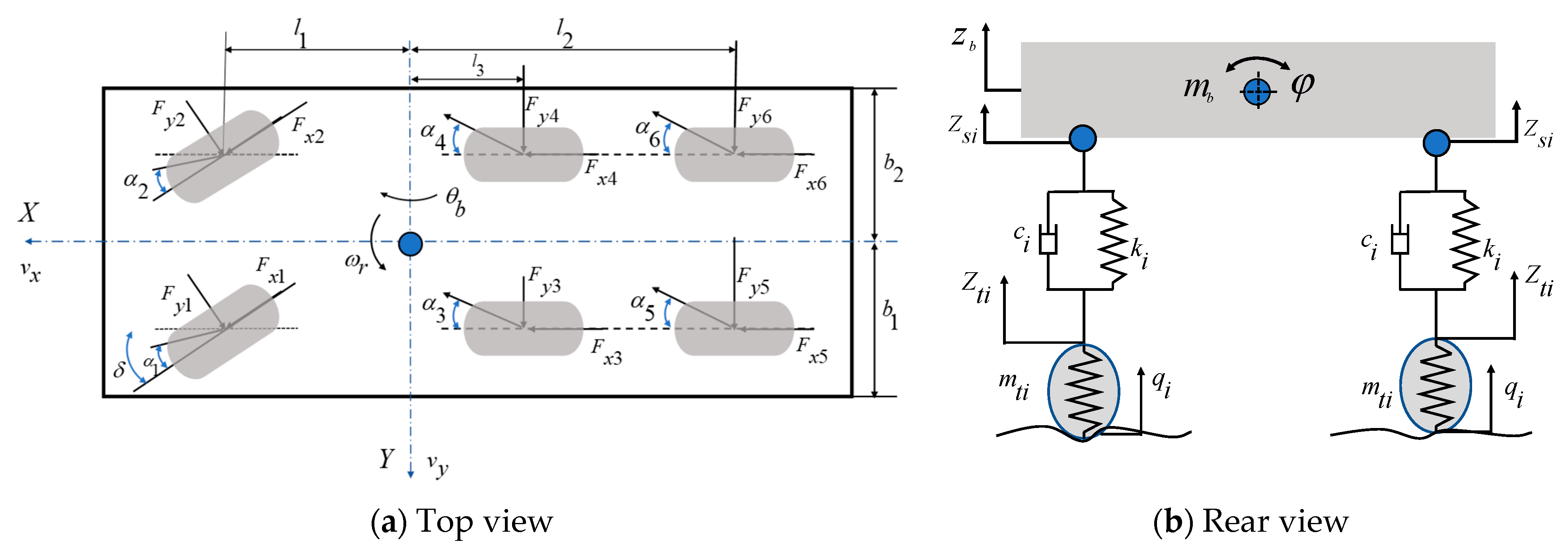
In order to derive the evaluation index of vehicle rollover, it is necessary to first build a vehicle-dynamics model, and then integrate the vehicle-dynamics model into LTR to derive the new evaluation index.

2.1. Vehicle Model

Firstly, an 18-DOF spatial dynamics model is established, including vehicle longitudinal, lateral and vertical motion, body pitch, roll and yaw, wheel rotation and vertical motion. The model is shown in Figure 1.
In Figure 1, v x and v y denote the longitudinal and lateral vehicle speeds, respectively; θ b , φ and ω r are the body pitch angle, lateral tilt angle and transverse angular velocity, respectively; m b , z b are the spring-loaded mass and body vertical displacement, respectively; l 1 , l 2 and l 3 are the distances from the center of mass to the front, middle and rear axes, respectively; b 1 and b 2 are the distances from the left and right-sides of the vehicle to the center axis, respectively; m t i , F x i and F y i are the tire masses and the longitudinal and lateral forces on the tires, respectively; and the subscripts i = 1 ~ 6 indicate the left front, right front, left center, right center, left rear and right rear, respectively. Right-center, left-rear and right-rear are the same below. z s i , q i and α i are the suspension displacement, the input of road unevenness and the tire’s lateral deflection angle, respectively; c i , k i and f a i are the suspension stiffness, damping and active suspension force, respectively; δ is the front-wheel rotation angle; h is the center of mass height.
The expression for the displacement of contact part of suspension and vehicle is Equation (1).
{ z s 1 = z b θ b l 1 + φ b 1 z s 2 = z b θ b l 1 φ b 2 z s 3 = z b + θ b l 2 + φ b 1 z s 4 = z b + θ b l 2 φ b 2 z s 5 = z b + θ b l 3 + φ b 1 z s 6 = z b + θ b l 3 φ b 2
The suspension force can be expressed as Equation (2).
f s i = k i ( z s i z t i ) + c i ( z ˙ s i z ˙ t i ) ,
where f s i is the suspension force.
Based on D’Alembert’s principle, the whole vehicle dynamics Equation (3) is established.
{ m z ( v ˙ y + v x ω r ) m b z ˙ b φ ˙ m b h φ ¨ = i = 1 2 ( F y i cos δ + F x i sin δ ) + i = 3 6 F y i m z ( v ˙ x v y ω r ) + m b z ˙ b θ ˙ b = i = 1 2 ( F x i cos δ + F y i sin δ ) + i = 3 6 F x i m b ( z ¨ b v x θ ˙ b + v y φ ˙ ) = i = 1 6 f s i I y θ ¨ b = l 1 i = 1 2 f s i l 2 i = 3 4 f s i l 3 i = 5 6 f s i I z ω ˙ r + I x z φ ¨ = l 1 i = 1 2 ( F y i cos δ + F x i sin δ ) l 2 i = 3 4 F y i l 3 i = 5 6 F y i + B / 2 [ ( F x 2 F x 1 ) cos δ + ( F y 2 F y 1 ) sin δ + F x 3 F x 4 + F x 5 F x 6 ] ( I x + m b h 2 ) φ ¨ m b h a y = b 1 ( f s 1 + f s 3 + f s 5 ) + b 2 ( f s 2 + f s 4 + f s 6 ) + M T I i ω ˙ i = F x i R i T b i ,
where I x , I y , I z and I x z are the rotational inertia around x, y and z axes, and the xz plane, respectively; m z is the vehicle mass; k t i is the tire stiffness; B is the body width; I i is the wheel rotational inertia; ω i is the wheel speed; R i is the wheel radius; T b i is the braking moment; M T is the sway moment.
The equation for the unsprung mass vertical dynamics is Equation (4).
m t i z ¨ t i = f s i k t i ( z t i q i ) ,
The vertical dynamic load of the wheel consists of the static load of the tire and the dynamic load, and the vertical force of each wheel is expressed as Equation (5):
{ F z 1 = m b g B / 2 h sin φ B m b a y h cos φ B m b a x h cos φ B / 2 + h sin φ B + k t 1 ( z t 1 q 1 ) F z 2 = m b g B / 2 + h sin φ B + m b a y h cos φ B m b a x h cos φ B / 2 + h sin φ B + k t 2 ( z t 2 q 2 ) F z 3 = m b g B / 2 h sin φ B m b a y h cos φ B + m b a x h cos φ B / 2 + h sin φ B + k t 3 ( z t 3 q 3 ) F z 4 = m b g B / 2 + h sin φ B + m b a y h cos φ B + m b a x h cos φ B / 2 + h sin φ B + k t 4 ( z t 4 q 4 ) F z 5 = m b g B / 2 h sin φ B m b a y h cos φ B + m b a x h cos φ B / 2 + h sin φ B + k t 5 ( z t 5 q 5 ) F z 6 = m b g B / 2 + h sin φ B + m b a y h cos φ B + m b a x h cos φ B / 2 + h sin φ B + k t 6 ( z t 6 q 6 ) ,
where a x and a y are the longitudinal and lateral acceleration of the vehicle, respectively; F z i is the dynamic load of each wheel in the vertical direction.

2.2. Tire Model

The “magic formula” tire model is used, and the longitudinal and lateral forces are shown in Equation (6) [49].
F ( x ) = D sin ( C arctan [ B x E ( B x arctan B x ) ] ) ,
where F ( x ) is the longitudinal force or lateral force on the tire. x is the tire slip rate or lateral deflection angle. B , C , D and E are the fitting parameters. The value of each parameter is given in a paper produced by this group [50].
The lateral deflection angle of the tire is expressed in Equation (7).
{ α 1 = α 2 = arctan [ ( v y + l 1 ω r ) / v x ] δ α 3 = α 4 = arctan [ ( v y l 2 ω r ) / v x ] α 5 = α 6 = arctan [ ( v y l 3 ω r ) / v x ]

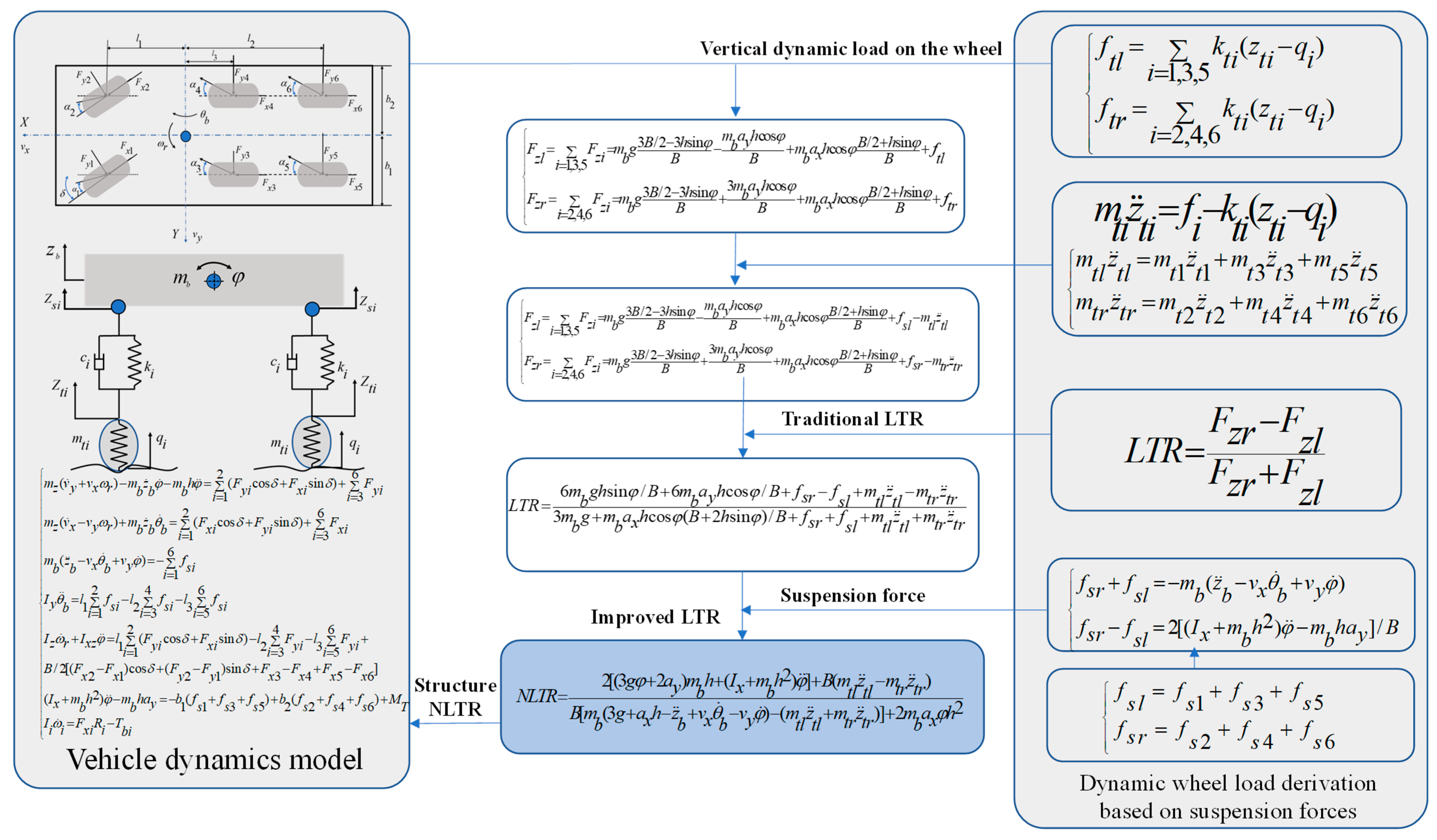
2.3. Improving LTR Rollover Indicators

The vehicle-rollover evaluation index’s transverse load transfer rate [8] is Equation (8).
L T R = F z r F z l F z r + F z l ,
where F z l and F z r are the left and right-side vertical forces of the wheels, respectively, and since the vertical forces on the wheel are not easily measured directly, the whole vehicle-dynamics model can be brought into Equation (8) for further derivation to obtain the measurable rollover index for each parameter.
To ensure the simplicity of the subsequent derivation process, the left and right-side suspension forces, left and right-side unsprung mass droop dynamics and left and right-side wheel droop loads are defined by combining Equations (2), (4) and (5). The left and right-side suspension forces are shown in Equation (9).
{ f s l = f s 1 + f s 3 + f s 5 f s r = f s 2 + f s 4 + f s 6
where f s l and f s r are the left and right-side suspension forces, respectively. The left and right-side unsprung mass vertical motions are redescribed in Equation (10), respectively.
{ m t l z ¨ t l = m t 1 z ¨ t 1 + m t 3 z ¨ t 3 + m t 5 z ¨ t 5 m t r z ¨ t r = m t 2 z ¨ t 2 + m t 4 z ¨ t 4 + m t 6 z ¨ t 6 ,
where m t l , m t r , z ¨ t l and z ¨ t r are the left and right-side unsprung masses and their vertical accelerations, respectively. The sums of the vertical forces on the left and right wheels are redescribed in Equation (11).
{ f t l = i = 1 , 3 , 5 k t i ( z t i q i ) f t r = i = 2 , 4 , 6 k t i ( z t i q i ) ,
where f t l and f t r are the left and right-side wheel vertical dynamic loads, respectively.
According to the algorithmic process of the rollover evaluation index, the LTR can be transformed into the NLTR (new lateral-load transfer ratio) as follows. The result is shown in Equation (12).
N L T R = 2 [ ( 3 g φ + 2 a y ) m b h + ( I x + m b h 2 ) φ ¨ ] + B ( m t l z ¨ t l m t r z ¨ t r ) B [ m b ( 3 g + a x h z ¨ b + v x θ ˙ b v y φ ˙ ) ( m t l z ¨ t l + m t r z ¨ t r ) ] + 2 m b a x φ h 2
The parameters in the rollover evaluation index, such as the vertical acceleration of the sprung mass and the unsprung mass, the lateral acceleration of the vehicle body, the roll angle, the yaw rate and the longitudinal acceleration, can be obtained by the sensor, and the moment of inertia can be obtained by the total composition method [50]. When the vehicle’s driving pitch angle is small, the influence of pitch angle can be ignored. Therefore, the rollover evaluation index can be rewritten as Equation (13).
N L T R = 2 [ ( 3 g φ + 2 a y ) m b h + ( I x + m b h 2 ) φ ¨ ] + B ( m t l z ¨ t l m t r z ¨ t r ) B [ m b ( 3 g + a x h z ¨ b v y φ ˙ ) ( m t l z ¨ t l + m t r z ¨ t r ) ] + 2 m b a x φ h 2
From the above description, it is known that each parameter in the rollover evaluation index can be calculated or measured, so each parameter in the validation and control strategy can be directly output from TruckSim as a known parameter for subsequent calculation.
The idea of the rollover evaluation index proposed in this section is organized in Figure 2. The lateral LTR index can well detect the moment of vehicle rollover through tire vertical load changes. However, the vertical load is hard to be measured or estimated. The proposed NLTR index re-explicitly characterizes the load change in LTR by using suspension force and vertical inertia force of unsprung mass.The NLTR index solves the problem of directly measuring and estimating tire force, and indirectly expresses a change in load with measurable parameters. It can be easily applied to the vehicle anti-rollover control system to improve the accuracy of vehicle-rollover risk.
The traditional rollover index RI2 is similar to the NLTR derivation process proposed in this paper. Both of them take into account the vehicle‘s unsprung mass and lateral acceleration, which are obtained by combining the vehicle-dynamics model with the LTR. To verify the validity of the rollover indicator, the NLTR is compared with the standard rollover indicator LTR and the conventional rollover indicator RI2.
The traditional indicator, RI2 [24], is Equation (14).
R I 2 = 2 ( m s h g φ s I x φ ¨ s + m s h a y ) B m g

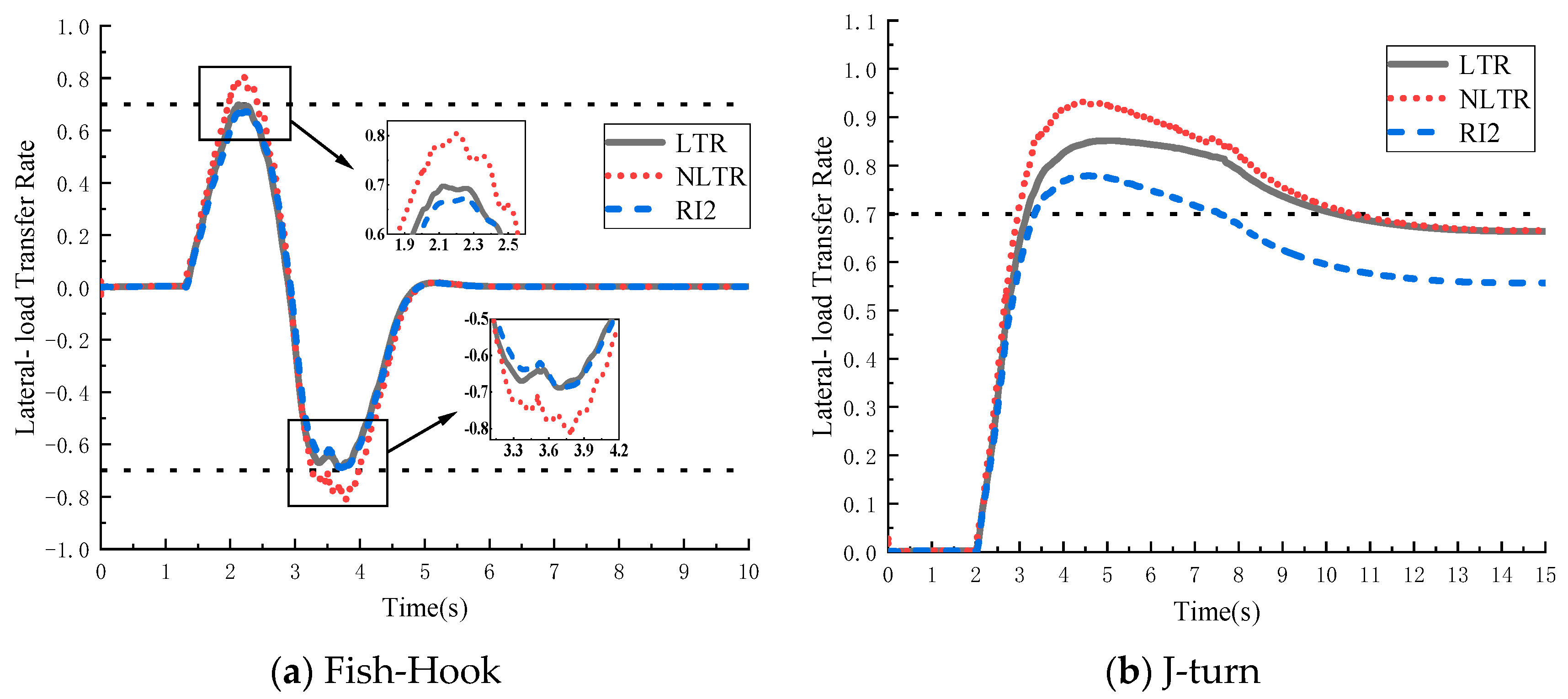
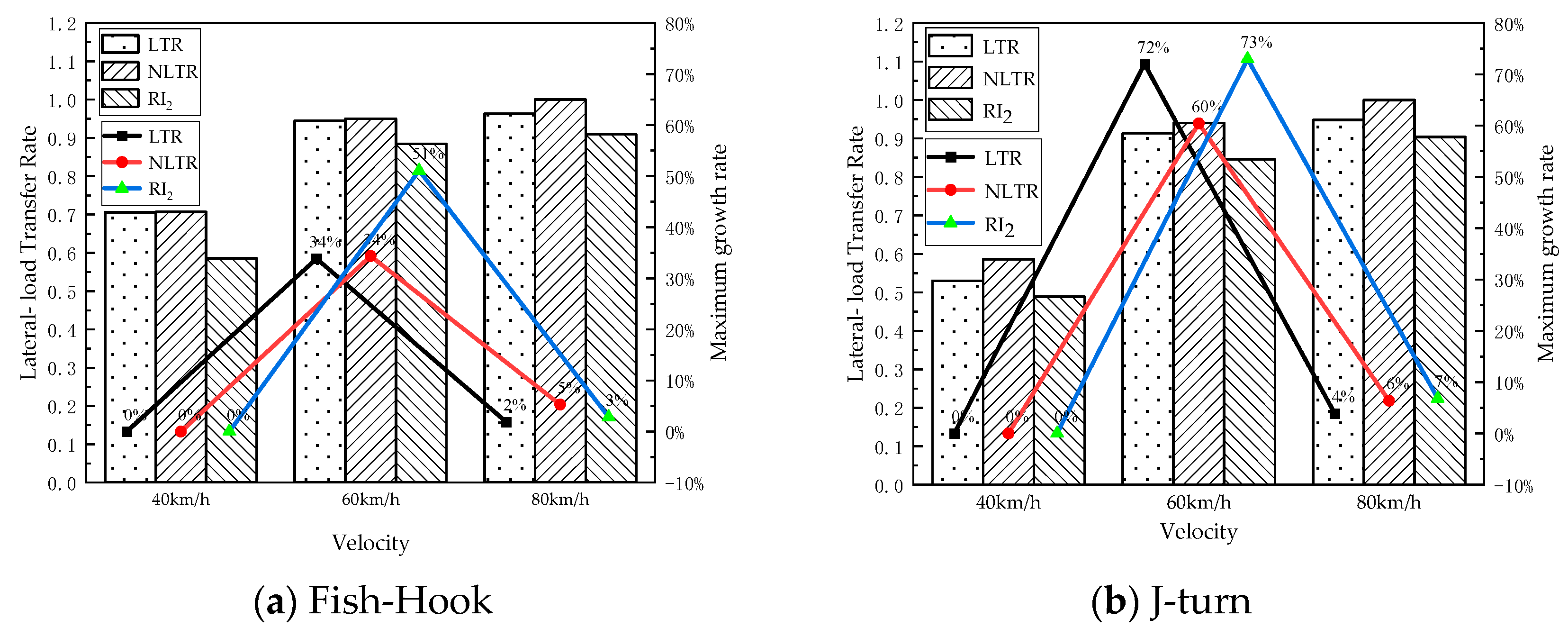
2.4. NLTR Index Validation

The fishhook and J-turn conditions, which can simulate the driver’s emergency steering during emergency obstacle avoidance, are the common rollover conditions used to study the lateral stability of vehicles [51]. Thus, the accuracy of the rollover indicator is verified under the fishhook and J-turn conditions, respectively. The rollover threshold determines the timing of triggering rollover control, and there is a slight difference in the speed of reaching the threshold value for different indicators, so the accuracy and merits of each indicator were analyzed when the vehicle is reaching the rollover queue. The results of the indicator validation are shown in Figure 3.
In Figure 3, the horizontal dashed line represents the vehicle rollover queue value. In order to further verify the applicability of NLTR indicators, the vehicle’s speed was set to 40, 60 or 80km/h, and the maximum values and trends of different indicators are compared. The results are shown in Figure 4.
In Figure 3 and Figure 4, it can be seen that when the vehicle has an ungrounded roll motion of the wheel due to the steering operation, the NLTR and the traditional LTR are basically consistent with the standard LTR trend. The maximum errors of NLTR and RI are about 9% and 7% compared with LTR. In Figure 4, the maximum growth rate refers to the percentage of the maximum value of the index increasing with the increase in speed from 40 to 80 km/h. As the speed increases, the change in the maximum value of the index shows a rule of fast first and then slow, indicating that both RI2 and NLTR can be used as vehicle-rollover indicators. At the same time, the lateral instability of the vehicle often occurs in an instant, and it is necessary to judge and control the rollover of the vehicle in a short time. NLTR has better sensitivity than RI2, while ensuring accuracy. When the vehicle has a risk of rollover, NLTR can quickly reach the rollover threshold and trigger the anti-rollover controller more quickly than RI2, so as to give full play to the effect of the controller. Therefore, the NLTR index can be selected as the trigger controller switch and provide the basis for further building an anti-rollover control strategy for heavy vehicles.
In summary, NLTR has superior accuracy compared with the standard LTR, and has superior sensitivity compared with RI2, so it can be used as a trigger controller switch.

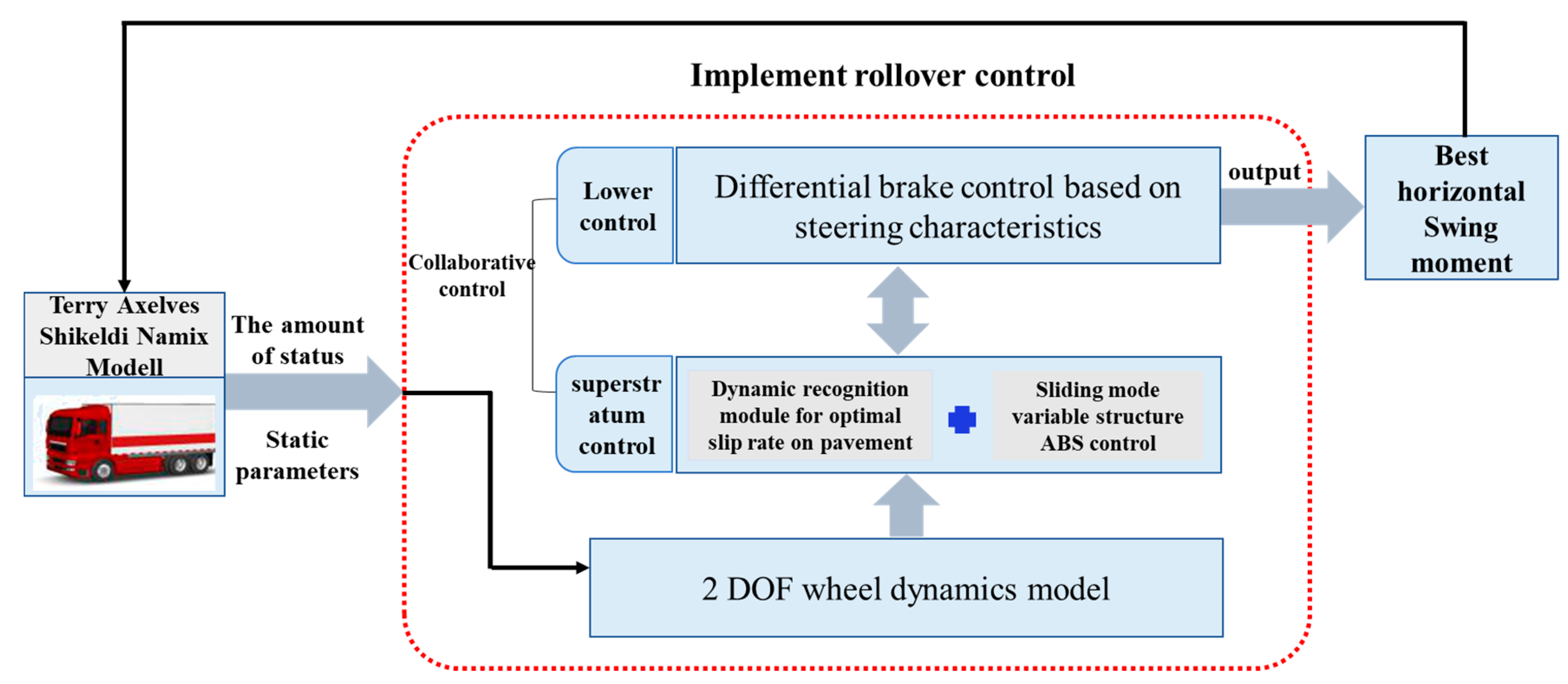
3. NLTR-Based Hierarchy Control Strategy for Anti-Rollover

In the hierarchical control framework, the complex suspension system, steering system and braking system in the vehicle chassis control system can be divided into upper control and lower control. In this section, the upper control mainly includes the optimal slip ratio (optimal adhesion coefficient) system, the controller based on sliding-mode variable structure ABS and the lower control with the steering-differential braking control. The lower layer control accepts the dynamic information from the upper-layer control and corrects the decision scheme of the upper-layer control with the NLTR. The anti-rollover control strategy logic based on the NLTR index is shown in Figure 5.

3.1. Anti-Rollover Upper-Level Controller

In the anti-rollover control strategy of electric heavy vehicles, the upper controller is composed of the optimal slip ratio identification system and the ABS braking system based on the sliding-mode variable-structure controller. In this paper, the controller is designed by simplifying all wheels to a 2-DOF model with a longitudinal axis and rotation. The equations of motion are shown in Equation (15).
{ M V ˙ x = F x F x R T b = I ω ˙ F x = μ M g ,
where v x is the longitudinal velocity, F x is the longitudinal friction, I is the wheel inertia, R is the wheel’s rolling radius, ω is the angular velocity of wheel rotation, T b is the braking torque and μ is the road-adhesion coefficient.

3.1.1. Optimal Slip Rate Identification

The relationship between pavement adhesion coefficient and slip rate can be expressed by Equation (16) [52].
μ ( s ) = c 1 ( 1 e c 2 s ) c 3 s ,
where s is the slip rate. c 1 , c 2 and c 3 are the corresponding fitting coefficients.
The values are shown in Table 1 [52].
The optimal slip rate and the maximum adhesion coefficient are shown by Equation (17).
{ s g = 1 c 2 log c 3 c 1 c 2 μ ( s g ) = c 1 c 3 c 2 ( 1 + log c 3 c 1 c 2 ) ,
where s g is the optimal slip rate and μ ( s g ) is the maximum adhesion coefficient.
The angular acceleration of wheel braking is shown by Equation (18)
d ω d t = d ( V ω / R ) d t ,
where V ω is the actual wheel speed. The algorithm for the identification of the optimal slip rate of the road surface can be found in a paper by our group [52].

3.1.2. Sliding-Mode Variable-Structure Controller

The anti-rollover control of heavy-duty vehicles is often discontinuous and instantaneous, which requires high accuracy and responsiveness of control algorithms. The system structure of sliding-mode variable-structure control can be continuously adjusted and optimized according to the current state of the system. As the sliding mode of the sliding-mode variable-structure controller can be set artificially and has nothing to do with the parameters of the control object, it has the advantage of strong adaptability [53,54]; at the same time, the sliding mode in a sliding-mode variable structure can be set artificially, which is independent of the control object and has the advantage of responding fast. Based on the characteristics of the above sliding-mode variable-structure control, the algorithm can be applied to the anti-rollover control of heavy vehicles.
The purpose of the sliding-mode variable controller is to make the error between the actual slip rate and the optimal slip rate tend to zero. Assuming that the optimal slip rate is known, the design of the sliding-mode surface is shown in Equation (19).
{ s ( t ) = λ ( t ) λ d ( t ) s ˙ = λ ˙ λ ˙ d = K sgn ( s ) 0 v = 1 2 s 2 v ˙ = s s ˙ = s K sgn ( s ) 0 ,
where λ is the actual slip ratio and λ d is the optimal slip ratio.
From Equations (15) and (19), the required braking torque of the wheel under sliding mode control is shown in Equation (20).
T b = M V ˙ R 2 I V [ 1 λ λ ˙ d + K s n g ( s ) ] R
The saturation function is used to shake the sliding-mode controller. The saturation function can reduce the chattering caused by the sliding-mode controller to some extent [55]. The saturation function s a t ( S Ω ) is approximately equal to sgn ( s ) , and in order to combine the saturation function with the sliding-mode control, sgn ( s ) can be replaced by s a t ( S Ω ) . The result is shown in Equation (21).
s a t ( S Ω ) = { 1 S Ω S Ω | S | < Ω 1 S Ω
where S is the sliding-mode function and Ω is the boundary thickness.
Bringing Equation (21) into Equation (20) yields the torque required during braking as Equation (22).
T b = M V ˙ R 2 I V [ 1 λ λ ˙ d + K s a t ( S Ω ) ] R

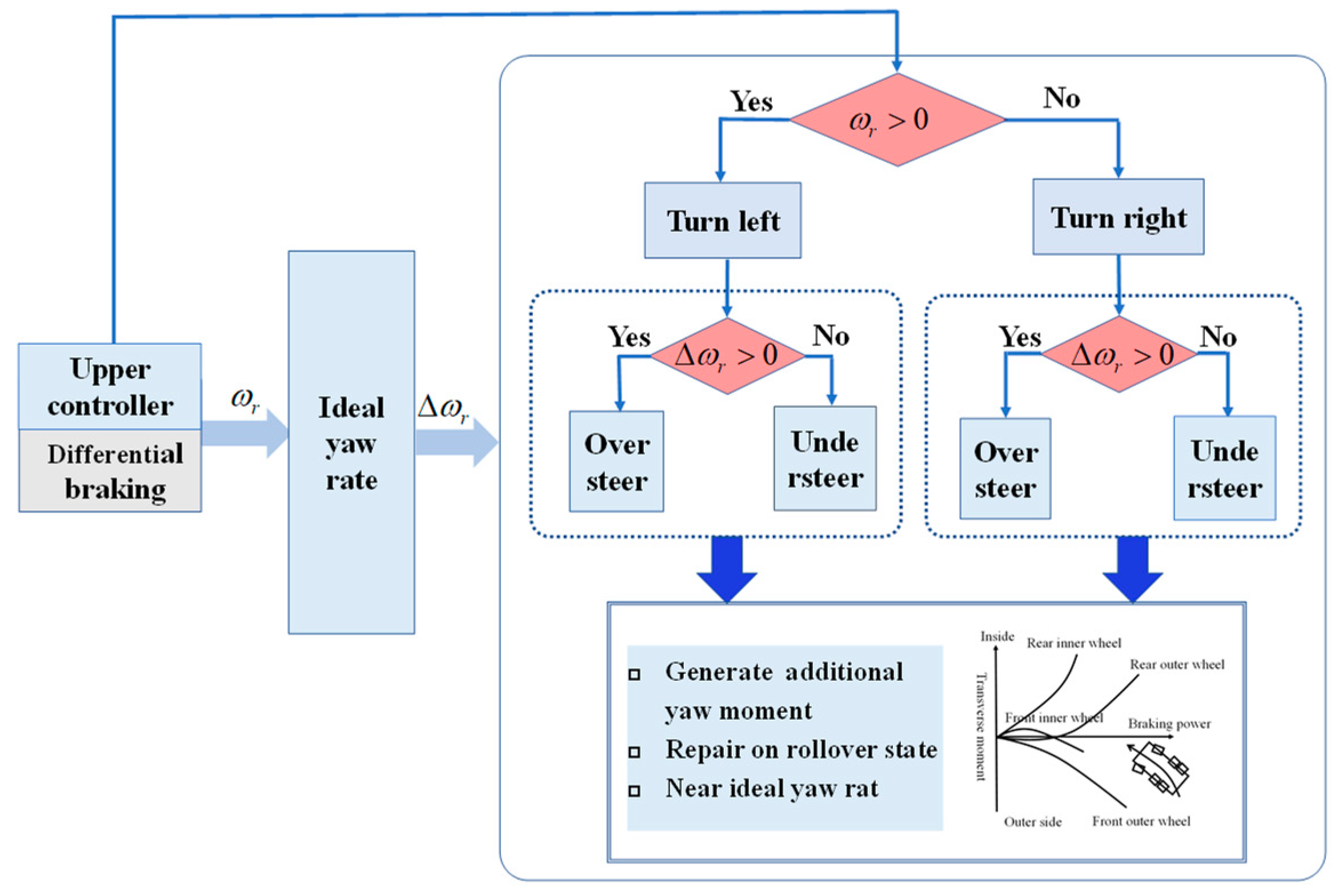
3.2. Anti-Rollover Lower-Level Controller

The upper control based on sliding mode variable structure and optimal slip rate identification were mentioned earlier, but the corresponding hardware must be implemented to truly put such a controller into actual vehicle control. The current distributed-wheel-drive vehicles provide convenient conditions for timely adjustment of the braking torque in each wheel. The lower controller designed in this section provides differential braking control. Differential braking control actually provides independent braking control for a single wheel or multiple wheels, but the overall control goal is to adjust the braking force of a wheel of the vehicle separately, so that the vehicle generates additional yaw moment, and uses the moment to correct its state, especially to make the transient instability of rollover close to the ideal yaw rate. The differential braking control logic is shown in Figure 6.
ω r is the actual yaw rate, Δ ω r is the difference between the actual yaw rate and ideal yaw rate.

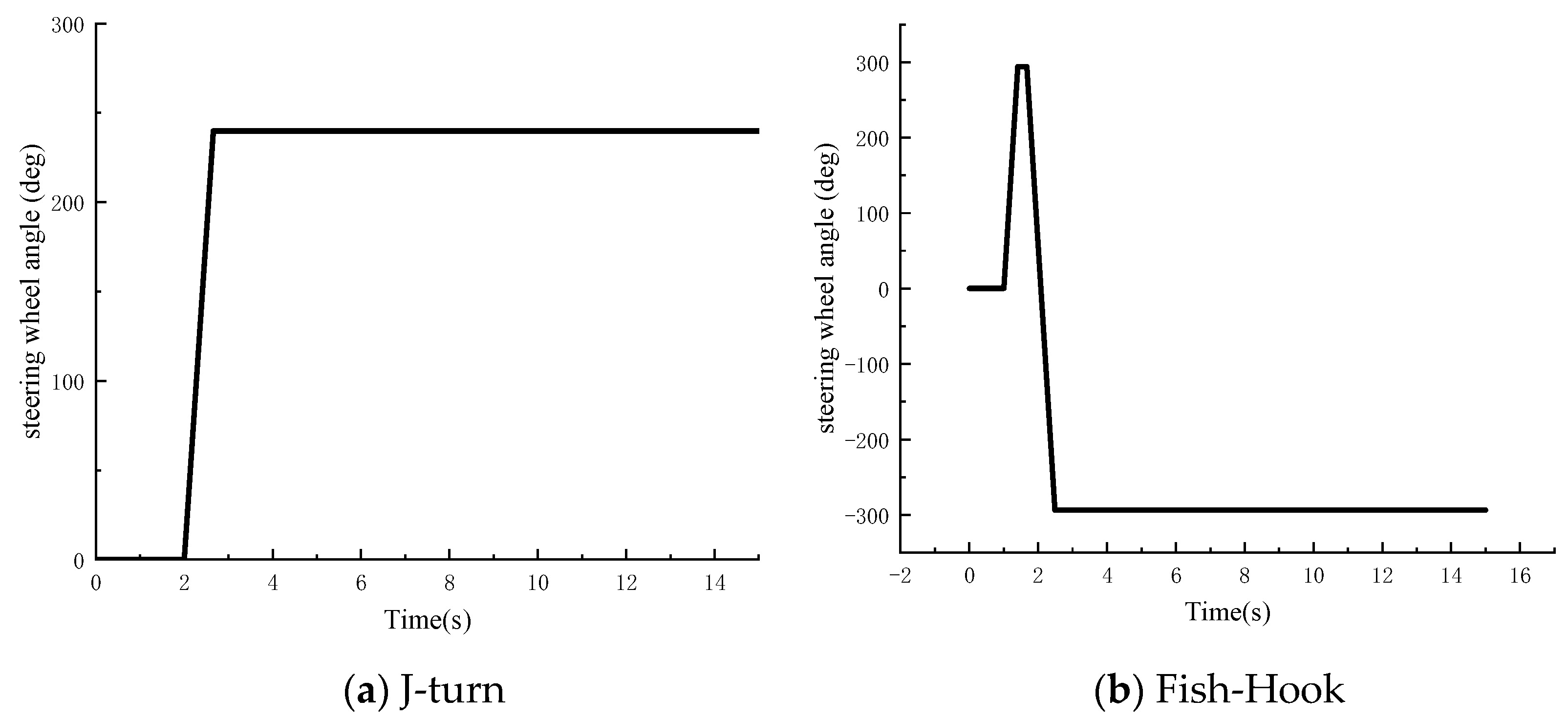
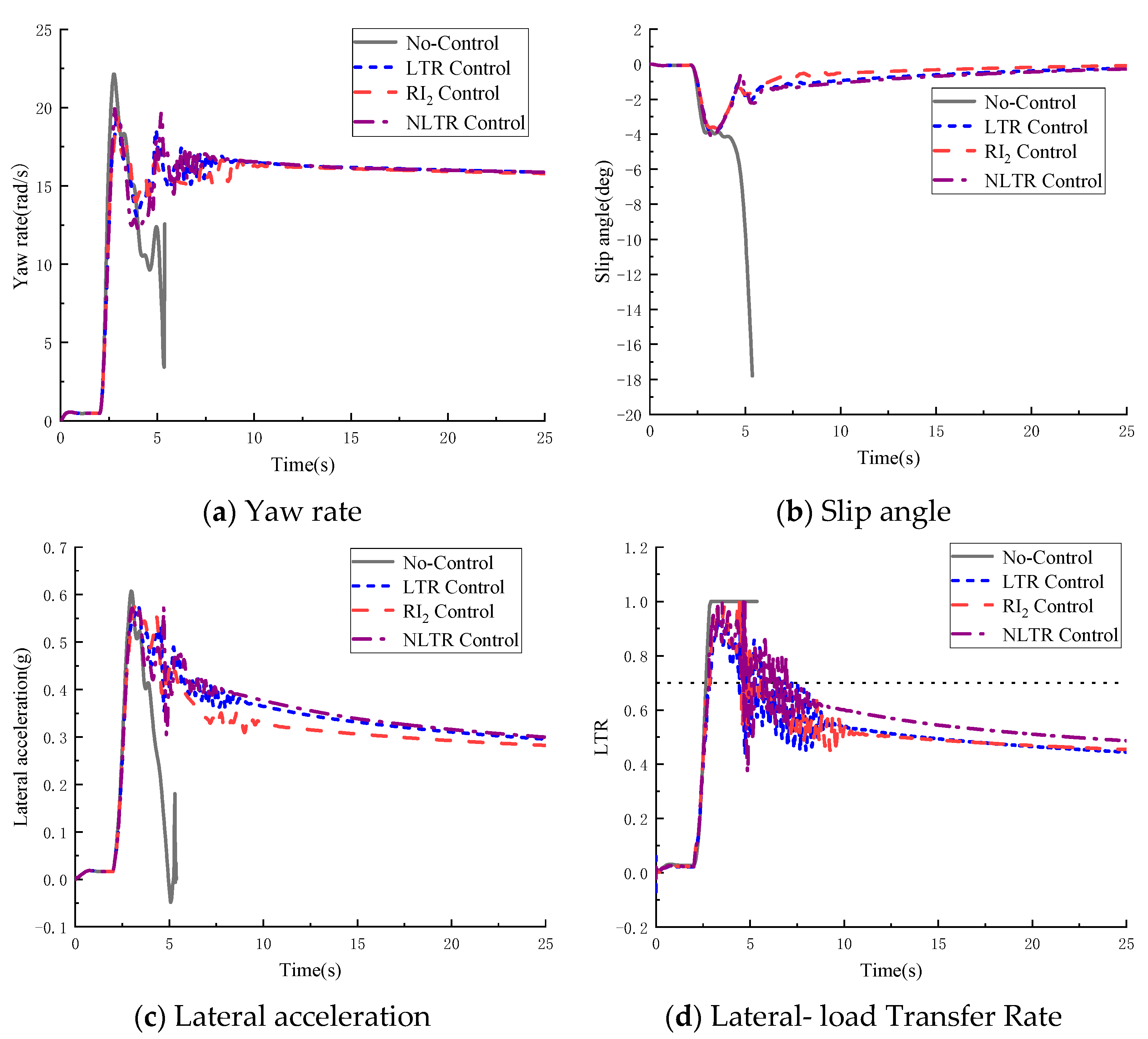
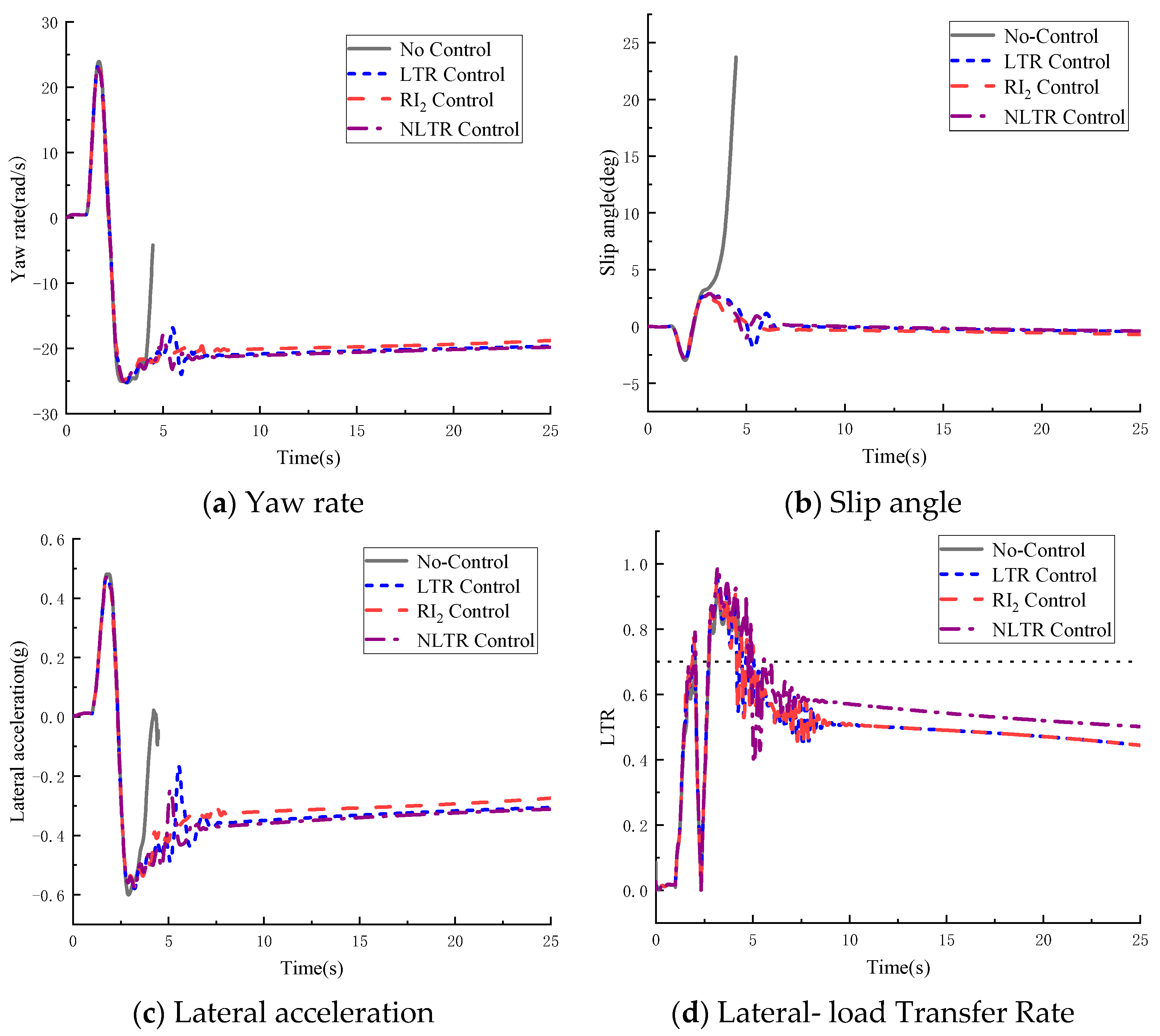
4. Heavy-Vehicle-Rollover Prevention Simulation Analysis

TruckSim software is commercial vehicle dynamics simulation software. The software is easy to operate and has high simulation accuracy. At the same time, it can be co-simulated with MATLAB/Simulink and has strong scalability [56]. In order to verify the effectiveness of the hierarchical control under the NLTR sideswipe factor determination condition, two different working conditions, J-turn and fishhook, were set up in TruckSim, and their main parameters are shown in Table 2, and the steering wheel angle inputs are shown in Figure 7. The results of comparing the transverse angular velocity, mass lateral deflection angle, lateral acceleration and lateral load transfer rate under the two working conditions are shown in Figure 8 and Figure 9.
It can be seen in Figure 8 and Figure 9 that under two different working conditions, the uncontrolled heavy vehicle experiences rollover. After applying intelligent hierarchical control, the rollover tendency of the vehicle body is effectively controlled, and the rollover is effectively prevented. When the NLTR is the control switch, the sideslip angle, yaw rate, lateral acceleration and lateral load transfer rate are effectively controlled in the steering process, and the change trend of each parameter is the same as that under the standard LTR control. Compared with RI2 control, under NLTR control, the changes in each parameter are more consistent with the changes in parameters under LTR control, and finally, the parameters were kept in safe ranges.

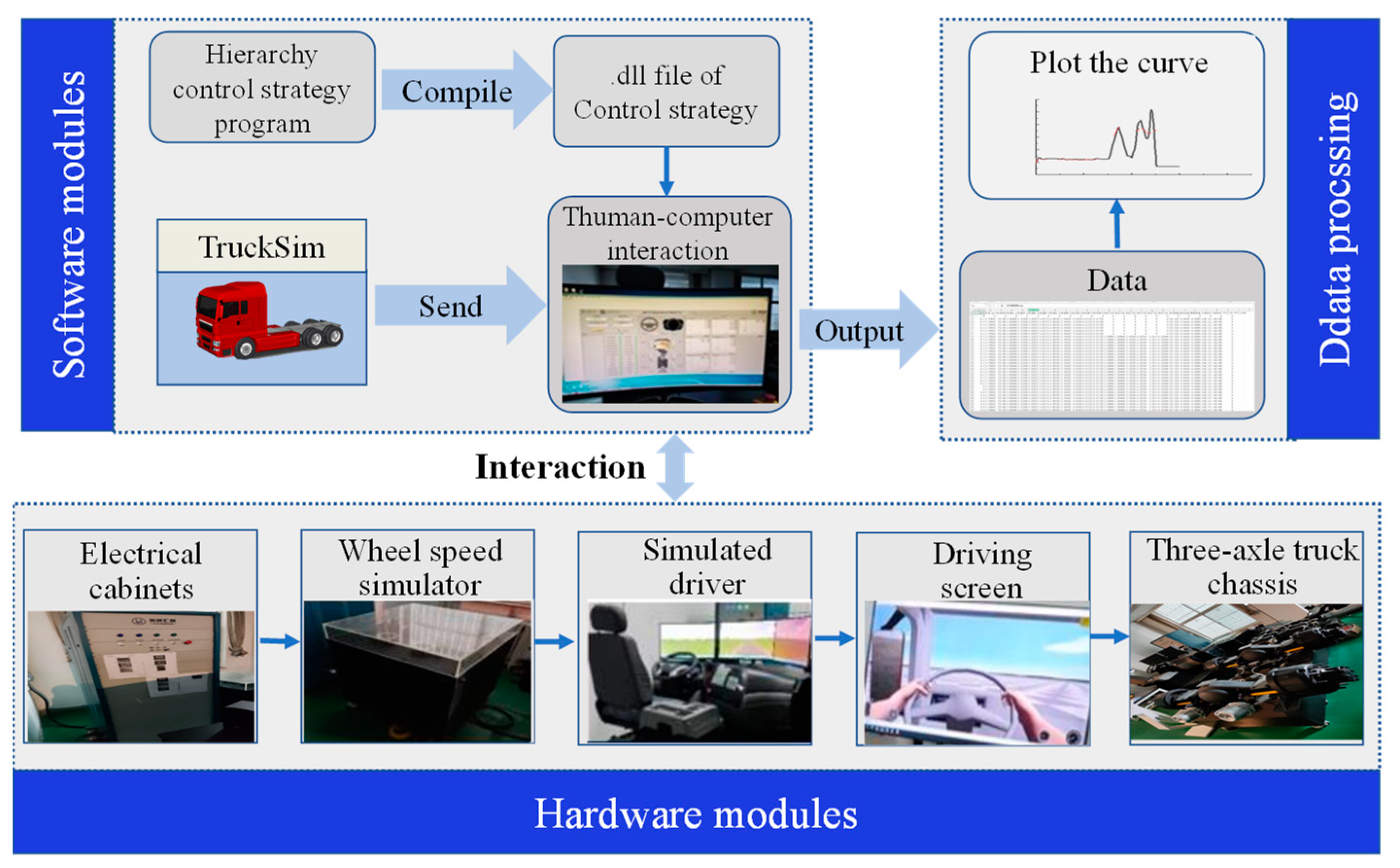
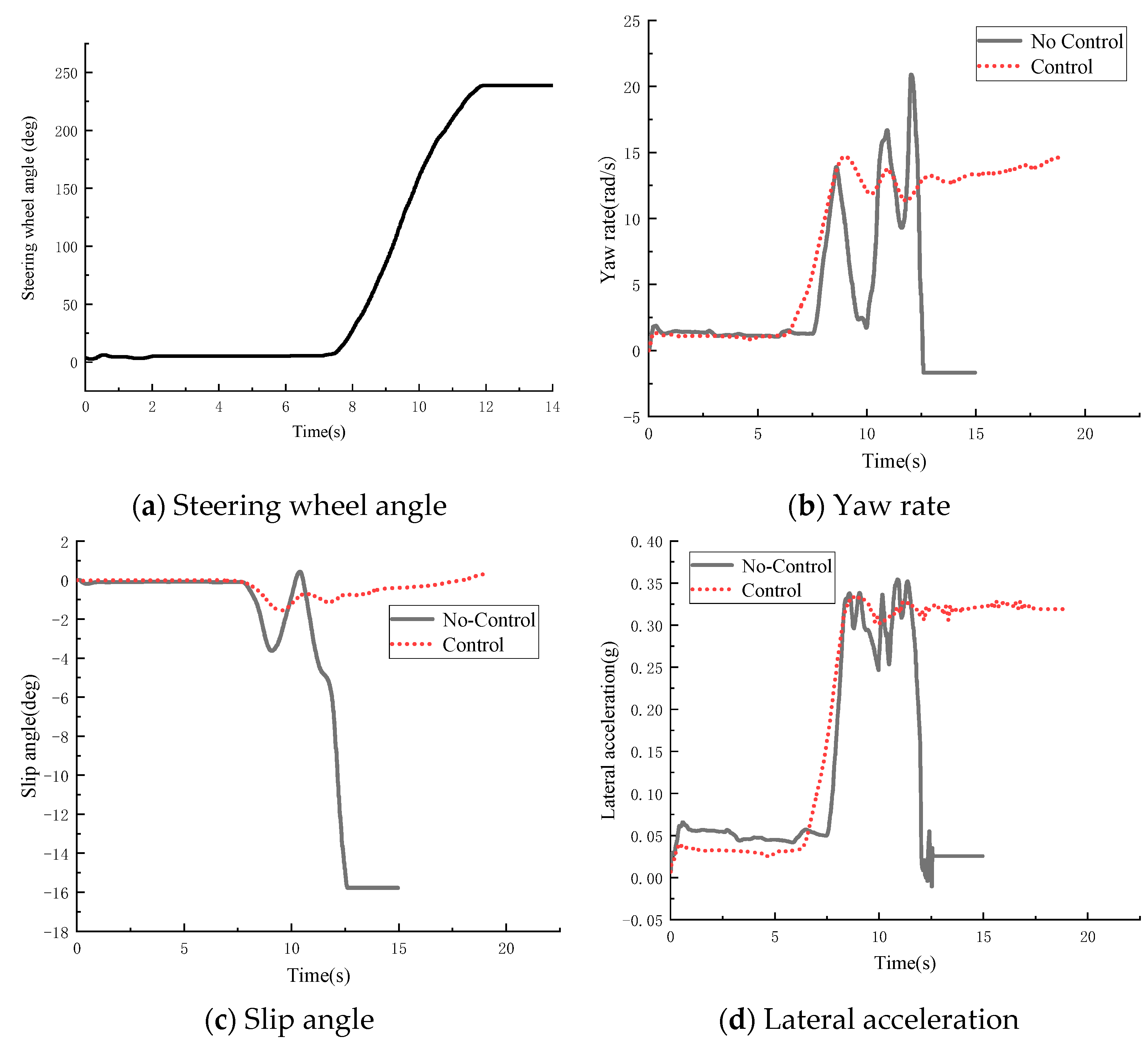
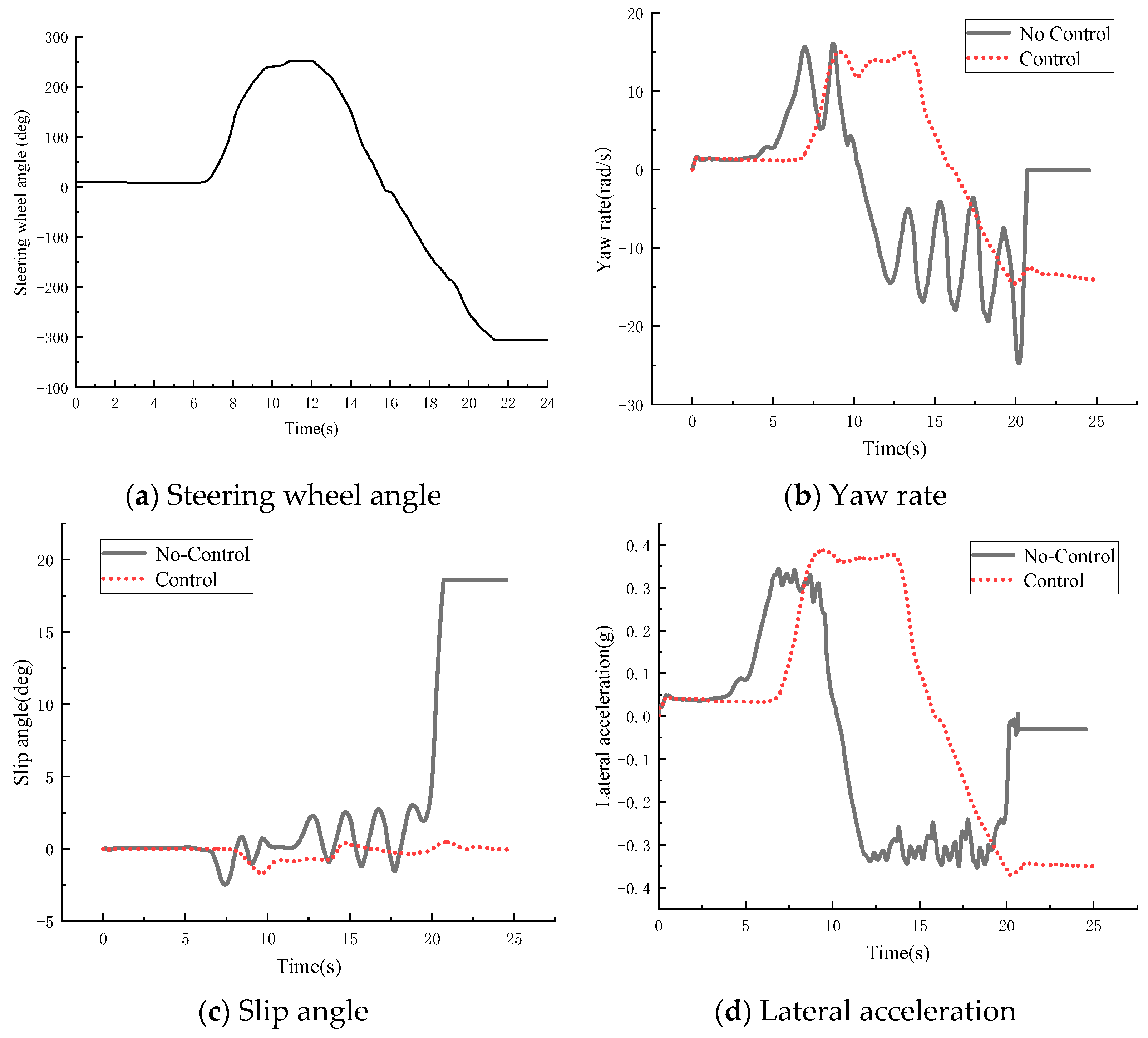
5. HIL Test Analysis

Since there is a certain danger in conducting a real vehicle-rollover test, the HIL test was used to simulate the driving of the vehicle under the extreme working condition, and the HIL test has superior accuracy compared with the simulation test. The HIL test bench co-simulates Trucksim with Labview and uses PXI as the platform. The core components can realize the HIL simulation of the steering system and braking system in the real vehicle. The HIL test is based on the Dongfeng commercial vehicle DFL1250A12 test bench. The experimental platform is divided into a driving simulator, braking platform, wheel speed simulator, electrical cabinet console and six parts of the stand. The operation flow of the three-axle heavy vehicle is shown in Figure 10.
To further verify the effectiveness of the built anti-rollover control algorithm and the feasibility for HIL control, a HIL test was conducted for a three-axis heavy vehicle. The test results under the angular step condition are shown in Figure 11.
It can be seen in Figure 11 that the vehicle started to turn after 6 s. When there was no control, its yaw rate rose rapidly to 14 rad/s and fluctuated between 2.5 and 16 rad/s. The sideslip angle fluctuated between −4 and 1 deg. At 11 s, the yaw rate and the sideslip angle increased sharply, and the lateral acceleration changed from 0.35 g to 0. When the hierarchical control is used, the value of each index increases instantaneously to a large value when the vehicle turns. At this time, the controller begins to work and controls the vehicle. Finally, the yaw rate, sideslip angle and lateral acceleration of the vehicle were stabilized at 12.72 rad/s, −0.54 deg, and 0.36 g, respectively. Compared with no control, the maximum yaw rate, slip angle and lateral acceleration were reduced by 9%, 16% and 3%, respectively, which successfully prevented the vehicle from rolling over.
The results of the HIL test for the fishhook condition are shown in Figure 12.
From Figure 12, it is known that under the fishhook condition, when the vehicle is not controlled, due to the correction effect of the second steering on the first steering, the vehicle will not roll during the first steering, but the yaw rate will fluctuate between 5 and 15 rad/s in 6~9 s; when the vehicle turns for the second time and runs for 20 s, the yaw rate and lateral acceleration will suddenly change to 0 after severe jitter, and the sideslip angle of the center of mass will rise sharply to 18.5 deg, and the vehicle will roll over. Compared with no control, the yaw rate did not fluctuate greatly during the first steering under the hierarchical control. At the 20th second, the control condition triggered and stabilized the yaw rate, sideslip angle and lateral acceleration at 12.5 rad/s, 0.25 deg and 0.35 g. Compared with no control, the maximum yaw rate, slip angle and lateral acceleration are reduced by 12%, 18% and 3%, respectively, eliminating the danger of vehicle rollover.

6. Conclusions

A spatial dynamics model of the whole heavy vehicle was established, and a new rollover evaluation index was proposed based on LTR. The NLTR index proposed in this paper solves the problem of directly measuring and estimating tire force and expresses the change in load indirectly with measurable parameters. The improved rollover evaluation index was verified under the angular step and fishhook conditions. For the characteristics of independently adjustable wheels of heavy-duty vehicles, a hierarchy controller based on the identification of the best slip rate of the road surface, ABS control with sliding-mode variable structure and differential braking under the new rollover evaluation index as the controller switching condition was designed. Simulation and HIL tests proved that the designed controller can significantly improve the lateral stability of the vehicle under extreme operating conditions. Under the J-turn condition, the proposed hierarchical control strategy reduced the maximum yaw rate, slip angle and lateral acceleration by 9%, 16% and 3% respectively. Under the condition of fishhooking, the maximum yaw rate, sideslip angle and lateral acceleration were reduced by 12%, 18% and 3% respectively.
In the next step, the longitudinal lateral–vertical coupling model of a heavy-duty vehicle will be studied to further improve the accuracy of the estimation algorithm. A more sophisticated index will be investigated which can predict both untripped and tripped rollover. Additionally, the multi-objective cooperative control will be studied to maintain the trajectories of the controlled vehicles.

Author Contributions

Conceptualization, Y.L.; formal analysis, Y.L.; funding acquisition, Y.L.; investigation, L.Z., H.L., and J.Z.; methodology, L.Z. and Y.L.; resources, Y.L.; software, L.Z.; supervision, Y.L.; validation, L.Z., Y.L., and J.Z.; writing—original draft, L.Z.; writing—review and editing, L.Z., Y.L., and H.L. All authors have read and agreed to the published version of the manuscript.

Funding

This work was supported by the National Natural Science Foundation of China under grant number 12072204; National Natural Science Foundation of China under grant number 11572207; Natural Science Foundation of Hebei Province under grant number A2020210039.

Institutional Review Board Statement

Not applicable.

Informed Consent Statement

Not applicable.

Data Availability Statement

Not applicable.

Conflicts of Interest

The authors declare no conflict of interest.

References

  1. National Highway Traffic Safety Administration. Traffic Safety Facts 2016: A Compilation of Motor Vehicle Crash Date from the Fatality Analysis Reporting System and the General Estimates System; US Department of Transportation: Washington, DC, USA, 2018; pp. 70–77.
  2. Abu-Zidan, F.M.; Eid, H.O. Factors affecting injury severity of vehicle occupants following road traffic collisions. Injury 2015, 46, 136–141. [Google Scholar] [CrossRef] [PubMed]
  3. Kordani, A.A.; Molan, A.M. The effect of combined horizontal curve and longitudinal grade on side friction factors. KSCE J. Civ. Eng. 2015, 19, 303–310. [Google Scholar] [CrossRef]
  4. Doumiati, M.; Sename, O.; Dugard, L.; Martinez-Molina, J.-J.; Gaspar, P.; Szabo, Z. Integrated vehicle dynamics control via coordination of active front steering and rear braking. Eur. J. Control. 2013, 19, 121–143. [Google Scholar] [CrossRef] [Green Version]
  5. Ye, Z.; Xie, W.; Yin, Y.; Fu, Z. Dynamic Rollover Prediction of Heavy Vehicles Considering Critical Frequency. Automot. Innov. 2020, 3, 158–168. [Google Scholar] [CrossRef]
  6. Huang, G.; Yuan, X.; Shi, K.; Wu, X. A BP-PID controller-based multi-model control system for lateral stability of distributed drive electric vehicle. J. Frankl. Inst. 2019, 356, 7290–7311. [Google Scholar] [CrossRef]
  7. Jin, Z.L.; Chen, G.Y.; Zhao, W.Z. Rollover stability analysis and control of in-wheel motor drive electric vehicles. China Mech. Eng. 2018, 29, 1772–1779. [Google Scholar]
  8. Shi, K.; Yuan, X.; Liu, L. Model predictive controller-based multi-model control system for longitudinal stability of distributed drive electric vehicle. ISA Trans. 2018, 72, 44–55. [Google Scholar] [CrossRef]
  9. Zhang, L.P.; Duan, J.Y.; Su, T.; Ren, C.H. Cooperative control of spatial stability chassis for electric wheel drive vehicles. J. Mech. Eng. 2022, 58, 209–221. [Google Scholar]
  10. Saglam, F.; Unlusoy, Y.S. Adaptive ride comfort and attitude control of vehicles equipped with active hydro-pneumatic suspension. Int. J. Veh. Des. 2016, 71, 31. [Google Scholar] [CrossRef]
  11. Jin, Z.; Li, J.; Huang, Y.; Khajepour, A. Study on Rollover Index and Stability for a Triaxle Bus. Chin. J. Mech. Eng. 2019, 32, 64. [Google Scholar] [CrossRef] [Green Version]
  12. Chen, S.; Zhang, H.D.; Wu, H.D.; Zhang, F.J.; Jiang, X.Y. Research on vehicle anti-rollover based on combined control of active lateral stabilizer bar and differential braking. Automot. Eng. 2019, 41, 1043–1049. [Google Scholar]
  13. Pourasad, Y.; Mahmoodi-k, M.; Oveisi, M. Design of an optimal active stabilizer mechanism for enhancing vehicle rolling resistance. J. Central South Univ. 2016, 23, 1142–1151. [Google Scholar] [CrossRef]
  14. Yakub, F.; Lee, S.; Mori, Y. Comparative study of MPC and LQC with disturbance rejection control for heavy vehicle rollover prevention in an inclement environment. Mech. Sci. Technol. 2016, 30, 3835–3845. [Google Scholar] [CrossRef]
  15. Liu, C.W.; Xu, T.S.; Li, T.; Zhang, J.H.; Lin, J.W.; Jia, H.J.; Li, Y.H.; Wang, J.C. Ride comfort simulation and optimization of heavy-duty trucks based on human-vehicle coupling dynamics model. J. Tianjin Univ. (Nat. Sci. Eng. Technol. Ed.) 2020, 53, 736–744. [Google Scholar]
  16. Wang, Y.; Yuan, L.; Chen, H.; Du, P.; Lian, X. An anti-slip control strategy with modifying target and torque reallocation for heavy in-wheel motor vehicle. Proc. Inst. Mech. Eng. Part D J. Automob. Eng. 2022, 236, 2625–2644. [Google Scholar] [CrossRef]
  17. Tota, A.; Dimauro, L.; Velardocchia, F.; Paciullo, G.; Velardocchia, M. An Intelligent Predictive Algorithm for the Anti-Rollover Prevention of Heavy Vehicles for Off-Road Applications. Machines 2022, 10, 835. [Google Scholar] [CrossRef]
  18. Liu, J. Optimal Design and Analysis of Intelligent Vehicle Suspension System Based on ADAMS and Artificial Intelligence Algorithms. J. Physics: Conf. Ser. 2021, 2074, 012023. [Google Scholar] [CrossRef]
  19. Sivaramakrishnan, P.; Prakash, A.K.M.; Sekulic, D.; Jacobson, B.; Selvi, C.; Johannesen, S.M. Methods to introduce floating bridge motion and wind excitation on a model for the investigation of heavy vehicle dynamics. Appl. Math. Model. 2023, 117, 118–141. [Google Scholar] [CrossRef]
  20. Deng, Z.W.; Zhao, Y.Q.; Wang, B.H.; Gao, W.; Kong, X. A preview driver model based on sliding-mode and fuzzy control for articulated heavy vehicle. Meccanica 2022, 57, 1853–1878. [Google Scholar] [CrossRef]
  21. Arslan, M.S.; Sever, M. Vehicle stability enhancement and rollover prevention by a nonlinear predictive control method. Trans. Inst. Meas. Control. 2019, 41, 2135–2149. [Google Scholar] [CrossRef]
  22. Saeedi, M.A.; Kazemi, R.; Azadi, S. Improvement in the rollover stability of a liquid-carrying articulated vehicle via a new robust controller. Proc. Inst. Mech. Eng. Part D J. Automob. Eng. 2017, 231, 322–346. [Google Scholar] [CrossRef]
  23. Jin, X.; Wang, J.; He, H.; Yan, Z.; Xu, L.; Wei, C.; Yin, G. Improving Vibration Performance of Electric Vehicles Based on In-Wheel Motor-Active Suspension System via Robust Finite Frequency Control. IEEE Trans. Intell. Transp. Syst. 2022. [Google Scholar] [CrossRef]
  24. Odenthal, D.; Bünte, T.; Ackermann, J. Nonlinear steering and braking control for vehicle rollover avoidance. In Proceedings of the 1999 European Control Conference (ECC), Karlsruhe, Germany, 31 August–3 September 1999; pp. 598–603. [Google Scholar]
  25. Phanomchoeng, G.; Rajamani, R. New rollover index for the detection of tripped and untripped rollovers. IEEE Trans. Ind. Electron. 2012, 60, 4726–4736. [Google Scholar] [CrossRef]
  26. Dahmani, H.; Chadli, M.; Rabhi, A.; El Hajjaji, A. Detection of impending vehicle rollover with road bank angle consideration using a robust fuzzy observer. Int. J. Autom. Comput. 2015, 12, 93–101. [Google Scholar] [CrossRef]
  27. Jin, Z.; Zhang, L.; Zhang, J.; Khajepour, A. Stability and optimised H∞ control of tripped and untripped vehicle rollover. Veh. Syst. Dyn. 2016, 54, 1405–1427. [Google Scholar] [CrossRef]
  28. Jin, Z.; Li, J.; Huang, S. Rollover detection and prevention of a heavy-duty vehicle on banked and graded uneven road. Int. J. Veh. Des. 2021, 87, 218–248. [Google Scholar] [CrossRef]
  29. Ataei, M.; Khajepour, A.; Jeon, S. Model predictive rollover prevention for steer-by-wire vehicles with a new rollover index. Int. J. Control. 2020, 93, 140–155. [Google Scholar] [CrossRef]
  30. Zhao, W.; Ji, L.; Wang, C. H∞ control of integrated rollover prevention system based on improved lateral load transfer rate. Trans. Inst. Meas. Control. 2019, 41, 859–874. [Google Scholar] [CrossRef]
  31. Shin, D.; Woo, S.; Park, M. Rollover Index for Rollover Mitigation Function of Intelligent Commercial Vehicle’s Electronic Stability Control. Electronics 2021, 10, 2605. [Google Scholar] [CrossRef]
  32. Vempaty, S.; He, Y.; Zhao, L. An overview of control schemes for improving the lateral stability of car-trailer combinations. Int. J. Veh. Perform. 2020, 6, 151–199. [Google Scholar] [CrossRef]
  33. Liu, W.; He, H.; Sun, F.; Lv, J. Integrated chassis control for a three-axle electric bus with distributed driving motors and active rear steering system. Veh. Syst. Dyn. 2017, 55, 601–625. [Google Scholar] [CrossRef]
  34. Soltani, A.; Bagheri, A.; Azadi, S. Integrated vehicle dynamics control using semi-active suspension and active braking systems. Proc. Inst. Mech. Eng. Part K J. Multi Body Dyn. 2018, 232, 314–329. [Google Scholar] [CrossRef]
  35. Dong, E.; Zhang, L.; Zhang, K.; Qin, C. Research for vehicle anti-rollover control based on differential braking. In Proceedings of the 2019 International Conference on Computer Network, Electronic and Automation (ICCNEA), Xi’an, China, 27–29 September 2019; pp. 486–490. [Google Scholar]
  36. Termous, H.; Shraïm, H.; Talj, R.; Francis, C.; Charara, A. Coordinated control strategies for active steering, differential braking and active suspension for vehicle stability, handling and safety improvement. Veh. Syst. Dyn. 2019, 57, 1494–1529. [Google Scholar] [CrossRef]
  37. Chang, X.; Zhang, H.; Yan, S.; Hu, S.; Meng, Y. Analysis and roll prevention control for distributed drive electric vehicles. World Electr. Veh. J. 2022, 13, 210. [Google Scholar] [CrossRef]
  38. Zang, L.; Wu, Y.; Wang, X.; Wang, Z.; Li, Y. Stability control of a vehicle with tire blowout based on active steering and differential braking. Int. J. Model. Simul. Sci. Comput. 2022, 13, 2250032. [Google Scholar] [CrossRef]
  39. Wang, G.; Liu, L.; Meng, Y.; Gu, Q.; Bai, G. Integrated Path Tracking Control of Steering and Differential Braking Based on Tire Force Distribution. Int. J. Control. Autom. Syst. 2022, 20, 536–550. [Google Scholar] [CrossRef]
  40. Lu, Y.; Han, Y.; Huang, W.; Wang, Y. Sliding mode control for overturning prevention and hardware-in-loop experiment of heavy-duty vehicles based on dynamical load transfer ratio prediction. Proc. Inst. Mech. Eng. Part K J. Multi Body Dyn. 2022, 236, 68–83. [Google Scholar] [CrossRef]
  41. Jin, X.; Wang, J.; Yan, Z.; Xu, L.; Yin, G.; Chen, N. Robust Vibration Control for Active Suspension System of In-Wheel-Motor-Driven Electric Vehicle Via μ-Synthesis Methodology. ASME Trans. J. Dyn. Syst. Meas. 2022, 144, 051007. [Google Scholar] [CrossRef]
  42. He, L.; Pan, Y.; He, Y.; Li, Z.; Królczyk, G.; Du, H. Control strategy for vibration suppression of a vehicle multibody system on a bumpy road. Mech. Mach. Theory 2022, 174, 104891. [Google Scholar] [CrossRef]
  43. Silva, F.L.; Silva, L.C.; Eckert, J.J.; Lourenço, M.A. Robust fuzzy stability control optimization by multi-objective for modular vehicle. Mech. Mach. Theory 2022, 167, 104554. [Google Scholar] [CrossRef]
  44. Chu, D.; Li, H.; Zhao, C.; Zhou, T. Trajectory Tracking of Autonomous Vehicle Based on Model Predictive Control With PID Feedback. IEEE Trans. Intell. Transp. Syst. 2022, 1–12. [Google Scholar] [CrossRef]
  45. Li, D.F.; Qin, F.; Wang, W.W.; Xu, H.; Liu, J.Q. Design and verification of hardware-in-the-loop virtual test system for unmanned vehicle. J. Chang‘an Univ. (Nat. Sci. Ed.) 2021, 41, 116–126. [Google Scholar]
  46. Guo, Y.S.; Zhang, H.J.; Fu, R.; Wang, C. Research on lateral control model of intelligent vehicle based on neuro-ergonomics. Automot. Eng. 2021, 43, 1057–1065. [Google Scholar]
  47. Ma, Y.Z.; Yan, T.Y.; Zhao, Y.L. Research on integrated control strategy of new electronically controlled air suspension system. Automot. Eng. 2021, 43, 1394–1401. [Google Scholar]
  48. Xu, N.; Li, X.Y. Handling stability control of four-wheel drive electric vehicle under combined conditions. J. Mech. Eng. 2021, 57, 205–220. [Google Scholar]
  49. Pacejka, H.B. Tyre and Vehicle Dynamics; Elsevier: Amsterdam, The Netherlands, 2005. [Google Scholar]
  50. Zhang, H.X. Study on Vertical-Lateral Coupling Dynamic Model and Control of Heavy-Duty Vehicles; Shijiazhuang University of Railways: Shijiazhuang, China, 2019. [Google Scholar]
  51. Mehrtash, M.; Yuen, T.; Balan, L. Implementation of experiential learning for vehicle dynamic in automotive engineering: Roll-over and fishhook test. Procedia Manuf. 2019, 32, 768–774. [Google Scholar] [CrossRef]
  52. Huang, W.H. Research on Anti-Rollover Sliding Mode Control of Heavy Vehicles Based on Kalman Filter Warning; Shijiazhuang Railway University: Shijiazhuang, China, 2020. [Google Scholar] [CrossRef]
  53. Gu, B.; Cong, J.; Zhao, J.; Chen, H.; Fatemi Golshan, M. A novel robust finite time control approach for a nonlinear disturbed quarter-vehicle suspension system with time delay actuation. Automatika 2022, 63, 627–639. [Google Scholar] [CrossRef]
  54. Sun, X.-Q.; Cai, Y.-F.; Yuan, C.-C.; Wang, S.-H.; Chen, L. Fuzzy Sliding Mode Control for the Vehicle Height and Leveling Adjustment System of an Electronic Air Suspension. Chin. J. Mech. Eng. 2018, 31, 25. [Google Scholar] [CrossRef] [Green Version]
  55. Hou, Y.; Wang, H.; Wei, Y.; Iu, H.H.-C.; Fernando, T. Robust adaptive finite-time tracking control for Intervention-AUV with input saturation and output constraints using high-order control barrier function. Ocean. Eng. 2023, 268, 113219. [Google Scholar] [CrossRef]
  56. Li, L.; Guo, T.; Xu, S. Simulation Analysis of Vehicle Handling Stability Based on Trucksim. J. Phys. Conf. Ser. IOP Publ. 2021, 1885, 032043. [Google Scholar] [CrossRef]
Figure 1. Vehicle model diagram.
Machines 11 00117 g001
Figure 2. Algorithmic flow of the new rollover evaluation index.
Machines 11 00117 g002
Figure 3. Comparison of three types of rollover indicators in time domain.
Machines 11 00117 g003
Figure 4. Comparison of three types of rollover indicators.
Machines 11 00117 g004
Figure 5. Anti-rollover control strategy based on the NLTR index.
Machines 11 00117 g005
Figure 6. Differential braking control logic diagram.
Machines 11 00117 g006
Figure 7. Steering wheel angle.
Machines 11 00117 g007
Figure 8. J-turn.
Figure 8. J-turn.
Machines 11 00117 g008
Figure 9. Fishhook.
Figure 9. Fishhook.
Machines 11 00117 g009
Figure 10. HIL flowchart.
Machines 11 00117 g010
Figure 11. J-turn.
Figure 11. J-turn.
Machines 11 00117 g011
Figure 12. Fishhook.
Machines 11 00117 g012
Table 1. Simulation parameters.
Pavement Type c 1 c 2 c 3
Dry Asphalt1.2823.990.52
Wet asphalt0.87533.8220.374
Cement1.19725.170.54
Dry cobblestone1.376.460.669
Wet pebbles0.4133.710.12
Ice0.05306.390.001
Snow0.19594.130.065
Table 2. Simulation parameters.
SymbolValueUnit
m z 20,000kg
m b 17,860kg
l 1 2m
l 2 1.5m
l 3 2.7m
h 1.173m
I x 2284.9Kg·m2
I y 35,408Kg·m2
I z 34,823Kg·m2
I x z 1626Kg·m2
B 1.863m
b 1 , b 2 0.9315m
k 1 , 2 250,000N/m
k 3 , 4 , 5 , 6 700,000N/m
c 1 , 2 15,000N/m/s
c 3 , 4 , 5 , 6 30,000N/m/s
m t 1 , m t 2 285kg
m t 3 , m t 4 , m t 5 , m t 6 392.5kg
Disclaimer/Publisher’s Note: The statements, opinions and data contained in all publications are solely those of the individual author(s) and contributor(s) and not of MDPI and/or the editor(s). MDPI and/or the editor(s) disclaim responsibility for any injury to people or property resulting from any ideas, methods, instructions or products referred to in the content.

