Article

Study on the Temperature Rise Characteristics of Successive Clutch Shifting Considering the Disengaged Friction Pair Gaps

School of Mechanical Engineering, Beijing Institute of Technology, Beijing 100081, China
*
Author to whom correspondence should be addressed.
Machines 2022, 10(7), 576; https://doi.org/10.3390/machines10070576
Submission received: 23 June 2022 / Revised: 13 July 2022 / Accepted: 15 July 2022 / Published: 17 July 2022
(This article belongs to the Special Issue Chassis Coordinated Control of Vehicles)

Abstract

:
The clutch temperature rise characteristics in successive shifting conditions are crucial to its thermal stability and thermal safety. In the present paper, a comprehensive numerical model is proposed to investigate the temperature change of separator discs during successive shifting with the consideration of convection heat transfer in disengaged friction pair gaps, which is validated by repeated shifting experiments on the SAE#2 test bench. Since the second separator disc near the piston has the widest disengaged gaps and double-sided heat input, its temperature rise and temperature drop are the highest. The temperature rise gradually equals the temperature drop with the increasing working cycle, then the maximum clutch temperature no longer increases. The longer the shifting interval, the better the heat dissipation is, thus the lower the accumulated temperature rise. Moreover, the increasing lubrication oil temperature reduces the convection heat transfer and increases the temperature rise in an engaging process, but the accumulated temperature rise does not increase due to the widened friction pair gaps. This paper can obtain the temperature rise characteristics of a wet multi-disc clutch concerning its disengaged gaps during successive shifting, which is a promising candidate for investigating its overall performance.

Graphical Abstract

1. Introduction

Determining the power transfer efficiency and gear shifting quality directly, the wet multi-disc clutch is widely used in vehicle automatic transmissions, the typical structure of which is shown in Figure 1. To improve the torque transfer capability and thermal stability of the wet clutch, considerable research efforts have been devoted to the mechanism of the friction torque [1] and the distribution of the temperature field [2].
The generation and variation mechanisms of the friction torque have been intensively investigated. Yu et al. [3,4] proposed a multi-field coupling numerical model to study the contact and lubrication mechanisms of friction pairs, and the influence of the operating parameters on the friction torque was revealed. Bao et al. [1] investigated the influence of the friction pair number and applied pressure on the friction torque through a kinematic coupling model. Li et al. [5] studied the influence of surface parameters on the friction performance of a carbon fabric wet clutch. Wang et al. [6] compared the clutch engaging characteristics influenced by the groove shape and groove depth. Further, Wang et al. [7] designed a new conical groove and researched its friction performance experimentally. The influence of radial and waffle grooves on the friction stability of a paper-based wet clutch was experimentally compared [8].
Due to the specific working mode of the wet clutch, large amounts of friction heat are inevitably generated during the short engaging process, thus causing a considerable and uneven temperature rise. A two-dimensional thermal model was proposed by Li et al. [9] to obtain the temperature field of a carbon fabric wet clutch and the influence law of thermal parameters on the clutch temperature rise. Additionally, Ma et al. [10] and Wu et al. [11] studied the clutch temperature rise characteristics under the long-time sliding condition. Yang et al. [12] and Yu et al. [13] investigated the uneven temperature distribution of a wet multi-disc clutch considering the uneven applied pressure caused by the thermal stress and mechanical stress, respectively. Furthermore, the finite element method has been widely used to establish three-dimensional thermal models to study the clutch’s uneven temperature field [14,15,16].
The abovementioned works of literature were mostly about the single engagement process of a wet clutch, and the investigations regarding repetitive engagement mainly focused on the brake disc and dry clutch. Grzes [17] established a computational finite element model to investigate the temperature rise distribution of the brake disc during repetitive brake application. Bao et al. [18] conducted twenty-five consecutive braking tests of a friction brake, suggesting that the maximum temperature remained at a relatively stable value during the last few braking actions; moreover, the same experimental phenomenon was shown by Yanar et al. [19]. Pisaturo et al. [20] proposed a finite element model to predict the critical temperature of a dry clutch during the repeated engagement. However, for the wet multi-disc clutch, there are few studies on its successive shifting temperature rise characteristics, which are also very important to its overall performance.
Herein, a comprehensive numerical model concerning the disengaged friction pair gaps is developed to study the successive shifting temperature rise characteristics of a wet multi-disc clutch. The simulation results are verified via the SAE#2 bench tests. Then, a six-friction-pair wet clutch is selected to investigate the temperature rise characteristics during repeated working cycles. Moreover, the influence of the shifting interval and lubrication oil temperature on the dynamic thermal balance phenomenon is revealed.

2. Numerical Model

2.1. Dynamic Model

Controlled by the axial movement of the piston, the friction discs and separator discs can move axially during the clutch engaging and disengaging process, the axial force analysis of which is illustrated in Figure 2.
For a Z-friction-pair wet clutch, the friction components are successively numbered as 0, 1, 2, 3, …, Z − 1, Z, and Z + 1 from the piston to the final separator disc. The force balance equations for each friction component can be indicated as:
{ F v 0 + F c 0 + F k F p F d 0 F impact = m 0 x ¨ 0 F v 1 + F c 1 F v 0 F c 0 F d 1 F s 1 = m 1 x ¨ 1 F v 2 + F c 2 F v 1 F c 1 F f 2 = m 2 x ¨ 2                                                             F v ( Z 1 ) + F c ( Z 1 ) F v ( Z 2 ) F c ( Z 2 ) F d ( Z 1 ) F s ( Z 1 ) = m 1 x ¨ Z 1 F v Z + F c Z F v ( Z 1 ) F c ( Z 1 ) F f Z = m 2 x ¨ Z F v ( Z + 1 ) + F c ( Z + 1 ) F v Z F c Z F d ( Z + 1 ) F s ( Z + 1 ) = m 1 x ¨ Z + 1
The gaps between contiguous friction components can be denoted as:
{ δ 0 = x 0 x 1 H sd δ 1 = x 1 x 2 H fd δ 2 = x 2 x 3 H sd                     δ Z 1 = x Z 1 x Z H fd δ Z = x Z x Z + 1 H sd δ Z + 1 = x Z + 1

2.2. Lubrication Model

Based on the assumptions of uniform laminar flow and axisymmetric hydrodynamic pressure, considering the permeability and surface roughness effect of friction material, the average oil film pressure is presented as [3]:
p ¯ = B 4 A ( r 2 R o 2 ) + 3 η A h ¯ T t ( r 2 R o 2 ) + ln r R o ( B 4 A + 3 η A h ¯ T t ) R o 2 R i 2 ln R i ln R o
Then, the hydrodynamic force of friction pairs can be deduced as follows by integrating the average oil film pressure in the oil lubrication area.
F v = π { B 2 A + 3 η A d h d t [ 1 + erf ( h 2 σ ) ] } [ R i 4 R o 4 4 ( R o 2 R i 2 ) 2 4 ( ln R i ln R o ) ] ( 1 A red C )
where the coefficients A and B are demonstrated as:
A = ϕ r h 3 + 12 Ψ d m
B = ϕ r ρ l h 3 ( 3 ω f 1 2 + 4 ω f 1 ω f 2 + 3 ω f 2 2 ) / 5
In addition to friction pair gaps δ1 to δZ, the lubrication oil film also exists in gaps δ0 and δZ+1, leading to the generation of a hydrodynamic force between the piston and the first separator disc and between the last separator disc and the baffle, which can be denoted as follows by simplifying Equation (4).
F v = π { ρ l ω f 1 2 + 3 η ϕ r h 3 d h d t [ 1 + erf ( h 2 σ ) ] } [ R i 4 R o 4 4 ( R o 2 R i 2 ) 2 4 ( ln R i ln R o ) ] ( 1 C )

2.3. Contact Model

Considering the elastic–plastic deformation, the contact ratio of the real contact area and the nominal contact area is defined as [4]:
C = A c A n = κ π 2 ( N β σ ) 2 [ 1 2 ( H 2 + 1 ) erfc ( H 2 ) H 2 π e H 2 2 ]
where H = h/σ is the film thickness ratio.
The asperity contact pressure is presented as:
{ p c = K E 4.4086 × 10 5 ( 4 H ) 6.804 , H < 4 p c = 0 ,                                                                                                                   H 4
Therefore, the contact force can be integrated as:
F c = π ( R o 2 R i 2 ) p c A red C

2.4. Sliding Model

The friction torque Mf is the sum of the contact torque Mc and the hydrodynamic torque Mv, which are presented as [4]:
M c = 2 3 π A red C μ p c ( R o 3 R i 3 )
M ν = π 2 ( 1 A red C ) η ( ϕ f + ϕ fs ) Δ ω h ( R o 4 R i 4 )
The coefficient of friction μ is given as [21]:
μ = 23 e ( 2.6 V ( ln T oil 3.2 ) ( ( 28.3 P ) 0.4 0.87 ) 5.16 ) + 0.08 ( e 0.005 T oil 1 ) ( e 0.2 V 1 ) +                                       0.01 ln ( 4 V + 1 ) e 0.005 T oil 0.005 ln ( 28.3 P ) + 0.035
For the repetitive braking condition of a wet multi-disc clutch, the torque balance equation is presented as:
I f 2 d ω f 2 d t = M P i = 1 Z M f i M R

2.5. Spline Resistance Model

During the clutch working process, a spline friction force will generate and attenuate the applied pressure [22,23], which is given as:
F f ( s ) = sign ( x ˙ ) μ spline M f R f ( s ) cos α f ( s )
Moreover, the spline damping force for a separator disc is denoted as:
F d = c s x ˙

2.6. Piston Impact Model

When the piston returns to its limit position in the disengaging process, its accumulated kinetic energy will be exhausted during the impact motion between the piston and the clutch hub, which affects the separation of friction pairs seriously. Thus, the impact force is introduced to describe the impact motion, which is indicated as [24]:
F impact = K 0 ξ n [ 1 + 3 ( 1 e 2 ) 4 ξ ˙ ξ ˙ ( ) ]

2.7. Heat Conduction Model

Based on the assumption of the axisymmetric temperature field, the explicit difference format of the two-dimensional heat conduction equation is deduced as [11]:
T i , j k + 1 = ( 1 4 a τ ε 2 ) T i , j k + a τ ε 2 ( T i + 1 , j k + T i 1 , j k + T i , j + 1 k + T i , j 1 k )
where a = λ / ρ c is the thermal diffusivity.
The heat flow input boundary condition is presented as:
λ T ( x , y ) x = ϕ
where x and y are the axial and radial directions of the discs, respectively.
For a separator disc, the input heat flow is indicated as [11]:
ϕ st = γ st μ P Δ ω r
where the heat flux distribution coefficient of the steel material is denoted as:
γ st = λ st ρ st c st λ st ρ st c st + λ fc ρ fc c fc
The convection heat transfer boundary condition at the inner (outer) radius is presented as [14]:
λ T ( x , y ) y = h i ( o ) ( T T ( x , y ) )
h i ( o ) = n 1 λ l D i ( o ) ( v i ( o ) D i ( o ) η / ρ l ) n 2 P r 1 3
where P r = η c l / λ l is the Prandtl number.
The convection heat transfer boundary condition in friction pair gaps is presented as:
λ T ( x , y ) x = h b ( T oil T ( x , y ) )
h b = h g + A red 1 A red h r
where hr and hg are the convection heat transfer coefficients in the local oil film area and groove area, respectively, which are given as [11]:
h r = 0.664 λ l r ( ρ l v ¯ L r η ) 1 2 P r 1 3
h g = 0.064 λ l L g ( ρ l v ¯ L g η ) 1 2 P r 1 3
where L r = 2 δ i and L g = ( R o R i ) / 2 are the characteristic lengths of the local oil film and oil in the grooves, respectively.

3. Simulation and Verification

3.1. Simulation Method

MATLAB/Simulink was used to simulate the repetitive clutch working cycles, and the flow chart is shown in Figure 3. For the dynamic simulation, the forces and torques are calculated first using the initial status or the simulation results of the previous time step. Then, the dynamic parameters including the accelerations, velocities, displacements, and rotating speed of the friction disc are obtained by solving the force balance equations and the torque balance equation. Later, the gaps and their change rates are calculated using the displacements and velocities, respectively. For the thermal simulation, the initial temperature fields of each separator disc are built first. Then, the input heat flow and convection heat transfer coefficients are deduced using the dynamic parameters. After that, the temperatures of the boundary and inner nodes are calculated using the boundary condition equations and the heat conduction equation, respectively. Finally, the calculation process above is repeated until the simulation termination time.
To simulate the repetitive working cycles of a wet multi-disc clutch, the control oil pressure and the motor torque are input repeatedly. The variation of control oil pressure in a clutch working cycle is shown in Figure 4a. From 0.25 s to 0.3 s, the control oil pressure increases linearly from 0 MPa to 2.4 MPa. Subtracting the return spring force, the applied pressure is about 2 MPa. From 1 s to 1.01 s, the control oil pressure declines rapidly from 2.4 MPa to 0 MPa. To accelerate the friction disc, the motor torque increases linearly from 0 N·m to 30 N·m from 1 s to 1.1 s, which is shown in Figure 4a. Besides, the motor torque will linearly decrease to 0 N·m from 4 s to 4.01 s. The rotating speed of friction disc nf2 is shown in Figure 4b, the initial value of which is 3000 rpm. Because of the resistance torque of drive end MR, the friction disc decelerates slightly from 0 s to 0.25 s. Then, the friction disc is braked in the engaging process and accelerated to 3000 rpm again in the disengagement status. The rotating speed of separator disc nf1 is always 0 rpm.

3.2. Test Conditions

The successive braking experiment of a Cu-based six-friction-pair wet clutch was conducted on the SAE#2 test bench, the structure of which was detailed in our previous studies [3,4]. The successive engagement tests were carried out at 18 s, 14 s, and 10 s engagement intervals for 10 cycles, respectively. Limited by the actual acceleration capability of the motor, the minimum engagement interval was set at 10 s. The applied pressure was 2 MPa, and the initial rotating speed was 3000 rpm. During the entire experiment, the lubrication oil flow remained constant at 1290 mL/min, and the type of the lubrication oil was 10 W/40-CF. Other input parameters of the simulation and test are listed in Table 1.

3.3. Model Verification

As shown in Figure 5, the simulation data from 0 s to 1 s were compared with the experimental data. It can be found that the simulation curves of friction torque (before the engaging moment at 0.488 s) and rotating speed had a good consistency with the experimental curves. Because of the delay effect for the thermocouple in signal acquisition, the simulated temperature curve was inconsistent with the experimental temperature curve; but the simulated and tested temperature rises were basically the same, which were 25.5 °C and 25.3 °C, respectively. Therefore, the presented numerical model has a good effect to simulate the clutch dynamic and thermal characteristics.

4. Results and Discussion

The simulation results of six repeated working cycles with a 4 s shifting interval are shown in Figure 6. In the first working cycle, the engaging moment is at 0.488 s, but the maximum temperature of the center point appears at 0.541 s because of the delay of heat transfer. The maximum temperatures of the separator discs 1, 3, 5, and 7 in the first working cycle are 113.2 °C, 125.5 °C, 124.5 °C, and 111.9 °C, and the temperature rises are 13.2 °C, 25.5 °C, 24.5 °C, and 11.9 °C, respectively. Because the separator discs 1 and 7 only have one surface to input friction heat, their temperature rises are about half those of the separator discs 3 and 5. Due to the attenuation effect of the spline friction force, the applied pressure and generated friction heat gradually decay from the first friction pair to the sixth friction pair. Thus, the temperature rises of the separator discs 1 and 3 are higher than those of the separator discs 7 and 5, respectively.
As shown in Figure 6(a2), the temperature drops mainly in the disengagement status from 1 s to 4 s. The disengaged gaps are shown in Figure 6(a1), and the disengaged friction pair gaps decrease from δ1 to δ6 in sequence. The temperatures of the separator discs 1, 3, 5, and 7 at 4 s are 101.6 °C, 107 °C, 107.3 °C, and 106 °C, and the temperature drops are 11.6 °C, 18.5 °C, 17.2 °C, and 5.9 °C, respectively. It can be found that the temperature drops of the separator discs 1 and 3 are also higher than those of the separator discs 7 and 5, respectively. The reason for this phenomenon is that the heat dissipation in the disengagement status is dominated by the convection heat transfer, which is positively related to the value of friction pair gaps. Hence, the larger the gaps on both sides of a separator disc are, the stronger the convection heat transfer is, and the more the temperature declines.
As shown in Figure 6(b2), the maximum temperatures of the separator disc 3 are the highest in all working cycles, which are 125.5 °C, 130.6 °C, 131.3 °C, 131.5 °C, 131.5 °C, and 131.5 °C, respectively. Thus, the temperature change of the separator disc 3 is discussed in detail. Moreover, the initial temperatures before each engaging process of the separator disc 3 are 100 °C, 105.9 °C, 107 °C, 107.2 °C, 107.2 °C, and 107.2 °C, respectively. Thus, the temperature rises of each engaging process are 25.5 °C, 24.7 °C, 24.3 °C, 24.3 °C, 24.3 °C, and 24.3 °C, and the first five temperature drops are 19.6 °C, 23.6 °C, 24.1 °C, 24.3 °C, and 24.3 °C, respectively.
As the working cycle increases, the temperature difference of the separator disc and lubrication oil expands, contributing to the increase of the convection heat transfer. Thus, the temperature rise decreases and the temperature drop increases, eventually reaching equilibrium. More specifically, the wet clutch comes into the dynamic thermal balance state in successive shifting cycles, which is characterized by the balance maximum temperature Tm and the accumulated temperature rise ΔTa.

4.1. Shifting Interval

As the shifting interval linearly increases from 2 s to 7 s in Figure 6(b2) and Figure 7, the balance maximum temperatures are 151.2 °C, 137.5 °C, 131.5 °C, 128.4 °C, 126.7 °C, and 125.9 °C, and the accumulated temperature rises are 25.7 °C, 12 °C, 6 °C, 2.9 °C, 1.2 °C, and 0.4 °C, respectively. More exactly, when the shifting interval is 10 s, the maximum temperature of each working cycle is around 125.5 °C, and the accumulated temperature rise is 0 °C. Hence, as the shifting interval increases linearly, more heat is dissipated in the disengagement status, and the accumulated temperature rise decreases exponentially until zero.
The experimental temperature changes are shown in Figure 8. It can be found that the maximum temperature of each engaging process does not always rise with the increase of engagement time, and the accumulated temperature rise does not appear. Thus, the balance maximum temperatures are calculated as the average of the ten maximum temperatures, which are 125.3 °C, 126.1 °C, and 122.9 °C, respectively. Although limited to the motor acceleration capability, more experiments under smaller shifting intervals were not carried out, but the simulated result at 10 s interval was well verified.

4.2. Lubrication Oil Temperature

As the lubrication oil temperature linearly increases from 60 °C to 140 °C in Figure 6(b2) and Figure 9, the maximum temperatures of the first engaging process are 75.7 °C, 100.7 °C, 125.5 °C, 149.1 °C, and 172 °C; thus, the corresponding temperature rise goes up from 15.7 °C to 32 °C, respectively. The reason for this phenomenon is that the higher the lubrication oil temperature is, the lower the efficiency of convection heat transfer is, the more the friction heat inputs into the separator disc in the engaging process.
With the rise of the lubrication oil temperature, the balance maximum temperatures are 81.6 °C, 107.8 °C, 131.5 °C, 155.3 °C, and 177.3 °C, but the accumulated temperature rises are 5.9 °C, 7.1 °C, 6 °C, 6.2 °C, and 5.3 °C, respectively. It can be seen that the accumulated temperature rise does not enlarge with the linear increase of the lubrication oil temperature. This is because the disengaged friction pair gaps δ2 and δ3 on both sides of the separator disc 3 also widen with the increase of the lubrication oil temperature, resulting in the enhancing of convection heat transfer in the disengagement status, which are shown in Table 2.

5. Conclusions

In this paper, a comprehensive numerical model was developed to study the clutch’s successive shifting temperature rise characteristics, and a positive correlation between the convection heat transfer coefficient and the friction pair gaps was established. The temperature change of separator discs at different positions was analyzed; moreover, the phenomenon of clutch dynamic thermal balance during repeated shifting was revealed. The conclusions are summarized as follows:
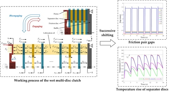
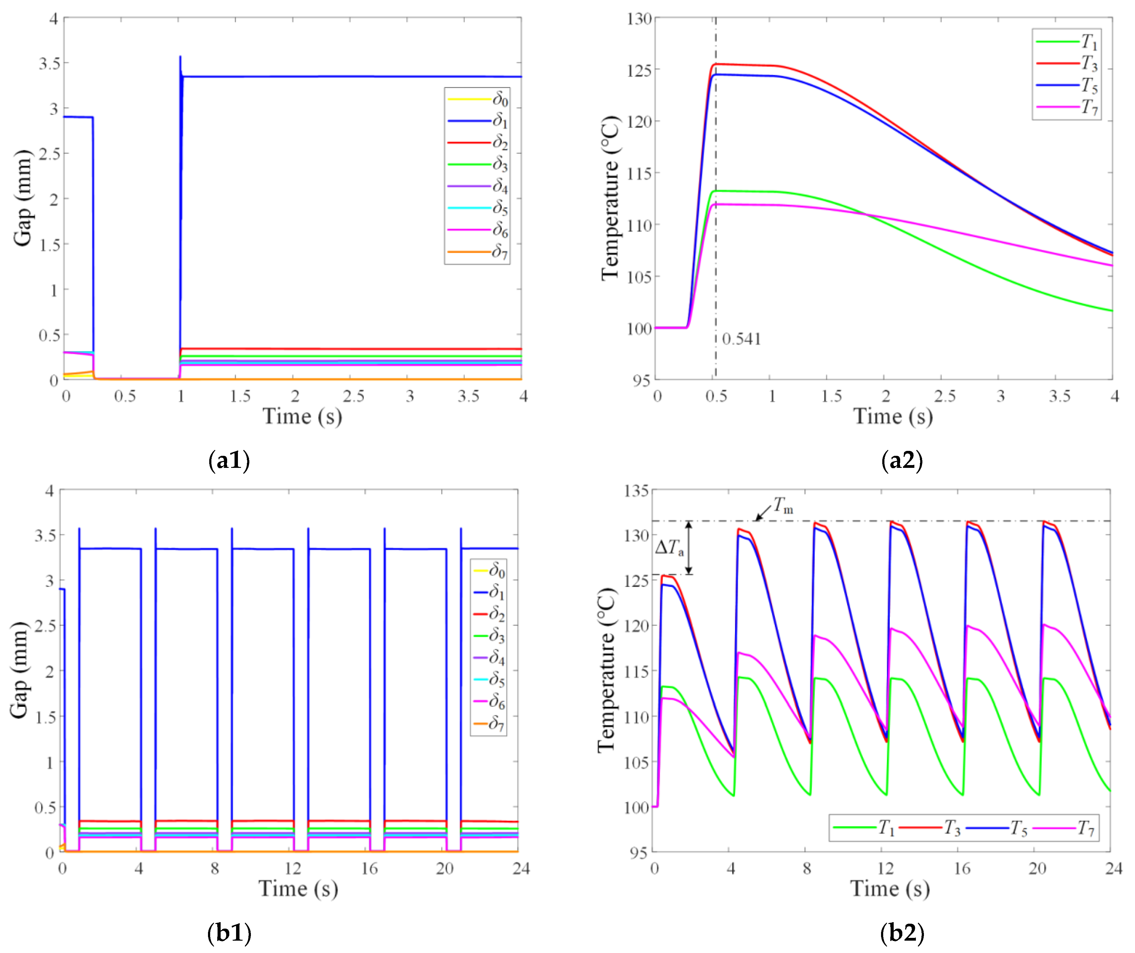
  • Because of the attenuation effect of the spline friction force on the applied pressure, the generated friction heat and disengaged friction pair gaps both decayed from the first to the last friction pair in sequence. Thus, both the temperature rise and temperature drop of the second separator disc near the piston were the largest.
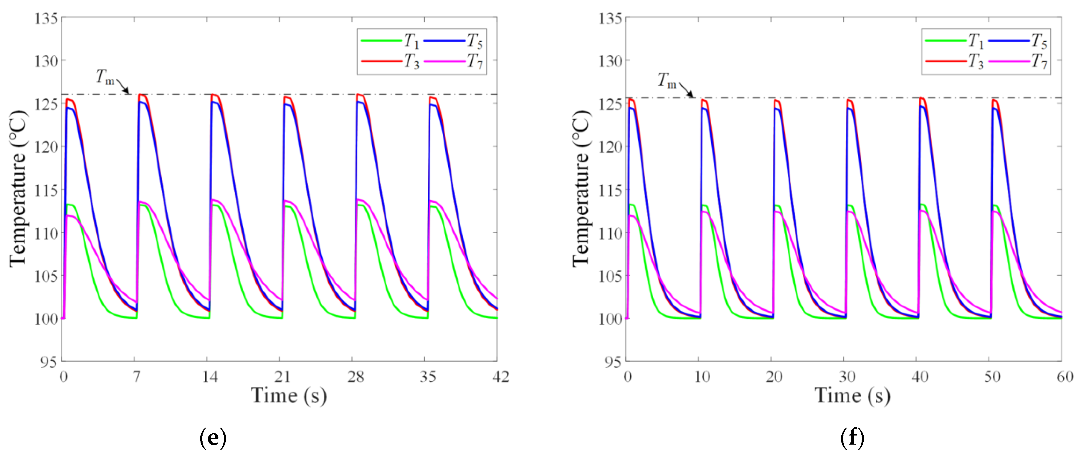
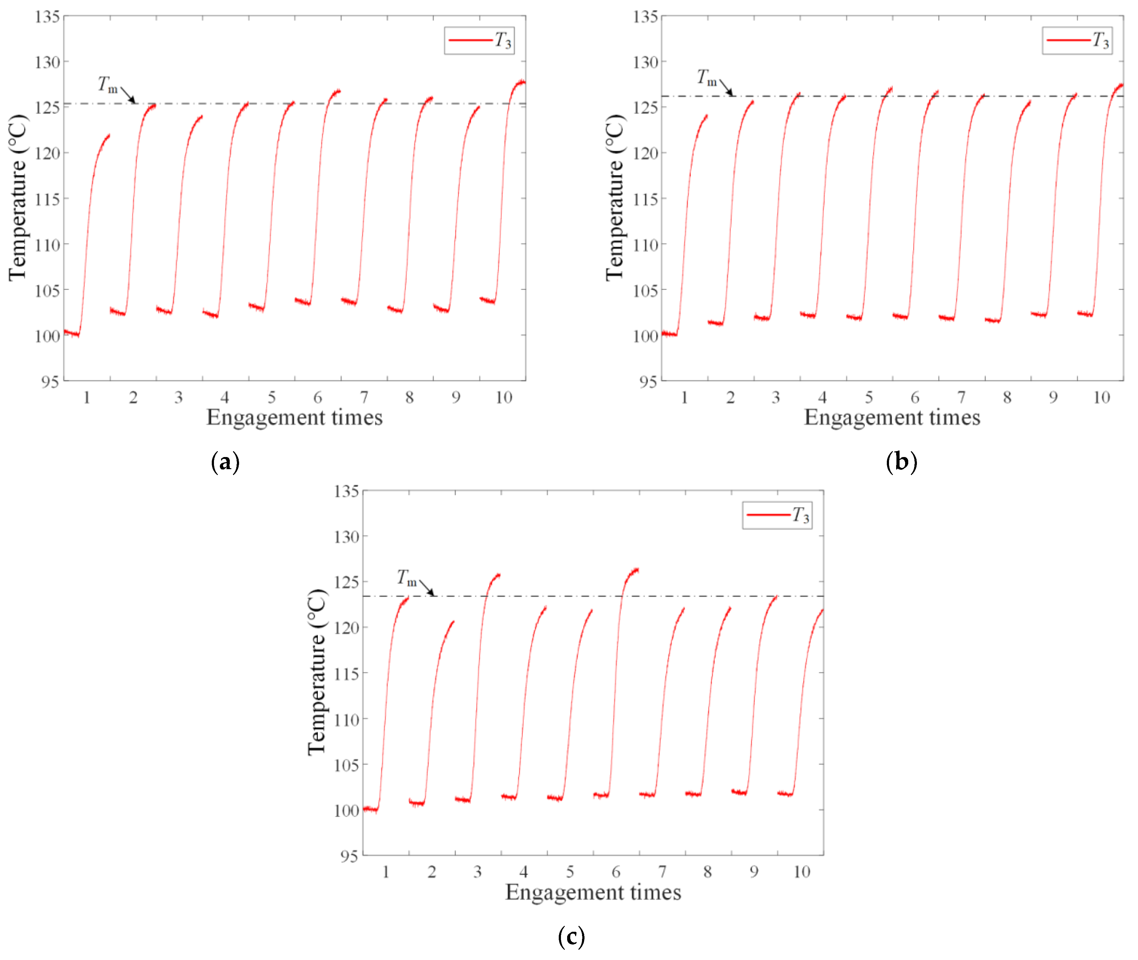
  • In the successive shifting condition, the convection heat transfer was enhanced with the expansion of the temperature difference between the separator disc and the lubrication oil. When the decreasing temperature rise equaled the increasing temperature drop, the maximum clutch temperature no longer increased.
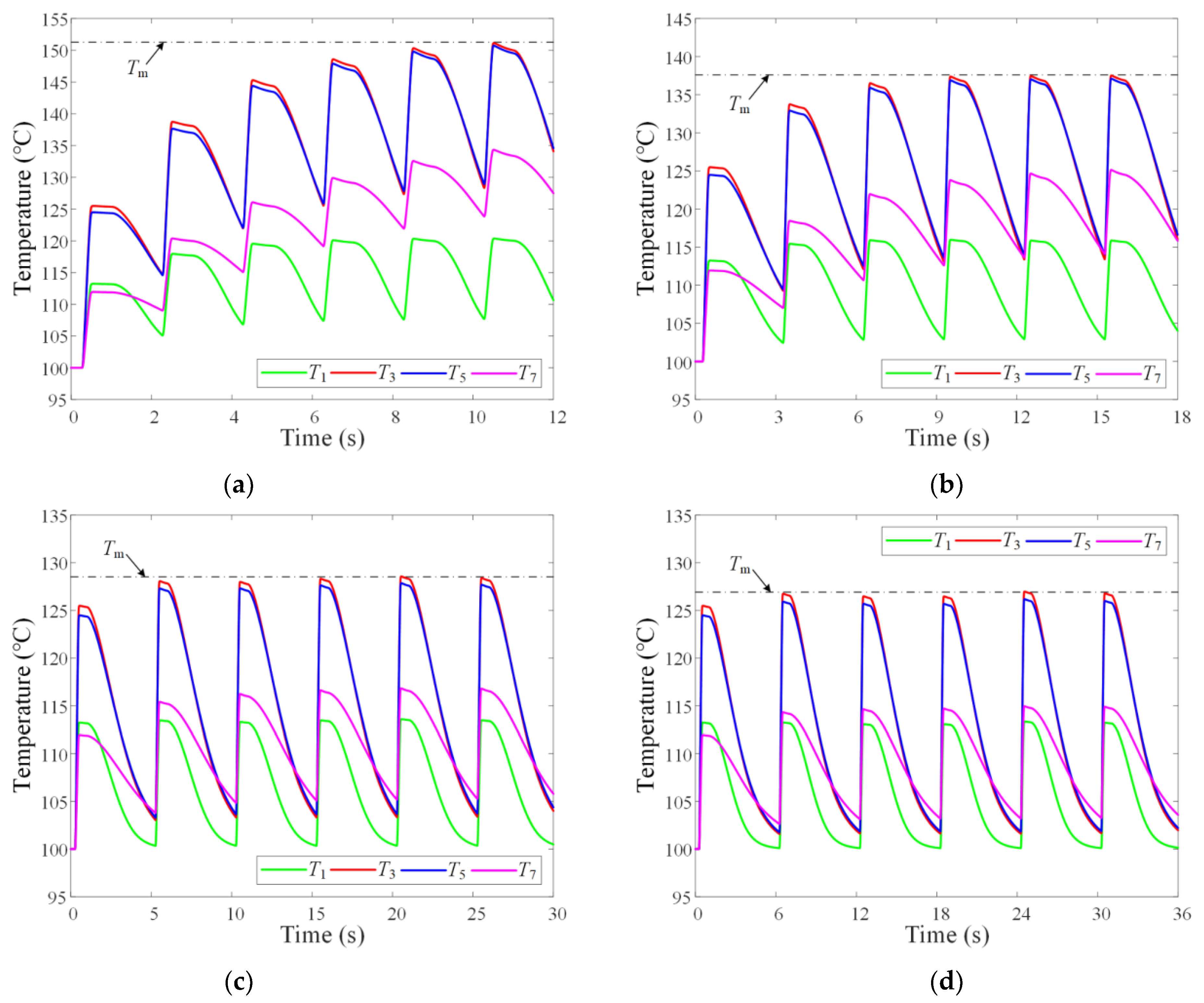
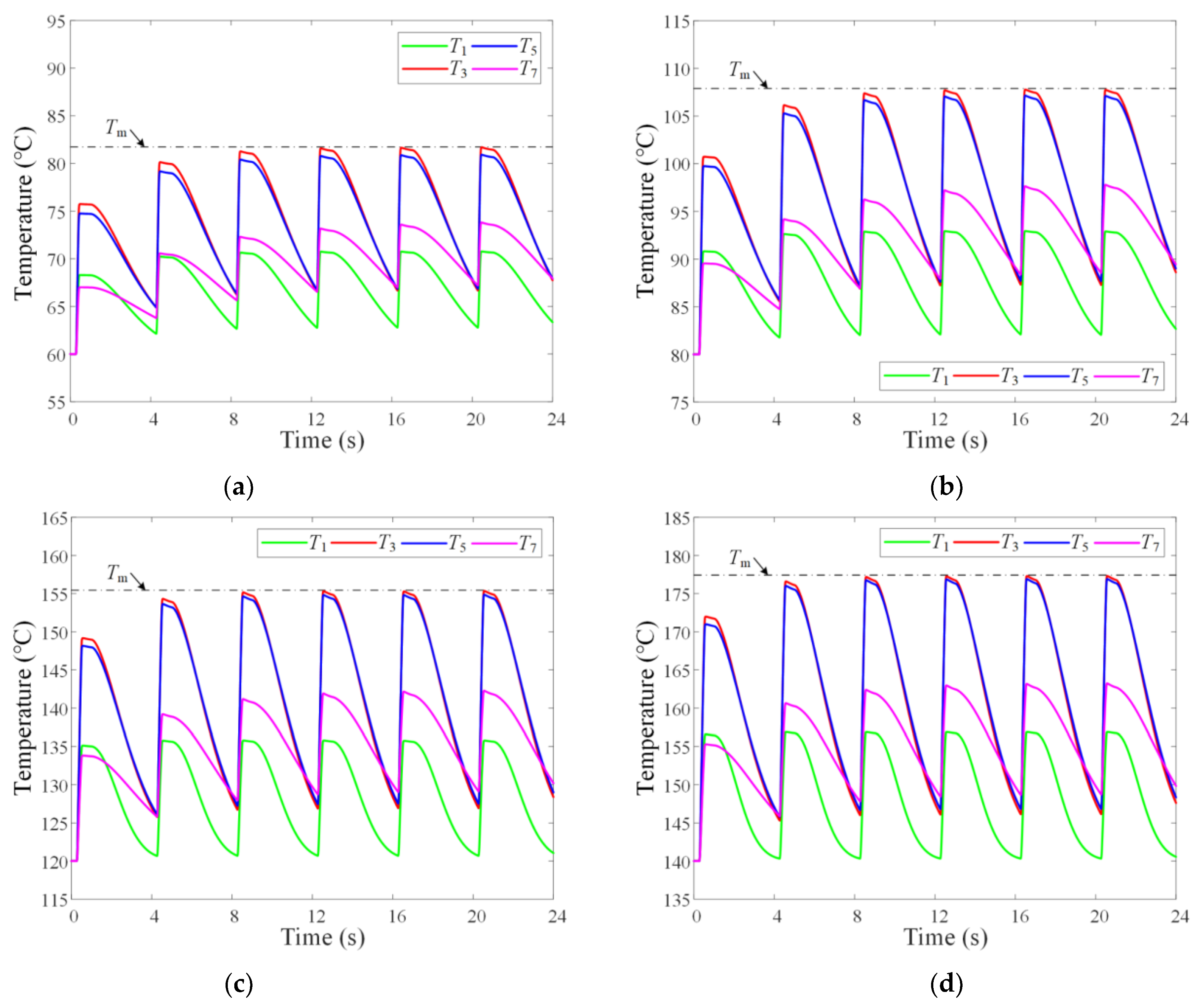
  • Because more heat was dissipated in the disengagement status with the increase of the shifting interval, the accumulated temperature rise decreased exponentially until zero. Moreover, with the increasing lubrication oil temperature, the efficiency of convection heat transfer declined; the temperature rise in a single engaging process increased, but the accumulated temperature rise was not enlarged due to the broadening second and third friction pair gaps.

Author Contributions

Conceptualization, B.M. and M.C.; data curation, L.Z.; formal analysis, B.M. and L.Y.; funding acquisition, B.M. and M.C.; investigation, L.Z.; methodology, L.Z.; project administration, M.C.; software, L.Z.; supervision, B.M.; validation, L.Z. and J.X.; visualization, L.Z.; writing—original draft, L.Z.; writing—review & editing, L.Z., L.Y., and Q.W. All authors have read and agreed to the published version of the manuscript.

Funding

This research was funded by the National Natural Science Foundation of China (Grant Nos. 52175037 and 51975047) and the China Postdoctoral Science Foundation (Nos. 2021M700422 and BX20220379).

Institutional Review Board Statement

Not applicable.

Informed Consent Statement

Not applicable.

Data Availability Statement

Not applicable.

Conflicts of Interest

The authors declare no conflict of interest.

Nomenclature

Arednon-groove area ratioToiltemperature of lubrication oil (°C)
cspecific heat capacity (J/(kg·°C))Tambient temperature (°C)
csdamping coefficient (N·s/m)vilinear velocity of inner annulus (m/s)
dmthickness of friction material (m)volinear velocity of outer annulus (m/s)
Diinner diameter (m) v ¯ average velocity of lubrication oil (m/s)
Doouter diameter (m)Vlinear velocity difference (m/s)
erecovery coefficientxdisplacement (m)
E effective Young’s modulus (Pa)velocity (m/s)
Fccontact force (N)acceleration (m/s2)
Fddamping force (N)Znumber of friction pairs
Ff, Fsspline friction force (N)αfpressure angle of inner spline (°)
Fimpactimpact force (N)αspressure angle of outer spline (°)
Fkreturn spring force (N)βasperity radius (m)
Fpcontrol oil pressure force (N)εspatial step (m)
Fvhydrodynamic force (N)δgap of friction pair (m)
hnominal oil film thickness (m)ωf1angular velocity of separator disc (rad/s)
h ¯ T average oil film thickness (m)ωf2angular velocity of friction disc (rad/s)
Hfdthickness of friction disc (m)Δωangular speed difference (rad/s)
Hsdthickness of separator disc (m)ηdynamic viscosity (Pa·s)
If2inertia of drive end (kg·m2)κplastic deformation coefficient
K0stiffness of impact (N/m)λthermal conductivity (W/(m·°C))
K contact coefficientμsplinespline friction coefficient
m0weight of piston (kg)ξlocal relative indentation (m)
m1weight of separator disc (kg)ρdensity (kg/m3)
m2weight of friction disc (kg)σstandard deviation of roughness (m)
MRresistance torque (N·m)τtime step (s)
MPmotor torque (N·m)ϕrpressure flow factor
nimpact coefficientϕf, ϕfsshear stress factors
Nasperity density (/m2)Ψpermeability (m2)
Papplied pressure (Pa)Subscripts
Riinner radius of friction pair (m)
Roouter radius of friction pair (m)fcCu-based friction material
Rfpitch radius of inner spline (m)ststeel material
Rspitch radius of outer spline (m)llubrication oil

References

  1. Bao, H.; Huang, W.; Lu, F. Investigation of engagement characteristics of a multi-disc wet friction clutch. Tribol. Int. 2021, 159, 106940. [Google Scholar] [CrossRef]
  2. Meng, F.; Xi, J. Numerical and experimental investigation of temperature distribution for dry-clutches. Machines 2021, 9, 185. [Google Scholar] [CrossRef]
  3. Yu, L.; Ma, B.; Chen, M.; Li, H.; Liu, J.; Zheng, L. Numerical and experimental studies on the characteristics of friction torque based on wet paper-based clutches. Tribol. Int. 2019, 131, 541–553. [Google Scholar] [CrossRef]
  4. Yu, L.; Ma, B.; Chen, M.; Xue, J.; Zhao, P. Variation mechanism of the friction torque in a Cu-based wet clutch affected by operating parameters. Tribol. Int. 2020, 147, 106169. [Google Scholar] [CrossRef]
  5. Li, W.; Huang, J.; Fei, J.; Cao, L.; Yao, C.; Wang, W. Simulation of the engagement of carbon fabric wet clutch: Analytical and experimental comparison. Tribol. Int. 2015, 90, 502–508. [Google Scholar] [CrossRef]
  6. Wang, Y.; Li, Y.; Liu, Y.; Zhang, W. Modeling and experimental research on engaging characteristics of wet clutch. Ind. Lubr. Tribol. 2019, 71, 94–101. [Google Scholar] [CrossRef]
  7. Wang, Y.; Yang, K.; Wu, X. Structural design and friction performance test of a new conical groove friction disks in wet clutch. Appl. Sci. 2021, 11, 7231. [Google Scholar] [CrossRef]
  8. Yu, L.; Ma, B.; Chen, M.; Li, H.Y.; Liu, J. Experimental study on the friction stability of paper-based clutches concerning groove patterns. Ind. Lubr. Tribol. 2020, 72, 541–548. [Google Scholar] [CrossRef]
  9. Li, W.; Huang, J.; Fei, J.; Cao, L.; Yao, C. Simulation and application of temperature field of carbon fabric wet clutch during engagement based on finite element analysis. Int. Commun. Heat Mass Transf. 2016, 71, 180–187. [Google Scholar]
  10. Ma, B.; Yu, L.; Chen, M.; Li, H.Y.; Zheng, L.J. Numerical and experimental studies on the thermal characteristics of the clutch hydraulic system with provision for oil flow. Ind. Lubr. Tribol. 2019, 71, 733–740. [Google Scholar] [CrossRef]
  11. Wu, J.; Ma, B.; Li, H.; Wang, L. The temperature field of friction disc in wet clutch involving the unconventional heat dissipation on the contact surface. Tribol. Trans. 2021, 64, 1–9. [Google Scholar] [CrossRef]
  12. Yang, L.; Ma, B.; Ahmadian, M.; Li, H.; Vick, B. Pressure distribution of a multidisc clutch suffering frictionally induced thermal load. Tribol. Trans. 2016, 59, 983–992. [Google Scholar] [CrossRef]
  13. Yu, L.; Ma, B.; Li, H.; Liu, J.; Li, M. Numerical and experimental studies of a wet multidisc clutch on temperature and stress fields excited by the concentrated load. Tribol. Trans. 2019, 62, 8–21. [Google Scholar] [CrossRef]
  14. Li, L.; Li, H.; Wang, L. Numerical analysis of dynamic characteristics of wet friction temperature fields. Adv. Mech. Eng. 2017, 9, 1–14. [Google Scholar] [CrossRef]
  15. Meng, Q.; Tian, Z.; Zhao, C. Non-uniform contact characteristics of the friction disc during the initial period of a braking process. J. Mech. Sci. Technol. 2018, 32, 1261–1268. [Google Scholar] [CrossRef]
  16. Bao, H.; Kong, W.; Hou, X.; Zhu, R. Analysis on temperature field of friction pair of aviation friction clutch based on different groove shapes of friction disk. J. Mech. Sci. Technol. 2021, 35, 3735–3742. [Google Scholar] [CrossRef]
  17. Grzes, P. Maximum temperature of the disc during repeated braking applications. Adv. Mech. Eng. 2019, 11, 1–13. [Google Scholar] [CrossRef]
  18. Bao, J.; Yin, Y.; Lu, L.; Liu, T. Tribological characterization on friction brake in continuous braking. Ind. Lubr. Tribol. 2018, 70, 172–181. [Google Scholar] [CrossRef]
  19. Yanar, H.; Purcek, G.; Demirtas, M.; Ayar, H.H. Effect of hexagonal boron nitride (h-BN) addition on friction behavior of low-steel composite brake pad material for railway applications. Tribol. Int. 2022, 165, 107274. [Google Scholar] [CrossRef]
  20. Pisaturo, M.; Senatore, A. Simulation of engagement control in automotive dry-clutch and temperature field analysis through finite element model. Appl. Therm. Eng. 2016, 93, 958–966. [Google Scholar] [CrossRef]
  21. Zhao, E.H.; Ma, B.; Li, H.Y. Numerical and experimental studies on tribological behaviors of Cu-based friction pairs from hydrodynamic to boundary lubrication. Tribol. Trans. 2018, 61, 347–356. [Google Scholar] [CrossRef]
  22. Yu, L.; Ma, B.; Chen, M.; Li, H.; Zhang, H.; Liu, J. Thermodynamic differences of different friction pairs in a multidisc clutch caused by spline friction: Numerical simulation and experimental verification. Tribol. Trans. 2019, 62, 724–736. [Google Scholar] [CrossRef]
  23. Zheng, L.; Ma, B.; Chen, M.; Yu, L.; Wang, Q. Influence of the lubrication oil temperature on the disengaging dynamic characteristics of a Cu-based wet multi-disc clutch. Appl. Sci. 2021, 11, 11299. [Google Scholar] [CrossRef]
  24. Lankarani, H.M.; Nikravesh, P.E. A contact force model with hysteresis damping for impact analysis of multibody systems. J. Mech. Des. 1990, 112, 369–376. [Google Scholar] [CrossRef]
Figure 1. Structure of the wet multi-disc clutch.
Machines 10 00576 g001
Figure 2. Axial force analysis for a wet multi-disc clutch.
Machines 10 00576 g002
Figure 3. Flow chart of the simulation.
Machines 10 00576 g003
Figure 4. Variations of dynamic parameters in a four-second working cycle. (a) Control oil pressure, return spring force, and motor torque. (b) Rotating speed of friction disc and friction torque.
Machines 10 00576 g004
Figure 5. Verifications of simulation data. (a) Torque and pressure. (b) Speed and temperature.
Machines 10 00576 g005
Figure 6. Variations of gaps and temperatures: (a1,a2) in the first working cycle; (b1,b2) in the six repeated working cycles.
Machines 10 00576 g006
Figure 7. Variation of temperatures at different shifting intervals: (a) 2 s; (b) 3 s; (c) 5 s; (d) 6 s; (e) 7 s; (f) 10 s.
Machines 10 00576 g007aMachines 10 00576 g007b
Figure 8. Experimental temperatures at different shifting intervals: (a) 10 s; (b) 14 s; (c) 18 s.
Machines 10 00576 g008
Figure 9. Variation of temperatures with different lubrication oil temperatures: (a) 60 °C; (b) 80 °C; (c) 120 °C; (d) 140 °C.
Machines 10 00576 g009
Table 1. Parameters of the simulation and test.
ParameterValueParameterValueParameterValue
Ared0.65m0/(kg)1β/(m)8 × 10−4
cs/(N·s/m)0.0466m1/(kg)0.25σ/(m)8.4 × 10−6
cst/(J/(kg·°C))487m2/(kg)0.32Ψ/(m2)2 × 10−12
cfc/(J/(kg·°C))536MR/(N·m)5 × 10−4μspline0.1
cl/(J/(kg·°C))2231N/(m−2)7 × 107λst/(W/(m·°C))45.9
dm/(m)5 × 10−4Ri/(m)0.06λfc/(W/(m·°C))9.3
E /(Pa)4.84 × 109Ro/(m)0.073λl/(W/(m·°C))0.3
Hfd/(m)2.5 × 10−3Toil/(°C)100ρst/(kg/m3)7800
Hsd/(m)2 × 10−3η/(Pa·s)0.0121ρfc/(kg/m3)5500
If2/(kg·m2)0.248ε/(m)5 × 10−4ρl/(kg/m3)875
Table 2. Disengaged gaps with different lubrication oil temperatures.
Toil/(°C)6080100120140
δ0/(mm)0.00240.00250.00260.00270.0028
δ1/(mm)3.38733.36643.34743.30043.2221
δ2/(mm)0.32520.33310.33920.35700.3845
δ3/(mm)0.24880.25430.25850.26950.2884
δ4/(mm)0.19960.20300.20640.21390.2271
δ5/(mm)0.17740.17990.18270.18880.1993
δ6/(mm)0.15710.15850.16060.16520.1730
δ7/(mm)0.00240.00250.00260.00270.0028
Publisher’s Note: MDPI stays neutral with regard to jurisdictional claims in published maps and institutional affiliations.

