Article

An IPMSM Control Structure Based on a Model Reference Adaptive Algorithm

1
College of Mechanical Engineering and Automation, Huaqiao University, Xiamen 361021, China
2
State Key Laboratory of Fluid Power and Mechatronic Systems, Zhejiang University, Hangzhou 310027, China
3
Fujian Key Laboratory of Green Intelligent Drive and Transmission for Mobile Machinery, Xiamen 361021, China
*
Author to whom correspondence should be addressed.
Machines 2022, 10(7), 575; https://doi.org/10.3390/machines10070575
Submission received: 10 June 2022 / Revised: 13 July 2022 / Accepted: 14 July 2022 / Published: 17 July 2022
(This article belongs to the Section Electrical Machines and Drives)

Abstract

:
Traditional construction machinery has the disadvantages of low energy efficiency and poor emissions, which do not meet the requirements of environmentally friendly industrial development. Electric construction machinery has attracted more and more attention because of its advantages of zero emissions and high energy efficiency, which are considered to be important factors in the future development of construction machinery. Preliminary attempts to introduce electric motors into construction machinery usually only adopt the motor for simulating the working mode of the engine, with it providing power for the system. Because the output power of the motor needs to be matched with the actual load through the transmission of the hydraulic torque converter, it is difficult to maximize the advantages of high energy efficiency for the electric drive. This paper studied the direct drive technology within electric construction machinery and presents a model reference adaptive algorithm (MRAA) based on maximum torque per ampere (MTPA)-vector control of an internal permanent magnet synchronous motor (IPMSM). The reference motor model was established, and the real-time dynamic reference value of the motor was obtained based on a model with the motor voltage and current as inputs. Simulations based on MATLAB/Simulink verified the feasibility of this control method. The results indicate that the MRAA can identify the motor flux linkage value and the d-q axis inductance within 50 ms in real time, with the error controlled within 2%. Additionally, when the motor operates at low speed, compared with the traditional MTPA algorithm under fixed-parameter control, the starting torque ripple of the IPMSM control method based on reference model adaptation was reduced to 23.8%, which proves that the MRAA can achieve good low-speed response characteristics and stability.

1. Introduction

Traditional construction machinery uses the engine as the power source; due to the large fluctuation range of the working load, the hydraulic torque converter is generally used to understand the transformation of speed and torque. The transmission efficiency of the hydraulic torque converter is generally only 20% to 80%, and the heavier the load, the lower the transmission efficiency, which makes it difficult to improve the energy utilization of construction machinery and aggravates the problem of exhaust emissions [1,2].
The electrification of construction machinery uses the motor as the power source, which can achieve zero emissions and significantly improve the energy efficiency of construction machinery. It is considered to be one of the main development directions for construction machinery [3,4,5]. Electrification technology has been widely used in the field of automobiles. However, the working conditions of construction machinery are essentially different and more complex from that of automobiles. The electrification of construction machinery needs to be reconsidered.
Lots of research has been carried out on the electrification of construction machinery. Canceling the hydraulic torque converter and using the electric motor combined with the transmission to directly drive the walking mechanism can effectively improve the efficiency of the walking transmission system [6]. However, as mentioned above, traveling construction machinery often needs the transmission system to work in a low-speed and high-torque situation or even under locked rotor conditions. The traditional motor control method makes it difficult to ensure the controllability of motor torque under a low-speed state [7,8,9,10]. Therefore, it is necessary to carry out further research on the control method of the motor under low-speed driving conditions for the walking transmission system [11].
Common, permanent magnet synchronous-motor control methods mainly utilize a constant voltage-frequency ratio control, vector control, direct torque control, and intelligent control based on vector control or direct torque control. Vector control and direct torque control are suitable for a wide range of motor working conditions and achieve good control performance. At present, vector control has become the most widely used control strategy, which is mainly divided into id = 0 control and MTPA control. This paper studies the intelligent vector control algorithm based on the basic MTPA control. The research on the control for the low-speed performance of permanent magnet synchronous motors (PMSM) is mainly based on motor state parameters and structure parameters. Based on the motor state parameters, Djeriou et al. proposed an original control method based on the grey wolf (GW) algorithm, which quickly found the input control physical quantity to minimize speed fluctuation by combining the advantages of the fast optimization process of the GW optimizer and carried out the actual test verification. The results showed that this method can greatly reduce the low-speed torque ripple of the motor [12,13]. Elsonbaty et al. proposed a control strategy for hybrid excitation PMSM. The simulation showed that the control strategy can reduce the torque ripple when the motor starts at a low speed without considering its parameters [14,15]. Zhu et al. proposed a control algorithm for low-speed motor dead-time compensation based on a combination of a neural network band-pass filter and an extended Kalman filter. Through comparative experiments, it was verified that the algorithm can effectively reduce the harmonic pulsation generated by low-speed motor operation and improve the utilization rate of the bus voltage [16]. Fu et al. proposed a sliding mode control algorithm based on vector control. Through comparative experiments, it was verified that the algorithm can effectively improve the anti-interference ability of the motor in the low-speed area of the motor [17].
Based on the structural parameters of the motor, Bobtsov et al. proposed a stator flux observer and dead-load torque estimation method for nonsalient PMSM, which identified the stator winding flux value of the motor through the combination of an LTI filter and linear regression and then combined this with the actual controls to reduce the low-speed torque ripple and enhance the low-speed running stability of the motor [18,19,20,21]. Cui et al. proposed a real-time estimation algorithm of all the parameters of a permanent magnet synchronous motor based on a stator-current ripple model, which realized the self-parameter identification of the motor under low-speed conditions and verified via simulation that this algorithm can enhance the stability of a motor under low-speed operation [22,23,24,25,26]. To sum up, at present, in the research of the low-speed performance of motors based on the structural parameters of the motor, most scholars used the state quantity in the process of motor operation to observe the physical parameters of the motor and then combined this with the basic direct torque control or vector control to reduce the torque ripple and overshoot of low-speed motor.
This paper studies the methods to improve the motor driving performance of walking construction machinery under low-speed and high-load torque conditions. A model reference adaptive algorithm (MRAA) is proposed for internal PMSM (IPMSM) based on the vector control of maximum torque per ampere (MTPA). Compared with traditional vector control and other intelligent control, the MRAA proposed in this paper can fully consider the physical quantities in the dynamic operation of a motor and then identify the motor’s parameters in real time to optimize the real-time operating performance of the motor. By establishing the motor reference model and taking the motor voltage and current as the input physical quantity, according to the reference adaptive mathematical model, the parameters of the motor model can be dynamically adjusted with the external interference. Simulation research is carried out to verify the rationality and control effect of the proposed MRAA for IPMSM.

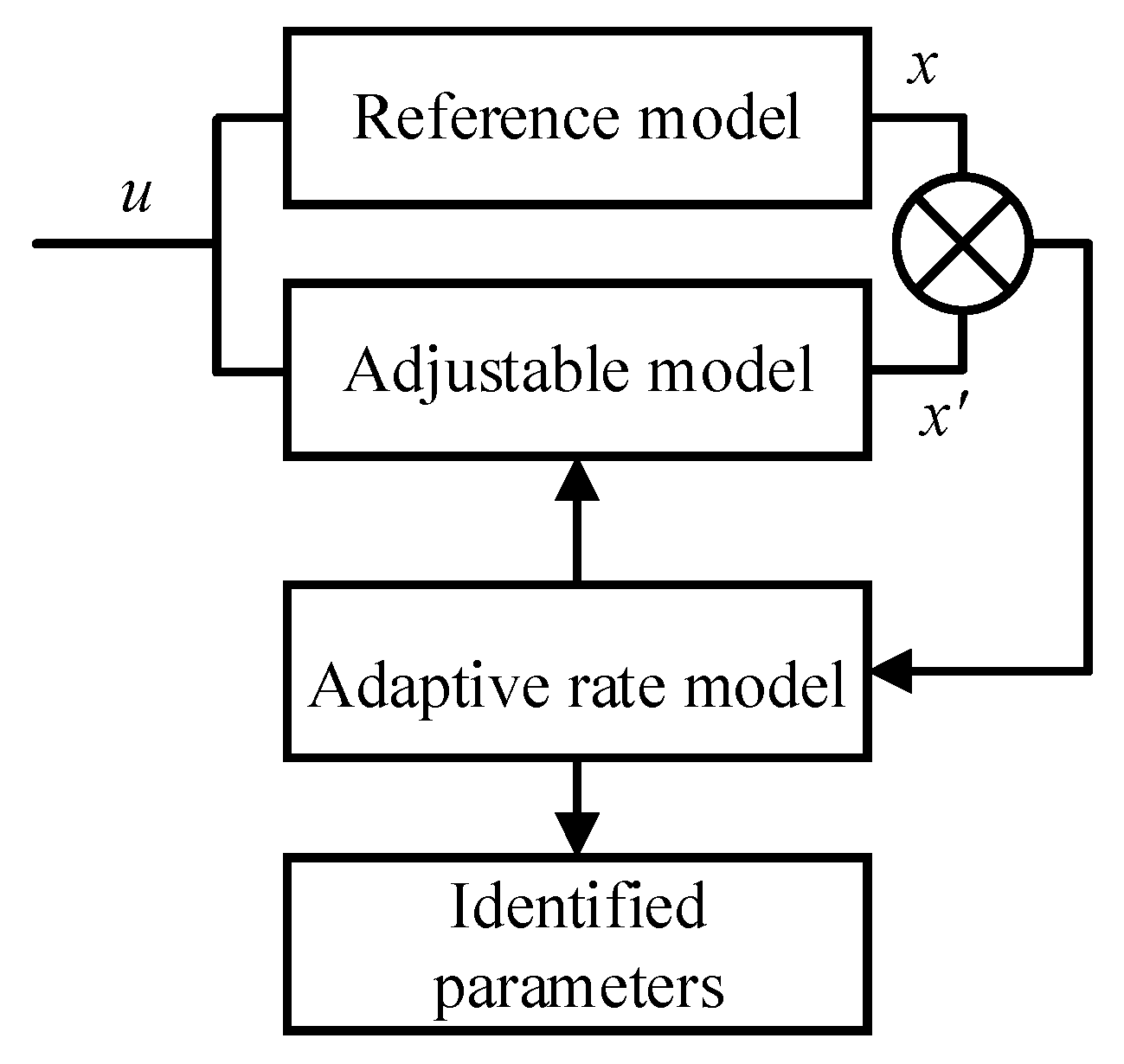
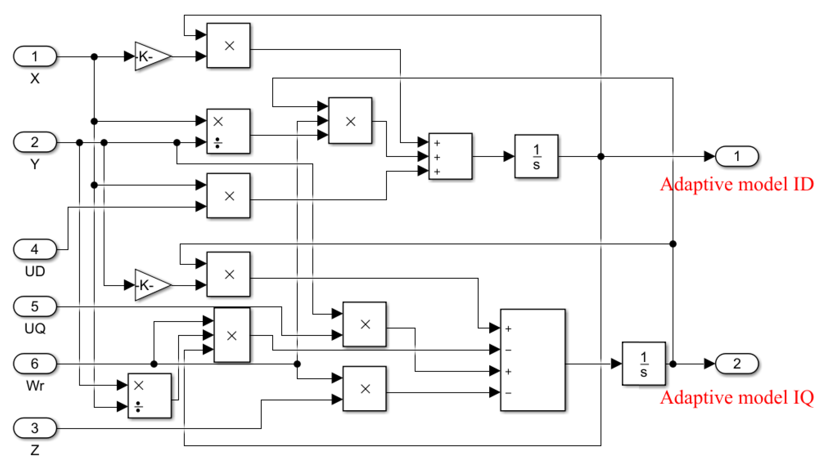
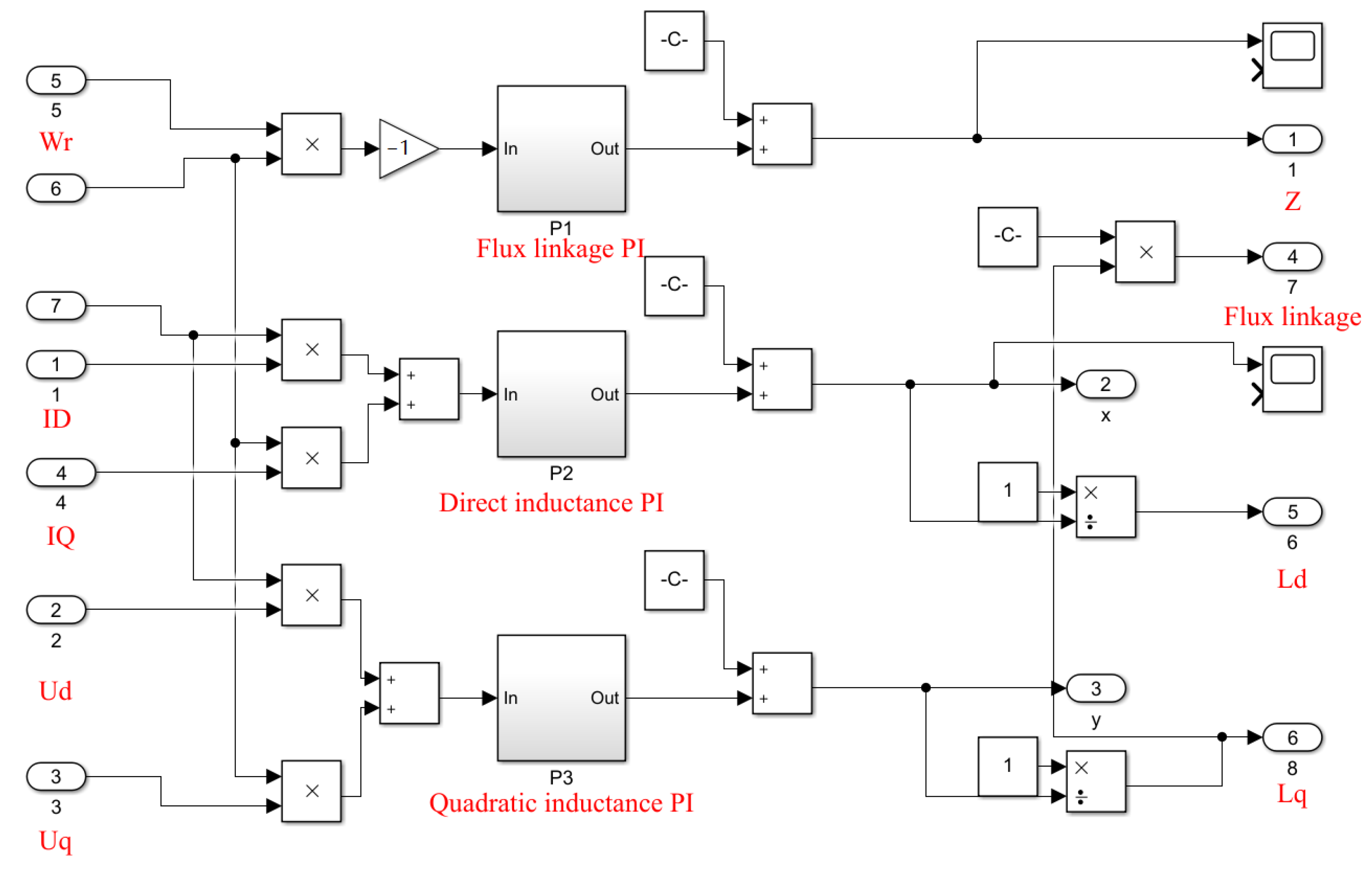
2. Principle of MRAA for Parameter Identification

2.1. MRAA for IPMSM

The MRAA is able to analyze a physical signal by establishing a mathematical model, and then converges the reduced parameters to be as close to the set true value as possible. The MRAA mainly consists of the reference model, adjustable model, and adaptive rate model, as shown in Figure 1. The reference model generally refers to the mathematical model of the system under the idealized condition, which has the most ideal system parameters and system test conditions. The adjustable model refers to the mathematical model system established according to the actual situation. Its inputs are physical quantities such as motor voltage and current, but the internal mathematical model will change its model parameters with external disturbances and other random changes to change the output results of the model. The adaptive rate model takes the output difference between the reference model and the adjustable model as the input and uses the appropriate theory to design the model, such as PI-adaptive rate design, so that the module outputs the ideal parameter identification results. The biggest feature of the system is that the ideal output of the main controlled object of the system is determined by the output of the reference model.
MRAA design can be divided into three parts, for which adaptive rate design is the most important part of the whole system. Adaptive rate design is generally applied to nonlinear situations, so the quality of the whole module design directly determines whether the stability of the whole system meets the requirements. The adaptive rate design method will be described below. There are three common adaptive rate design methods: local parameter optimization, Lyapunov stability theory, and Popov stability theory. The local parameter optimization method is simple and easy to understand, and the amount of calculation is small, but it cannot ensure the closed-loop control stability of the system, so it is only suitable for relatively simple scenarios and cannot be applied to occasions requiring high control accuracy. The design of the adaptive rate model based on Lyapunov stability theory is complex; it is difficult to establish the principle equation of parameter identification for this model, and the amount of calculation is too large to be applied in practice. The design of the adaptive rate model based on Popov stability theory is relatively simple, and its principle equation is easy to establish, with the amount of calculation required being small. Among them, Hong Dong Gai et al. designed the adaptive rate part of parameter identification based on Lyapunov stability theory and then proposed a new model-reference adaptive control based on PID control [26]. In this paper, the adaptive rate design of motor parameter identification based on Popov hyperstability theory is adopted, which is simpler, less computationally intensive, and has good stability. Therefore, to make the whole MRAA control system more suitable for practice so that the whole system can better serve the high-precision field contract, this version is easier to realize, so the MRAA adaptive rate model was designed based on Popov stability theory.

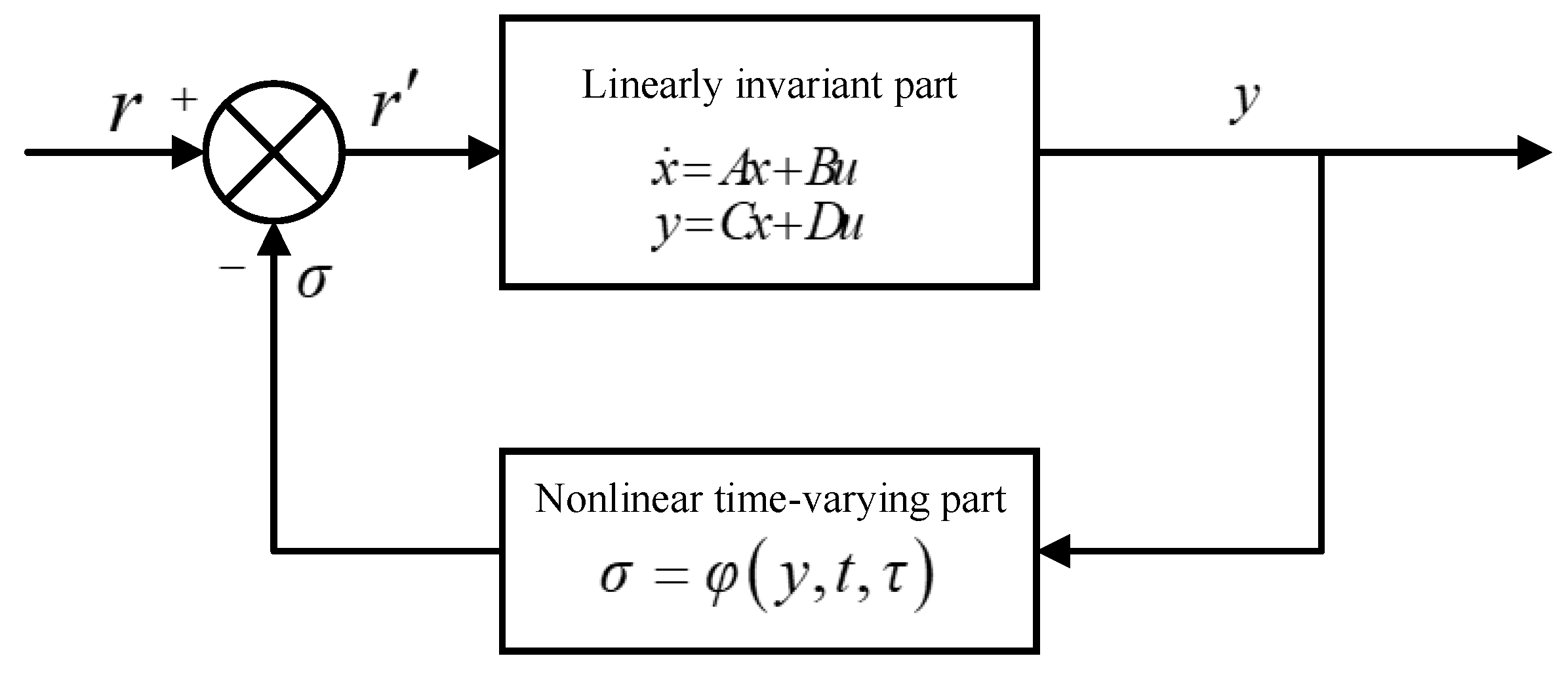
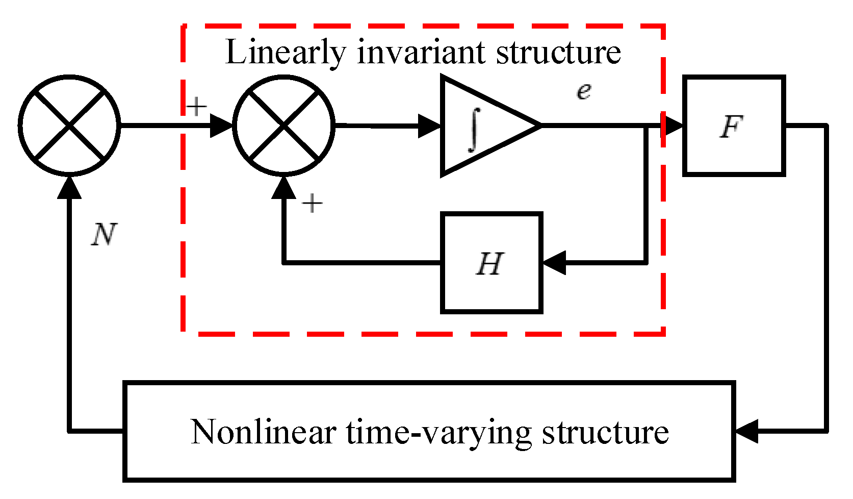
2.2. Popov Stability Judgment

Popov hyper stability theory mainly refers to the stability of the integral value of the input–output product of the system under particular constraints. In Figure 2, the structural block diagram of Popov hyper stability theory is illustrated. The system consists of two parts: a forward channel and a feedback channel. The forward channel is a linear constant part, and the feedback channel is a nonlinear part of the system, and this part can be constant or time-varying. The above two channels combine to form the closed-loop system in the figure [27,28]. In addition, in order to reduce the amount of calculation of the mathematical model and make the design process of the model simpler, we choose Popov hyperstability theory to design the adaptive rate of the MRAA. Compared with Lyapunov stability theory, Popov hyperstability theory does not need to choose the Lyapunov function, which reduces the difficulty of model design and is more flexible for application.
If the external input of the positive channel of the system r is equal to 0, the external input of the system is equal to the negative value of the feedback output of the feedback channel, i.e., r = σ . Therefore, to make the whole adaptive rate system achieve better stability, the input and output of the transmission part of the feedback channel should comply with Popov inequality, as shown in Equation (1):
Ψ ( t 0 , t 1 ) = 0 1 σ T ( τ ) y ( τ ) d τ r 0 2 t 1 t 0
where Ψ(t0, t1) is the function of Popov hyper stability theory. σ is the feedback of Popov hyper stability theory. y is the output of Popov hyper stability theory. r0 is the input of the Popov hyper stability theory at t0. t0 and t1 are different times.
If the whole adaptive rate system is stable, there must be a constant ξ, λ which are greater than 0, so that the state variable of the linear part of the forward channel satisfies the following inequality:
x ( t ) < ξ [ x ( t 0 ) + λ ]   t t 0
where ξ, and λ are constants.
At this time, the state variable function x(t) is infinitely close to 0.
From the above analysis, it can be seen that the whole adaptive rate closed-loop system needs to meet the following two conditions to have super stability:
(1) The transfer function matrix of the linear part of the forward channel shall be a positive real matrix, which can be expressed as:
G ( s ) = D + C ( s I A ) 1 B
where G(s) is the transfer function matrix of the linear part of the forward channel of Popov hyper stability theory. A, B, C, D, and I are constant matrices, respectively.
(2) The nonlinear part of the feedback channel satisfies Popov inequality.

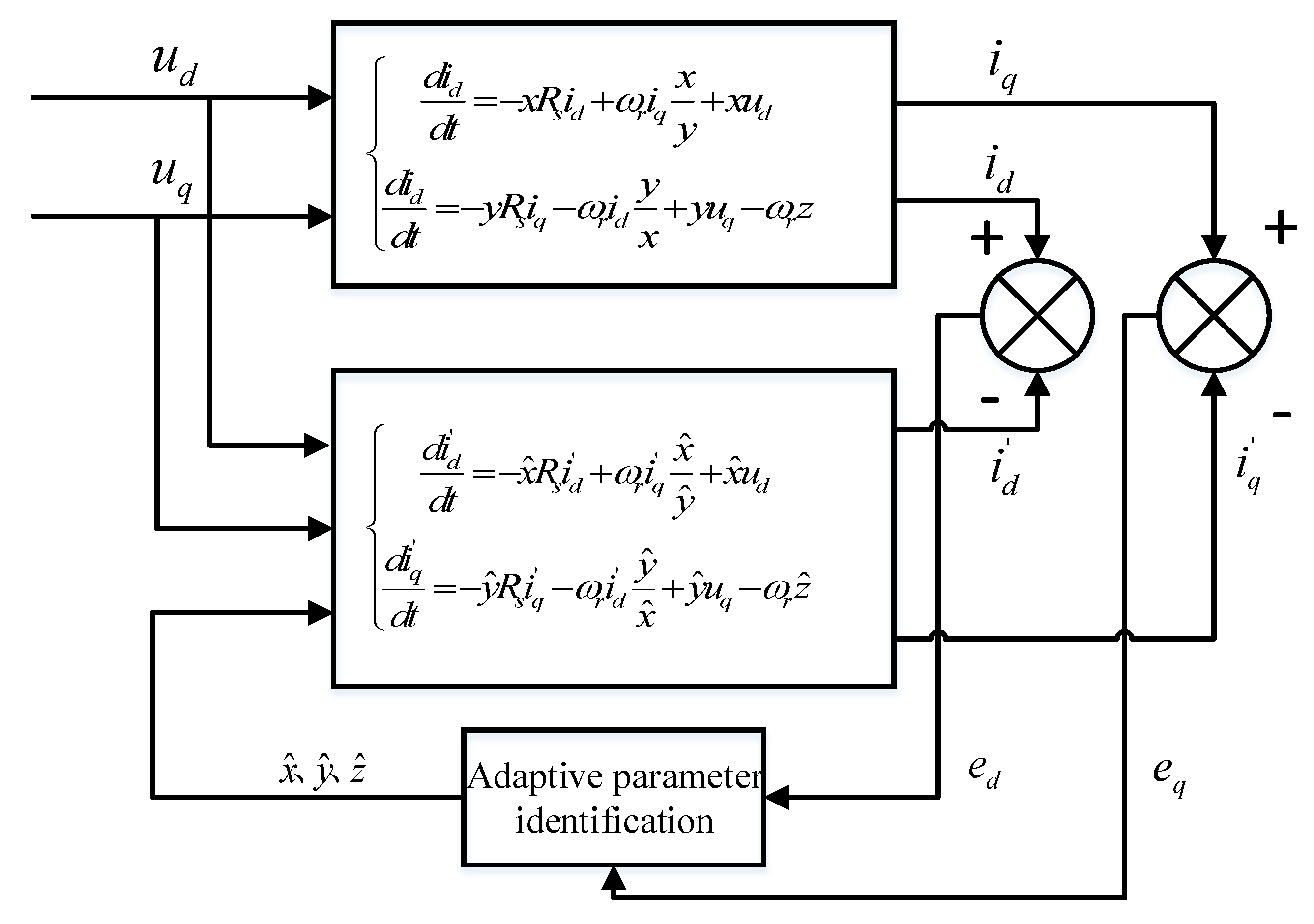
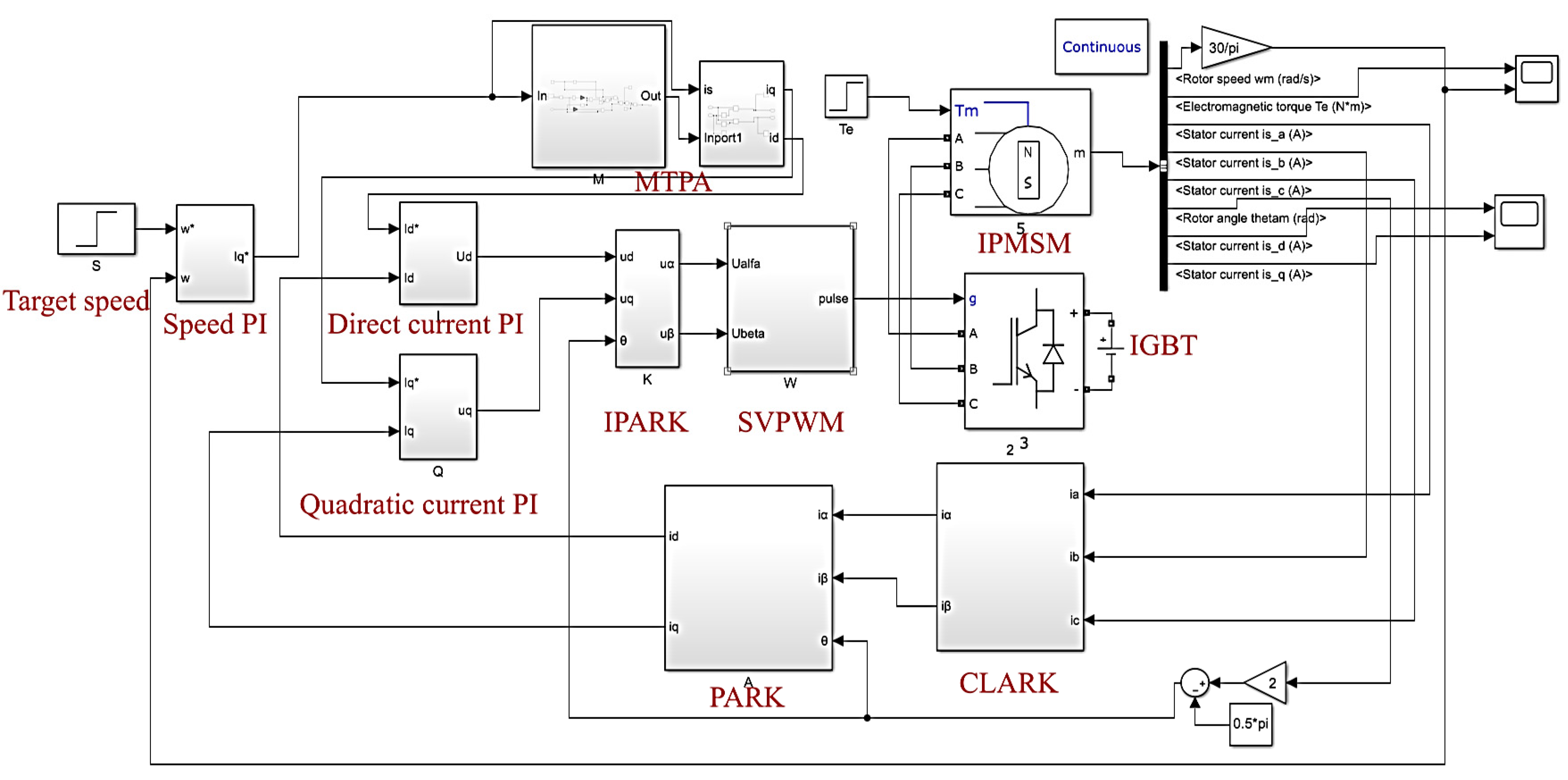
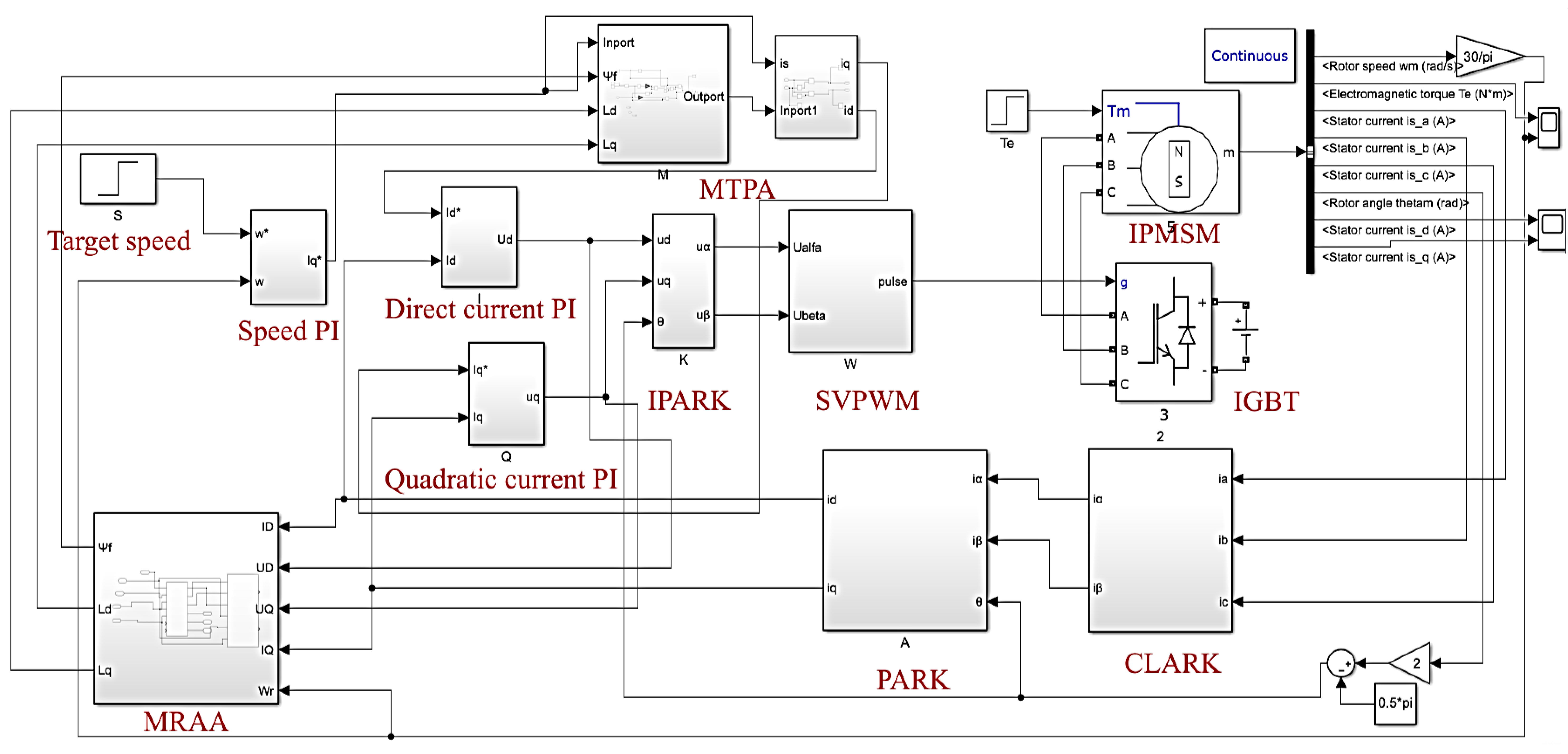
3. IPMSM Control Based on the MRAA

The actual permanent magnet synchronous motor is a nonlinear time-varying system. To facilitate the analysis and research of the mathematical model of the control algorithm proposed in this paper, the following assumptions are made:
(1)
The three-phase windings of the stator are symmetrical, with a space difference of a 120° electrical angle;
(2)
Ignoring the influence of the saturation of the motor magnetic circuit and the loss of the iron core, the motor magnetic circuit is regarded as a linear system;
(3)
Ignoring the high-order harmonics, the stator potential changes according to sinusoidal law, and the magnetic field generated by the stator current in the air gap is distributed according to sinusoidal law;
(4)
The winding damping of the rotor can be ignored.
On the basis of the above assumptions, the mathematical model of the permanent magnet synchronous motor in the three-phase stationary coordinate system can be obtained.
(1) Voltage equation
[ u A u B u C ] = [ R A 0 0 0 R B 0 0 0 R C ] [ i A i B i C ] + d d t [ φ A φ B φ C ]
where u A , u B , and u C are the phase voltages; R A , R B , and R C are the motor stator windings; i A , i B , and i C are the stator winding phase currents and φ A , φ B , and φ C are the motor stator flux linkages.
(2) The flux linkage equation
[ φ A φ B φ C ] = [ L AA L AB L AC L BA L BB L BC L CA L CB L CC ] [ i A i B i C ] + [ c o s   θ c o s ( θ 120 ° ) c o s ( θ + 120 ° ) ] φ f
where   φ f is the permanent magnet flux linkage of the rotor, L AA , L BB , and L CC are the self-inductance coefficients of the motor stator winding, and L AB , L BA , L CA , L AC , L BC , and L CB are the mutual inductance coefficients of the motor stator winding.
(3) Mechanical equation of motion:
J d ω m d t = T e T L B ω m
where T e is the electromagnetic torque, B is the friction coefficient, and T L is the load torque.
(4) Electromagnetic torque equation of motor:
T e = 3 2 p φ f [ 1 + ( L d L q ) i d ] i q
where   p is the number of poles of the motor.
The above is the mathematical model of the permanent magnet synchronous motor in the three-phase static coordinate system. Because there are a lot of coupling relationships between the physical quantities in the motor equation, and in order to simplify the algorithm analysis process, CLARK and PARK transformations were carried out under the principle of power invariance; the voltage and current equations of the motor in the dq axis rotating coordinate system can thus be obtained.
According to the stator winding voltage equation of the mathematical model for IPMSM, the stator winding equation can be expressed as:
{ d i d d t = R s L d i d + ω r i q L q L d + u d L d d i q d t = R s L q i q ω r i d L d L q + u q L q ω r φ f L q
where id and iq are the d-q components of the stator current vector, respectively. Rs is the resistance of the stator phase winding. Ld and Lq are the stator inductances transformed to the d-axis and q-axis of the reference frame system. ud and uq are the d-q components of the stator voltage vector supplying the stator phase winding. wr is the electric rotary speed of the rotor. φ f is the flux linkage of the IPMSM.
According to Equation (4), the d-q axis inductance L d , L q , and flux linkage φ f of the IPMSM are coupled with the motor stator current. Therefore, in the torque control system designed based on the MRAA, the current equation of the IPMSM can be selected as the reference model of the MRAA.
Assuming that x = 1 L d , y = 1 L q , z = φ f L q , using Equation (4), the voltage balance equation of the d-q axis can be obtained as:
{ d i d d t = x R s i d + ω r i q x y + x u d d i d d t = y R s i q ω r i d y x + y u q ω r z
Using Equation (5), the adjustable model of the MRAA can be obtained by replacing the real value with the estimated value of the parameters involved in the equation and expressed as:
{ d i d d t = x ^ R s i d + ω r i q x ^ y ^ + x ^ u d d i q d t = y ^ R s i q ω r i d y ^ x ^ + y ^ u q ω r z ^
where x, y, and z are the actual parameter values of the IPMSM, respectively. x ^ , y ^ , and z ^ are the identification parameter values, respectively. i d is the identification value for i d . i q is the identification value for i q .
After the design of the mathematical model for the reference model and the adjustable model was completed, the mathematical model of the adaptive rate model needed to be designed. The design of the adaptive rate model is based on the fact that the difference between the output of the reference model and the adjustable model meets the Popov hyper stability theory. Therefore, the difference between the reference model and the adjustable model needed to be analyzed. From Equations (5) and (6), the following equation can be deduced:
d d t [ e d e q ] = [ x R s ω r x y ω r y x y R s ] [ e d e q ] + [ x ^ R s x R s ω r x y ω r x ^ y ω r y ^ x ^ ω r y x y ^ R s y R s ] [ i d i q ] + [ x ^ x 0 0 y y ^ ] [ u d u q ] + ω r [ 0 z ^ z ]
For the equation e d = i d i d , e q = i q i q , assuming that:
P = [ x ^ R s x R s ω r x y ω r x ^ y ω r y ^ x ^ ω r y x y ^ R s y R s ]
Q = [ x ^ x 0 0 y y ^ ]
c = ω r [ 0 z ^ z ] ,   î = [ i d i q ]
u = [ u d u q ] , e = [ e d e q ] , H = [ x R s ω r x y ω r y x y R s ]
Equation (7) can be simplified as:
d e d t = H e + P î + Q u + c
The adaptive rate model design consists of the linear part of the forward channel and the nonlinear part of the feedback channel. According to Equation (12), the adaptive rate model of the MRAA, applicable to IPMSM, can be created as shown in Figure 3. Where F is an identity matrix, which can convert the output of the forward channel accordingly. The nonlinear time-varying module is the derivative equation of the motor current difference between the motor adjustable model and the reference model, established based on the MRAA, that is, the nonlinear part of the model error state equation, where N =   P î + Q u + c .
As shown in Figure 3, the transfer function matrix of the forward channel of the adaptive rate system conforms to the condition of a positive real matrix. Therefore, to ensure the good stability of the whole adaptive rate system, the nonlinear part of the feedback system should meet the Popov integral inequality mentioned in Equation (1), and Equation (12) can be brought into the Popov integral inequality and deduced as:
η ( 0 , t 1 ) = 0 t 1 e T ( P î + Q u + c ) d t = 0 t 1 e T P î d t + 0 t 1 e T Q u d t + 0 t 1 e T c d t γ 0 2
where η(t0, t1) is the function of the Popov hyper stability theory for this IPMSM.
Finally, Equation (13) is solved, and the definable adaptive rates x ^ , y ^ , and z ^ can be expressed as:
x ^ = K i 1 0 t [ ( i d i d ) i d + ( i q i q ) i q ] d τ + K p 1 [ ( i d i d ) i d + ( i q i q ) i q ] + x ^ ( 0 ) y ^ = K i 2 0 t [ ( i d i d ) u d + ( i q i q ) u q ] d τ + K p 2 [ ( i d i d ) u d + ( i q i q ) u q ] + y ^ ( 0 ) z ^ = [ 0 t K i ω r ( i q i q ) d τ + K p ω r ( i q i q ) ] + z ^ ( 0 )  

4. Simulation Research

4.1. Model Construction

As mentioned above, the MRAA established by IPMSM based on Popov hyper stability theory is now analyzed in detail. The reference model, adjustable model, and parameter adaptive rate equation of the MRAA were obtained. The schematic diagram of parameter identification based on the MRAA is shown in Figure 4.
According to the MRAA parameter identification system established by IPMSM based on Popov hyper stability theory, the reference model of the system is itself the mathematical model of the electric motor current. From Figure 4 (of parameter identification, the mathematical model of the adjustable model, and parameter adaptive rate), the reference model, adjustable model, and simulation model for the parameter-adaptive rate were established in Matlab/Simulink, as shown in Figure 5, Figure 6 and Figure 7.
The integrated control model of the MRAA for the vector control system for IPMSM was built in Matlab/Simulink. By combining the MRAA reference model, MRAA adjustable model, and the MRAA adaptive rate model, the IPMSM-MRAA parameter-identification system model based on Popov hyper stability theory was built in Matlab/Simulink and is shown in Figure 8.
The internal parameters of the IPMSM in the model are shown in Table 1:

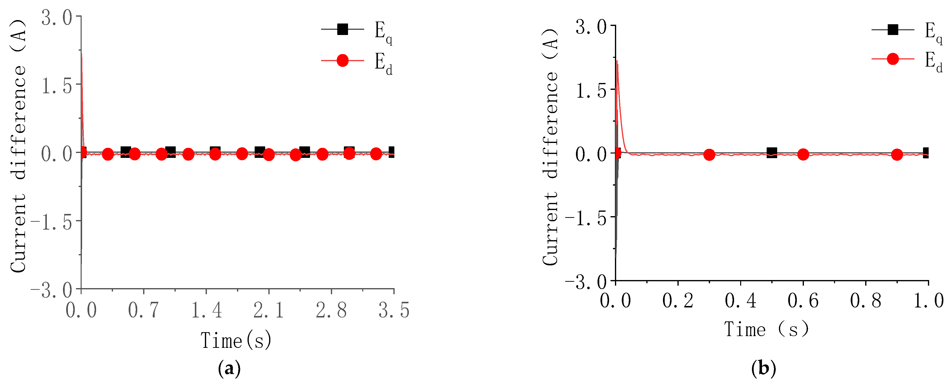
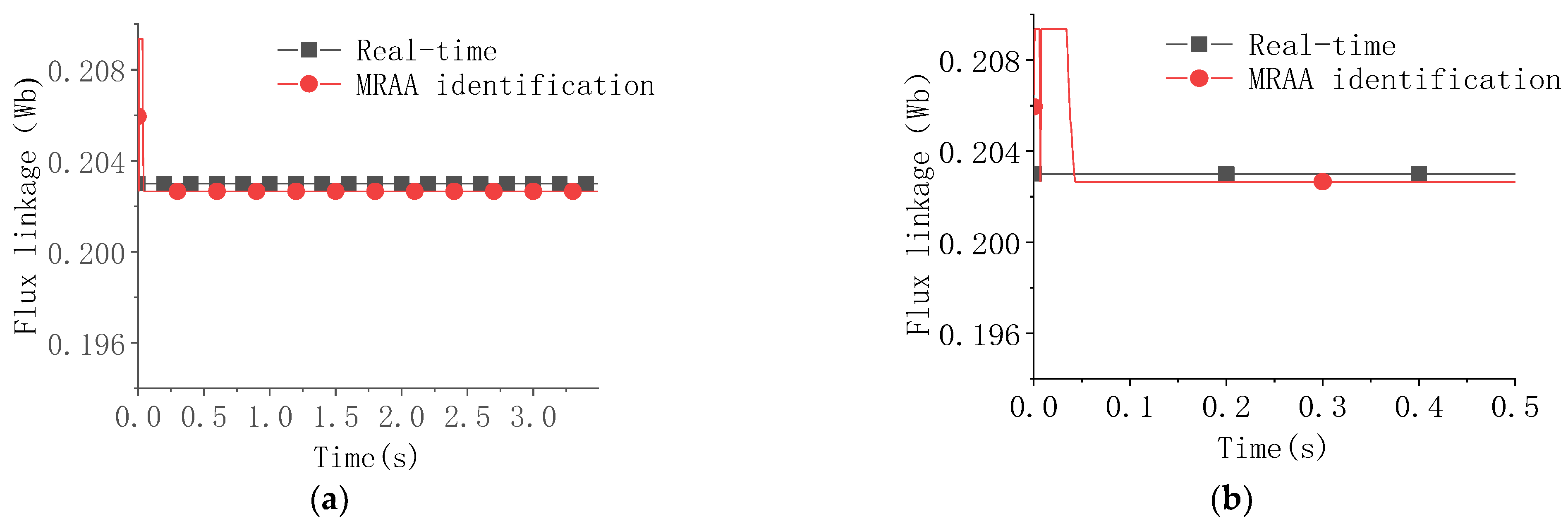
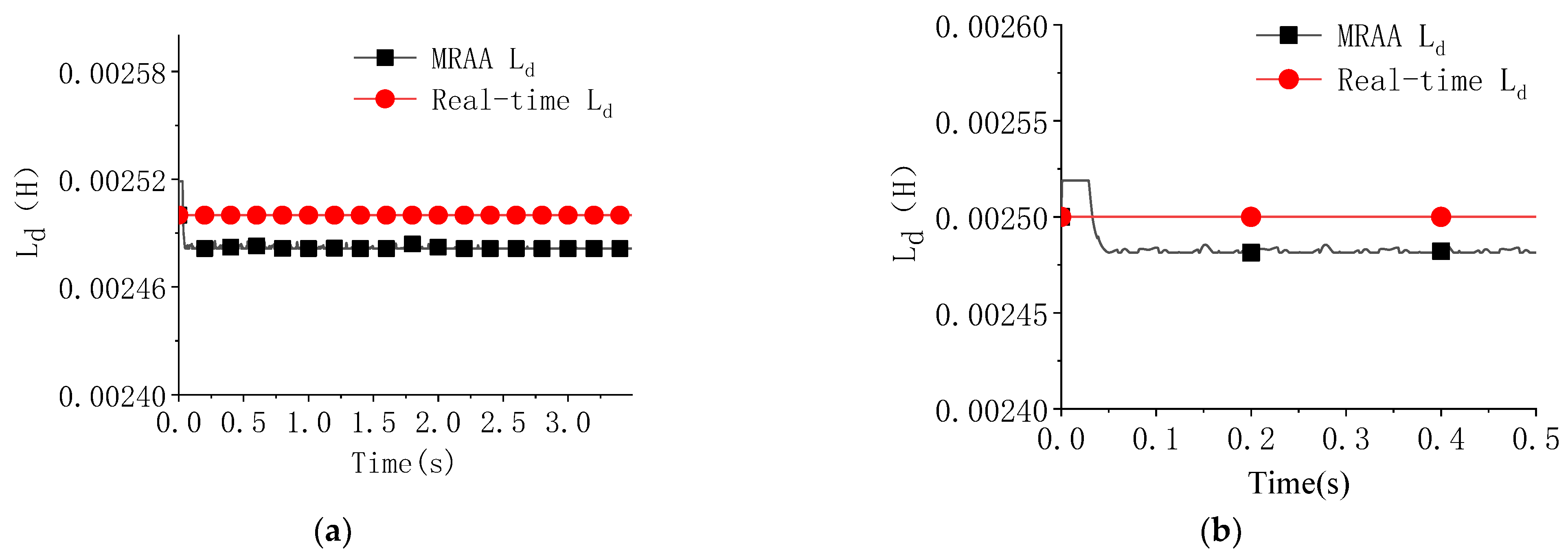
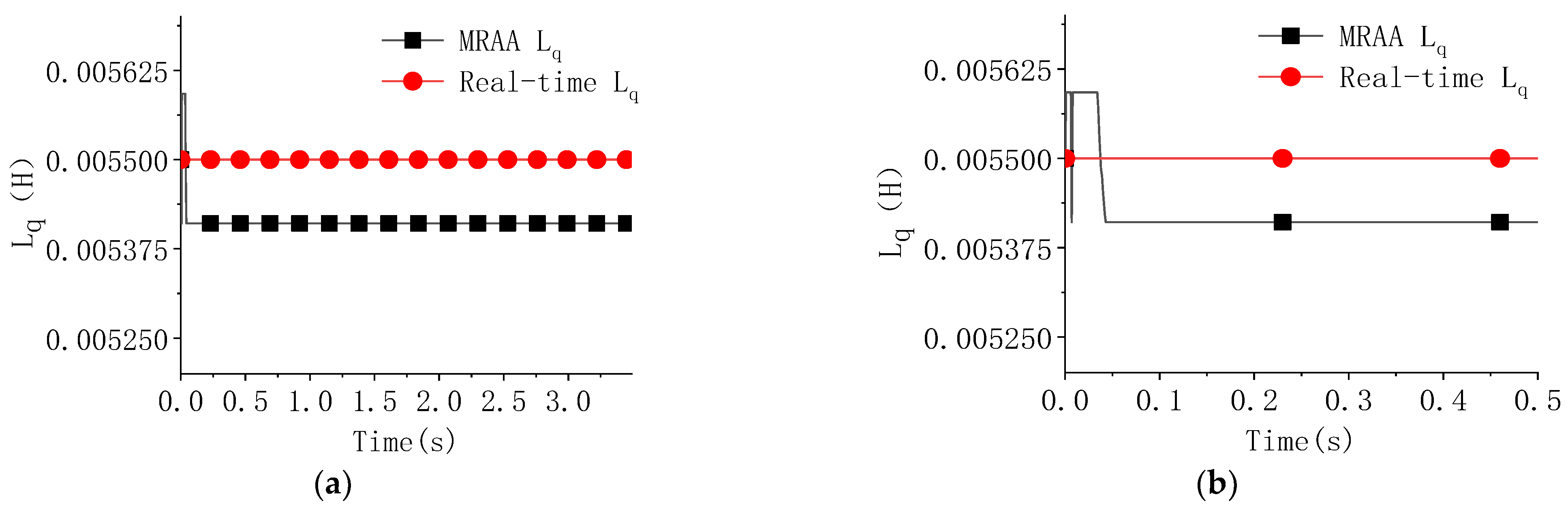
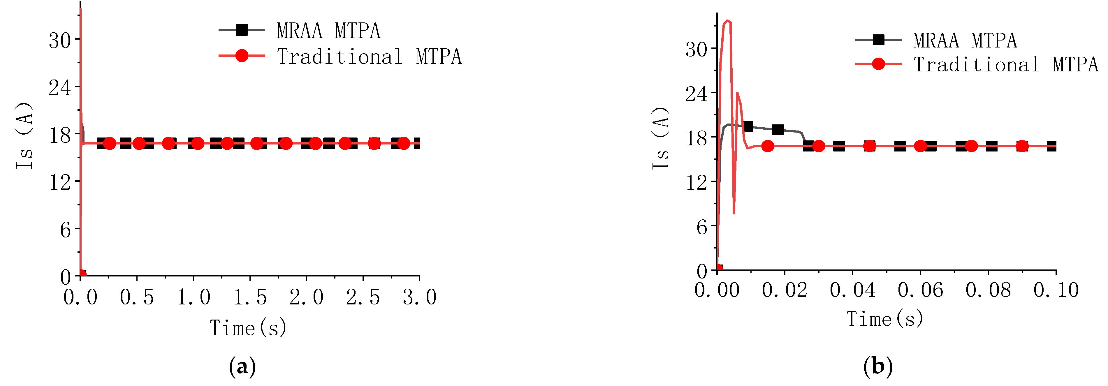
4.2. Simulation Analysis

The simulation condition settings are shown in Table 2.
The core idea of the IPMSM MRAA based on Popov hyperstability theory is to use the collected phase current and speed of the motor in the reference model to obtain the motor stator current and voltage through transformation and then input these into the adjustable model of the MRAA to obtain the observed motor stator current through mathematical equation adjustment. The adaptive rate model uses the difference of stator current between the adjustable model and the reference model to observe the parameters of the motor. Therefore, to verify the effectiveness of the method, it is necessary to check whether the stator current identification value output by the adjustable model is accurate. Table 2 lists the simulation parameters designed according to the actual working conditions of the motors listed in Table 1. The set speed of the motor is the normal low-speed working condition (not the lowest applicable working condition of the algorithm). And the maximum driving torque is the rated torque of the motor, i.e., 44 N·m. After about 3.5 s, when the model reaches the stable state, we compared the difference between the output stator current of the adjustable model and the actual stator current, as shown in Figure 9; to observe the change process of current more clearly, the curve of the anterior segment (1 s) was extracted (Figure 9b).
It can be observed that the difference between the stator winding current identification value and the actual value is almost equal to 0 after a very short time of adjustment, indicating that the identification value of the d-q axis current is consistent with the actual value, that is, the stator winding current identification value is able to gradually converge with the actual value, which proves the correctness of the simulation of the adjustable model.
The comparison results between the identified values and actual values of flux linkage, Ld and Lq, are given in Figure 10, Figure 11 and Figure 12, respectively. It can be observed that the identification results of the three parameters are able to converge with the actual value within 50 ms and the identification error is kept within 2%. The correctness of the mathematical model and simulation model of the IPMSM-MRAS parameter-identification system based on Popov hyper stability theory is verified by these results.
The speed of IPMSM based on the MRAA parameter-identification algorithm combined with MTPA control and fixed-parameter MTPA control, as well as the comparison diagram of the stator current under the same load, are given in Figure 13 and Figure 14, respectively. It can be observed that the combination of the MRAA parameter-identification algorithm with MTPA control optimizes the torque ripple of the motor at low speed, which makes the motor run more smoothly at low speed and makes the fluctuation overshoot of starting current (at low speed) more ideal, effectively suppressing the current impact under the control of the fixed-parameter MTPA.

5. Conclusions

Electric construction uses an electric motor that easily cancels the engine, which can improve efficiency and achieve zero emissions. However, the existing electric construction machinery mostly uses the motor to replace the working engine and simulate the working condition of the engine. The load is matched with the speed, torque, and power of the motor through the hydraulic torque converter, which cannot maximize the energy efficiency of the whole machine. This paper aims to understand the load direct-drive motor system of electric construction machinery, such as the direct-drive system of the loader traveling motor. The high-performance motor control method in the state of low speed and high torque is studied. Based on the vector control of the maximum torque per ampere of IPMSM, an MRAA is employed. By establishing the motor reference model and taking the motor voltage and current as the input physical quantity, the parameters of the motor model are dynamically adjusted with external interference according to the reference adaptive mathematical model, identifying the parameter values during the real-time operation of the motor. Simulation research was carried out to verify the rationality and control effect of the proposed MRAA for IPMSM. The simulation results suggest that the MRAA can identify the flux linkage and the dq-axis inductance of the motor at a low speed within 50 ms, and the parameter identification error remains below 2%. Compared with traditional MTPA control, the torque ripple of the motor controlled by the MRAA was reduced to 23.8%.
To sum up, the MRAA shows certain application potential for motor control. It can accurately identify the dynamic operating parameters of the motor so as to regulate the motor to achieve good operating performance. To further improve the availability of the algorithm, on the basis of the simulation analysis and experiments, the analysis of the impact of various interference signals on the operability of the algorithm during motor operation can be carried out in the future so as to promote its application in the field of electric construction machinery.

Author Contributions

Writing and analyzing, T.G. and Y.C.; Conceptualization and supervision, T.L.; Methodology, Q.C. and H.R.; All authors have read and agreed to the published version of the manuscript.

Funding

This research was funded by the Collaborative Innovation Platform of Fuzhou-Xiamen-Quanzhou Independent Innovation Demonstration Area (3502ZCQXT202002), the key projects of the Natural Science Foundation of Fujian Province (2021J02013), the Natural Science Foundation of Fujian Province, China (2021J01295), and the Open Foundation of the State Key Laboratory of Fluid Power and Mechatronic Systems (GZKF-202026).

Institutional Review Board Statement

Not applicable.

Informed Consent Statement

Not applicable.

Data Availability Statement

Not applicable.

Conflicts of Interest

The authors declare no conflict of interest.

References

  1. Lin, T.; Lin, Y.; Ren, H.; Chen, H.; Chen, Q.; Li, Z. Development and key technologies of pure electric construction machinery. Renew. Sustain. Energy Rev. 2020, 132, 110080. [Google Scholar] [CrossRef]
  2. Lin, T.; Chen, Q.; Ren, H.; Huang, W.; Chen, Q.; Fu, S. Review of boom potential energy regeneration technology for hydraulic construction machinery. Renew. Sustain. Energy Rev. 2017, 79, 358–371. [Google Scholar] [CrossRef]
  3. Tong, Z.-M.; Miao, J.-Z.; Li, Y.-S.; Tong, S.-G.; Zhang, Q.; Tan, G.-R. Development of electric construction machinery in China: A review of key technologies and future directions. J. Zhejiang Univ. -Sci. A 2021, 22, 245–264. [Google Scholar] [CrossRef]
  4. Zhang, S.; Minav, T.; Pietola, M.; Kauranne, H.; Kajaste, J. The effects of control methods on energy efficiency and position tracking of an electro-hydraulic excavator equipped with zonal hydraulics. Autom. Constr. 2019, 100, 129–144. [Google Scholar] [CrossRef]
  5. Liu, X.; Sun, D.; Qin, D.; Liu, J. Achievement of fuel savings in wheel loader by applying hydrodynamic mechanical power split transmissions. Energies 2017, 10, 1267. [Google Scholar] [CrossRef] [Green Version]
  6. Li, X.; Duan, C.; Bai, K.; Yao, Z. Operating Performance of Pure Electric Loaders with Different Types of Motors Based on Simulation Analysis. Energies 2021, 14, 617. [Google Scholar] [CrossRef]
  7. Li, L.; Liu, Q. Research on IPMSM drive system control technology for electric vehicle energy consumption. IEEE Access 2019, 7, 186201–186210. [Google Scholar] [CrossRef]
  8. Liu, C.; Chau, K.; Lee, C.H.; Song, Z. A critical review of advanced electric machines and control strategies for electric vehicles. Proc. IEEE 2020, 109, 1004–1028. [Google Scholar] [CrossRef]
  9. Pomponi, C.; Scalzi, S.; Pasquale, L.; Verrelli, C.; Marino, R. Automatic motor speed reference generators for cruise and lateral control of electric vehicles with in-wheel motors. Control Eng. Pract. 2018, 79, 126–143. [Google Scholar] [CrossRef]
  10. Hu, J.; Jia, M.; Xiao, F.; Fu, C.; Zheng, L. Motor vector control based on speed-torque-current map. Appl. Sci. 2019, 10, 78. [Google Scholar] [CrossRef] [Green Version]
  11. Guo, T.; Cai, S.-L.; Chen, Q.-H.; Lin, T.-L.; Chen, H.-B.; Fu, S.-J.; Guo, H.-B. Electro-hydraulic Shift System and Control Strategy for Pure Electric Loader Based on Pressure Feedback. Chin. Hydraul. Pneum. 2020, 0, 22–29. [Google Scholar] [CrossRef]
  12. Djeriou, A.; Houari, A.; Machmoum, M.; Mesbahi, T.; Ghanes, M. Cascade GW Controllers for Speed Ripple Minimization at Low Speed Operation of PMSM Drives for EV. In Proceedings of the IECON 2020 the 46th Annual Conference of the IEEE Industrial Electronics Society, Singapore, 18–21 October 2020; pp. 4667–4672. [Google Scholar]
  13. Djeriou, A.; Drihem, D. On the Continuity of Pseudo-Differential Operators on Multiplier Spaces Associated to Herz-type Triebel–Lizorkin Spaces. Mediterr. J. Math. 2019, 16, 1–25. [Google Scholar] [CrossRef]
  14. Elsonbaty, N.A.; Enany, M.A.; Hassanin, M.I. An Efficient Vector Control Policy for EV-Hybrid Excited Permanent-Magnet Synchronous Motor. World Electr. Veh. J. 2020, 11, 42. [Google Scholar] [CrossRef]
  15. Ahmed, M.M.; Hassanein, W.S.; Elsonbaty, N.A.; Enany, M.A. Proposing and evaluation of MPPT algorithms for high-performance stabilized WIND turbine driven DFIG. Alex. Eng. J. 2020, 59, 5135–5146. [Google Scholar] [CrossRef]
  16. Zhu, L.; Xu, B.; Zhu, H. Interior Permanent Magnet Synchronous Motor Dead-Time Compensation Combined with Extended Kalman and Neural Network Bandpass Filter. Prog. Electromagn. Res. M 2020, 98, 193–203. [Google Scholar] [CrossRef]
  17. Fu, S.; Ren, H.; Lin, T.; Zhou, S.; Chen, Q.; Li, Z. SM-PI control strategy of electric motor-pump for pure electric construction machinery. IEEE Access 2020, 8, 100241–100250. [Google Scholar] [CrossRef]
  18. Bobtsov, A.; Pyrkin, A.; Aranovskiy, S.; Nikolaev, N.; Slita, O.; Kozachek, O.; Quoc, D.V. Stator flux and load torque observers for PMSM. IFAC-Pap. 2020, 53, 5051–5056. [Google Scholar] [CrossRef]
  19. Pyrkin, A.; Bobtsov, A.; Ortega, R.; Vedyakov, A.; Cherginets, D.; Bazylev, D.; Igor, P. Sensorless control of permanent magnet synchronous motors based on finite-time robust flux observer. IFAC-Pap. 2020, 53, 9270–9275. [Google Scholar] [CrossRef]
  20. Bobtsov, A.; Nikolaev, N.; Pyrkin, A.; Slita, O.; Titova, E. Simple speed observer for PMSM. In Proceedings of the 2017 9th International Congress on Ultra Modern Telecommunications and Control Systems and Workshops (ICUMT), Munich, Germany, 6–8 November 2017; pp. 324–328. [Google Scholar]
  21. Bazylev, D.; Pyrkin, A.; Bobtsov, A. Position and speed observer for PMSM with unknown stator resistance. In Proceedings of the 2018 European Control Conference (ECC), Limassol, Cyprus, 12–15 June 2018; pp. 1613–1618. [Google Scholar]
  22. Choi, K.; Kim, Y.; Kim, K.-S.; Kim, S.-K. Using the stator current ripple model for real-time estimation of full parameters of a permanent magnet synchronous motor. IEEE Access 2019, 7, 33369–33379. [Google Scholar] [CrossRef]
  23. Kim, Y.; Seo, H.-T.; Kim, S.-K.; Kim, K.-S. A robust current controller for uncertain permanent magnet synchronous motors with a performance recovery property for electric power steering applications. Energies 2018, 11, 1224. [Google Scholar] [CrossRef] [Green Version]
  24. Choi, K.; Kim, Y.; Kim, K.-S.; Kim, S.-K. Real-time optimal torque control of interior permanent magnet synchronous motors based on a numerical optimization technique. IEEE Trans. Control Syst. Technol. 2020, 29, 1815–1822. [Google Scholar] [CrossRef]
  25. Kim, Y.; Kim, S.-K.; Ahn, C.K. Variable-performance proportional-type angle-filtering system for motor drives. IEEE Trans. Circuits Syst. II Express Briefs 2020, 68, 511–515. [Google Scholar] [CrossRef]
  26. Gai, H.; Li, X.; Jiao, F.; Cheng, X.; Yang, X.; Zheng, G. Application of a New Model Reference Adaptive Control Based on PID Control in CNC Machine Tools. Machines 2021, 9, 274. [Google Scholar] [CrossRef]
  27. Zaky, M.S.; Khater, M.M.; Shokralla, S.S.; Yasin, H.A. Wide-speed-range estimation with online parameter identification schemes of sensorless induction motor drives. IEEE Trans. Ind. Electron. 2008, 56, 1699–1707. [Google Scholar] [CrossRef]
  28. Gatto, G.; Marongiu, I.; Serpi, A. Discrete-time parameter identification of a surface-mounted permanent magnet synchronous machine. IEEE Trans. Ind. Electron. 2012, 60, 4869–4880. [Google Scholar] [CrossRef]
Figure 1. Structural block diagram of the MRAA.
Machines 10 00575 g001
Figure 2. Structural block diagram of Popov hyper stability theory.
Machines 10 00575 g002
Figure 3. Block diagram of the adaptive rate system.
Machines 10 00575 g003
Figure 4. Block diagram of adaptive rate system.
Machines 10 00575 g004
Figure 5. MRAA reference model.
Machines 10 00575 g005
Figure 6. MRAA adjustable model.
Machines 10 00575 g006
Figure 7. MRAA adaptive rate model.
Machines 10 00575 g007
Figure 8. Simulation model of IPMSM MRAA based on Popov hyper stability theory.
Machines 10 00575 g008
Figure 9. Difference between the stator current identification value and the actual value. (a) Stator current identification difference and (b) the local magnification of the anterior segment.
Machines 10 00575 g009
Figure 10. Comparison between the MRAA-identified flux linkage and actual flux linkage. (a) Comparison of flux linkage and (b) the local magnification of the anterior segment.
Machines 10 00575 g010
Figure 11. Comparison between the MRAA-identified Ld and the actual Ld. (a) Comparison of Ld and (b) the local magnification of the anterior segment.
Machines 10 00575 g011
Figure 12. Comparison between the MRAA-identified Lq and the actual Lq. (a) Comparison of Lq and (b) the local magnification of the anterior segment.
Machines 10 00575 g012
Figure 13. Speed comparison between MRAA-MTPA control and fixed-parameter MTPA control. (a) Comparison of speed and (b) the local magnification of the anterior segment.
Machines 10 00575 g013
Figure 14. Comparison between MRAA-MTPA control and fixed-parameter MTPA control. (a) Comparison of stator current and (b) the local magnification of the starting segment.
Machines 10 00575 g014
Table 1. Parameters of IPMSM.
Rated Torque (N·m)Rated Speed (r/min)Rated Power (kW)Ld (mH)Lq (mH)Stator Resistance (Ω)Moment of Inertia (kg·m2)Pole Pair
44180092.55.50.170.00552
Table 2. Simulation conditions.
Target SpeedTarget TorqueLdLqFlux Linkage
120 r/min14 N·m2.5 mH5.5 mH0.203 Wb
Publisher’s Note: MDPI stays neutral with regard to jurisdictional claims in published maps and institutional affiliations.

