Communication

New Mechanical Knee Supporter Device for Shock Absorption

by
Hajime Shiraishi
1 and
Haruhiro Shiraishi
2,*
1
Department of Mechanical Systems Engineering, Kurume Institute of Technology, Fukuoka 830-0052, Japan
2
Graduate School of Frontier Sciences, The University of Tokyo, Chiba 277-8561, Japan
*
Author to whom correspondence should be addressed.
Machines 2022, 10(7), 574; https://doi.org/10.3390/machines10070574
Submission received: 24 June 2022 / Revised: 13 July 2022 / Accepted: 15 July 2022 / Published: 16 July 2022
(This article belongs to the Section Machine Design and Theory)

Abstract

:
Conventional knee supporters generally reduce knee pain by restricting joint movement. In other words, there were no mechanical knee supporters that functioned powerfully. Considering this problem, we first devised a device in which a spring is inserted into the double structure of the cylinder and piston, and a braking action is applied to the piston. This mechanism retracts when the knee angle exceeds a certain level. Next, the knee and the device were modeled, and the dynamic characteristics of the device were investigated to find effective elements for knee shock absorption. Although various skeletal and muscular structures have been studied for the knee section, we kept the configuration as simple as possible to find effective elements for the device. A shock-absorbing circuit was devised, and air was used as the working fluid to facilitate smooth knee motion except during shock. Increasing the spring constant effectively reduced the knee load.

1. Introduction

Conventional knee supporters were generally made of elastic cloth or taping tape imitations that were worn on the knee to restrict joint movement and reduce knee pain [1,2,3,4,5]. Others inserted nylon rods in the direction of the bone axis or added a spring function to the rear of the knee, but there were no mechanical knee supporters that functioned as powerfully as a bicycle suspension. For example, dampers used in automobiles, motorcycles, and other vehicles use hydraulic pressure, but those directly applied to the body structure do not exist as far as the author has been able to determine. In addition, the use of oil had the disadvantages of being easily contaminated and difficult to remove small impacts due to the difficulty of compression. Considering these problems, the authors decided to develop a device using air pressure that can absorb knee shocks more powerfully than conventional devices during normal exercise such as walking, stair climbing, mountain climbing, and jogging. A below-the-knee body model of such a simple knee supporter has already been proposed in the fields of agriculture and nursing care by Shiraishi et al. It was not sufficient to develop a new simplified supporter device based on this model. In addition, only a basic model was developed, and it was considered insufficient as a practical product in light of the actual human body model [6]. It was also thought that if this product could be provided safely and inexpensively, it would be useful not only in the fields of agriculture and nursing care, but also in preventing knee failures during light exercise in middle-aged and older people, etc., and could also be applied to lifelong sports, etc. [7,8].
This knee supporter is not an advanced power-assist device that has been widely researched and developed [9,10,11,12]. The reason for not utilizing a power-assist device was that there existed inadequacies as a device, such as too much load on the body and discomfort, because it forces a forced force against the body structure. In addition, there were disadvantages such as the time required to wear the device, the difficulty of using it simply, and the need to wear a device with a different function for each movement. Therefore, we developed a mechanical knee supporter that is as inexpensive as possible, has a simple structure, and can handle high-speed movements, replacing conventional fabric knee supporters and power-assist devices. Humans can effectively reduce walking impact by flexing the knee after a blow [13,14,15]. Furthermore, the stiffness and damping of the human leg are crucial to reduce joint and limb damage during impact [16,17]. This knee supporter can be easily applied because it is secured with a belt, making it a machine that does not place a load on the body structure. In addition, since the individual functions work according to each movement, there exists the advantage of eliminating the trouble of wearing different devices. Because the device is small, it can be worn without discomfort. Since it is operated not by an actuator such as a motor, but only by a solenoid valve and a piezoelectric element, it consumes little electricity. The basic structure consists of only dampers and springs, which are activated as needed by signals from sensors. In addition, the mechanism allows the knee to be bent to a large extent (~180°). In addition, conventional springs can reduce displacement, but cannot absorb shock. In this study, we attempted to improve these problems by combining a spring and a damper. In addition, shock-absorbing soles have existed to absorb shock at the ankle, but it is difficult to adapt them to different shocks. In addition, supporters that restrict movement, such as cloth supporters, have existed in the past, but there was no such supporter that also functioned to absorb shock. Thus, we clarified the problems in the configuration of conventional device elements and attempted to develop a completely new device that solves these problems.

2. Concept

The concept is to develop a device that can absorb knee shocks more powerfully than conventional ones when walking, climbing stairs, mountain climbing, jogging, etc. A simple knee supporter device as shown in Figure 1.

3. Development Objectives

The following four goals were set for the development of this product.
(1)
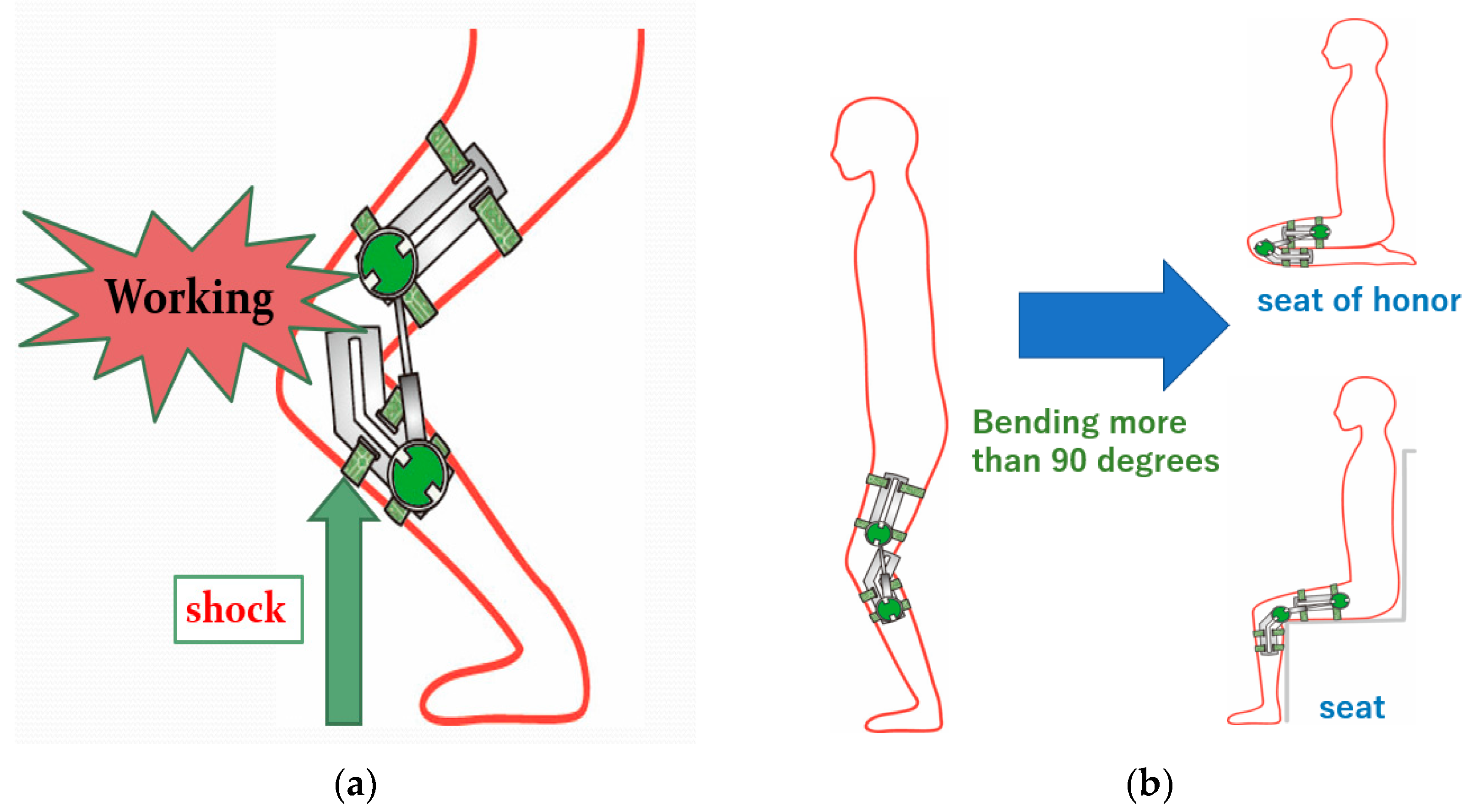
This product will be activated only when a shock is applied during knee bending, such as when ascending or descending stairs or running. The product does not operate during normal, slow bending of the lower limb. Since the product also does not operate when the knee is extended, stretching exercises can be performed without discomfort. (Figure 2a).
(2)
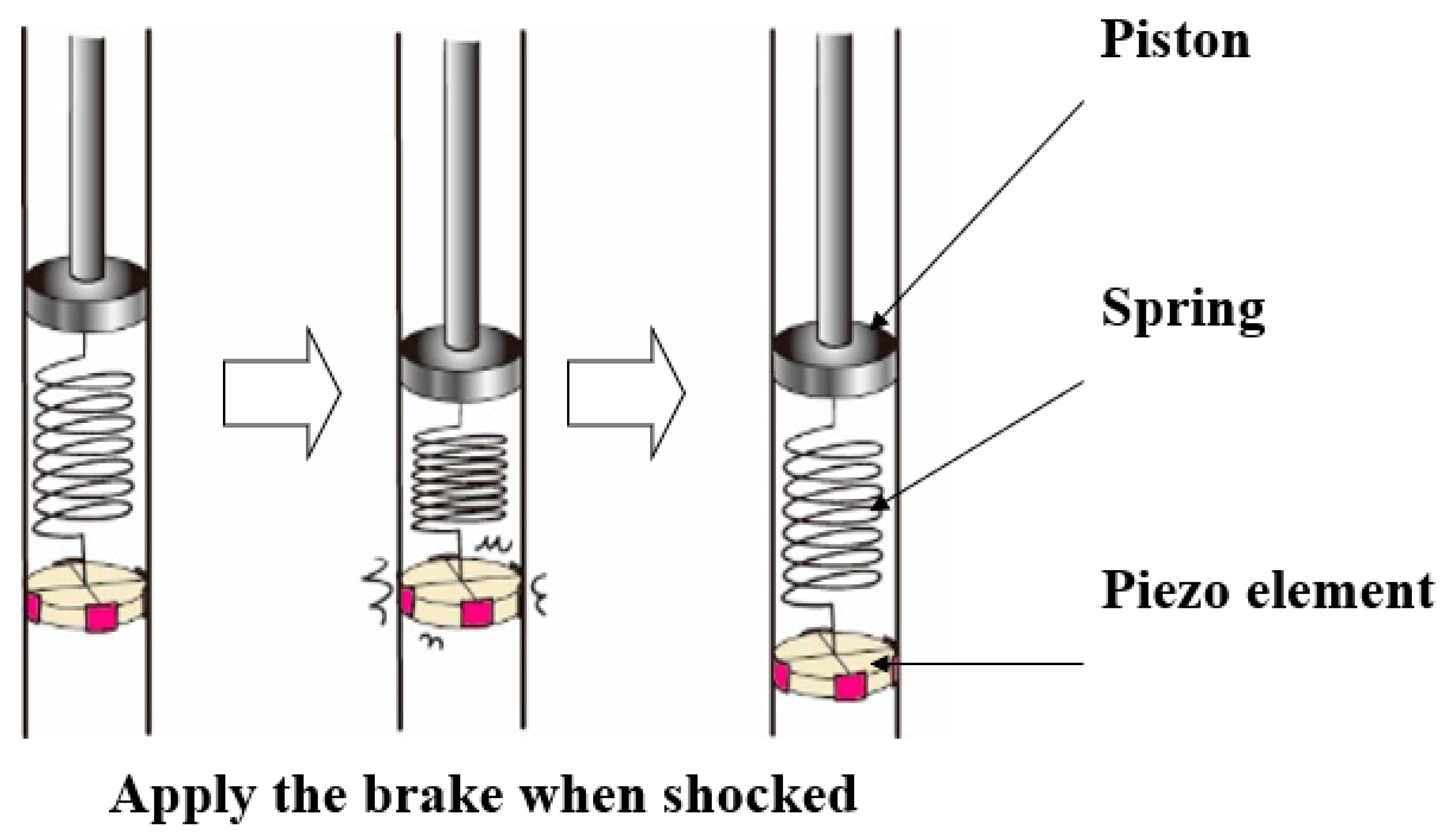
As a mechanism to absorb sudden load applied to the knee, a spring shall be used for the first large load, and air pressure shall be used for the subsequent loads.
(3)
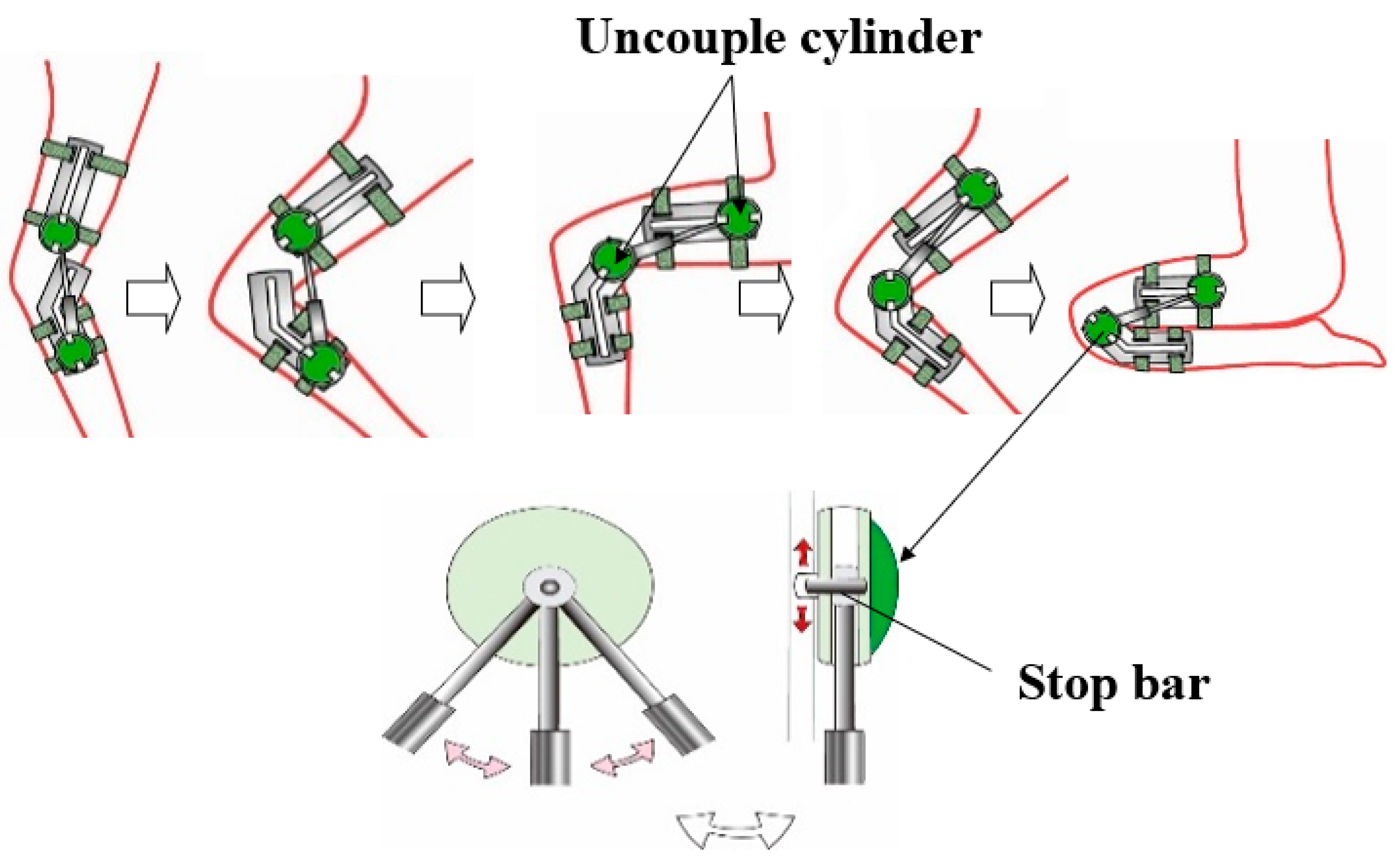
When the knee is bent more than 90°, the product is retracted, and the user can sit upright. (Figure 2b).
(4)
The actuator is operated only for a short period of time compared to those that use a motor all the time, consumes less electricity, and can be operated by a small battery.

4. Shock Mitigation and Absorption Mechanism

The device is shown in Figure 3, with the knee shock and relaxation absorption performed by the cylinder system, pneumatic circuit, and control uni.
Shock and relaxation absorption of the knee was performed by the cylinder system, pneumatic circuit, and control unit. The device is shown mounted in Figure 3. As shown in Figure 3, the knee can be bent at various angles, eliminating the need for mounting each time. The device can be quickly attached and used for various purposes. The bending is also soft and can absorb even small shocks.

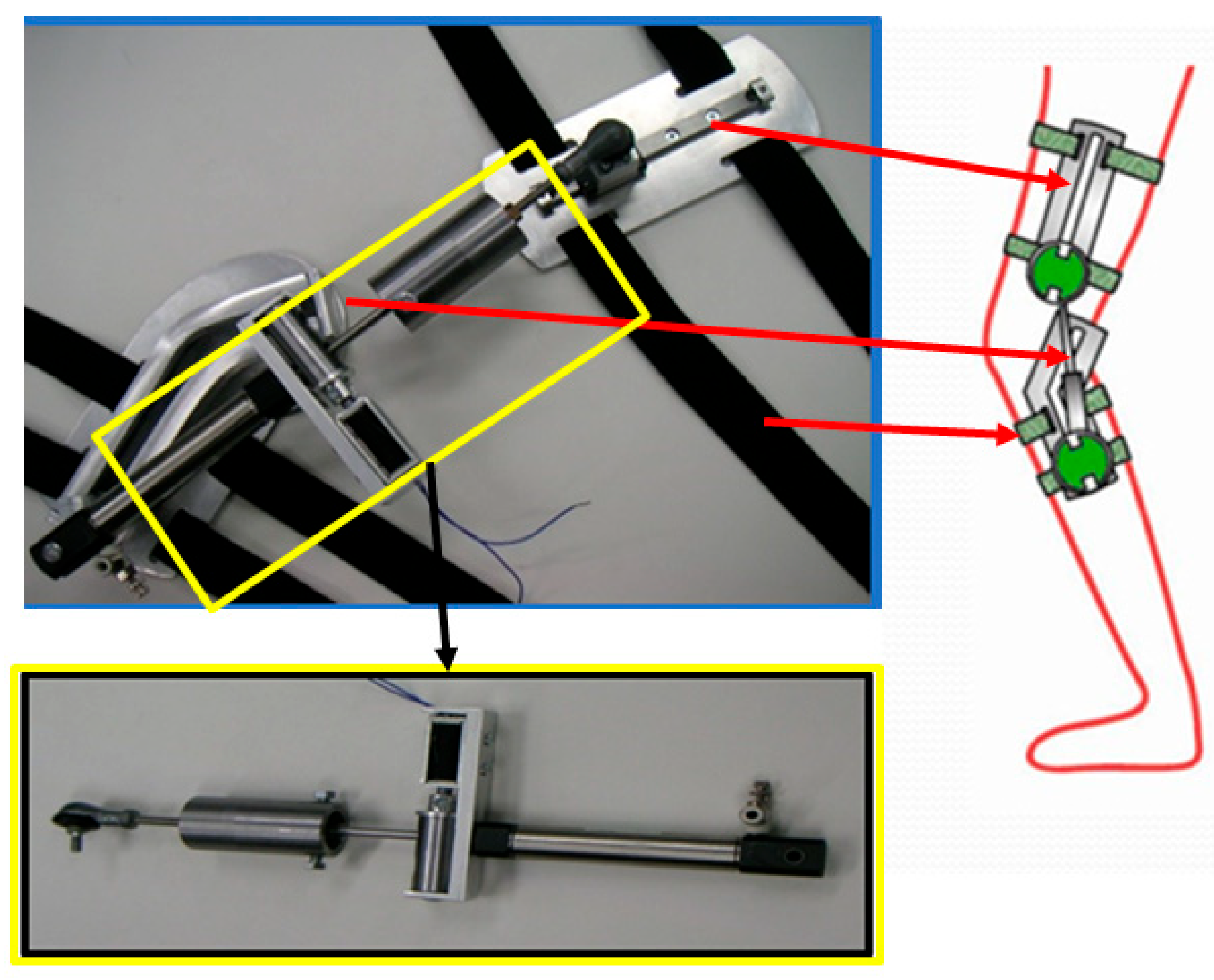
4.1. Cylinder System for Shocks

As shown in Figure 4, the cylinder piston section of the newly devised system is double, with a spring inserted between them. A piezoelectric element is attached to the piston section on the opposite side of the cylinder rod, and when the piezoelectric element is activated, a braking action is applied to the piston. At that point, the spring force acts when the rod is pushed down. The piezo element moves because it moves in unison with the piston. The spring also functions to reduce displacement.
When the piezoelectric element does not work, the piston and spring move in unison and function in the same manner as a normal cylinder. Piezoelectric elements have the advantage of high response and large force per volume, but the voltage-displacement ratio is small. In this case, the displacement was 40 μm at 140 VDC.

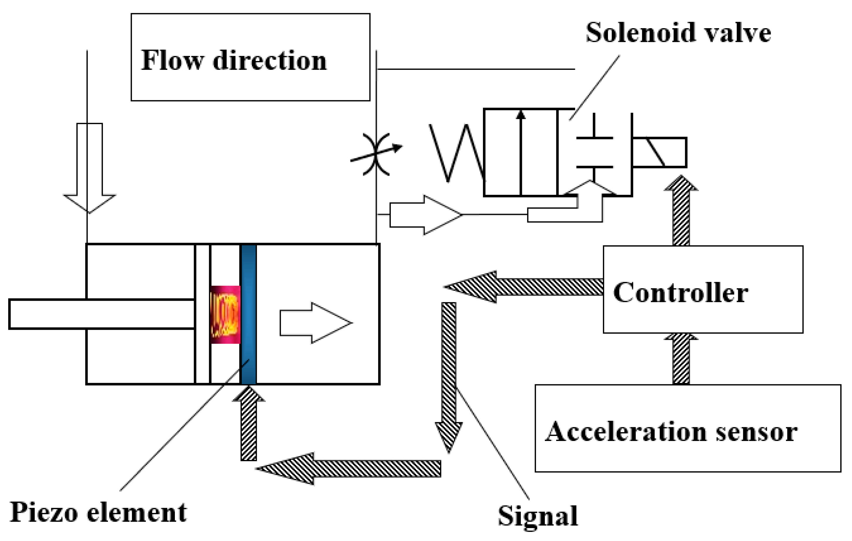
4.2. Pneumatic Circuit

When an acceleration sensor attached to the sole detects a shock, the piezoelectric element and pneumatic valve are activated. The power supply is 24 V for the valve, which can be substituted for a smartphone battery. The piezoelectric element requires voltage, but only for 0.2–0.3 s, so power consumption can be kept very low. The cylinder (damper) contains a spring and a piezoelectric element. A pneumatic circuit was devised that not only moves the cylinder independently, but also activates it only in the event of a shock. This circuit reduces the resistance to actuate the cylinder except when a shock is applied. Figure 5 shows the circuit when no shock is applied. The air flowing into and out of the cylinder passes through the open circuit of the solenoid switching valve without passing through the throttle valve, allowing the cylinder rod to move smoothly. If oil is used as the cylinder’s working fluid, the cylinder resistance during normal operation (when no shocks are applied) increases.
Figure 6 shows the circuit when a shock is applied. First, when the acceleration sensor detects a shock, the piezoelectric element is activated to fix the piston in the cylinder for a certain period of time. The initial large shock is absorbed by the spring. At the same time, the solenoid valve is closed. Subsequently, the piezoelectric element is disengaged, and the cylinder rod is lowered, leaving no place for air to escape from the head side, and the shock is softly received by the air compressibility.

5. Simulation of Cylinder System

The effect of the cylinder system was confirmed by simulation. Figure 7 shows the cylinder rod displacement–time and acceleration–time relationships for the air compressibility only, and Figure 8 shows the spring. Figure 9 and Figure 10 for the combined spring and cylinder system. As a pseudo-shock, a step-like 14 × 9.8 N input was applied between 0.5–0.6 s.
As shown in Figure 7, the method using only the compressibility of air results in a gradual displacement of the rod, but the displacement is only about 0.25 m, making it difficult to make the total cylinder length practical. The use of oil as the working fluid could be considered here, but oil would increase the operating resistance during non-operation. In addition, as shown in Figure 8, when only a spring is used, the acceleration changes significantly, indicating that the shock is not effectively absorbed. The use of oil as the working fluid could be considered here, but oil would increase the operating resistance when the system is not in operation. Observing the combined spring and pneumatic compressibility in Figure 9 and Figure 10, it is possible to vary the shock more gently than with the spring alone at practical cylinder displacements. Figure 9 shows the piezoelectric element with an operating time of 0.5 s to 0.6 s, and Figure 10 shows the same with an operating time of 0.5 s to 0.55 s, but it can be observed that the displacement and acceleration of the rod are significantly different.

6. Cylinder Slide Mechanism

When this product is installed, sitting, bending, and other movements are restricted due to the cylinder length. Therefore, when the knees are bent significantly, the cylinder is slid to enable sitting upright. Figure 11 shows an overview of this structure. First, a position sensor detects that the knee has been bent significantly. At the same time, the bar restraining the cylinder to the rail is released, and the cylinder moves upward along the rail. Figure 12 shows the prototype developed for this project.

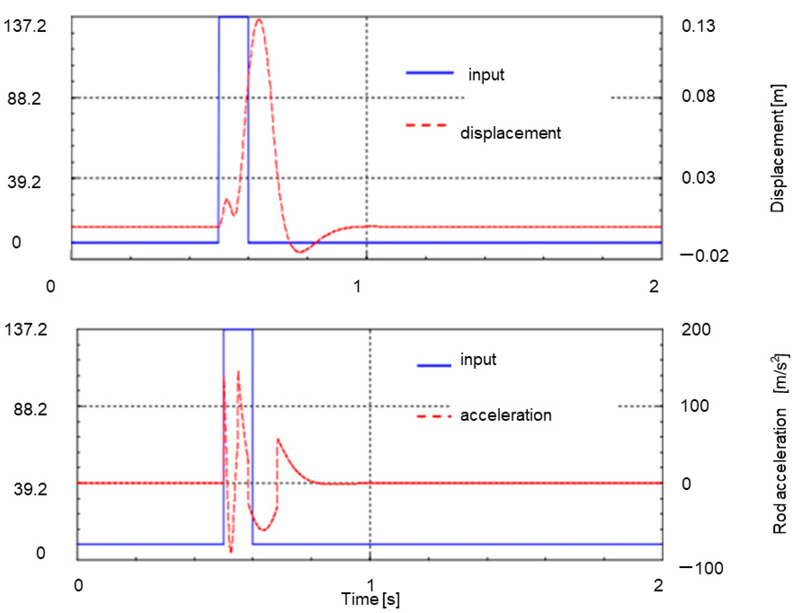
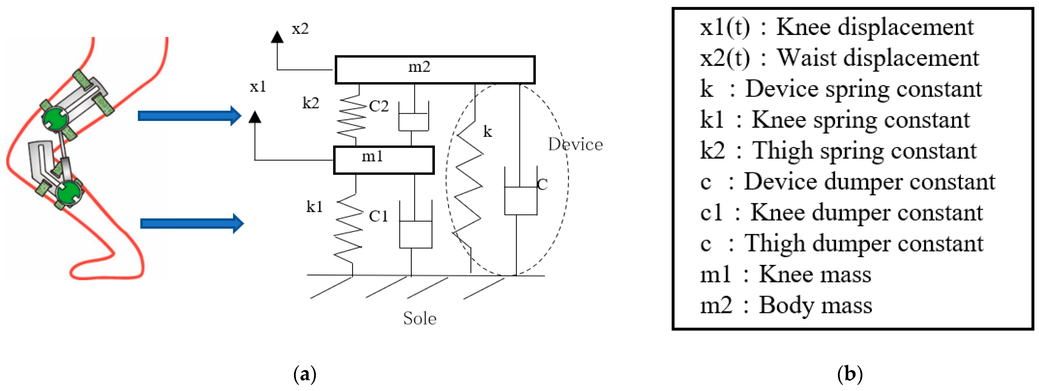
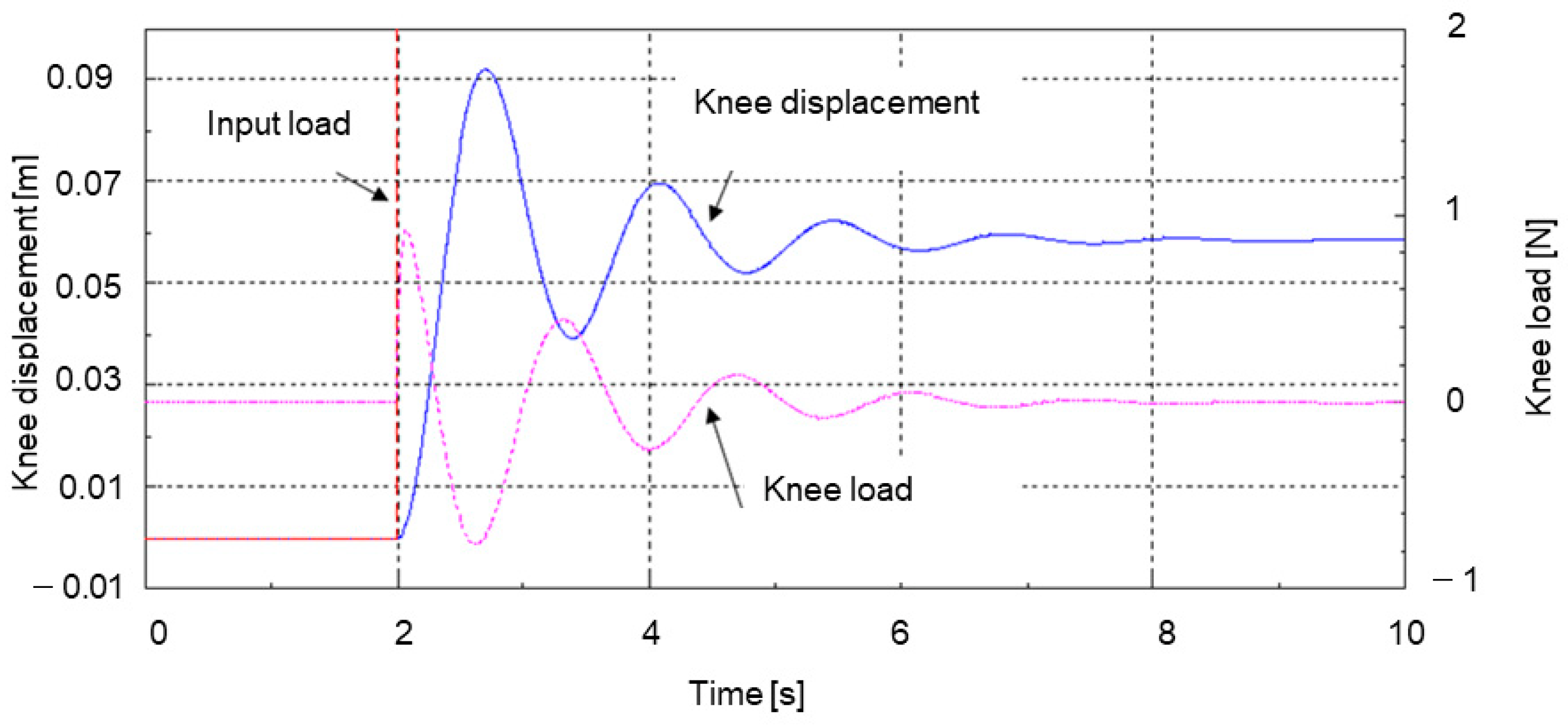
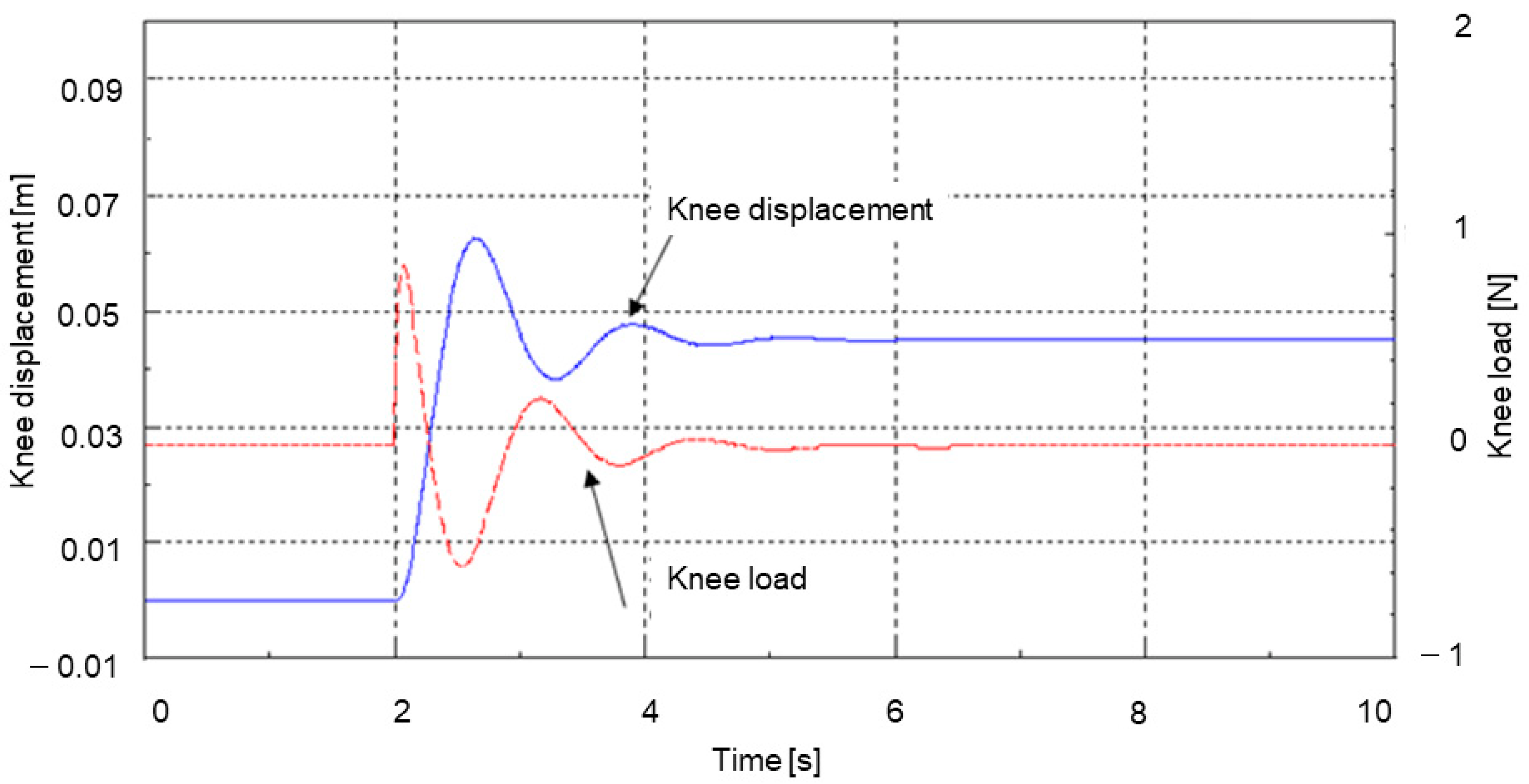
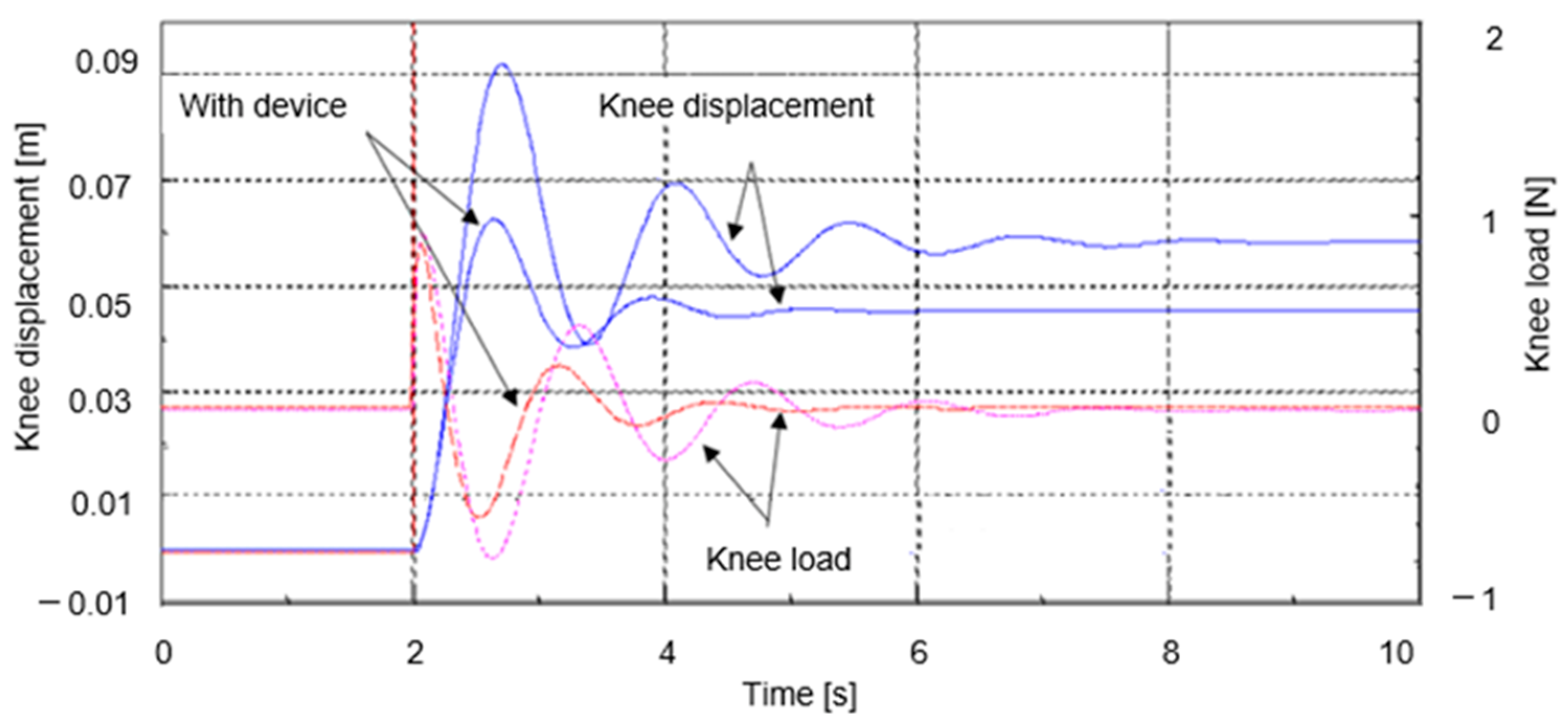
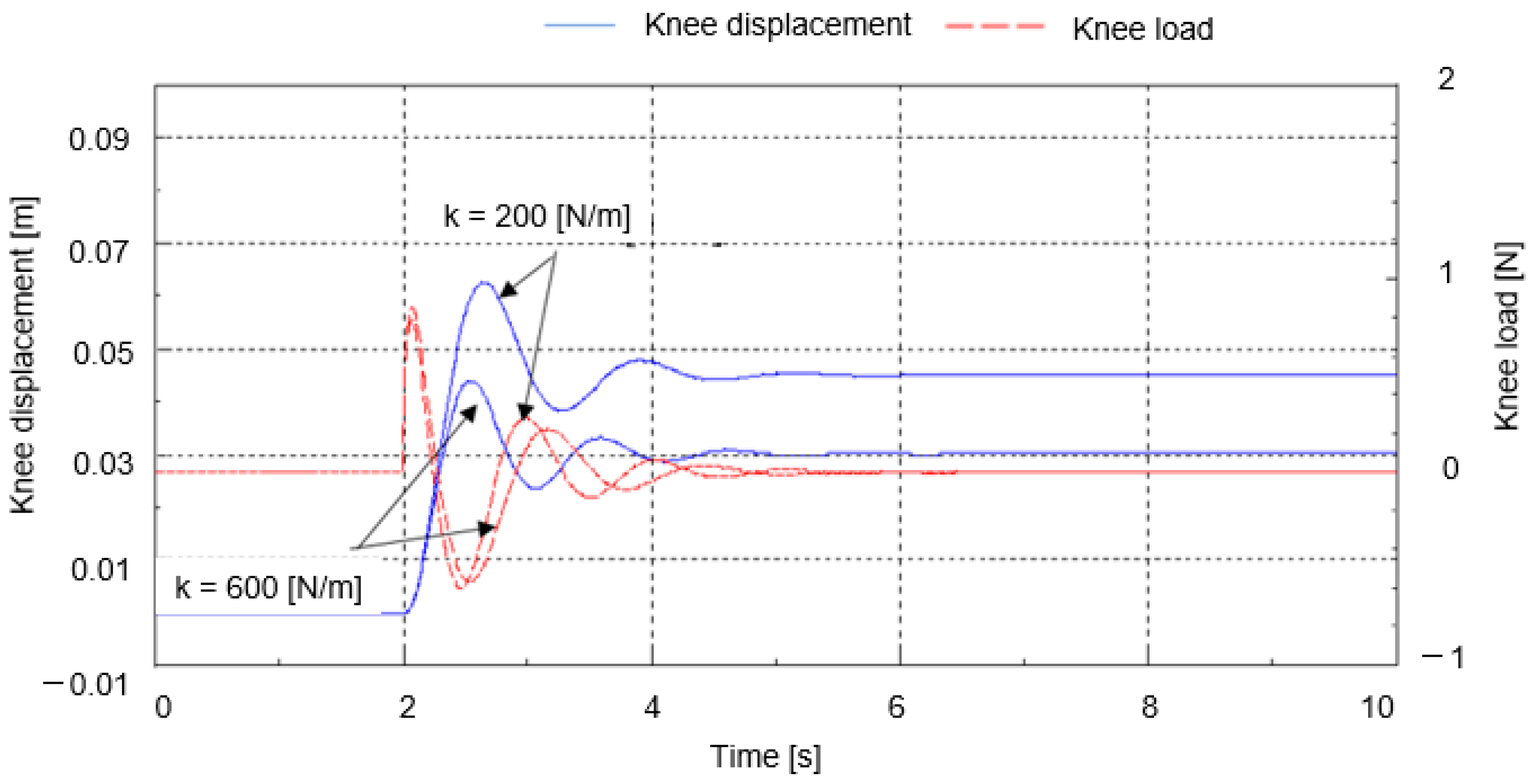
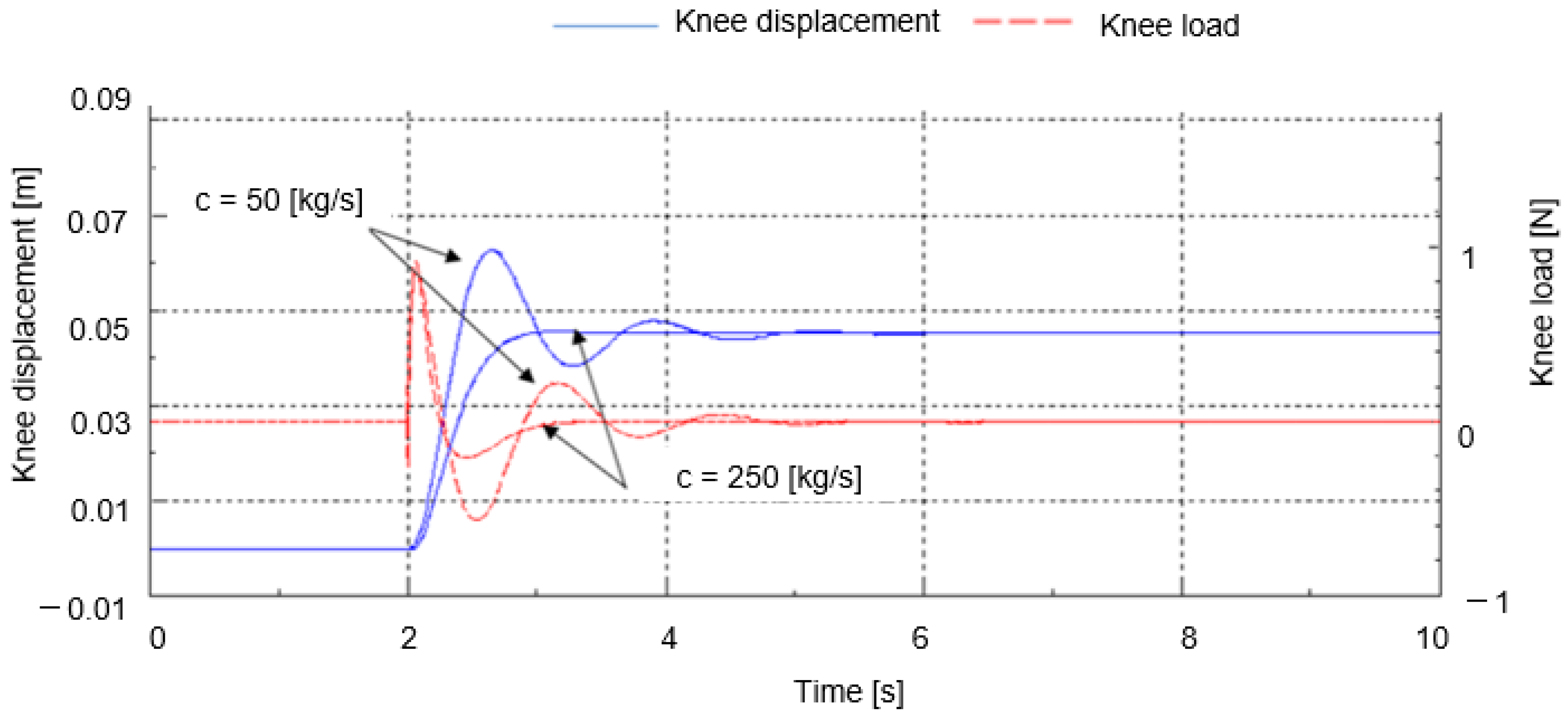
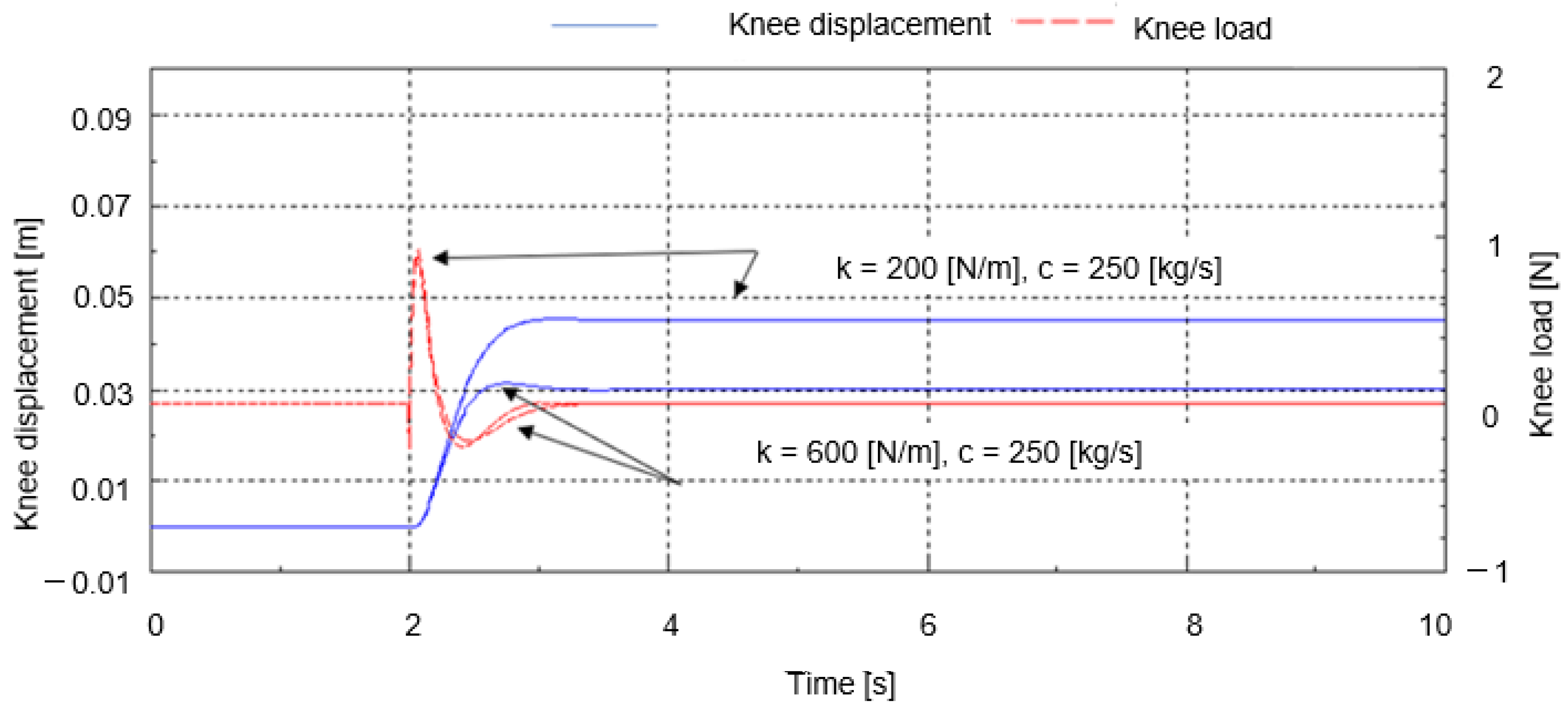
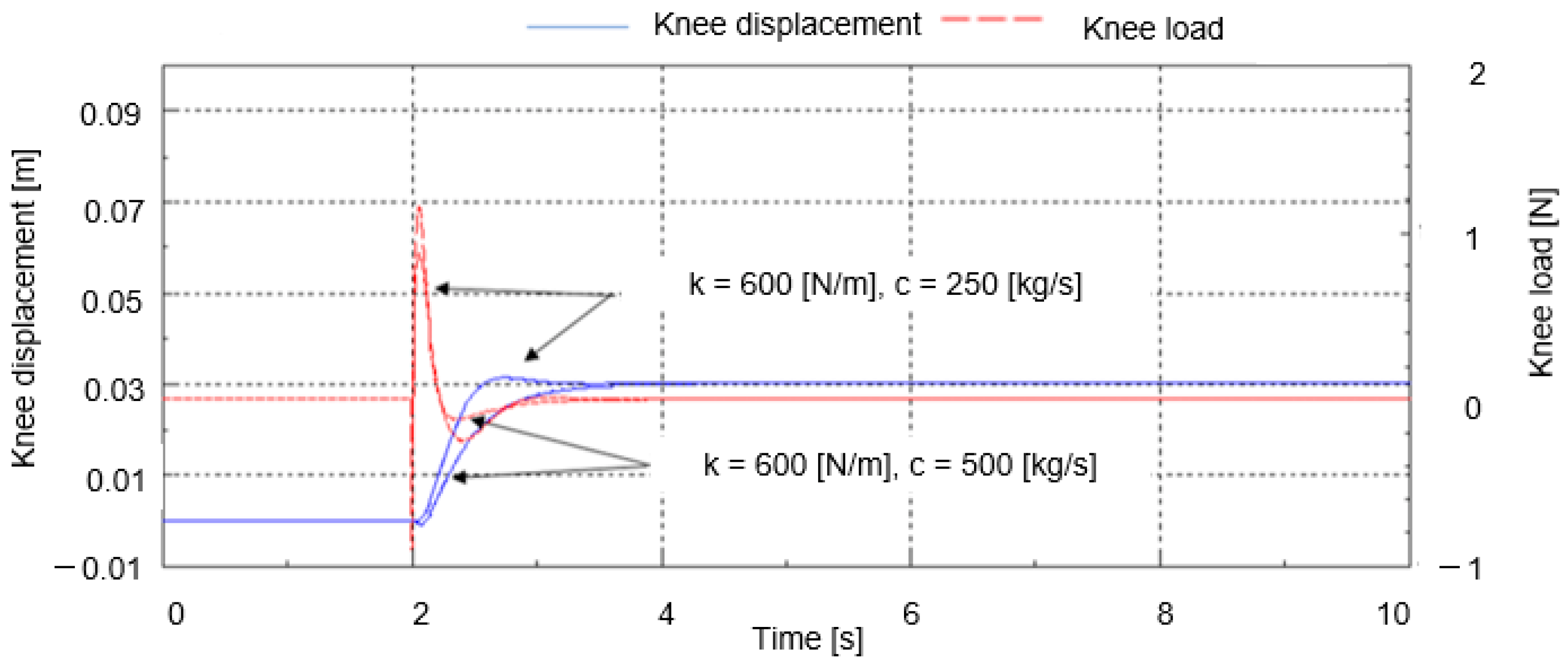
7. Analysis of Dynamic Characteristics of the Device

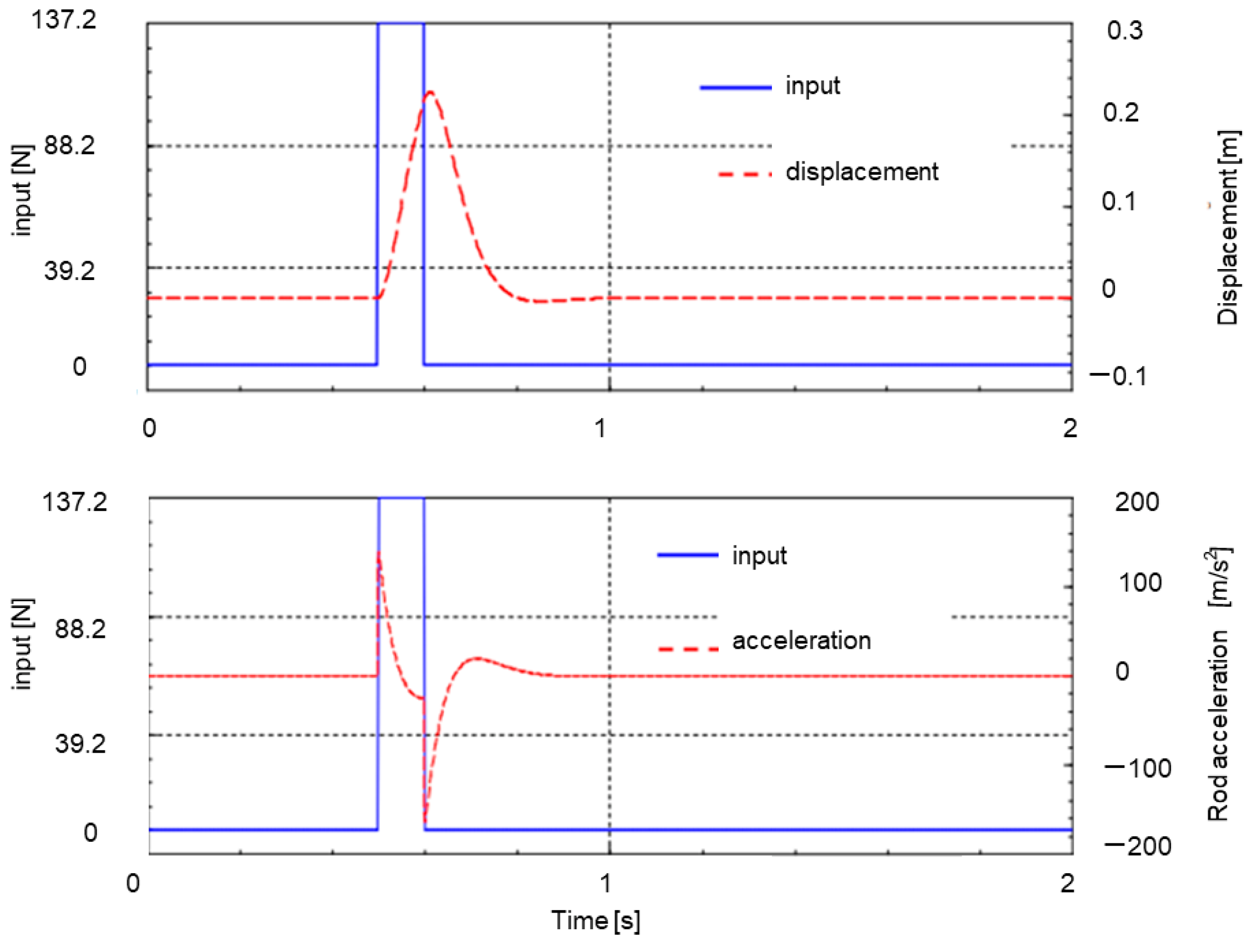
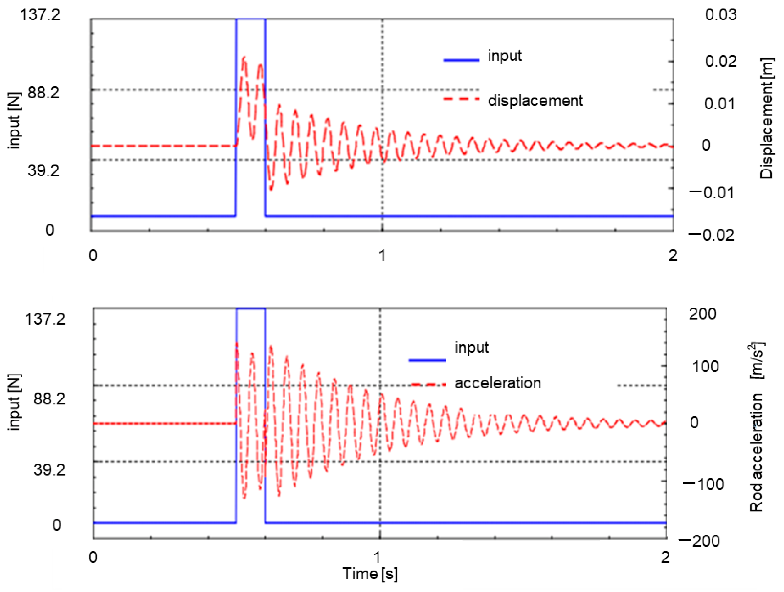
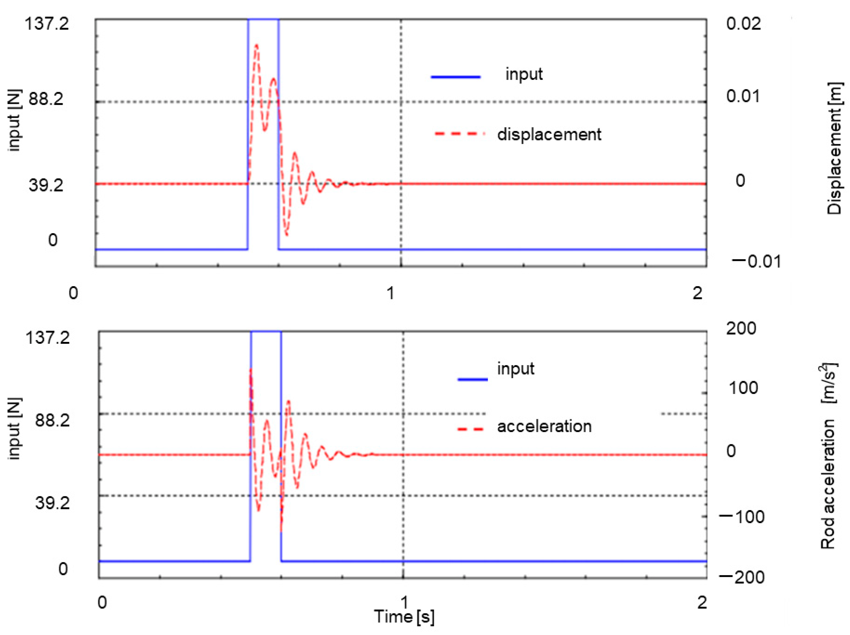
Calculation Results of the Model in the Dynamic Analysis of the Device

To investigate the dynamic characteristics of the device and find effective elements for knee shock absorption, the knee portion and the device were modeled. The knee area is composed of various skeletal and muscular structures that have been studied, but to find effective elements for the device, we kept the configuration as simple as possible. The knees are shown in an upright position. The device contains springs and dampers in series, but in the model, they are inserted in parallel, as is common. This is also to make it easier to understand the characteristics of the elements of the device.
As shown in Figure 13, the spring constant and damper coefficient of the thigh section are represented by k2 and c2, and those of the knee section by k1 and c1. The spring constant and damper coefficient of the apparatus are represented by k and c. The equation of motion without the device is a two-degree-of-freedom system and can be expressed as (1) and (2), where F(t) is the external force. Equations (3) and (4) are also obtained by including the device.
m 2   x 2 ¨ =   F t   k 2 x 2   x 1   c 2 ( x 2 ˙ x 1 ) ˙
m 1   x 1 ¨ =   c 2 ( x 1 ˙   x 2 ) k 2 ( x 1 ˙ x 2 )   k 1 x 1   c 1   x 1 ˙
m 2   x 2 ¨ =   F t   k 2 x 2   x 1   c 2 ( x 2 ˙ x 1 )   kx 2   c x 2 ˙ ˙
m 1   x 1 ¨ =   c 2 ( x 1 ˙   x 2 ) k 2 ( x 1 ˙ x 2 )   k 1 x 1   c 1   x 1 ˙   kx 2   c x 2   ˙
Based on the model equations, the effects of the spring constant and damper coefficient on the knee were investigated. Figure 14 shows the basic results. Figure 14 does not show the device attached; a step-like load is input from 2 s. In the figure, the displacement of the knee and the force applied to the knee are shown. When the device is not installed, the knee displacement is about 9 cm, and the force is about 0.8 N.
Figure 15 shows the device inserted. The device k = 200 N/m and c = 50 kg/s. Figure 15 is used as the basis of the device element study.
Figure 16 shows the results of Figure 14 overlaid with the device inserted. The knee displacement is smaller when the device is inserted, but the load remains almost the same at the first peak and becomes smaller after the second peak.
To investigate the effect of the spring constant of the device, k was increased from k = 200 N/m to 600 N/m with c = 50 kg/s. N/m] and the results are superimposed on Figure 15 and shown in Figure 17. The displacement becomes smaller as the device spring constant is increased. However, the first and second peaks of the load applied to the knee do not change much, and the third and fourth peaks become smaller.
Then, to investigate the effect of the damper coefficient of the device, c was increased from c = 50 kg/s to 250 kg/s. Figure 18 shows the results of increasing the damper coefficient of the apparatus from c = 50 kg/s to 250 kg/s with k = 200 N/m. By increasing the damper coefficient of the device, the displacement becomes stable. The knee load also decreases after the second peak. However, there is no significant change in the first peak.
The result of increasing both the spring constant k = 600 N/m and the damper coefficient c = 250 kg/s of the device and Figure 18 spring constant k = 200 N/m and damper coefficient c = 250 kg/s are shown in Figure 19. Although the knee displacement becomes smaller, there is no significant change in the first peak of the knee load.
Figure 20 shows the results for a spring constant of the device k = 600 N/m and a damper coefficient c = 500 kg/s. The results are shown in comparison with the spring constant k = 600 N/m and damper coefficient c = 250 kg/s of the device shown in Figure 19. The rise of knee displacement was slower and the knee load at the first peak was smaller.

8. Discussion

8.1. Toward Practical Application

In the development of the knee supporter described in this paper, the goal was to create a strong supporter capable of jumping off from an altitude. Therefore, (1) it is easier to absorb shock than a normal supporter. In addition, (2) ordinary springs and dampers alone lack flexibility and make it difficult to walk. We generated and developed a model that compensates for these two disadvantages. As a future development, it would be better if we could create a model that can respond immediately from the time a shock is applied to the ankle to the time it is transmitted to the knee. In generating this model, it is important to know when the force should be applied, so more rigorous calculations will be required for practical use.

8.2. Advantages of Pneumatics

The advantages of using air are (1) its compressibility, (2) it is relatively easy to move with air, whereas it is difficult to move with oil, and (3) it does not get dirty due to oil leakage. On the other hand, as a demerit, air alone is too compressible, so it needs to be stopped by a piezoelectric element (stopper). In addition, although it has high instantaneous response, it is necessary to apply excessive voltage to activate the piezoelectric element.

8.3. Alternatives to Piezoelectric Elements

Electromagnets are a possible stopper, but their sole mechanism has a relatively weak operating force. In addition, because of the weight involved, the burden on the knee would be great. If there is an alternative that has more instantaneous force and can generate a larger force than a piezoelectric element, it is preferable to use it.

8.4. Regarding the Oscillations in the Graphs

In Figure 14, Figure 15, Figure 16, Figure 17, Figure 18, the knee motion is oscillating. This movement situation may not seem natural, but it is easy to understand if you recall, for example, the vibration of an inorganic object such as a doll when force is applied to it during impact. The graph in this paper assumes a state of natural movement without a great deal of force applied to the muscles. When the muscles are exerting force, they do not vibrate, but when the muscles are not exerting force, they do vibrate as shown in the graph when jumping and walking.

8.5. Comparison with Previous Studies

Methods of reducing walking impact in bipedal walking fall into two categories. One is to configure shock absorbers in the lower limbs. The other is to modify the joint arrangement of the lower limb [12]. For the former, the basic idea is to configure shock-absorbing soles [18], but the soles have limitations in thickness and damping, so the shock that can be absorbed is also limited. Various mechanical devices have been developed to solve this problem. Ueda et al. [19] developed a lower limb-worn linkage mechanism for shock absorption in extreme environments; Jeongsu et al. [20] developed a powered exoskeleton for powered exoskeletons that can effectively reduce PGRF for a specific gait. They designed a shock-absorbing mechanism on the tibia; and Long et al. created the AIDER (an exoskeletal robot for patients with lower body paralysis), which is actively driven by servomotors [12]. However, since these papers were not based on a simple mechanism and were not human-driven, various problems existed, such as wearing time and their weight. On the other hand, the supporter system we have created is very simple, yet easy to wear and functional. Although various advantages and disadvantages exist, the authors hope that this simple idea will be used universally.

9. Conclusions

In this study, we investigated a system that can absorb knee impacts more powerfully than a fabric supporter. A pneumatic circuit was devised, in which the working fluid was air instead of oil, so that the knee could be moved smoothly except during impact. Simulations of the effectiveness of this system showed that the spring alone was not effective as a shock-absorbing mechanism, and the piston stroke had to be increased to cope with the impact if only the air pressure in the cylinder was used. However, it was found that combining the air compressibility inside the cylinder with a spring would allow for a smaller size and more efficient shock absorption. A detailed study of the effects of the elements showed that increasing the spring constant resulted in smaller knee displacement during impact. On the other hand, increasing the damper coefficient did not change the magnitude of knee displacement, but it also made the response at impact more gradual. The knee load (impact) could also be effectively reduced. Based on various quantitative comparisons, it was found that the use of dampers was more effective in absorbing spring impacts than springs. The authors hope that the development of this simple model will enable many people to lead their daily lives without worrying about knee loading.

Author Contributions

H.S. (Hajime Shiraishi) and H.S. (Haruhiro Shiraishi) participated in the study design and analysis of the manuscript. All authors have read and agreed to the published version of the manuscript.

Funding

This research received no external funding.

Institutional Review Board Statement

No ethical approval is required.

Informed Consent Statement

Not applicable.

Data Availability Statement

The datasets generated analyzed during the current study are available from the corresponding author on reasonable request.

Conflicts of Interest

The authors declare no conflict of interest.

References

  1. Xiong, Y.; Tao, X. Compression garments for medical therapy and sports. Polymers 2018, 10, 663. [Google Scholar] [CrossRef] [PubMed] [Green Version]
  2. Engel, F.A.; Holmberg, H.C.; Sperlich, B. Is there evidence that runners can benefit from wearing compression clothing? Sports Med. 2016, 46, 1939–1952. [Google Scholar] [CrossRef] [PubMed]
  3. Ali, A.; Creasy, R.H.; Edge, J.A. The effect of graduated compression stockings on running performance. J. Strength Cond. Res. 2011, 25, 1385–1392. [Google Scholar] [CrossRef]
  4. Areces, F.; Salinero, J.J.; Abian-Vicen, J.; González-Millán, C.; Ruiz-Vicente, D.; Lara, B.; Lledó, M.; Del Coso, J. The use of compression stockings during a marathon competition to reduce exercise-induced muscle damage: Are they really useful? J. Orthop. Sports Phys. Ther. 2015, 45, 462–470. [Google Scholar] [CrossRef]
  5. Hill, J.A.; Howatson, G.; van Someren, K.A.; Walshe, I.; Pedlar, C. Influence of compression garments on recovery after marathon running. J. Strength Cond. Res. 2014, 28, 2228–2235. [Google Scholar] [CrossRef]
  6. Shiraishi, H.; Shiraishi, H. Development and evaluation of new simple mechanisms for shock absorption of the ankle. Forces Mech. 2022, 7, 100095. [Google Scholar] [CrossRef]
  7. Parkkari, J.; Kujala, U.M.; Kannus, P. Is it possible to prevent sports injuries? Sports Med. 2001, 31, 985–995. [Google Scholar] [CrossRef] [PubMed]
  8. Micheli, L.J.; Glassman, R.; Klein, M. The prevention of sports injuries in children. Clin. Sports Med. 2000, 19, 821–834. [Google Scholar] [CrossRef]
  9. Kawamoto, H.; Sankai, Y. Power assist system HAL-3 for gait disorder person. In International Conference on Computers for Handicapped Persons; Springer: Berlin/Heidelberg, Germany, 2002; Volume 15, pp. 196–203. [Google Scholar]
  10. Kawashima, T. Study on intelligent baby carriage with power assist system and comfortable basket. J. Mech. Sci. Technol. 2009, 23, 974–979. [Google Scholar] [CrossRef]
  11. Kasaoka, K.; Sankai, Y. Predictive Control Estimating Operator’s Intention for Stepping-Up Motion by Exo-Skeleton Type Power Assist System HAL. In Proceedings of the 2001 IEEE/RSJ International Conference on Intelligent Robots and Systems. Expanding the Societal Role of Robotics in the the Next Millennium (Cat. No. 01CH37180); IEEE: Maui, HI, USA, 2001; Volume 3, pp. 1578–1583. [Google Scholar]
  12. Zhang, L.; Song, G.; Zou, C.; Huang, R.; Cheng, H.; Hu, D. Trajectory Modulation for Impact Reducing of Lower-Limb Exoskeletons. Micromachines 2022, 13, 816. [Google Scholar] [CrossRef] [PubMed]
  13. Yue, H.; Mombaur, K. Analysis of human leg joints compliance in different walking scenarios with an optimal control approach. IFAC Int. Workshop Period. Control. Syst. 2016, 49, 99–106. [Google Scholar]
  14. Seyfarth, A.; Lipfert, S.; Rummel, J.; Maus, M.; Maykranz, D. Walking and Running: How Leg Compliance Shapes the Way We Move. In Modeling, Simulation and Optimization of Bipedal Walking; Springer: Berlin/Heidelberg, Germany, 2013; pp. 211–222. [Google Scholar]
  15. Gard, S.A.; Childress, D.S. The effect of pelvic list on the vertical displacement of the trunk during normal walking. Gait Posture 1997, 5, 233–238. [Google Scholar] [CrossRef]
  16. Russell, F.; Takeda, Y.; Kormushev, P.; Vaidyanathan, R.; Ellison, P. Stiffness Modulation in a Humanoid Robotic Leg and Knee. IEEE Robot. Autom. Lett. 2021, 6, 2563–2570. [Google Scholar] [CrossRef]
  17. Liu, N.W. The effect of muscle stiffness and damping on simulated impact force peaks during running. J. Biomech. 1999, 32, 849–856. [Google Scholar]
  18. Koyama, K.; Umezawa, J.; Kurihara, T.; Naito, H.; Yanagiya, T. The Influence of Position and Area of Shock Absorbing Material of Shoes on Ground Reaction Force during Walking. IFMBE Proc. 2010, 31, 262–265. [Google Scholar]
  19. Ueda, J.; Turkseven, M.; Kim, E.; Lowery, Q.; Mayo, M. Shock Absorbing Exoskeleton for VERTICAL mobility System: Concept and Feasibility Study. In Proceedings of the 2018 IEEE/RSJ International Conference on Intelligent Robots and Systems (IROS), Madrid, Spain, 1–5 October 2018; pp. 3342–3349. [Google Scholar]
  20. Park, J.; Lee, D.; Park, K.; Kong, K. Reduction of Ground Impact of a Powered Exoskeleton by Shock Absorption Mechanism on the Shank. In Proceedings of the 2021 International Conference on Robotics and Automation (ICRA), Xian, China, 30 May–5 June 2021; pp. 2085–2090. [Google Scholar]
Figure 1. Knee supporter device.
Machines 10 00574 g001
Figure 2. (a) This product is only activated when a shock is applied during knee bending, such as when climbing stairs or running. Therefore, it does not work in the case of normal slow leg bending motions. (b) When the knee is bent more than 90 degrees, the product is stowed and can be used to sit upright.
Machines 10 00574 g002
Figure 3. Shock mitigation and absorption mechanism.
Machines 10 00574 g003
Figure 4. Schematic of cylinder inside.
Machines 10 00574 g004
Figure 5. Pneumatic circuit diagram (when unshocked).
Machines 10 00574 g005
Figure 6. Pneumatic circuit diagram (when shocked).
Machines 10 00574 g006
Figure 7. Time vs. rod displacement and acceleration by using air compressibility.
Machines 10 00574 g007
Figure 8. Time vs. rod displacement and acceleration by using spring.
Machines 10 00574 g008
Figure 9. Time vs. rod displacement and acceleration by using spring & air compressibility (example 1).
Machines 10 00574 g009
Figure 10. Time vs. rod displacement and acceleration by using spring and air compressibility (example 2).
Machines 10 00574 g010
Figure 11. Schematic of cylinder slide system.
Machines 10 00574 g011
Figure 12. The prototype developed for this project.
Machines 10 00574 g012
Figure 13. (a) Schematic of knee and device modeling. (b) Meaning of the symbols.
Machines 10 00574 g013
Figure 14. Fundamental model calculation result without device.
Machines 10 00574 g014
Figure 15. Fundamental model calculation result with device.
Machines 10 00574 g015
Figure 16. Comparison with and without device calculation result.
Machines 10 00574 g016
Figure 17. Comparison of device spring constant.
Machines 10 00574 g017
Figure 18. Comparison of device dumper constant.
Machines 10 00574 g018
Figure 19. Comparison of device dumper and spring constant.
Machines 10 00574 g019
Figure 20. Comparison of device dumper constant increase.
Machines 10 00574 g020
Publisher’s Note: MDPI stays neutral with regard to jurisdictional claims in published maps and institutional affiliations.

