Article

Virtual Neuromuscular Control for Robotic Ankle Exoskeleton Standing Balance

School of Electrical and Mechanical Engineering, Pingdingshan University, Pingdingshan 467036, China
*
Author to whom correspondence should be addressed.
These authors contributed equally to this work.
Machines 2022, 10(7), 572; https://doi.org/10.3390/machines10070572
Submission received: 13 June 2022 / Revised: 5 July 2022 / Accepted: 12 July 2022 / Published: 15 July 2022
(This article belongs to the Special Issue Control of Robotic Systems)

Abstract

:
The exoskeleton is often regarded as a tool for rehabilitation and assistance of human movement. The control schemes were conventionally implemented by developing accurate physical and kinematic models, which often lack robustness to external variational disturbing forces. This paper presents a virtual neuromuscular control for robotic ankle exoskeleton standing balance. The robustness of the proposed method was improved by applying a specific virtual neuromuscular model to estimate the desired ankle torques for ankle exoskeleton standing balance control. In specialty, the proposed control method has two key components, including musculoskeletal mechanics and neural control. A simple version of the ankle exoskeleton was designed, and three sets of comparative experiments were carried out. The experimentation results demonstrated that the proposed virtual neuromuscular control could effectively reduce the wearer’s lower limb muscle activation, and improve the robustness of the different external disturbances.

1. Introduction

As a kind of equipment worn on the outside of human limbs, a powered exoskeleton can realize human–computer cooperation, and is often considered as a tool in rehabilitation [1] and assistance of human movement [2]. Most powered exoskeletons are designed to assist the wearer in performing their daily living activities and enhance their mobility [3,4], whilst only a small number of studies focus on rehabilitation. The rehabilitation devices are used for rehabilitation training, in an effect to enhance patients’ capabilities affected by neuromuscular injury [5].
Standing balance training is one of the effective means to help patients restore muscular movement function, which is the indispensable process towards the walking ability training stage [6]. The ankle plays an important role in human standing balance control. The ankle exoskeleton can support people who suffer from ankle injuries to keep standing balance, and to train them to restore the ankle function [7]. While the ankle exoskeleton works, it often suffers various external disturbances from the unstructured working environments. One of the main issues of the current ankle exoskeleton to achieve standing balance control is the insufficiency of human–robot interaction [8]. Ankle exoskeleton balance controllers should be used to support restoring balance only when necessary.
The control method of ankle exoskeletons standing balance is normally hierarchical, with a high-level controller estimating the behavior-related desired joint torques and the lower-level controller performing the torque control [9]. The high-level controller plays the most important role in the ankle exoskeleton’s work, and the majority of the research on the control of exoskeletons is usually based on time [10,11], joint angle [12], and electromyographic measurements [13,14]. That is, the high-level controller calculates desired torque as a function of time, joint angle, and electromyographic measurements. These approaches both require a predefined ankle exoskeleton dynamic model. Due to the complex dynamics and nonlinearities of the environment–robots interaction, accurately predefined dynamics models are required to become a challenge [15]. Through a long period of evolution, human beings have rapid response-ability and a strong adaptive ability to flexible movement in unstructured working environments. Although the human nervous system is not fully understood, various neuromuscular models have been proposed to explain the human locomotion control mechanisms [16]. For instance, it has been demonstrated that the natural central nervous system of humans includes two prime structures: the spinal cord and the brain. The muscle stretch reflex as a fast muscle contraction mechanism involves an afferent signal into the spinal cord [17,18], and a feedback law based on the center of mass can be used to simulate brain control. The corresponding biomimetic controller has been developed for leg prostheses [16]. They demonstrate the stability and adaptability for moderate disturbances. However, the existing biomimetic controllers have not shown the robustness for ankle exoskeleton upright balance control.
This paper proposes virtual neuromuscular control for robotic ankle exoskeleton standing balance control to address the aforementioned challenges. In the proposed standing balance control strategy, a virtual neuromuscular model plays a key role, which was used to estimate the desired ankle torque for the ankle exoskeleton standing balance control. In particular, the virtual neuromuscular system was constituted by a virtual muscle activation model and a virtual muscle mechanical model. Then, the proposed upright balance control strategy was applied to a simple version of a robotic ankle exoskeleton standing on a moving vehicle for system verification. The experimental results show the power of the proposed control system for ankle exoskeleton upright standing balance in improving the robustness. The main contributions of this work are threefold: (1) developing a virtual neuromuscular model, (2) proposing a virtual neuromuscular control for robotic ankle exoskeleton standing balance, and (3) applying the proposed control method to a simple version of the robotic ankle exoskeleton for method verification.
The rest of the paper is organized as follows. Section 2 details the proposed upright balance control method for the robotic ankle exoskeleton. Section 3 reports the experimental condition and results with discussion. The paper is concluded in Section 4, and the possible further work is pointed out.

2. Proposed Virtual Neuromuscular Control

After a long period of evolution, human beings not only have the ability to respond quickly, but also have a strong ability to adapt to the complex environment, which benefits from the perfect human neuromechanical control system. After a long period of evolution, human beings not only have the ability to respond quickly, but also have a strong ability to adapt to the complex environment, which benefits from the perfect human neuromechanical control system. Human neuromuscular control provides the best reference for the study of ankle exoskeleton upright balance control. The virtual neuromuscular control model is proposed in this paper, which was used to emulate the human neuromuscular model and to estimate the desired assistance torque for the ankle exoskeleton. Following an overall overview of the control systems, the two key components of the control systems, including the musculoskeletal mechanics and neural control to simulate the human natural central nervous system, are detailed in this section.

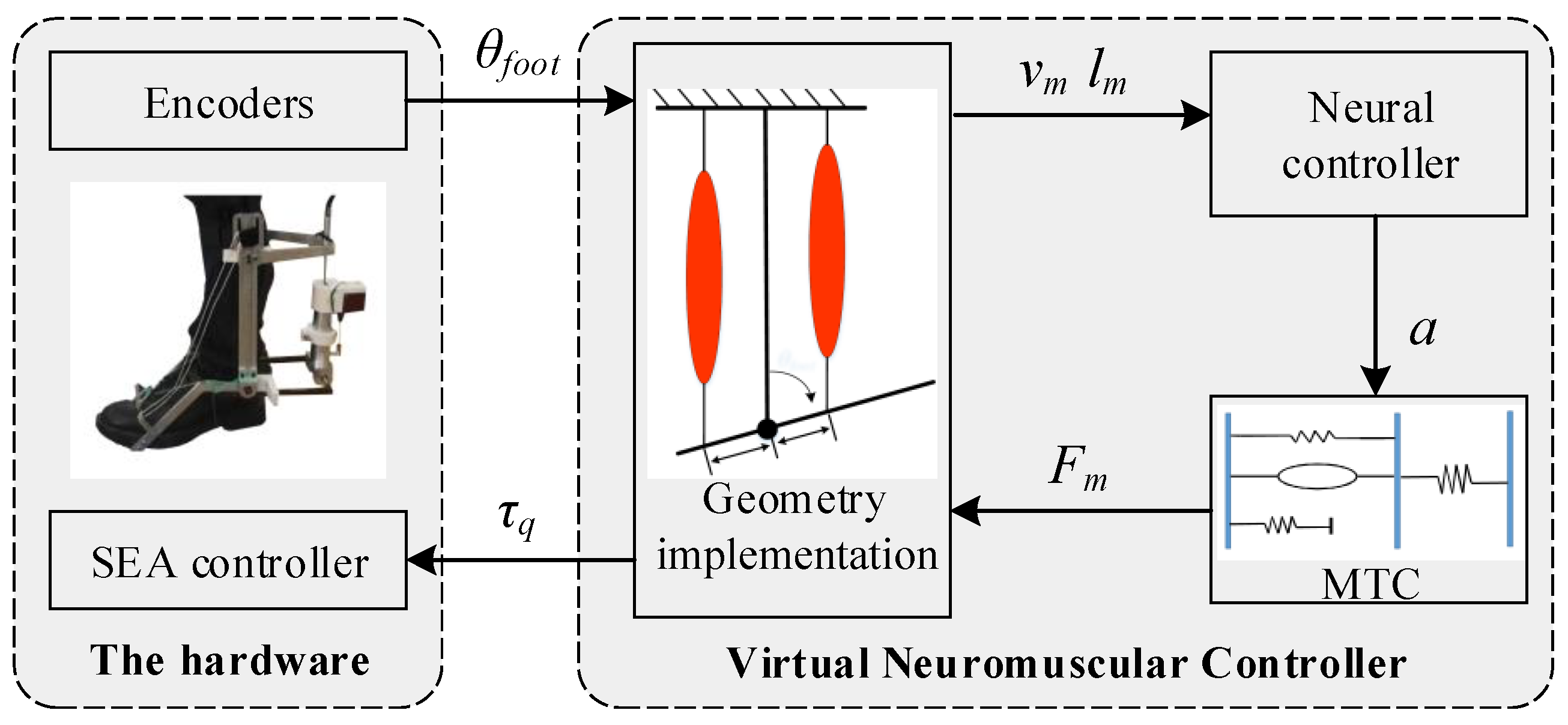
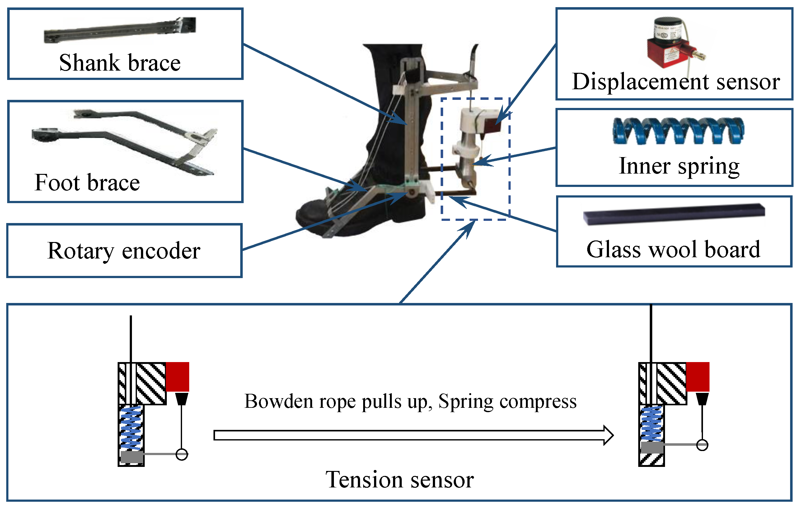
2.1. System Overview

The overall architecture of the proposed virtual neuromuscular control strategy is illustrated in Figure 1. In particular, the ankle exoskeleton is driven by two virtual muscles that simulate the effects of the two groups of muscles in the humanoid ankle [19], including the virtual plantar flexor muscle (PFM) and the virtual dorsiflexor muscle group (DFM).
The data flow in the interconnected closed control loops guarantees the strong robustness of the proposed control approach. The musculoskeletal mechanics include two key components, including virtual muscle mechanical model and geometry implementation. The inputs of the geometry implementation are the ankle angles ( θ f o o t ), which are measured from the hardware and mapped to virtual measurements required, including the virtual muscle spindle length ( l m ), virtual muscle spindle contraction velocity ( v m ) and virtual muscle attachment radius (r). The virtual muscle mechanical model is simplified as a muscle–tendon complex (MTC), and used to generate the corresponding virtual muscle force ( F m ) based on the virtual muscle activation (a) calculated from the neural controller. The virtual muscle force is passed to the geometry implementation to estimate the desired assistance torque ( τ q ), which is then passed to the SEA controller to drive the exoskeleton to perform the desired action.

2.2. Musculoskeletal Mechanics

In this work, the ankle exoskeleton is actuated by two groups of virtual muscles. Both groups of virtual muscles can be simplified as a muscle–tendon complex (MTC) model, named virtual muscle mechanical model in this paper. Under the dominance of the neural controller and virtual muscle state, the virtual muscle mechanical model realizes voluntary contraction and then generates the virtual muscle force.

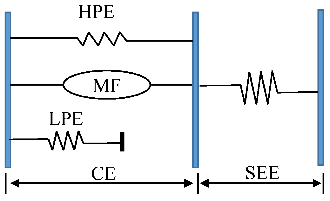
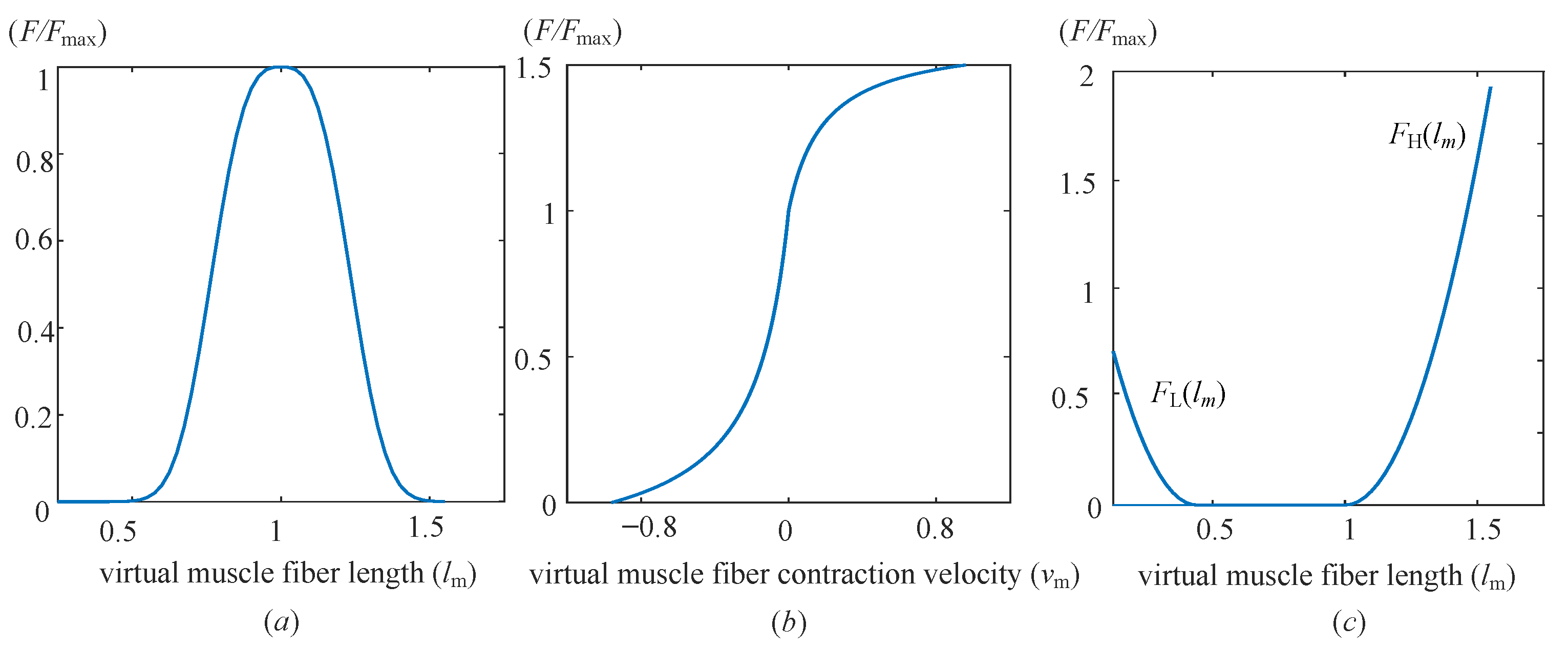
2.2.1. Virtual Muscle Mechanical Model

The virtual muscle mechanical model is combined by a contractile element (CE) and a series elastic element (SEE), as shown in Figure 2, which represents a combination of humanoid ankle plantar flexor muscle and dorsiflexor muscle. The CE consists of three components, including a muscle fiber (MF), a high-limit parallel elastic component (HPE), and a low-limit parallel elastic component (LPE). Whilst the SEE is represented as a non-linear, unidirectional spring.
The active component of the CE is the MF, which generates a unidirectional muscle force. The force of MF ( F M F ) is determined by the virtual muscle fiber length ( l m ), the virtual muscle spindle contraction velocity ( v m ), the virtual muscle activation (a), and the maximum muscle fibers force ( F max ), which can be expressed as:
F M F l m , v m , a = a F max f l l m f v v m
where f l ( l m ) represents the force–length relationship function, and f v ( v m ) stands for the force–velocity relationship function.
The force–length relationship function is a bell-shaped curve and shown in Figure 3a, which can be defined as [20]:
f l l m = exp c l m l o l o ω 3
where l o is the optimum length of the virtual muscle fibers as the virtual muscle provides the maximum fiber force, ω represents the width of the bell-shaped curve, c denotes the curve’s magnitude, which is defined as l n ( 0.05 ) in this work.
The force–velocity relationship function is the Hill equation and can be represented as an “S” shaped curve as illustrated in Figure 3b, which is defined by [21]:
f v v m = v max v m / v max + K v m , v m < 0 N + ( N 1 ) v max + v m 7.56 K v m v max , v m 0
where v m a x describes the maximum contractile velocity of the virtual muscle fibers, K denotes the curvature constant, and N is the dimensionless muscle force that is normalized by F m a x .
The force of HPE ( F H ) is not dominated by CNS, only affected by the stretching of the virtual muscle fibers. The force–length relationship function for HPE is illustrated in the right side of Figure 3c, and can be expressed as:
F H l m = F max l m l o / l o ω 2 , l m > l o 0 , otherwise
Likewise, the force–length relationship function for LPE is also only affected by the contraction of the virtual muscle fibers. The force–length relationship function for LPE is illustrated in the left side of Figure 3c, and then can be given by:
F L l m = F max l m l o ( 1 ω ) / l o 2 ( ω / 2 ) , l M F l o ( 1 ω ) 0 , otherwise
The force of CE ( F C E ) can be expressed by:
F C E = F M F l m · v m , a + F H l m F L l m
Since the CE and SE are series connection, and then the following equation holds:
F C E = F S E = F m
where the F S E represents the force of the SEE and F m denotes the force of the groups of virtual muscles.

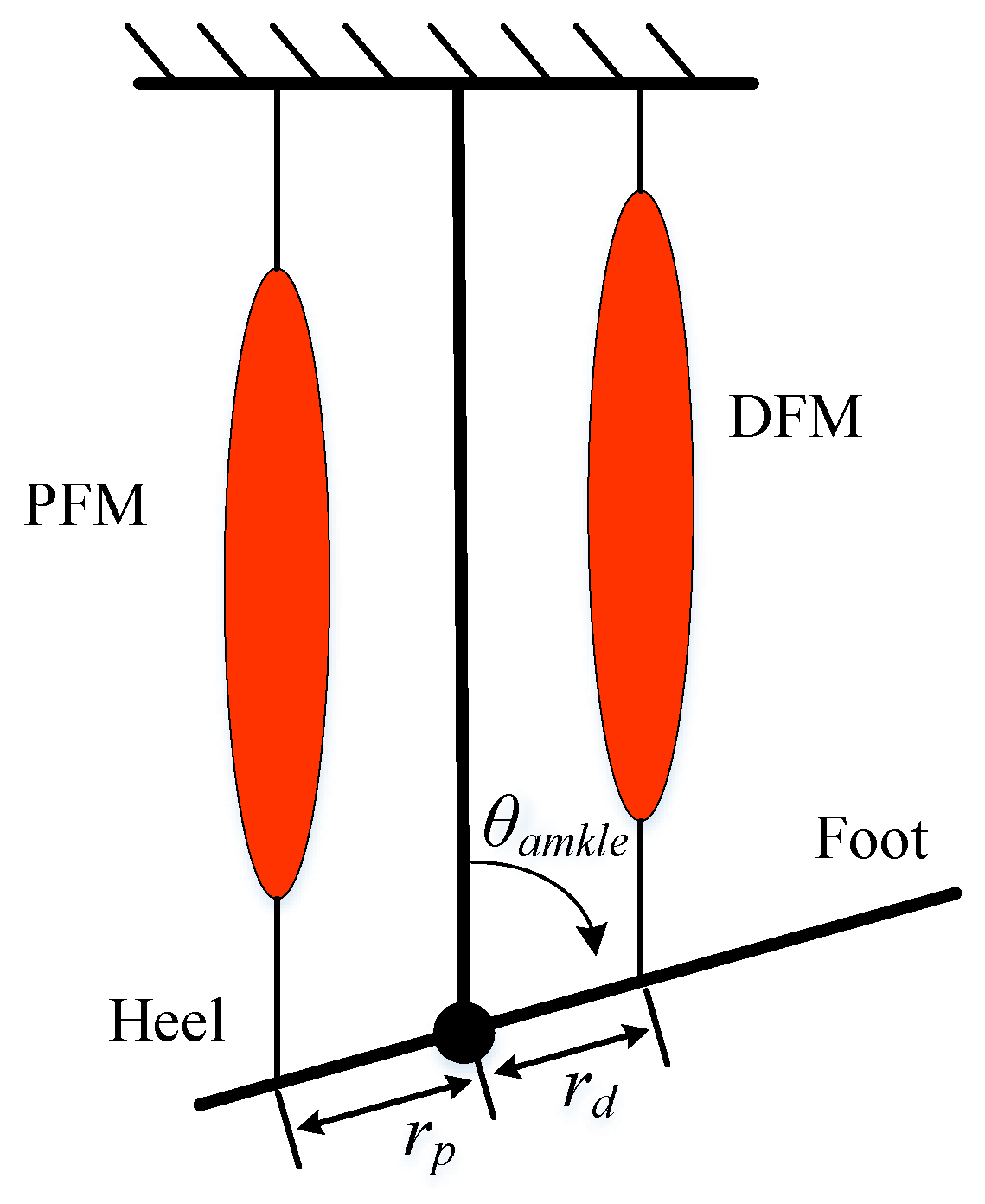
2.2.2. Geometry Implementation

The ankle exoskeleton angle is defined as the angle between the foot and the shank segment as shown in Figure 4. According to this angle, the length of the virtual muscle fiber can be calculated by:
l m = r ρ sin θ f o o t θ m a x sin θ o p t θ m a x + l o p t
where r stands for the attachment radius of the virtual muscle, and ρ describes the scaling factor. l o p t is an optimal virtual muscle spindle length, at which it can provide the maximum muscle force. At the moment, the ankle angle is described by θ o p t , and θ m a x is a constant ankle angle as the maximum virtual muscle moment arm.
For the task of a standing balance control, the variation range of ankle angle is usually small, subject to s i n ( θ o p t θ m a x ) θ o p t θ m a x , so the virtual muscle spindle length can be simply expressed as:
l m = K θ f o o t θ m a x + C
where K = r ρ is a constant gain, and C = K s i n ( θ o p t θ m a x ) + l o p t is another constant gain.
The virtual muscle spindle contraction velocity ( v m ) can be calculated via the time derivative of virtual muscle spindle length, which can be expressed as:
v m = K θ ˙ f o o t
The desired assistance torque is estimated by two groups of virtual muscles, including PFM and DFM, as shown in the above Figure 4. The virtual muscle force ( F m 1 , F m 2 ) can be calculated using Equation (7), and then acts on the ankle exoskeleton through the moment arm of the two virtual muscles ( r p , r d ). The moment arms are determined by the ankle angle and can be expressed by:
r = r max cos θ f o o t θ max
where r max is the maximum joint moment arm, which occurs at the ankle angle max.
Form this, the desired assistance torque ( τ q ) produced by the two groups of virtual muscle can be calculated by:
τ q = F m 1 r p + F m 2 r d

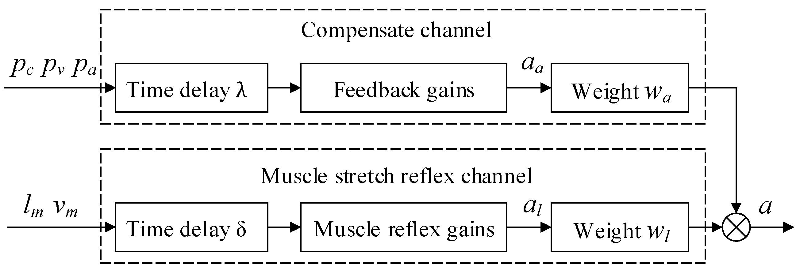
2.3. Neural Controller

The neural controller is used to imitate the human natural central nervous system (CNS) control mechanism. The function of the neural control is according to the virtual muscle spindle length information and the position information of the center of mass (CoM) of the wearer to obtain the virtual muscle activation ( a 1 , a 2 ).
The human natural CNS includes two prime structures: spinal cord and the brain, which can be regarded as a hierarchical control structure [22]. The brain is usually referred to as an advanced central nervous system (ACNS), and the spinal cord is often known as the lower central nervous system (LCNS). Based on neurological research [23], the ACNS and LCNS work together to maintain human upright balance. The sense organs of ACNS involve the proprioceptive system, vestibular system, and visual system [24]. The LCNS is implemented through the muscle stretch reflex in human upright balance control, and the senses organs are combined by the Golgi tendon organ, and spindle organs.
In order to apply the human natural CNS control mechanism to the ankle exoskeleton control, the CNS control circuit needs to be simplified to avoid the intervention of complex signals. The neural controller is proposed to imitate the human natural CNS and directly obtain virtual muscle activation through the ankle exoskeleton motion signal. The proposed neural controller is illustrated in Figure 5, which has two control channels in parallel, with the muscle stretch reflex channel to imitate LCNS and the compensate channel to imitate ACNS. The two control channels guarantee strong complementarity in producing fast and accurate actions. The input of the muscle stretch reflex channel is the virtual muscle spindle length information ( l m , v m ), subject to a time delay ( δ ) to simulate the neural transmission and processing time, and it calculates the muscle activation ( a l ) produced by muscle stretch reflex channel. The input of the compensate channel is the position of the wearer’s CoM ( p c , p v , p a ), subject to a time delay ( λ ), and the output is the muscle activation ( a a ) produced by the compensate channel. From this, the final estimated muscle activation is aggregated the output of a l and a a .
The muscle stretch reflex is a fast muscle contraction generation mechanism. In this work, the sensory information of the muscle stretch reflex channel is the virtual muscle spindle length change and its contraction velocity. The virtual muscle activation produced by the muscle stretch reflex can be generated using a positive feedback reflex scheme with signal propagation time delay ( δ ), which can be computed as:
a l ( t ) = p l l m ( t δ ) + d v v m ( t δ )
where p l and d v are the gains for virtual muscle spindle length and its contraction velocity.
Based on the concept of nonlinear parameters in control theory, this paper proposed nonlinear signal gain in the virtual muscle stretch reflex channel. The concept can be described as the signal gain increases with the increasing of the virtual muscle spindle length or the muscle spindle contraction velocity, and vice versa. The nonlinear signal gains can be defined as:
p l ( t ) = p l 0 + K p l m l m 0 d v ( t ) = d v 0 + K d v m
where p l 0 and d v 0 stand for the constant initial gains, and K p and K d represent the constant coefficients, respectively.
According to Equations (9) and (10), the Equation (13) can be re-expressed as:
a l = G l Δ θ ( t δ ) + G v θ ( t δ ) θ ˙ 0
where G l = p l K , G v = d v K , Δ ( t δ ) = θ f o o t ( t δ ) θ 0 , and θ 0 is the ankle angle in ankle exoskeleton standing equilibrium state.
The compensate channel is used to reinforce the activation of the virtual muscle to complement the muscle stretch reflex channel, with overlapping contributions of wearer’s CoM trajectories horizontal displacement ( p c ), velocity ( p v ), acceleration ( a c ), and a signal-propagation time delay ( λ ). The muscle activation produced by compensating channel can be calculated by:
a a ( t ) = k p p c ( t λ ) + k v p v ( t λ ) + k a p a ( t λ )
where k p , k v and k a stand for the compensate channel gain coefficients.
The virtual muscle activation results from the two channels should be aggregated to produce the total virtual muscle activation. Information aggregation has been well studied, such as, fuzzy inference [25], neural network, and Bayes estimation [26], among others [27]. In order to avoid involve complex operations, this work takes the simplest variable weight summation method as the aggregation approach, which can be expressed as:
a ( t ) = a 0 + a l ( t ) t < δ a 0 + w l a l ( t ) + w c a a ( t ) t δ
where a 0 is the pre-activation value, and w l and w c are the weights of the two channels, respectively. The current virtual muscle activation, at any time before δ , is equal to the pre-activation plus the activation of the muscle stretch reflex channel; at any time after δ , the current virtual muscle activation is the combination of the pre-activation and the two channels activation results.
The weights are linearly correlated with the input information of the two channels, and any reduction of the contribution from one channel will be accompanied by a corresponding increase in the contribution from the other channel. The input normalization information of the two channels are expressed as:
L = l m max l m V = V c max V c
The weights of the two channels are defined as:
w l = L V + L w c = V V + L

3. Experimentation

The proposed virtual neuromuscular control method was applied to an ankle exoskeleton, and several experiments have been carried out in the lab to test the performance of the control method.

3.1. Experiment Condition

A simple version of the ankle exoskeleton was designed and used in this experiment. The mechanical structure mainly includes the foot brace, shank brace, rotary encoder, glass wool board and tension senor, as illustrated in Figure 6. The tension senor was specially designed, which is composed of a displacement sensor and an inner spring. When the bowed rope is pulled up, the inner spring will be compressed. According to Hooke’s law, the tension of the bowed rope can be calculated:
F e x = K x × x s
where K x represents the spring stiffness which is 10.49 N/mm in this paper, x s is the inner spring compression distance measured with the displacement sensor. The performance parameters of the rotary encoder and displacement sensor are shown in Table 1.
To guarantee wearable suitability, the ankle exoskeleton is designed at a similar size to the human lower limb. The Boden rope is used as the transmission device to separate the DC motor from the exoskeleton, in order to light the device. The rope tension is measured by a tension sensor, and the rotation angle is measured by a rotary encoder.
Five healthy neurologically intact participants (male and female, age 21∼35 years) with no history of neurologic disorders gave written informed consent and participated in the study. The participants wear an ankle exoskeleton and stand on the moving vehicle. The vehicle acceleration and deceleration as the perturbation for the upright balance, and the vehicle moving process during one experiment is shown in Figure 7. During the experiment, the surface electromyography (sEmg) from the participants’ Gastrocnemius (Gas) and Soleus (Sol) were recorded using a sEmg acquisition instrument. In order to verify the effectiveness of the proposed virtual neuromuscular control method, three sets of comparative experiments were carried out. In the both three sets of experiment, four different acceleration were applied to the vehicle: 0.6 m/s 2 , 0.8 m/s 2 , 1.0 m/s 2 and 1.2 m/s 2 . Each experiment was repeated five times. The specific experimental scheme are summarized below:
Case A: The exoskeleton is not actuated. In order to test the effects of the ankle exoskeleton on participants’ lower limb muscle activation during the upright balance, the participants wear the un-actuated ankle exoskeleton.
Case B: The exoskeleton is controlled by the virtual-ankle stiffness control method. Virtual-ankle stiffness control is the representative control method for ankle exoskeleton upright balance control, the desired assistance torque ( τ v ) can be expressed as:
τ v = K a ( θ f o o t θ r e f )
where θ f o o t is the actual ankle angle, θ r e f stands for the ankle reference angle at the equilibrium position. The parameter K a can be calculated as:
K a = τ max τ min θ max θ min × 1 3
where τ max and τ min indicate the maximum and minimum assistance torque, θ max and θ min stand for the maximum and minimum ankle angle, respectively.
Case C: The exoskeleton is controlled by the proposed virtual neuromuscular control method. With reference to the important conclusion of biomedical research on the human ankle calf muscle [22], which provides the guidance for controller parameters setting, the virtual muscle mechanical model parameters in the experiment are shown in Table 2, and the parameters of the neural control are shown in Table 3.

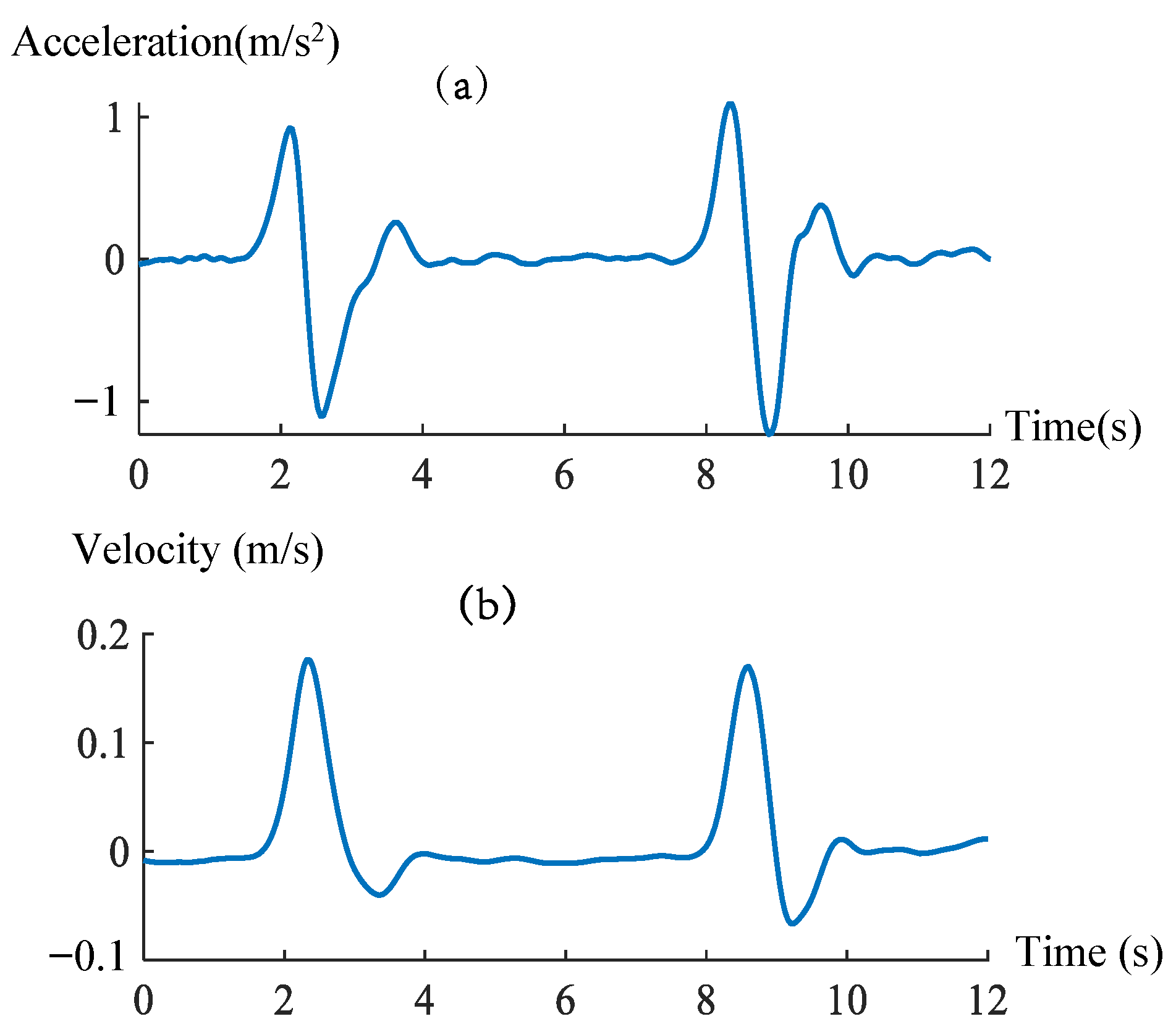
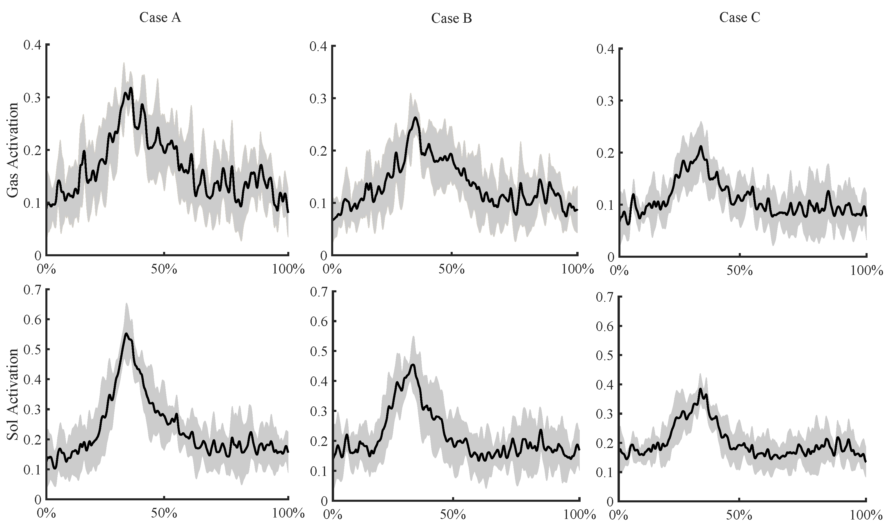
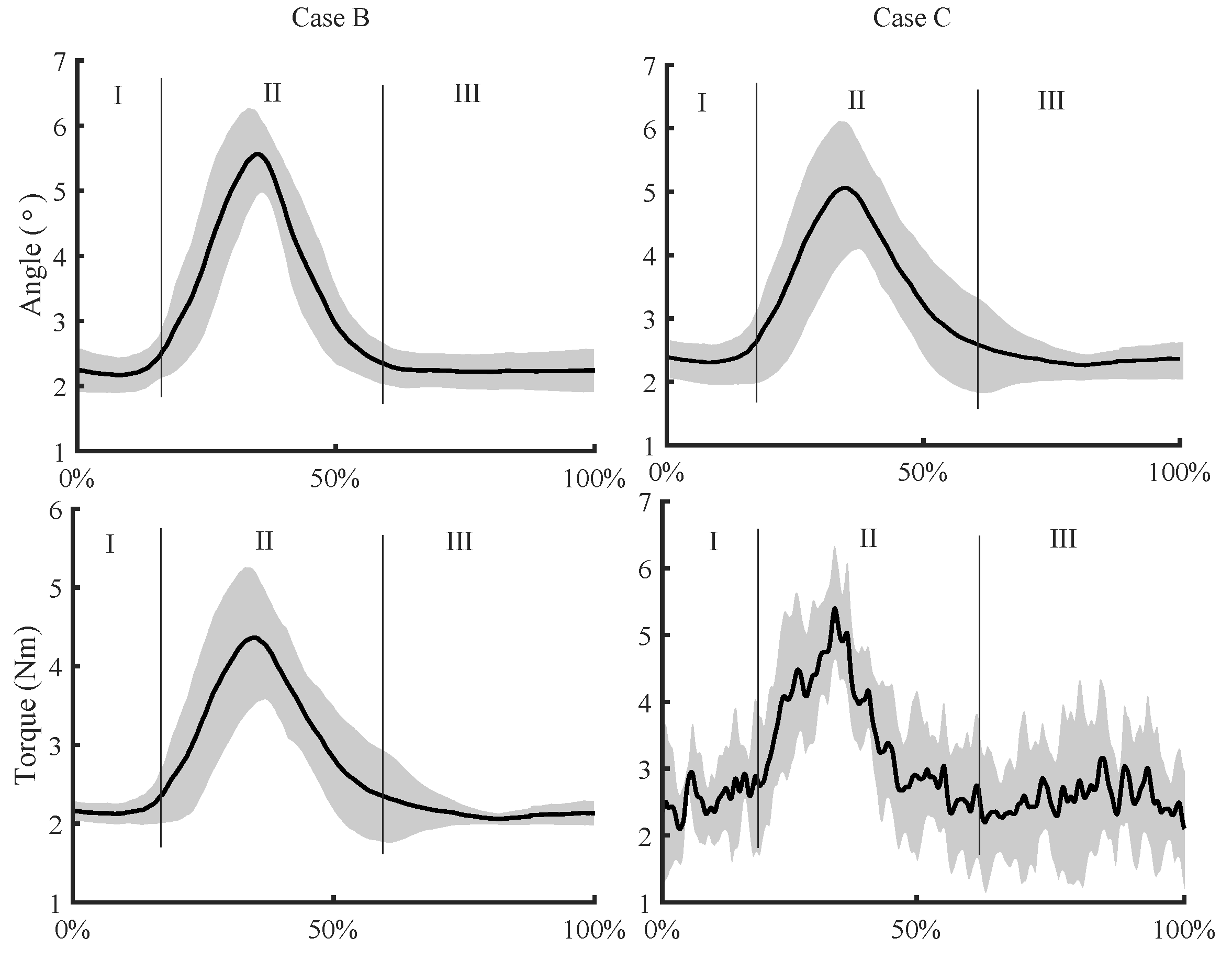
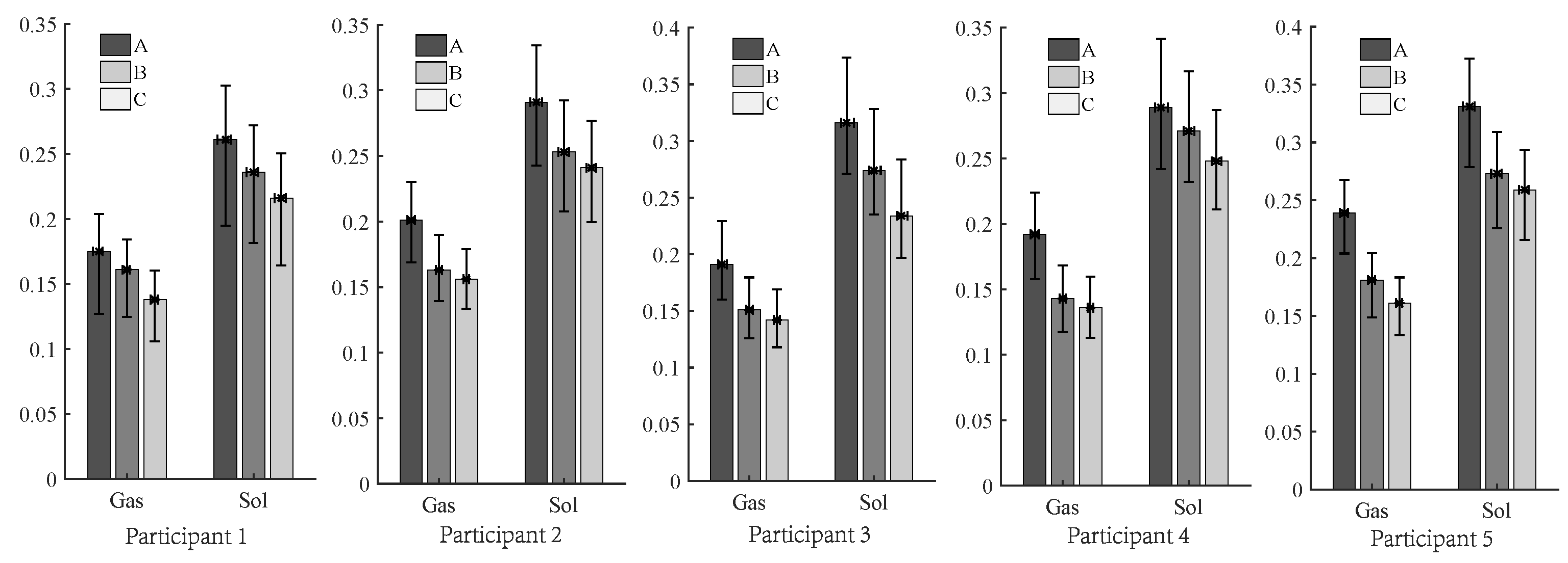
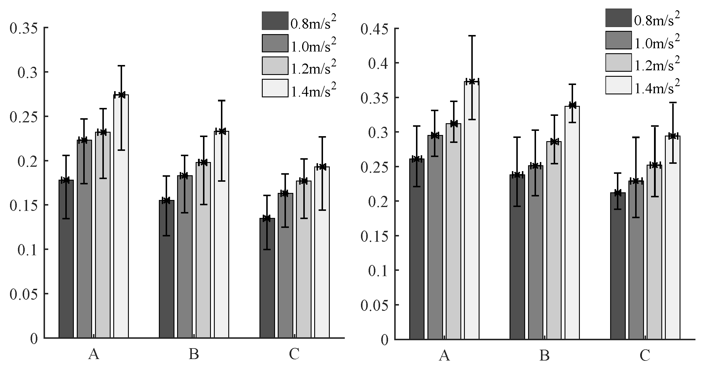
3.2. Experimentation Results

In the experimentation, the movement of the vehicle breaks the equilibrium state of the participant. Taking participant 1 and the vehicle acceleration of 0.8 m/s 2 as an example, the activation of Gas muscle and Sol muscle in three case experiments is illustrated in Figure 8. In this figure, the solid black represents the averaged time courses of muscle activation measurement results, the grey-shaded regions indicate SD from the mean measurement results across all five trials in each case experimentation.
In the process of human upright balance control, the activation of Gas muscle and Sol muscle has obvious fluctuation and a peak. It means that the Gas muscle and Sol muscle play an important role in the process of human balance control. From this figure, it can be seen that the peaks of Gas muscle and Sol muscle activation were reduced under Case B and C experimentation, particularly Case C experimentation. It indicates that the exoskeleton provides an assist for the balance control in Case B and C experimentation.
In order to better analyze the performance of the two controllers in Case B and C experimentation, the ankle angle of participants and the output torque of the controller are recorded and shown in Figure 9. In this figure, the solid black represents the averaged time courses of recorded results. The grey-shaded regions indicate SD from the mean measurement results across all five trials in each case experimentation. For the ankle angle, the counterclockwise swing is defined as the negative direction, on the contrary, the clockwise swing is defined as the positive direction. According to the amplitude of ankle angle, the experimentation process can be divided into three stages.
(1) In stage I, the vehicle is stationary, which means there is no external disturbance, the participant can quickly adjust to the equilibrium state, and the ankle torque does not change much.
(2) In stage II, the vehicle applies an instantaneous positive acceleration and then an instantaneous negative acceleration, and the vehicle eventually becomes stationary. In this process, the Case B and C experimentation have the same performance. The participant’s body tilt leans forward first, and then leans backward. The ankle angle gradually stabilized at around 2.2°. It is important to point out that the peak angles of Case B and C experimentation are 5.6° and 5.0°, respectively. This means that the proposed control method showed a better control performance than the virtual-ankle stiffness control method.
(3) In stage III, the vehicle is stationary, which is similar to state I. The participant quickly adjusts to the equilibrium position.
For a better illustration, the root-mean-squared (RMS) of muscle activation was calculated to assess the assisted fitness. The muscle activation RMS values of participants in the three experiments are shown in Figure 10, with error bars representing standard deviation. The maximum standard deviation was 0.05, which has less effect on this experiment. According to Case A and Case B experimentation results, the RMS of Gas muscle and Sol muscle in Case B experimentation were reduced by an average of 20.33 % , and 17.29 % , respectively. The results indicated that the ankle exoskeleton can effectively assist the participant to resist disturbance upright under the virtual-ankle stiffness control method. By comparing Case B and Case C experimentation results, the RMS of Gas muscle and Sol muscle in Case C experimentation were reduced by an average of 3.12 % , and 4.78 % , respectively. The results showed that the proposed virtual neuromuscular control method improves the performance of the ankle exoskeleton in the process of assisting the participant to resist disturbance upright.
To facilitate the evaluation of the robustness of the proposed virtual neuromuscular control method for different external disturbances, four different acceleration were applied to the vehicle: 0.6 m/s 2 , 0.8 m/s 2 , 1.0 m/s 2 and 1.2 m/s 2 . The muscle activation RMS value of participant one under different vehicle moving acceleration as shown in Figure 11, with error bars representing standard deviation. The maximum standard deviation was 0.055, which has less effect on this experiment. From this figure, it is clear that for different external disturbances, the muscle activation RMS values were different, and the larger the vehicle acceleration, the the larger the muscle activation RMS. In comparison, both Gas and Sol muscle activation RMS vale are small under Case C experimentation. This indicates that the proposed virtual neuromuscular control method improves the robustness of the ankle exoskeleton for different external disturbances. This is reasonable, as the virtual neuromuscular control simulates the muscle function in human activity, and the muscle has the ability to adapt adjustments for the various working states of the human, which therefore effectively implemented the robustness support of ankle exoskeleton standing balance control.

4. Conclusions

Standing balance control plays a key role in promoting the dynamic balancing performance of the ankle exoskeleton. Focusing on improving the control robustness, this paper presents a virtual neuromuscular control for robotic ankle exoskeleton standing balance, which was used to calculate the desired ankle torque. In particular, the neuromuscular model consists of two components, the proposed control method has two key components, including musculoskeletal mechanics and neural control. The results based on three sets of comparative experiments demonstrated the efficacy and robustness of the proposed control method for robotic ankle exoskeleton standing balance. Although the proposed control method targets the ankle exoskeleton, it is readily applicable to the other robotic exoskeleton, which remains a piece of future work.

Author Contributions

K.Y. contributed to the conception of the study, the background research, method design and analysis of the experimental results; Y.J. performed methodological guidance and writing review; H.D. wrote the manuscript; Y.X. provided methodological guidance, writing review and funding support; P.L. reviewed and revised the manuscript; Z.M. carried out the experiment. All authors have read and agreed to the published version of the manuscript.

Funding

This research is funded by the Project of the Science and Technology Department of Henan Province under Grant 222102220116, Grant 212102210017, and Grant 202102310197, and by the High-level talent start-up fund of Pingdingshan University under Grant PXY-BSQD-2021019.

Institutional Review Board Statement

Not applicable.

Informed Consent Statement

Informed consent was obtained from all subjects involved in the study.

Data Availability Statement

Not applicable.

Conflicts of Interest

The authors declare no conflict of interest.

References

  1. Hussain, S.; Jamwal, P.K.; Vliet, P.V.; Brown, N.A. Robot assisted ankle neuro-rehabilitation: State of the art and future challenges. Expert Rev. Neurother. 2021, 21, 111–121. [Google Scholar] [CrossRef]
  2. Baud, R.; Manzoori, A.R.; Ijspeert, A.; Bouri, M. Review of control strategies for lower-limb exoskeletons to assist gait. J. Neuroeng. Rehabil. 2021, 18, 119. [Google Scholar] [CrossRef] [PubMed]
  3. Kapsalyamov, A.; Jamwal, P.K.; Hussain, S.; Ghayesh, M.H. State of the art lower limb robotic exoskeletons for elderly assistance. IEEE Access 2019, 7, 95075–95086. [Google Scholar] [CrossRef]
  4. Ishmael, M.K.; Archangeli, D.; Lenzi, T. Powered hip exoskeleton improves walking economy in individuals with above-knee amputation. Nat. Med. 2021, 27, 1783–1788. [Google Scholar] [CrossRef] [PubMed]
  5. Esquenazi, A.; Talaty, M.; Jayaraman, A. Powered exoskeletons for walking assistance in persons with central nervous system injuries: A narrative review. PM&R 2017, 9, 46–62. [Google Scholar]
  6. Gatev, P.; Thomas, S.; Kepple, T.; Hallett, M. Feedforward ankle strategy of balance during quiet stance in adults. J. Physiol. 1999, 514, 915–928. [Google Scholar] [CrossRef]
  7. Han, B.I.; Song, H.S.; Kim, J.S. Vestibular rehabilitation therapy: Review of indications, mechanisms, and key exercises. J. Clin. Neurol. 2011, 7, 184–196. [Google Scholar] [CrossRef] [PubMed] [Green Version]
  8. Bayón, C.; Keemink, A.Q.; van Mierlo, M.; Rampeltshammer, W.; van der Kooij, H.; van Asseldonk, E.H. Cooperative ankle-exoskeleton control can reduce effort to recover balance after unexpected disturbances during walking. J. Neuroeng. Rehabil. 2022, 19, 21. [Google Scholar] [CrossRef]
  9. Bishe, S.S.P.A.; Nguyen, T.; Fang, Y.; Lerner, Z.F. Adaptive ankle exoskeleton control: Validation across diverse walking conditions. IEEE Trans. Med. Robot. Bionics 2021, 3, 801–812. [Google Scholar] [CrossRef]
  10. Zhang, J.; Fiers, P.; Witte, K.A.; Jackson, R.W.; Poggensee, K.L.; Atkeson, C.G.; Collins, S.H. Human-in-the-loop optimization of exoskeleton assistance during walking. Science 2017, 356, 1280–1284. [Google Scholar] [CrossRef] [Green Version]
  11. Zhang, J.; Collins, S.H. The iterative learning gain that optimizes real-time torque tracking for ankle exoskeletons in human walking under gait variations. Front. Neurorobot. 2021, 15, 65. [Google Scholar] [CrossRef] [PubMed]
  12. Jackson, R.W.; Collins, S.H. Heuristic-based ankle exoskeleton control for co-adaptive assistance of human locomotion. IEEE Trans. Neural Syst. Rehabil. Eng. 2019, 27, 2059–2069. [Google Scholar] [CrossRef] [PubMed]
  13. Zhang, J.; Cheah, C.C.; Collins, S.H. Experimental comparison of torque control methods on an ankle exoskeleton during human walking. In Proceedings of the 2015 IEEE International Conference on Robotics and Automation (ICRA), Seattle, WA, USA, 26–30 May 2015; pp. 5584–5589. [Google Scholar]
  14. Tang, Z.; Yu, H.; Yang, H.; Zhang, L.; Zhang, L. Effect of velocity and acceleration in joint angle estimation for an emg-based upper-limb exoskeleton control. Comput. Biol. Med. 2022, 141, 105156. [Google Scholar] [CrossRef] [PubMed]
  15. Yang, G.-Z.; Bellingham, J.; Dupont, P.E.; Fischer, P.; Floridi, L.; Full, R.; Jacobstein, N.; Kumar, V.; McNutt, M.; Merrifield, R.; et al. The grand challenges of science robotics. Sci. Robot. 2018, 3, eaar7650. [Google Scholar] [CrossRef]
  16. Thatte, N.; Geyer, H. Toward balance recovery with leg prostheses using neuromuscular model control. IEEE Trans. Biomed. Eng. 2015, 63, 904–913. [Google Scholar] [CrossRef]
  17. Desai, R.; Geyer, H. Muscle-reflex control of robust swing leg placement. In Proceedings of the 2013 IEEE International Conference on Robotics and Automation, Karlsruhe, Germany, 6–10 May 2013; pp. 2169–2174. [Google Scholar]
  18. Pang, M.; Xu, X.; Tang, B.; Xiang, K.; Ju, Z. Evaluation of calf muscle reflex control in the ‘ankle strategy’ during upright standing push-recovery. Appl. Sci. 2019, 9, 2085. [Google Scholar] [CrossRef] [Green Version]
  19. Yin, K.; Xiang, K.; Pang, M.; Chen, J.; Anderson, P.; Yang, L. Personalised control of robotic ankle exoskeleton through experience-based adaptive fuzzy inference. IEEE Access 2019, 7, 72221–72233. [Google Scholar] [CrossRef]
  20. Geyer, H.; Seyfarth, A.; Blickhan, R. Positive force feedback in bouncing gaits? Proc. R. Soc. Lond. B Biol. Sci. 2003, 270, 2173–2183. [Google Scholar] [CrossRef]
  21. Hill, A.V. The heat of shortening and the dynamic constants of muscle. Proc. R. Soc. Lond. B Biol. Sci. 1938, 126, 136–195. [Google Scholar]
  22. Yin, K.; Chen, J.; Xiang, K.; Pang, M.; Tang, B.; Li, J.; Yang, L. Artificial human balance control by calf muscle activation modelling. IEEE Access 2020, 8, 86732–86744. [Google Scholar] [CrossRef]
  23. Takakusaki, K.; Takahashi, M.; Obara, K.; Chiba, R. Neural substrates involved in the control of posture. Adv. Robot. 2017, 31, 2–23. [Google Scholar] [CrossRef]
  24. Nishikawa, K.; Biewener, A.A.; Aerts, P.; Ahn, A.N.; Chiel, H.J.; Daley, M.A.; Daniel, T.L.; Full, R.J.; Hale, M.E.; Hedrick, T.L.; et al. Neuromechanics: An integrative approach for understanding motor control. Integr. Comp. Biol. 2007, 47, 16–54. [Google Scholar] [CrossRef] [PubMed] [Green Version]
  25. Wei, G.; Wang, H.; Zhao, X.; Lin, R. Hesitant triangular fuzzy information aggregation in multiple attribute decision making. J. Intell. Fuzzy Syst. 2014, 26, 1201–1209. [Google Scholar] [CrossRef]
  26. Venanzi, M.; Guiver, J.; Kohli, P.; Jennings, N.R. Time-sensitive bayesian information aggregation for crowdsourcing systems. J. Artif. Intell. Res. 2016, 56, 517–545. [Google Scholar] [CrossRef] [Green Version]
  27. Xu, Z.; Da, Q.-L. An overview of operators for aggregating information. Int. J. Intell. Syst. 2003, 18, 953–969. [Google Scholar] [CrossRef]
Figure 1. The overall architecture of the proposed bipedal robots upright balance control strategy.
Machines 10 00572 g001
Figure 2. The virtual muscle mechanical model.
Machines 10 00572 g002
Figure 3. Contractiondynamics of the CE. (a) Force–length relationship (Equation (2)). (b) Force–velocity relationship (Equation (3)). (c) Parallel elastic component force (Equations (4) and (5)).
Machines 10 00572 g003
Figure 4. The geometry of ankle exoskeleton with two groups of virtual muscles.
Machines 10 00572 g004
Figure 5. The framework of virtual muscle activation model.
Machines 10 00572 g005
Figure 6. Schematic diagram of exoskeleton wearing part.
Machines 10 00572 g006
Figure 7. The vehicle moving process. (a) Vehicle acceleration. (b) Vehicle velocity.
Machines 10 00572 g007
Figure 8. Muscle activation measurement results of participants in three case of experimentation.
Machines 10 00572 g008
Figure 9. Ankle angle measurement results of participants and the output torque of the controller.
Machines 10 00572 g009
Figure 10. The muscle activation RMS value of participants under 0.8 m/s 2 vehicle acceleration.
Machines 10 00572 g010
Figure 11. The muscle activation RMS value of participant one under different vehicle moving acceleration.
Machines 10 00572 g011
Table 1. The performance parameters of the rotary encoder and displacement sensor.
SensorAccuracyResolutionMeasurement Range
Rotary encoder 0.1 360 / 4096 0∼360
Displacement sensor ± 0.1 % FS 0.1 mm50∼150 mm
Table 2. The parameters of virtual muscle mechanical model.
ParametersPFMDFM
F m a x (kg)600800
v m a x (cm/s)3648
l o p t (cm)64
r m a x 45
θ m a x (deg)80110
θ o p t (deg)11080
ρ 0.50.7
Table 3. The parameters of neural controller.
ParametersPFMDFM
p l 0 0.10.1
d v 0 0.050.05
G l 3.14.2
G v 0.110.16
k p 0.150.12
k v 0.080.06
k a 0.030.04
Publisher’s Note: MDPI stays neutral with regard to jurisdictional claims in published maps and institutional affiliations.

